US7806462B2 - Device for guiding a drop window - Google Patents
Device for guiding a drop window Download PDFInfo
- Publication number
- US7806462B2 US7806462B2 US12/260,905 US26090508A US7806462B2 US 7806462 B2 US7806462 B2 US 7806462B2 US 26090508 A US26090508 A US 26090508A US 7806462 B2 US7806462 B2 US 7806462B2
- Authority
- US
- United States
- Prior art keywords
- deflector
- guide rail
- rail
- vehicle door
- drop window
- Prior art date
- Legal status (The legal status is an assumption and is not a legal conclusion. Google has not performed a legal analysis and makes no representation as to the accuracy of the status listed.)
- Expired - Fee Related
Links
- 238000007789 sealing Methods 0.000 claims description 4
- 229910000639 Spring steel Inorganic materials 0.000 claims description 3
- 238000009434 installation Methods 0.000 description 2
Images

Classifications
-
- B—PERFORMING OPERATIONS; TRANSPORTING
- B60—VEHICLES IN GENERAL
- B60J—WINDOWS, WINDSCREENS, NON-FIXED ROOFS, DOORS, OR SIMILAR DEVICES FOR VEHICLES; REMOVABLE EXTERNAL PROTECTIVE COVERINGS SPECIALLY ADAPTED FOR VEHICLES
- B60J5/00—Doors
- B60J5/04—Doors arranged at the vehicle sides
- B60J5/0401—Upper door structure
- B60J5/0404—Outside rear view mirror support
Definitions
- the technical field pertains to a device for guiding a drop window in a vehicle door of a motor vehicle that includes, but is not limited to a horizontal shaft rail that adjoins the drop window and a guide rail that is inclined relative to the vertical line, as well as a horizontal flange of the vehicle door in order to mount the shaft rail.
- this at least one objective, other objectives, desirable features, and characteristics are attained in that a deflector extends from the guide rail up to a flange of the vehicle door and features a vertical edge that is guided up to the shaft rail.
- the deflector consequently compensates the incline of the guide rail relative to the vertical line and therefore also prevents a gap from forming between the guide rail and the shaft rail if the guide rail is significantly inclined relative to the vertical line.
- the deflector can thusly prevent the admission of noises or dirt into the interior of the motor vehicle.
- the shaft rail is individually fixed on a clamp that is mounted on the flange of the vehicle door.
- This clamp also serves for mounting an inside lining of the motor vehicle that faces the interior of the motor vehicle.
- the device in accordance with embodiments of the invention is composed of only a few components that can be installed very easily if the shaft rail is fixed on an inside lining of the motor vehicle. This makes it possible to easily combine the shaft rail and the inside lining into a pre-assembled unit. This pre-assembled unit can subsequently be fixed on the flange of the vehicle door, preferably by being attached vertically.
- the deflector provides sufficient protection from dirt and noises if it has an essentially triangular shape.
- the deflector can be installed in a particularly simple fashion if it is fixed in the guide rail.
- the deflector can also be installed in a particularly simple fashion if it features elements for producing a snap-on connection in the guide rail.
- the integral design of the deflector and the locking hook can be achieved in a particularly simple fashion in accordance with another advantageous additional embodiment of the invention, in which the deflector is realized in the form of a sheet of spring steel.
- connection between the deflector and the guide rail is particularly stable if the deflector is screwed or riveted to the guide rail at a distant location referred to the snap-on connection.
- the device in accordance with an embodiment of the invention has a particularly simple constructive design if the guide rail and/or the shaft rail is/are realized integrally with a sealing lip that adjoins the drop window.
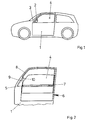
- FIG. 1 shows an inventive motor vehicle with a vehicle door
- FIG. 2 shows an enlarged representation of the vehicle door according to FIG. 1 with a drop window and a deflector
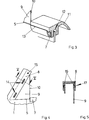
- FIG. 3 shows an enlarged representation of part of the vehicle door with a shaft rail and adjoining regions of the deflector
- FIG. 4 shows an enlarged representation of part of the vehicle door with a guide rail and adjoining regions of the deflector
- FIG. 5 shows a sectional representation of the guide rail and the deflector according to FIG. 4 along the line V-V.
- FIG. 1 shows a motor vehicle with a vehicle door 1 , an exterior rearview mirror 2 and a front windshield 3 that points in the driving direction of the motor vehicle.
- a drop window 4 can be lowered into the vehicle door 1 .
- the vehicle door 1 shown is the driver's door.
- FIG. 2 shows an enlarged representation of part of the vehicle door 1 with the drop window 4 according to FIG. 1 .
- a skin of the vehicle body and the exterior rearview mirror 2 of the vehicle door 1 are not shown. Consequently, a shaft 6 is visible that serves for accommodating the drop window 4 in the lowered state, and the upper boundary of the shaft is formed by a flange 5 of the vehicle door 1 .
- a shaft rail 7 is fixed on the flange 5 of the vehicle door 1 .
- the vehicle door 1 features a guide rail 8 for guiding the drop window 4 .
- the guide rail 8 is inclined relative to the vertical line and carries a deflector 9 .
- the deflector 9 features a vertical edge 10 that extends up to the flange 5 of the vehicle door 1 on its side that faces away from the guide rail 8 .
- the deflector 9 extends up to the shaft rail 7 and therefore spans the distance between the guide rail 8 and the shaft rail 7 .
- the deflector 9 is arranged underneath or behind the exterior rearview mirror 2 illustrated in FIG. 1 .
- FIG. 3 shows an enlarged perspective representation of the connection of the shaft rail 7 on the deflector 9 .
- the shaft rail 7 is fixed on an inside lining 11 of the vehicle door 1 of the motor vehicle.
- the inside lining 11 features a groove 12 for being attached to the flange 5 of the vehicle door 1 and forms a pre-assembled structural unit together with the shaft rail 7 .
- the installation of the inside lining 11 on the flange 5 takes place in the vertical direction along the edge 10 of the deflector 9 .
- the deflector 9 directly adjoins the shaft rail 7 .
- FIG. 3 also shows that the shaft rail 7 is realized integrally with a sealing lip 13 that adjoins the drop window 4 .
- FIG. 4 shows part of the vehicle door 1 with the guide rail 8 and the deflector 9 .
- the deflector 9 features elements for producing snap-on connections 14 in the guide rail 8 , as well as a riveted connection 15 at a distant location referred to the snap-on connections 14 .
- FIG. 5 shows a section along the line V-V in FIG. 4 , in which the snap-on connections 14 feature locking hooks 16 that are realized integrally with the deflector 9 .
- the locking hooks 16 penetrate into recesses 17 of the guide rail 8 in order to mount the deflector 9 .
- the deflector 9 is manufactured of spring steel for this purpose.
Landscapes
- Engineering & Computer Science (AREA)
- Mechanical Engineering (AREA)
- Window Of Vehicle (AREA)
- Power-Operated Mechanisms For Wings (AREA)
Abstract
Description
Claims (8)
Applications Claiming Priority (3)
| Application Number | Priority Date | Filing Date | Title |
|---|---|---|---|
| DE102007052618A DE102007052618A1 (en) | 2007-11-05 | 2007-11-05 | Device for guiding a fall washer |
| DE102007052618 | 2007-11-05 | ||
| DE102007052618.2 | 2007-11-05 |
Publications (2)
| Publication Number | Publication Date |
|---|---|
| US20090113807A1 US20090113807A1 (en) | 2009-05-07 |
| US7806462B2 true US7806462B2 (en) | 2010-10-05 |
Family
ID=40514363
Family Applications (1)
| Application Number | Title | Priority Date | Filing Date |
|---|---|---|---|
| US12/260,905 Expired - Fee Related US7806462B2 (en) | 2007-11-05 | 2008-10-29 | Device for guiding a drop window |
Country Status (4)
| Country | Link |
|---|---|
| US (1) | US7806462B2 (en) |
| CN (1) | CN101429839B (en) |
| DE (1) | DE102007052618A1 (en) |
| RU (1) | RU2469873C2 (en) |
Cited By (4)
| Publication number | Priority date | Publication date | Assignee | Title |
|---|---|---|---|---|
| US9010841B1 (en) * | 2013-12-03 | 2015-04-21 | Toyota Motor Engineering & Manufacturing North America, Inc. | Vehicle door trim panel assembly |
| US9032669B1 (en) * | 2009-02-20 | 2015-05-19 | Donald R. Phillips | Automotive door with shatter-resistant movable side window for enhanced occupant retention |
| US20180229590A1 (en) * | 2017-02-16 | 2018-08-16 | Shiroki Corporation | Exterior structure of vehicle door |
| US10272756B2 (en) | 2016-03-10 | 2019-04-30 | Honda Motor Co., Ltd. | Vehicle door assembly, and methods of use and manufacture thereof |
Families Citing this family (2)
| Publication number | Priority date | Publication date | Assignee | Title |
|---|---|---|---|---|
| KR101526746B1 (en) * | 2013-12-18 | 2015-06-05 | 현대자동차주식회사 | Structure for mounting division channel of vehicle |
| CN103696645B (en) * | 2013-12-23 | 2015-09-16 | 安徽江淮汽车股份有限公司 | A kind of method for making of automobile side window glass lifting guide rail |
Citations (20)
| Publication number | Priority date | Publication date | Assignee | Title |
|---|---|---|---|---|
| US4432167A (en) * | 1981-06-24 | 1984-02-21 | Nissan Motor Company, Limited | Corner cover for a window |
| US4605260A (en) * | 1984-02-07 | 1986-08-12 | Toyota Jidosha Kabushiki Kaisha | Vehicle door structure |
| US4924630A (en) * | 1988-04-05 | 1990-05-15 | Hoover Universal, Inc. | Functional door cartridge and method of manufacturing thereof |
| DE4430862A1 (en) | 1993-09-10 | 1995-03-16 | Ymos Ag Ind Produkte | Motor vehicle door |
| WO1998015421A1 (en) | 1996-10-08 | 1998-04-16 | Küster & Co. Gmbh | Window frame for a motor vehicle door with a window winder |
| US5746471A (en) * | 1995-06-05 | 1998-05-05 | Toyoda Gosei Co., Ltd. | Corner piece for an automobile |
| DE19962988A1 (en) | 1999-12-24 | 2000-05-31 | Audi Ag | Door of motor vehicle has adaptor element rigidly connected to sides of window frame, and connecting contour is provided in door body for form-fitting and connecting of adaptor element |
| US6231112B1 (en) * | 1998-08-31 | 2001-05-15 | Aisin Seiki Kabushiki Kaisha | Vehicle door assembly |
| US6302473B1 (en) * | 1997-11-06 | 2001-10-16 | Norbert Weber | Integral door inner reinforcement |
| US20020073627A1 (en) * | 2000-12-19 | 2002-06-20 | Michael Hock | Lightweight door for motor vehicles |
| US6966601B2 (en) * | 2002-08-09 | 2005-11-22 | Tokai Kogyo Co., Ltd. | Weather strip for a vehicle door |
| US7097742B2 (en) * | 2003-04-11 | 2006-08-29 | Honda Motor Co., Ltd. | Door for a vehicle |
| DE102005016455A1 (en) | 2005-04-11 | 2006-10-12 | GM Global Technology Operations, Inc., Detroit | Guide rail for partitioning window of motor vehicle, has rail part forming pre-assembled structural unit with resting unit, which is aligned opposite part and held in its preset position in structural unit, and rested in body support |
| US7156417B2 (en) * | 2003-10-25 | 2007-01-02 | Ford Global Technologies, Llc | Automotive side impact protection |
| US7210730B2 (en) * | 2004-02-26 | 2007-05-01 | Nishikawa Rubber Co., Ltd. | Mounting structure of automobile door |
| US20070199248A1 (en) * | 2006-02-28 | 2007-08-30 | Dr. Ing. H.C.F. Porsche Ag | Motor vehicle door |
| US20080127569A1 (en) * | 2005-01-18 | 2008-06-05 | Ian Boddy | Window Surround Module |
| US20090051193A1 (en) * | 2007-08-22 | 2009-02-26 | Hernandez Everardo A | Window regulator system for a vehicle door assembly |
| US20090160211A1 (en) * | 2007-12-25 | 2009-06-25 | Ford Global Technologies, Inc. | Passive Entry System for Automotive Vehicle Doors |
| US20090165392A1 (en) * | 2007-12-27 | 2009-07-02 | Toyoda Gosei Co., Ltd. | Vehicle door |
Family Cites Families (1)
| Publication number | Priority date | Publication date | Assignee | Title |
|---|---|---|---|---|
| DE3520975A1 (en) * | 1985-06-12 | 1986-12-18 | Dynamit Nobel Ag, 5210 Troisdorf | VEHICLE DOOR |
-
2007
- 2007-11-05 DE DE102007052618A patent/DE102007052618A1/en not_active Withdrawn
-
2008
- 2008-10-29 US US12/260,905 patent/US7806462B2/en not_active Expired - Fee Related
- 2008-10-31 CN CN200810171013XA patent/CN101429839B/en not_active Expired - Fee Related
- 2008-10-31 RU RU2008143332/11A patent/RU2469873C2/en not_active IP Right Cessation
Patent Citations (20)
| Publication number | Priority date | Publication date | Assignee | Title |
|---|---|---|---|---|
| US4432167A (en) * | 1981-06-24 | 1984-02-21 | Nissan Motor Company, Limited | Corner cover for a window |
| US4605260A (en) * | 1984-02-07 | 1986-08-12 | Toyota Jidosha Kabushiki Kaisha | Vehicle door structure |
| US4924630A (en) * | 1988-04-05 | 1990-05-15 | Hoover Universal, Inc. | Functional door cartridge and method of manufacturing thereof |
| DE4430862A1 (en) | 1993-09-10 | 1995-03-16 | Ymos Ag Ind Produkte | Motor vehicle door |
| US5746471A (en) * | 1995-06-05 | 1998-05-05 | Toyoda Gosei Co., Ltd. | Corner piece for an automobile |
| WO1998015421A1 (en) | 1996-10-08 | 1998-04-16 | Küster & Co. Gmbh | Window frame for a motor vehicle door with a window winder |
| US6302473B1 (en) * | 1997-11-06 | 2001-10-16 | Norbert Weber | Integral door inner reinforcement |
| US6231112B1 (en) * | 1998-08-31 | 2001-05-15 | Aisin Seiki Kabushiki Kaisha | Vehicle door assembly |
| DE19962988A1 (en) | 1999-12-24 | 2000-05-31 | Audi Ag | Door of motor vehicle has adaptor element rigidly connected to sides of window frame, and connecting contour is provided in door body for form-fitting and connecting of adaptor element |
| US20020073627A1 (en) * | 2000-12-19 | 2002-06-20 | Michael Hock | Lightweight door for motor vehicles |
| US6966601B2 (en) * | 2002-08-09 | 2005-11-22 | Tokai Kogyo Co., Ltd. | Weather strip for a vehicle door |
| US7097742B2 (en) * | 2003-04-11 | 2006-08-29 | Honda Motor Co., Ltd. | Door for a vehicle |
| US7156417B2 (en) * | 2003-10-25 | 2007-01-02 | Ford Global Technologies, Llc | Automotive side impact protection |
| US7210730B2 (en) * | 2004-02-26 | 2007-05-01 | Nishikawa Rubber Co., Ltd. | Mounting structure of automobile door |
| US20080127569A1 (en) * | 2005-01-18 | 2008-06-05 | Ian Boddy | Window Surround Module |
| DE102005016455A1 (en) | 2005-04-11 | 2006-10-12 | GM Global Technology Operations, Inc., Detroit | Guide rail for partitioning window of motor vehicle, has rail part forming pre-assembled structural unit with resting unit, which is aligned opposite part and held in its preset position in structural unit, and rested in body support |
| US20070199248A1 (en) * | 2006-02-28 | 2007-08-30 | Dr. Ing. H.C.F. Porsche Ag | Motor vehicle door |
| US20090051193A1 (en) * | 2007-08-22 | 2009-02-26 | Hernandez Everardo A | Window regulator system for a vehicle door assembly |
| US20090160211A1 (en) * | 2007-12-25 | 2009-06-25 | Ford Global Technologies, Inc. | Passive Entry System for Automotive Vehicle Doors |
| US20090165392A1 (en) * | 2007-12-27 | 2009-07-02 | Toyoda Gosei Co., Ltd. | Vehicle door |
Non-Patent Citations (1)
| Title |
|---|
| German Patent Office, German Search Report for German Application No. 102007052618.2, May 15, 2008. |
Cited By (6)
| Publication number | Priority date | Publication date | Assignee | Title |
|---|---|---|---|---|
| US9032669B1 (en) * | 2009-02-20 | 2015-05-19 | Donald R. Phillips | Automotive door with shatter-resistant movable side window for enhanced occupant retention |
| US20150151614A1 (en) * | 2009-02-20 | 2015-06-04 | Donald R. Phillips | Automotive door with shatter-resistant movable side window for enhanced occupant retention |
| US9010841B1 (en) * | 2013-12-03 | 2015-04-21 | Toyota Motor Engineering & Manufacturing North America, Inc. | Vehicle door trim panel assembly |
| US10272756B2 (en) | 2016-03-10 | 2019-04-30 | Honda Motor Co., Ltd. | Vehicle door assembly, and methods of use and manufacture thereof |
| US20180229590A1 (en) * | 2017-02-16 | 2018-08-16 | Shiroki Corporation | Exterior structure of vehicle door |
| US10583716B2 (en) * | 2017-02-16 | 2020-03-10 | Shiroki Corporation | Exterior structure of vehicle door |
Also Published As
| Publication number | Publication date |
|---|---|
| RU2008143332A (en) | 2010-05-10 |
| US20090113807A1 (en) | 2009-05-07 |
| CN101429839A (en) | 2009-05-13 |
| DE102007052618A1 (en) | 2009-05-07 |
| CN101429839B (en) | 2012-08-29 |
| RU2469873C2 (en) | 2012-12-20 |
Similar Documents
| Publication | Publication Date | Title |
|---|---|---|
| US7806462B2 (en) | Device for guiding a drop window | |
| JP4661341B2 (en) | Automotive roof structure | |
| US20150151791A1 (en) | Cowl section structure for vehicle | |
| US6877870B2 (en) | Sensor-mirror arrangement on a windshield | |
| US8011709B2 (en) | Trim panel attachment assembly with anti-rotation flange | |
| US9056632B2 (en) | Motor vehicle with radiator tank assembly | |
| US20170225556A1 (en) | Vehicle door | |
| CN106193957A (en) | Automobile door structure | |
| JP2009274622A (en) | Cowl top structure for vehicle | |
| US8414059B2 (en) | Vehicle rear windshield structure | |
| JP6821642B2 (en) | Cowl top structure | |
| US9573559B2 (en) | Front body structure of vehicle | |
| JP6053939B2 (en) | Vehicle door | |
| JP2011031701A (en) | Cowl part structure of vehicle | |
| CN108602536B (en) | Device for fastening a fender to the body of a motor vehicle | |
| JP5652216B2 (en) | Vehicle cowl structure | |
| US8419112B2 (en) | Vehicle pillar garnish | |
| US20210347236A1 (en) | Vehicle roof device | |
| KR20120003956U (en) | two way side mirror | |
| JP4856678B2 (en) | Car hood structure | |
| JP6487345B2 (en) | Vehicle door structure | |
| KR102235653B1 (en) | Structure for console duct mounting | |
| CN215284308U (en) | Hasp reinforcing plate, hasp structure and car | |
| JP4797983B2 (en) | Plastic fender panel mounting structure | |
| JP5315085B2 (en) | Vehicle front pillar structure |
Legal Events
| Date | Code | Title | Description |
|---|---|---|---|
| AS | Assignment |
Owner name: GM GLOBAL TECHNOLOGY, INC., MICHIGAN Free format text: ASSIGNMENT OF ASSIGNORS INTEREST;ASSIGNOR:HORNECK, MICHAEL;REEL/FRAME:021766/0303 Effective date: 20081018 |
|
| AS | Assignment |
Owner name: GM GLOBAL TECHNOLOGY OPERATIONS, INC., MICHIGAN Free format text: CORRECTION TO THE ASSIGNMENT RECORDATION COVER SHEET TO CORRECT THE TYPOGRAPHICAL ERROR IN THE ASSIGNEE NAME RECORDED AT REEL;ASSIGNOR:HORNECK, MICHAEL;REEL/FRAME:022077/0602 Effective date: 20081018 Owner name: GM GLOBAL TECHNOLOGY OPERATIONS, INC., MICHIGAN Free format text: CORRECTION TO THE ASSIGNMENT RECORDATION COVER SHEET TO CORRECT THE TYPOGRAPHICAL ERROR IN THE ASSIGNEE NAME RECORDED AT REEL: 021766 AND FRAME 0303;ASSIGNOR:HORNECK, MICHAEL;REEL/FRAME:022077/0602 Effective date: 20081018 |
|
| AS | Assignment |
Owner name: UNITED STATES DEPARTMENT OF THE TREASURY,DISTRICT Free format text: SECURITY AGREEMENT;ASSIGNOR:GM GLOBAL TECHNOLOGY OPERATIONS, INC.;REEL/FRAME:022201/0448 Effective date: 20081231 Owner name: UNITED STATES DEPARTMENT OF THE TREASURY, DISTRICT Free format text: SECURITY AGREEMENT;ASSIGNOR:GM GLOBAL TECHNOLOGY OPERATIONS, INC.;REEL/FRAME:022201/0448 Effective date: 20081231 |
|
| AS | Assignment |
Owner name: CITICORP USA, INC. AS AGENT FOR BANK PRIORITY SECU Free format text: SECURITY AGREEMENT;ASSIGNOR:GM GLOBAL TECHNOLOGY OPERATIONS, INC.;REEL/FRAME:022554/0538 Effective date: 20090409 Owner name: CITICORP USA, INC. AS AGENT FOR HEDGE PRIORITY SEC Free format text: SECURITY AGREEMENT;ASSIGNOR:GM GLOBAL TECHNOLOGY OPERATIONS, INC.;REEL/FRAME:022554/0538 Effective date: 20090409 |
|
| AS | Assignment |
Owner name: GM GLOBAL TECHNOLOGY OPERATIONS, INC., MICHIGAN Free format text: RELEASE BY SECURED PARTY;ASSIGNOR:UNITED STATES DEPARTMENT OF THE TREASURY;REEL/FRAME:023126/0914 Effective date: 20090709 Owner name: GM GLOBAL TECHNOLOGY OPERATIONS, INC., MICHIGAN Free format text: RELEASE BY SECURED PARTY;ASSIGNORS:CITICORP USA, INC. AS AGENT FOR BANK PRIORITY SECURED PARTIES;CITICORP USA, INC. AS AGENT FOR HEDGE PRIORITY SECURED PARTIES;REEL/FRAME:023155/0769 Effective date: 20090814 Owner name: GM GLOBAL TECHNOLOGY OPERATIONS, INC.,MICHIGAN Free format text: RELEASE BY SECURED PARTY;ASSIGNOR:UNITED STATES DEPARTMENT OF THE TREASURY;REEL/FRAME:023126/0914 Effective date: 20090709 Owner name: GM GLOBAL TECHNOLOGY OPERATIONS, INC.,MICHIGAN Free format text: RELEASE BY SECURED PARTY;ASSIGNORS:CITICORP USA, INC. AS AGENT FOR BANK PRIORITY SECURED PARTIES;CITICORP USA, INC. AS AGENT FOR HEDGE PRIORITY SECURED PARTIES;REEL/FRAME:023155/0769 Effective date: 20090814 |
|
| AS | Assignment |
Owner name: UNITED STATES DEPARTMENT OF THE TREASURY, DISTRICT Free format text: SECURITY AGREEMENT;ASSIGNOR:GM GLOBAL TECHNOLOGY OPERATIONS, INC.;REEL/FRAME:023156/0313 Effective date: 20090710 Owner name: UNITED STATES DEPARTMENT OF THE TREASURY,DISTRICT Free format text: SECURITY AGREEMENT;ASSIGNOR:GM GLOBAL TECHNOLOGY OPERATIONS, INC.;REEL/FRAME:023156/0313 Effective date: 20090710 |
|
| AS | Assignment |
Owner name: UAW RETIREE MEDICAL BENEFITS TRUST, MICHIGAN Free format text: SECURITY AGREEMENT;ASSIGNOR:GM GLOBAL TECHNOLOGY OPERATIONS, INC.;REEL/FRAME:023162/0237 Effective date: 20090710 Owner name: UAW RETIREE MEDICAL BENEFITS TRUST,MICHIGAN Free format text: SECURITY AGREEMENT;ASSIGNOR:GM GLOBAL TECHNOLOGY OPERATIONS, INC.;REEL/FRAME:023162/0237 Effective date: 20090710 |
|
| FEPP | Fee payment procedure |
Free format text: PAYOR NUMBER ASSIGNED (ORIGINAL EVENT CODE: ASPN); ENTITY STATUS OF PATENT OWNER: LARGE ENTITY |
|
| AS | Assignment |
Owner name: GM GLOBAL TECHNOLOGY OPERATIONS, INC., MICHIGAN Free format text: RELEASE BY SECURED PARTY;ASSIGNOR:UNITED STATES DEPARTMENT OF THE TREASURY;REEL/FRAME:025245/0909 Effective date: 20100420 |
|
| AS | Assignment |
Owner name: GM GLOBAL TECHNOLOGY OPERATIONS, INC., MICHIGAN Free format text: RELEASE BY SECURED PARTY;ASSIGNOR:UAW RETIREE MEDICAL BENEFITS TRUST;REEL/FRAME:025315/0046 Effective date: 20101026 |
|
| AS | Assignment |
Owner name: WILMINGTON TRUST COMPANY, DELAWARE Free format text: SECURITY AGREEMENT;ASSIGNOR:GM GLOBAL TECHNOLOGY OPERATIONS, INC.;REEL/FRAME:025324/0515 Effective date: 20101027 |
|
| AS | Assignment |
Owner name: GM GLOBAL TECHNOLOGY OPERATIONS LLC, MICHIGAN Free format text: CHANGE OF NAME;ASSIGNOR:GM GLOBAL TECHNOLOGY OPERATIONS, INC.;REEL/FRAME:025781/0245 Effective date: 20101202 |
|
| FPAY | Fee payment |
Year of fee payment: 4 |
|
| AS | Assignment |
Owner name: GM GLOBAL TECHNOLOGY OPERATIONS LLC, MICHIGAN Free format text: RELEASE BY SECURED PARTY;ASSIGNOR:WILMINGTON TRUST COMPANY;REEL/FRAME:034384/0758 Effective date: 20141017 |
|
| FEPP | Fee payment procedure |
Free format text: MAINTENANCE FEE REMINDER MAILED (ORIGINAL EVENT CODE: REM.) |
|
| LAPS | Lapse for failure to pay maintenance fees |
Free format text: PATENT EXPIRED FOR FAILURE TO PAY MAINTENANCE FEES (ORIGINAL EVENT CODE: EXP.); ENTITY STATUS OF PATENT OWNER: LARGE ENTITY |
|
| STCH | Information on status: patent discontinuation |
Free format text: PATENT EXPIRED DUE TO NONPAYMENT OF MAINTENANCE FEES UNDER 37 CFR 1.362 |
|
| FP | Lapsed due to failure to pay maintenance fee |
Effective date: 20181005 |