US7806823B2 - Ultrasonic diagnostic apparatus - Google Patents
Ultrasonic diagnostic apparatus Download PDFInfo
- Publication number
- US7806823B2 US7806823B2 US10/951,322 US95132204A US7806823B2 US 7806823 B2 US7806823 B2 US 7806823B2 US 95132204 A US95132204 A US 95132204A US 7806823 B2 US7806823 B2 US 7806823B2
- Authority
- US
- United States
- Prior art keywords
- bone
- interpolation
- diagnostic apparatus
- interpolation line
- ultrasonic diagnostic
- Prior art date
- Legal status (The legal status is an assumption and is not a legal conclusion. Google has not performed a legal analysis and makes no representation as to the accuracy of the status listed.)
- Active, expires
Links
Images


Classifications
-
- A—HUMAN NECESSITIES
- A61—MEDICAL OR VETERINARY SCIENCE; HYGIENE
- A61B—DIAGNOSIS; SURGERY; IDENTIFICATION
- A61B8/00—Diagnosis using ultrasonic, sonic or infrasonic waves
- A61B8/08—Detecting organic movements or changes, e.g. tumours, cysts, swellings
- A61B8/0875—Detecting organic movements or changes, e.g. tumours, cysts, swellings for diagnosis of bone
-
- A—HUMAN NECESSITIES
- A61—MEDICAL OR VETERINARY SCIENCE; HYGIENE
- A61B—DIAGNOSIS; SURGERY; IDENTIFICATION
- A61B5/00—Measuring for diagnostic purposes; Identification of persons
- A61B5/45—For evaluating or diagnosing the musculoskeletal system or teeth
- A61B5/4504—Bones
-
- A—HUMAN NECESSITIES
- A61—MEDICAL OR VETERINARY SCIENCE; HYGIENE
- A61B—DIAGNOSIS; SURGERY; IDENTIFICATION
- A61B8/00—Diagnosis using ultrasonic, sonic or infrasonic waves
- A61B8/48—Diagnostic techniques
- A61B8/485—Diagnostic techniques involving measuring strain or elastic properties
-
- A—HUMAN NECESSITIES
- A61—MEDICAL OR VETERINARY SCIENCE; HYGIENE
- A61B—DIAGNOSIS; SURGERY; IDENTIFICATION
- A61B5/00—Measuring for diagnostic purposes; Identification of persons
- A61B5/0048—Detecting, measuring or recording by applying mechanical forces or stimuli
Definitions
- the present invention relates to an ultrasonic diagnostic apparatus and in particular to an ultrasonic diagnostic apparatus for evaluating mechanical characteristics of bone.
- the evaluation of bone formation and bone union depends largely on an X-ray photograph, but it is difficult to quantitatively diagnose the bone strength with an X-ray photograph.
- a method of measuring bone strength conventionally, there is known a strength test of a sample bone of a measurement target. However, in this method, it is necessary to apply an extraction operation of a sample bone, and thus, the method is invasive.
- the use of devices such as X-ray CT and DXA (dual-energy x-ray absorptiometry) has been put in practice. However, these devices only measure the amount of bone and cannot provide an evaluation of the bone strength.
- X-rays are irradiated in these methods, these methods cannot be considered as non-invasive.
- Other attempts to quantitatively evaluate the bone strength include a strain gauge method in which a strain gauge is mounted on an external fixtator and the strain of the external fixtator is measured, a vibration wave method in which a vibration is applied to a bone from the outside and a characteristic frequency is evaluated, and an acoustic emission method in which acoustic waves generated by a bone which has reached the yield stress are detected.
- These methods have various problems in that there is a limitation to the treatment to which these methods can be applied, that invasion must be applied to the bone, and that the precision is insufficient.
- An advantage of the present invention is that an ultrasonic diagnostic apparatus for non-invasively and quantitatively evaluating mechanical characteristics of bone within a living body is provided.
- an ultrasonic diagnostic apparatus comprising a transceiver unit which generates a plurality of ultrasonic beams with respect to a bone in a subject and obtains a plurality of echo signals corresponding to the ultrasonic beams; and a shape measurement unit which identifies a surface point corresponding to a bone surface for each of the echo signals and generates shape data of the bone surface based on the plurality of surface points obtained from the plurality of echo signals.
- the ultrasonic diagnostic apparatus further comprises a characteristic evaluation unit which evaluates a mechanical characteristic of the bone based on a change in the shape data when an external action is applied to the bone.
- the transceiver unit generates the ultrasonic beams within a same cross section of the bone in the subject.
- the shape measurement unit comprises a tracking unit which tracks the surface points from a state in which the external action is not applied to a state in which the external action is applied.
- the shape measurement unit comprises a shape data generator unit which generates the shape data for each time phase from the state in which the external action is not applied and the state in which the external action is applied.
- the transceiver unit With such a structure, the transceiver unit generates ultrasonic beams within the same cross section with respect to a bone in the subject and the bone surface points are tracked. Because of this, a bone surface is always detected within the same cross section during the entire measurement period. Therefore, it is possible to obtain very precise shape data.
- the shape data generator unit generates, as the shape data, an interpolation line connecting the plurality of surface points for each time phase. With such a structure, it is possible to evaluate a bone on an arbitrary point on the generated interpolation line.
- the characteristic evaluation unit overlaps the interpolation line corresponding to the state in which the external action is not applied and the interpolation line corresponding to the state in which the external action is applied by overlapping one of the interpolation lines on the other to correct a displacement due to a movement of the bone between the two interpolation lines and evaluates the mechanical characteristic of the bone based on the two corrected interpolation lines.
- an ultrasonic diagnostic apparatus comprising a transceiver unit which generates a plurality of ultrasonic beams with respect to a bone in a subject and obtains a plurality of echo signals corresponding to the ultrasonic beams; and a tracking unit which identifies a surface point corresponding to a bone surface for each of the echo signals and tracks the surface points from a no-load state in which no load is applied to the bone to a loaded state in which a load is applied to the bone.
- the ultrasonic diagnostic apparatus further comprises an interpolation line generator unit which generates an interpolation line connecting a plurality of surface points for each time phase in the no-load state and in the loaded state.
- the ultrasonic diagnostic apparatus further comprises a translational displacement corrector unit which translates one of the interpolation line corresponding to the no-load state and the interpolation line corresponding to the loaded state such that one of the interpolation lines is over the other interpolation line and corrects a translational displacement component between the two interpolation lines.
- the ultrasonic diagnostic apparatus further comprises a strain calculator unit which calculates an amount of strain of the bone in the loaded state based on the two interpolation lines in which the translational displacement component is corrected.
- the ultrasonic diagnostic apparatus further comprises a characteristic curve generator unit which generates a characteristic curve indicating a relationship between the load value and the amount of strain of the bone in the loaded state.
- the ultrasonic diagnostic apparatus further comprises a display unit which displays a cross sectional image of the bone based on the plurality of echo signal, wherein the display unit displays the interpolation line at a suitable position on the cross sectional image of the bone.
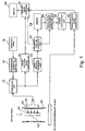
- FIG. 1 is a block diagram showing an overall structure of an ultrasonic diagnostic apparatus according to a preferred embodiment of the present invention
- FIG. 2 is a diagram schematically showing each echo signal
- FIG. 3 is a diagram for explaining tracking of a bone surface section by the echo signals
- FIG. 4 is a diagram for explaining the operation to cancel a translational displacement component
- FIG. 5 is a diagram showing a method of diagnosing the tibia using an ultrasonic diagnostic apparatus according to a preferred embodiment of the present invention
- FIG. 6 is a diagram showing a method of fixing a probe
- FIG. 7 is a diagram showing another method of fixing a probe
- FIG. 8 is a diagram showing another method of fixing a probe
- FIG. 9 is a diagram showing an example of a characteristic curve of a change with respect to time of load and strain, generated by a characteristic curve generator unit;
- FIG. 10 is a diagram showing an example of a characteristic curve showing a relationship between a load and strain, generated by a characteristic curve generator unit;
- FIG. 11 is a diagram showing another example of a characteristic curve showing a change with respect to time of a load and strain, generated by a characteristic curve generator unit.
- FIG. 12 is a diagram showing a hysteresis characteristic curve of a load and strain, generated by a characteristic curve generator unit.
- FIG. 1 shows a preferred embodiment of an ultrasonic diagnostic apparatus according to the present invention.
- FIG. 1 is a block diagram showing an overall structure of the ultrasonic diagnostic apparatus.
- a probe 10 is an ultrasonic probe used in contact with a surface of the body of a subject 50 .
- an ultrasonic probe which is inserted into the subject may be used.
- the probe 10 transmits and receives ultrasonic beams 40 to and from a bone 52 within the body of the subject 50 . Tracking points 42 which are set on the bone 52 will be described later.
- a linear electronic scan probe linear array probe
- a transceiver unit 12 controls the probe 10 and electronically scans the ultrasonic beam 40 on a cross sectional surface (a cut surface of a subject in FIG. 1 ).
- the probe 10 is a linear probe, for example, sequential electronic scanning of 120 ultrasonic beams 40 ( FIG. 1 only shows 4 ultrasonic beams for echo tracking which will be described later) is applied and an echo signal is obtained for each ultrasonic beam 40 .
- the plurality of obtained echo signals are output to a cross sectional image formation unit 18 and the cross sectional image formation unit 18 forms a cross sectional image (B mode image) of the bone based on the plurality of echo signals.
- the echo signal obtained in the transceiver unit 12 is also output to an echo tracking processor unit 20 .
- the echo tracking processor unit 20 applies an echo tracking process in which the bone surface section is extracted from each echo signal and is tracked.
- an echo tracking process for example, a technique detailed in Japanese Patent Laid-Open Publication No. 2001-309918 is used.
- 4 tracking echo signals are used for the echo tracking process.
- the tracking echo signals may be selected from among the echo signals used for forming a cross sectional image (for example, 120 echo signals) or may alternatively be obtained by interrupting formation of the cross sectional image and obtaining the 4 tracking echo signals.
- the 4 ultrasonic beams 40 shown in FIG. 1 correspond to the 4 tracking echo signals.
- An examiner inputs an instruction related to transmission/reception of the ultrasound through an operation panel 16 to a transmission/reception control unit 14 and the transmission/reception control unit 14 controls the transceiver unit 12 based on the instruction from the examiner.
- ultrasonic beams 40 for obtaining tracking echo signals are transmitted to a diagnosis site on the bone surface according to the instruction from the examiner.
- a strong reflected wave is obtained from the bone surface. Therefore, the echo signals obtained from within the body of the diagnosis target (subject) are obtained as having large amplitude in a portion corresponding to the bone surface.
- FIG. 2 is a diagram schematically showing a bone surface section of the echo signals.
- each echo signal includes a range 60 in which the echo signal has a large amplitude corresponding to the bone surface.
- the bone surface section is considered simply as a portion with a large amplitude, it is unclear as to which portion in the range 60 corresponds to the surface section and, as a result, there is an error of approximately the range 60 .
- a zero-cross point 62 is detected as a representative of each echo signal and the detected zero-cross point 62 is tracked to significantly increase the precision of the bone surface position.
- the zero-cross point 62 is detected as a time, within a tracking gate period 64 , at which the polarity of the echo signal is inverted from positive to negative or from negative to positive.
- the time at which the polarity of the echo signal is inverted from positive to negative is the zero-cross point 62 .
- a new tracking gate is set with the detected zero-cross point 62 as its center.
- a zero-cross point 62 is detected within the newly set tracking gate period 64 . In this manner, a zero-cross point 62 is tracked as the bone surface point for each echo signal.
- FIG. 3 is a diagram for explaining tracking of a bone surface section by 4 echo signals.
- a shape of the bone is compared between a state in which no load is applied to the bone (no-load state) and a state in which a load is applied (loaded state).
- FIG. 3 shows tracking in each of the no-load state and the loaded state.
- FIG. 3 (A) shows tracking with respect to the bone 52 in the no-load state.
- Echo signals 68 corresponding to 4 ultrasonic beams 40 applied toward the bone 52 indicate a large amplitude (an amplitude maximum portion 69 ) at a section corresponding to the bone surface. It is possible to know the shape of the bone surface based on the position of the amplitude maximum portion 69 in each echo signal 68 (obtained time of the waveform). Because the zero-cross point (reference numeral 62 in FIG. 2 ) is detected as a surface point within the amplitude maximum portion 69 , the position of the bone surface is very precisely identified.
- FIG. 3 (B) shows tracking with respect to the bone 52 in the loaded state. Similar to FIG. 3 (A), the shape of the bone surface can be known based on the echo signals 68 corresponding to the 4 ultrasonic beams 40 . Because a load is applied, strain (bending of bone) of the bone 52 in FIG. 3 (B) is larger than that in FIG. 3 (A). Although an example configuration with 4 tracking echo signals is shown in FIG. 3 , it is also possible to measure with a plurality of tracking echo signals, the number being different from 4.
- a surface point which is tracked for each echo signal, that is, for each ultrasonic beam 40 in the echo tracking processor unit 20 is the tracking point 42 .
- An interpolation line generator unit 22 generates an interpolation line connecting these tracking points 42 . That is, by interpolating with a curve among a plurality of tracking points 42 using a spline interpolation or a least square interpolation, an interpolation line is calculated. By increasing the number of echo signals for echo tracking process it is possible to more precisely approximate the surface shape of the bone by the interpolation line.
- an interpolation line is calculated considering the specific section. For example, when there is a fracture in the bone, it is possible to form interpolation lines for the portions of the bone separated by the bone fracture and to combine these two interpolation lines to form an interpolation line for the bone as a whole.
- the interpolation line is calculated for each time phase and is output to a memory 24 , a translational displacement corrector unit 26 , and a display image formation unit 32 .
- the translational displacement corrector unit 26 cancels a translational displacement component between an interpolation line corresponding to a time phase in the no-load state stored in the memory 24 and an interpolation line corresponding to a time phase in the loaded state output from the interpolation line generator unit 22 .
- FIG. 4 is a diagram for explaining a cancel operation of the translational displacement component in the translational displacement corrector unit 26 .
- the translational displacement corrector unit 26 overlaps the interpolation line corresponding to the no-load state (no-load-state interpolation line 70 ) and the interpolation line corresponding to the loaded state (loaded-state interpolation line 72 ) on each other to cancel the translational displacement component.
- the overlapping of the interpolation lines is performed, for example, by matching the ends of the no-load-state interpolation line 70 and the loaded-state interpolation line 72 .
- By performing the overlapping operation it is possible to cancel out the translational displacement between interpolation lines due to a movement of the bone during measurement.
- an amount of strain of the bone is very precisely extracted from a difference between the no-load-state interpolation line 70 and the loaded-state interpolation line 72 which are overlapped.
- a strain calculator unit 28 calculates an amount ⁇ of strain of the bone and outputs to a characteristic curve generator unit 30 .
- the characteristic curve generator unit 30 generates a characteristic curve regarding the strain of the bone based on a load value output by a load measurement device 36 and an amount of strain of bone output by the strain calculator unit 28 .
- FIG. 5 is a diagram showing a method for diagnosing the tibia using the ultrasonic diagnostic apparatus of FIG. 1 .
- a weight 92 is placed on the lap of a subject 90 who is sitting on a chair so that a load due to the weight 92 is applied to the tibia.
- the load value due to the weight 92 is measured by the load measurement device 36 and is output to a main system 100 of the ultrasonic diagnosis device.
- the probe 10 is fixed by a probe fixer which is not shown and transmits and receives ultrasound to and from the crus (a site of the tibia).
- FIG. 6 A positional relationship among the probe 10 , crus, and probe fixer is shown in FIG. 6 .
- the probe 10 is supported by a position adjuster device 102 which functions as a probe fixer and placed in a predetermined position.
- a load due to the weight 92 is applied to the crus 94 of the subject and the load value is measured by the load measurement device 36 .
- a standoff 106 is mounted on the crus 94 with a belt 104 .
- the standoff 106 is a gel-like medium which allows ultrasound to transmit through and has an acoustic impedance which is close to that of a living body.
- the probe 10 is placed in contact with the standoff 106 and transmits and receives ultrasound to and from the crus 94 of the subject via the standoff 106 , to evaluate the mechanical characteristics of the tibia or fibula.
- FIGS. 7 and 8 show other examples of methods for fixing the probe 10 .
- the probe 10 is placed in contact with the crus 94 using the belt 104 .
- the subject places the crus 94 in a water tank 112 and the probe 10 is fixed by an angle adjuster device 108 mounted on the water tank 112 .
- the probe 10 is covered by a thin film rubber sheet window 110 and transmits and receives ultrasound to and from the crus 94 via water.
- a fixing device which is not shown is provided so that the position of the crus 94 with respect to the probe 10 does not change.
- the load value due to the weight 92 is measured by a load measurement device 36 .
- FIGS. 9 and 10 show examples of characteristic curves generated by the characteristic curve generator unit 30 .
- FIG. 9 is a diagram showing each of a load value and an amount of strain of bone with the horizontal axis taken as an event (four stages of A, B, C, and D). It can be seen that, when the load value is increased stepwise in the order of events A, B, C, and D, the amount of strain of bone correspondingly increases in a stepwise manner.
- FIG. 10 is a diagram showing a relationship between the amount of strain of bone and the load value shown in FIG. 9 , with the horizontal axis representing the amount of strain of bone and the vertical axis representing the load value.
- FIG. 10 also shows an approximation line calculated with data discretely obtained in the four stages of A, B, C, and D.
- the characteristic curves shown in FIGS. 9 and 10 are displayed on a display (reference numeral 34 of FIG. 1 ) through a display image formation unit (reference numeral 32 of FIG. 1 ).
- the rigidity of the bone of the diagnosis target (subject) is normal when the value of B is within a predetermined range estimated from the value of A and that the rigidity of the bone of the diagnosis target is abnormal when the value of B is outside the range. It is also possible to evaluate the rigidity of the bone from a difference, (B ⁇ A).
- a weight load which is an external action to the bone and quantifying plastic deformation of the bone after the weight is removed.
- Other methods for applying a load to the tibia include standing on one foot, standing on both feet, and cycle load by walking.
- the load value can be measured by the load measurement device (reference numeral 36 in FIG. 1 ) similar to the above-described configuration.
- FIGS. 11 and 12 show examples of characteristic curves generated by the characteristic curve generator unit 30 in the case of a cycle load.
- FIG. 11 is a characteristic curve showing each of the load value and amount of strain of the bone with the horizontal axis representing time.
- FIG. 11 shows that when the load value is gradually increased from time 0 to time t, the amount of strain correspondingly gradually increases from time 0 to time t. It can also be seen that when the load value is gradually reduced after time t, the amount of strain is also gradually reduced.
- the characteristic curve of FIG. 11 is displayed on a display (reference numeral 34 in FIG. 1 ) through a display image formation unit (reference numeral 32 in FIG. 1 ). The examiner can read the amount of strain of the bone corresponding to a load value from the characteristic curve displayed on the display 34 .
- FIG. 12 shows a characteristic curve in which the horizontal axis represents an amount of strain of the bone and the vertical axis represents a load value. There is a hysteresis characteristic between the amount of load to the bone and the amount of strain of the bone. In other words, an increase characteristic of the amount of strain of the bone when the load value is gradually increased to the maximum load value and a decrease characteristic of the amount of strain of the bone when the load is gradually reduced from the maximum load value would not be the same curve.
- FIG. 12 shows a characteristic when the load value is increased to a maximum load value and then reduced from the maximum load value. The area of a region 80 reflects the hysteresis characteristic between the load value and the amount of strain.
- the characteristic curve shown in FIG. 12 is displayed on the display (reference numeral 34 of FIG. 1 ) through the display image formation unit (reference numeral 32 of FIG. 1 ).
- the display image formation unit 32 forms a display image based on the cross sectional image of the bone formed in the cross sectional image formation unit 18 and the characteristic curve generated by the characteristic curve generator unit 30 and displays the formed image on the display 34 .
- the cross sectional image and the characteristic curve are, for example, switched and displayed based on an instruction by the examiner. Alternatively, the cross sectional image and the characteristic curve may be simultaneously displayed. Moreover, it is also possible to display the interpolation line calculated by the interpolation line generator unit 22 , overlapped over the cross sectional image of the bone.
- the mechanical characteristic thus obtained such as the amount of strain or strength of bone is an important measure of a quantitative evaluation of bone union and significantly contributes as objective and reliable base data of diagnosis in judgment of effects by an agent to an increase in the bone strength, removal of a fixator/implant, and instruction of degree of load to a patient.
- the diagnosis target bone of the ultrasonic diagnostic apparatus is not limited to the tibia and the fibula, and may alternatively applied to, for example, femur and arm bones.
- femur When the femur is to be targeted, it is possible to place, on a load measurement device, a diagnosis target wrapping around a weight and diagnose with the probe contacting the femur, to measure the load value applied to the femur and the shape of the femur.
- the arm bones it is possible to contact the probe on the arm of the subject and to diagnose while the arm is loaded by the subject pushing, with the arm, a load measurement device mounted on a wall.
- the ultrasonic diagnostic apparatus of the present invention can be applied to the bones of various regions in the subject.
- a diagnosis using the ultrasonic diagnostic apparatus of the present invention is advantageous in that the diagnosis can be applied independent of the method of treatment of bone fracture.
- the ultrasonic diagnostic apparatus of the present invention it is possible to non-invasively and quantitatively evaluate a mechanical characteristic of the bone within a living body.
Abstract
Description
Claims (12)
Priority Applications (1)
| Application Number | Priority Date | Filing Date | Title |
|---|---|---|---|
| US10/951,322 US7806823B2 (en) | 2004-09-27 | 2004-09-27 | Ultrasonic diagnostic apparatus |
Applications Claiming Priority (1)
| Application Number | Priority Date | Filing Date | Title |
|---|---|---|---|
| US10/951,322 US7806823B2 (en) | 2004-09-27 | 2004-09-27 | Ultrasonic diagnostic apparatus |
Publications (2)
| Publication Number | Publication Date |
|---|---|
| US20060074311A1 US20060074311A1 (en) | 2006-04-06 |
| US7806823B2 true US7806823B2 (en) | 2010-10-05 |
Family
ID=36126473
Family Applications (1)
| Application Number | Title | Priority Date | Filing Date |
|---|---|---|---|
| US10/951,322 Active 2026-02-15 US7806823B2 (en) | 2004-09-27 | 2004-09-27 | Ultrasonic diagnostic apparatus |
Country Status (1)
| Country | Link |
|---|---|
| US (1) | US7806823B2 (en) |
Cited By (13)
| Publication number | Priority date | Publication date | Assignee | Title |
|---|---|---|---|---|
| US20100180684A1 (en) * | 2006-05-17 | 2010-07-22 | Raffaella Righetti | Methods For Measuring Mechanical Stimulus |
| US20110130688A1 (en) * | 2008-07-22 | 2011-06-02 | The University Of Tokyo | Bone inspecting system, and lower leg supporting device |
| US9579120B2 (en) | 2010-01-29 | 2017-02-28 | University Of Virginia Patent Foundation | Ultrasound for locating anatomy or probe guidance |
| US9726647B2 (en) | 2015-03-17 | 2017-08-08 | Hemosonics, Llc | Determining mechanical properties via ultrasound-induced resonance |
| US10368834B2 (en) | 2011-04-26 | 2019-08-06 | University Of Virginia Patent Foundation | Bone surface image reconstruction using ultrasound |
| US10426429B2 (en) | 2015-10-08 | 2019-10-01 | Decision Sciences Medical Company, LLC | Acoustic orthopedic tracking system and methods |
| US10743838B2 (en) | 2015-02-25 | 2020-08-18 | Decision Sciences Medical Company, LLC | Acoustic signal transmission couplants and coupling mediums |
| US10962524B2 (en) | 2011-02-15 | 2021-03-30 | HomoSonics LLC | Characterization of blood hemostasis and oxygen transport parameters |
| US10993699B2 (en) | 2011-10-28 | 2021-05-04 | Decision Sciences International Corporation | Spread spectrum coded waveforms in ultrasound diagnostics |
| US11096661B2 (en) | 2013-09-13 | 2021-08-24 | Decision Sciences International Corporation | Coherent spread-spectrum coded waveforms in synthetic aperture image formation |
| US11154274B2 (en) | 2019-04-23 | 2021-10-26 | Decision Sciences Medical Company, LLC | Semi-rigid acoustic coupling articles for ultrasound diagnostic and treatment applications |
| US11520043B2 (en) | 2020-11-13 | 2022-12-06 | Decision Sciences Medical Company, LLC | Systems and methods for synthetic aperture ultrasound imaging of an object |
| US11957516B2 (en) | 2023-02-27 | 2024-04-16 | Decision Sciences International Corporation | Spread spectrum coded waveforms in ultrasound diagnostics |
Families Citing this family (10)
| Publication number | Priority date | Publication date | Assignee | Title |
|---|---|---|---|---|
| DE102006018516A1 (en) * | 2006-04-21 | 2007-10-25 | Spahn, Frank-Peter, Dr. | Implant, in particular jaw implant, with different material properties |
| JP4247265B2 (en) * | 2006-10-10 | 2009-04-02 | アロカ株式会社 | Ultrasonic diagnostic equipment |
| US8187185B2 (en) * | 2007-08-08 | 2012-05-29 | Hitachi Aloka Medical, Ltd. | Ultrasound diagnostic apparatus |
| US9307951B2 (en) * | 2007-08-08 | 2016-04-12 | Hitachi Aloka Medical, Ltd. | Ultrasound diagnosis apparatus |
| JP4500336B2 (en) * | 2007-09-06 | 2010-07-14 | アロカ株式会社 | Ultrasonic diagnostic equipment |
| US7938778B2 (en) * | 2007-12-26 | 2011-05-10 | Aloka Co., Ltd. | Ultrasound diagnosis apparatus |
| EP2100558A1 (en) * | 2008-03-10 | 2009-09-16 | Aloka Co., Ltd. | Pressing mechanism and ultrasound diagnostic apparatus |
| US20090240145A1 (en) * | 2008-03-19 | 2009-09-24 | Aloka Co., Ltd. | Pressing mechanism and ultrasound diagnostic apparatus |
| JP4517090B2 (en) * | 2008-11-18 | 2010-08-04 | 国立大学法人 東京大学 | Ultrasonic diagnostic equipment |
| DE102010053449B4 (en) * | 2010-12-06 | 2013-04-18 | Wittenstein Ag | Device for determining bone conditions and method for operating the device |
Citations (17)
| Publication number | Priority date | Publication date | Assignee | Title |
|---|---|---|---|---|
| US5368044A (en) | 1989-10-24 | 1994-11-29 | The Adelaide Bone And Joint Research Foundation, Inc. | Vibrational analysis of bones |
| US5474070A (en) | 1989-11-17 | 1995-12-12 | The Board Of Regents Of The University Of Texas System | Method and apparatus for elastographic measurement and imaging |
| US5524636A (en) * | 1992-12-21 | 1996-06-11 | Artann Corporation Dba Artann Laboratories | Method and apparatus for elasticity imaging |
| EP0737441A1 (en) | 1995-04-10 | 1996-10-16 | Aloka Co., Ltd. | Bone assessment apparatus and method |
| JPH0984788A (en) | 1995-09-26 | 1997-03-31 | Aloka Co Ltd | Tissue structure analyzing device |
| US5678565A (en) | 1992-12-21 | 1997-10-21 | Artann Corporation | Ultrasonic elasticity imaging method and device |
| US6132376A (en) * | 1996-02-29 | 2000-10-17 | Acuson Corporation | Multiple ultrasonic image registration system, method and transducer |
| US6270459B1 (en) * | 1998-05-26 | 2001-08-07 | The Board Of Regents Of The University Of Texas System | Method for estimating and imaging of transverse displacements, transverse strains and strain ratios |
| JP2001309918A (en) | 2000-05-01 | 2001-11-06 | Aloka Co Ltd | Ultrasonic diagnostic device |
| US20020056312A1 (en) * | 1999-12-10 | 2002-05-16 | Sumitomo Chemical Company, Limited | Method and apparatus for detecting agglomerates |
| US20020103432A1 (en) * | 2001-01-31 | 2002-08-01 | Kawchuk Gregory N. | Non-invasive diagnostic method and apparatus for musculoskeletal systems |
| US20020157478A1 (en) * | 2001-04-26 | 2002-10-31 | Seale Joseph B. | System and method for quantifying material properties |
| US6520913B1 (en) * | 1998-05-29 | 2003-02-18 | Lorenz & Pesavento Ingenieurbüro für Informationstechnik | System for rapidly calculating expansion images from high-frequency ultrasonic echo signals |
| US20040234113A1 (en) * | 2003-02-24 | 2004-11-25 | Vanderbilt University | Elastography imaging modalities for characterizing properties of tissue |
| US20060120582A1 (en) * | 2003-06-26 | 2006-06-08 | Eastman Kodak Company | Method for determining dental alignment using radiographs |
| US20060184020A1 (en) * | 2001-12-21 | 2006-08-17 | Chikayoshi Sumi | Displacement measurement method and apparatus, strain measurement method and apparatus, elasticity and visco-elasticity constants measurement apparatus, and the elasticity and visco-elasticity constants measurement apparatus-based treatment apparatus |
| US7107159B2 (en) * | 2004-03-29 | 2006-09-12 | Peter Thomas German | Systems and methods to determine elastic properties of materials |
Family Cites Families (1)
| Publication number | Priority date | Publication date | Assignee | Title |
|---|---|---|---|---|
| TW499314B (en) * | 2000-05-30 | 2002-08-21 | Novo Nordisk As | A medication delivery device with replaceable cooperating modules and a method of making same |
-
2004
- 2004-09-27 US US10/951,322 patent/US7806823B2/en active Active
Patent Citations (17)
| Publication number | Priority date | Publication date | Assignee | Title |
|---|---|---|---|---|
| US5368044A (en) | 1989-10-24 | 1994-11-29 | The Adelaide Bone And Joint Research Foundation, Inc. | Vibrational analysis of bones |
| US5474070A (en) | 1989-11-17 | 1995-12-12 | The Board Of Regents Of The University Of Texas System | Method and apparatus for elastographic measurement and imaging |
| US5524636A (en) * | 1992-12-21 | 1996-06-11 | Artann Corporation Dba Artann Laboratories | Method and apparatus for elasticity imaging |
| US5678565A (en) | 1992-12-21 | 1997-10-21 | Artann Corporation | Ultrasonic elasticity imaging method and device |
| EP0737441A1 (en) | 1995-04-10 | 1996-10-16 | Aloka Co., Ltd. | Bone assessment apparatus and method |
| JPH0984788A (en) | 1995-09-26 | 1997-03-31 | Aloka Co Ltd | Tissue structure analyzing device |
| US6132376A (en) * | 1996-02-29 | 2000-10-17 | Acuson Corporation | Multiple ultrasonic image registration system, method and transducer |
| US6270459B1 (en) * | 1998-05-26 | 2001-08-07 | The Board Of Regents Of The University Of Texas System | Method for estimating and imaging of transverse displacements, transverse strains and strain ratios |
| US6520913B1 (en) * | 1998-05-29 | 2003-02-18 | Lorenz & Pesavento Ingenieurbüro für Informationstechnik | System for rapidly calculating expansion images from high-frequency ultrasonic echo signals |
| US20020056312A1 (en) * | 1999-12-10 | 2002-05-16 | Sumitomo Chemical Company, Limited | Method and apparatus for detecting agglomerates |
| JP2001309918A (en) | 2000-05-01 | 2001-11-06 | Aloka Co Ltd | Ultrasonic diagnostic device |
| US20020103432A1 (en) * | 2001-01-31 | 2002-08-01 | Kawchuk Gregory N. | Non-invasive diagnostic method and apparatus for musculoskeletal systems |
| US20020157478A1 (en) * | 2001-04-26 | 2002-10-31 | Seale Joseph B. | System and method for quantifying material properties |
| US20060184020A1 (en) * | 2001-12-21 | 2006-08-17 | Chikayoshi Sumi | Displacement measurement method and apparatus, strain measurement method and apparatus, elasticity and visco-elasticity constants measurement apparatus, and the elasticity and visco-elasticity constants measurement apparatus-based treatment apparatus |
| US20040234113A1 (en) * | 2003-02-24 | 2004-11-25 | Vanderbilt University | Elastography imaging modalities for characterizing properties of tissue |
| US20060120582A1 (en) * | 2003-06-26 | 2006-06-08 | Eastman Kodak Company | Method for determining dental alignment using radiographs |
| US7107159B2 (en) * | 2004-03-29 | 2006-09-12 | Peter Thomas German | Systems and methods to determine elastic properties of materials |
Cited By (23)
| Publication number | Priority date | Publication date | Assignee | Title |
|---|---|---|---|---|
| US20100180684A1 (en) * | 2006-05-17 | 2010-07-22 | Raffaella Righetti | Methods For Measuring Mechanical Stimulus |
| US20110130688A1 (en) * | 2008-07-22 | 2011-06-02 | The University Of Tokyo | Bone inspecting system, and lower leg supporting device |
| US8317710B2 (en) * | 2008-07-22 | 2012-11-27 | The University Of Tokyo | Bone inspecting system, and lower leg supporting device |
| US9579120B2 (en) | 2010-01-29 | 2017-02-28 | University Of Virginia Patent Foundation | Ultrasound for locating anatomy or probe guidance |
| US10962524B2 (en) | 2011-02-15 | 2021-03-30 | HomoSonics LLC | Characterization of blood hemostasis and oxygen transport parameters |
| US11680940B2 (en) | 2011-02-15 | 2023-06-20 | Hemosonics Llc | Characterization of blood hemostasis and oxygen transport parameters |
| US10368834B2 (en) | 2011-04-26 | 2019-08-06 | University Of Virginia Patent Foundation | Bone surface image reconstruction using ultrasound |
| US10993699B2 (en) | 2011-10-28 | 2021-05-04 | Decision Sciences International Corporation | Spread spectrum coded waveforms in ultrasound diagnostics |
| US11596388B2 (en) | 2011-10-28 | 2023-03-07 | Decision Sciences International Corporation | Spread spectrum coded waveforms in ultrasound diagnostics |
| US11096661B2 (en) | 2013-09-13 | 2021-08-24 | Decision Sciences International Corporation | Coherent spread-spectrum coded waveforms in synthetic aperture image formation |
| US11607192B2 (en) | 2013-09-13 | 2023-03-21 | Decision Sciences International Corporation | Coherent spread-spectrum coded waveforms in synthetic aperture image formation |
| US11191521B2 (en) | 2015-02-25 | 2021-12-07 | Decision Sciences Medical Company, LLC | Acoustic signal transmission couplants and coupling mediums |
| US10743838B2 (en) | 2015-02-25 | 2020-08-18 | Decision Sciences Medical Company, LLC | Acoustic signal transmission couplants and coupling mediums |
| US11839512B2 (en) | 2015-02-25 | 2023-12-12 | Decision Sciences Medical Company, LLC | Acoustic signal transmission couplants and coupling mediums |
| US11002712B2 (en) | 2015-03-17 | 2021-05-11 | Hemosonics Llc | Determining mechanical properties via ultrasound-induced resonance |
| US10495613B2 (en) | 2015-03-17 | 2019-12-03 | Hemosonics, Llc | Determining mechanical properties via ultrasound-induced resonance |
| US11656206B2 (en) | 2015-03-17 | 2023-05-23 | Hemosonics Llc | Determining mechanical properties via ultrasound-induced resonance |
| US9726647B2 (en) | 2015-03-17 | 2017-08-08 | Hemosonics, Llc | Determining mechanical properties via ultrasound-induced resonance |
| US10426429B2 (en) | 2015-10-08 | 2019-10-01 | Decision Sciences Medical Company, LLC | Acoustic orthopedic tracking system and methods |
| US11737726B2 (en) | 2015-10-08 | 2023-08-29 | Decision Sciences Medical Company, LLC | Acoustic orthopedic tracking system and methods |
| US11154274B2 (en) | 2019-04-23 | 2021-10-26 | Decision Sciences Medical Company, LLC | Semi-rigid acoustic coupling articles for ultrasound diagnostic and treatment applications |
| US11520043B2 (en) | 2020-11-13 | 2022-12-06 | Decision Sciences Medical Company, LLC | Systems and methods for synthetic aperture ultrasound imaging of an object |
| US11957516B2 (en) | 2023-02-27 | 2024-04-16 | Decision Sciences International Corporation | Spread spectrum coded waveforms in ultrasound diagnostics |
Also Published As
| Publication number | Publication date |
|---|---|
| US20060074311A1 (en) | 2006-04-06 |
Similar Documents
| Publication | Publication Date | Title |
|---|---|---|
| US7806823B2 (en) | Ultrasonic diagnostic apparatus | |
| EP1707124B1 (en) | Ultrasonic apparatus for diagnosing bone diseases | |
| US7938778B2 (en) | Ultrasound diagnosis apparatus | |
| JP3954981B2 (en) | Ultrasonic diagnostic equipment | |
| US6585649B1 (en) | Methods and devices for improving ultrasonic measurements using multiple angle interrogation | |
| US8419643B2 (en) | Ultrasonic method and apparatus for assessment of bone | |
| US20130237820A1 (en) | Devices, methods, and systems for measuring elastic properties of biological tissues | |
| US20090069683A1 (en) | Ultrasound diagnosis apparatus | |
| US6086538A (en) | Methods and apparatus for evaluation of bone condition | |
| WO2013153968A1 (en) | Ultrasonic diagnosis device | |
| JP4153407B2 (en) | Ultrasonic diagnostic equipment | |
| US7727152B2 (en) | Method and apparatus for scanning confocal acoustic diagnostic for bone quality | |
| US11490876B2 (en) | Ultrasonic diagnostic device and method for evaluating physical properties of biological tissue | |
| JP4381118B2 (en) | Ultrasonic diagnostic equipment | |
| US20090112094A1 (en) | Phased Apply Ultrasound With Electronically Controlled Focal Point For Assessing Bone Quality Via Acoustic Topology And Wave Transmit Functions | |
| EP1639946B1 (en) | Ultrasonic diagnostic apparatus | |
| JP4716792B2 (en) | Ultrasonic diagnostic equipment | |
| JP4627686B2 (en) | Ultrasonic diagnostic equipment | |
| JP4608458B2 (en) | Ultrasonic diagnostic equipment | |
| JP4517090B2 (en) | Ultrasonic diagnostic equipment | |
| JP2664628B2 (en) | Bone evaluation device for calcaneus | |
| Harada et al. | 2A-1 A New Method for Measuring Bone Strength using Echo-Tracking | |
| RU2302199C1 (en) | Method for investigating biomechanical joint properties | |
| JP2005095221A (en) | Ultrasonic osteometry apparatus and osteometry | |
| Sakai et al. | 12C-4 A Minute Bone Bending Angle Measuring Method Using Echo-Tracking for Assessment of Bone Strength |
Legal Events
| Date | Code | Title | Description |
|---|---|---|---|
| AS | Assignment |
Owner name: OHNISHI, ISAO, JAPAN Free format text: ASSIGNMENT OF ASSIGNORS INTEREST;ASSIGNORS:SAKAI, RYOICHI;HARADA, AKIMITSU;NAKAMURA, KOZO;AND OTHERS;REEL/FRAME:016100/0613 Effective date: 20041209 Owner name: NAKAMURA, KOZO, JAPAN Free format text: ASSIGNMENT OF ASSIGNORS INTEREST;ASSIGNORS:SAKAI, RYOICHI;HARADA, AKIMITSU;NAKAMURA, KOZO;AND OTHERS;REEL/FRAME:016100/0613 Effective date: 20041209 Owner name: ALOKA CO., LTD., JAPAN Free format text: ASSIGNMENT OF ASSIGNORS INTEREST;ASSIGNORS:SAKAI, RYOICHI;HARADA, AKIMITSU;NAKAMURA, KOZO;AND OTHERS;REEL/FRAME:016100/0613 Effective date: 20041209 |
|
| STCF | Information on status: patent grant |
Free format text: PATENTED CASE |
|
| AS | Assignment |
Owner name: HITACHI ALOKA MEDICAL, LTD., JAPAN Free format text: CHANGE OF NAME;ASSIGNOR:ALOKA CO., LTD.;REEL/FRAME:027595/0575 Effective date: 20110401 |
|
| FEPP | Fee payment procedure |
Free format text: PAYOR NUMBER ASSIGNED (ORIGINAL EVENT CODE: ASPN); ENTITY STATUS OF PATENT OWNER: LARGE ENTITY |
|
| FPAY | Fee payment |
Year of fee payment: 4 |
|
| AS | Assignment |
Owner name: HITACHI, LTD., JAPAN Free format text: ASSIGNMENT OF ASSIGNORS INTEREST;ASSIGNOR:HITACHI ALOKA MEDICAL, LTD.;REEL/FRAME:041891/0325 Effective date: 20160401 |
|
| MAFP | Maintenance fee payment |
Free format text: PAYMENT OF MAINTENANCE FEE, 8TH YEAR, LARGE ENTITY (ORIGINAL EVENT CODE: M1552) Year of fee payment: 8 |
|
| AS | Assignment |
Owner name: FUJIFILM HEALTHCARE CORPORATION, JAPAN Free format text: ASSIGNMENT OF ASSIGNORS INTEREST;ASSIGNOR:HITACHI, LTD.;REEL/FRAME:059018/0095 Effective date: 20220111 |
|
| MAFP | Maintenance fee payment |
Free format text: PAYMENT OF MAINTENANCE FEE, 12TH YEAR, LARGE ENTITY (ORIGINAL EVENT CODE: M1553); ENTITY STATUS OF PATENT OWNER: LARGE ENTITY Year of fee payment: 12 |