US7820313B2 - Fuel source recognition and gating apparatus and associated method - Google Patents
Fuel source recognition and gating apparatus and associated method Download PDFInfo
- Publication number
- US7820313B2 US7820313B2 US11/537,683 US53768306A US7820313B2 US 7820313 B2 US7820313 B2 US 7820313B2 US 53768306 A US53768306 A US 53768306A US 7820313 B2 US7820313 B2 US 7820313B2
- Authority
- US
- United States
- Prior art keywords
- fuel
- fuel container
- barrier
- retractable barrier
- gating
- Prior art date
- Legal status (The legal status is an assumption and is not a legal conclusion. Google has not performed a legal analysis and makes no representation as to the accuracy of the status listed.)
- Expired - Fee Related, expires
Links
Images


Classifications
-
- H—ELECTRICITY
- H01—ELECTRIC ELEMENTS
- H01M—PROCESSES OR MEANS, e.g. BATTERIES, FOR THE DIRECT CONVERSION OF CHEMICAL ENERGY INTO ELECTRICAL ENERGY
- H01M8/00—Fuel cells; Manufacture thereof
- H01M8/04—Auxiliary arrangements, e.g. for control of pressure or for circulation of fluids
- H01M8/04082—Arrangements for control of reactant parameters, e.g. pressure or concentration
- H01M8/04201—Reactant storage and supply, e.g. means for feeding, pipes
-
- H—ELECTRICITY
- H01—ELECTRIC ELEMENTS
- H01M—PROCESSES OR MEANS, e.g. BATTERIES, FOR THE DIRECT CONVERSION OF CHEMICAL ENERGY INTO ELECTRICAL ENERGY
- H01M16/00—Structural combinations of different types of electrochemical generators
- H01M16/003—Structural combinations of different types of electrochemical generators of fuel cells with other electrochemical devices, e.g. capacitors, electrolysers
-
- Y—GENERAL TAGGING OF NEW TECHNOLOGICAL DEVELOPMENTS; GENERAL TAGGING OF CROSS-SECTIONAL TECHNOLOGIES SPANNING OVER SEVERAL SECTIONS OF THE IPC; TECHNICAL SUBJECTS COVERED BY FORMER USPC CROSS-REFERENCE ART COLLECTIONS [XRACs] AND DIGESTS
- Y02—TECHNOLOGIES OR APPLICATIONS FOR MITIGATION OR ADAPTATION AGAINST CLIMATE CHANGE
- Y02E—REDUCTION OF GREENHOUSE GAS [GHG] EMISSIONS, RELATED TO ENERGY GENERATION, TRANSMISSION OR DISTRIBUTION
- Y02E60/00—Enabling technologies; Technologies with a potential or indirect contribution to GHG emissions mitigation
- Y02E60/30—Hydrogen technology
- Y02E60/50—Fuel cells
Definitions
- This invention relates generally to a device for identifying a fuel source, and upon identification allowing the fuel source access to an electronic device, and more specifically to a method and apparatus for recognizing a fuel source container, and upon recognition, opening a barrier to provide access to a fuel cell fuel input.
- a fuel cell produces electrical energy by converting hydrogen and oxygen into water, thereby releasing electrons. As long as the fuel cell has access to hydrogen and oxygen, the fuel cell will continue to generate power. Because oxygen is readily available in our environment, the only obstacle in fuel cell implementation is supplying a source of hydrogen. Hydrogen is very hard to store and transport, which limits its use with mobile devices.
- a reformer converts more common and more easily accessible gases, such as methanol, ethanol and natural gases, into the hydrogen the fuel cell needs to operate. These conversions and chemical processes occur within the fuel cell.
- One problem associated with fuel containers is the fact that there are many different fuel sources available for supplying a fuel cell with a source of hydrogen.
- Different electronic device manufactures may use different types of fuel cells, and thus different types of fuel, in their devices. For example some may elect to use methanol, while others may use ethanol. Because not all fuel cells are alike, the fuel used to refill them must be tailored specifically to match the fuel cell. If a fuel cell using a first source of hydrogen, for example methanol, was refilled with a fuel source distributing a second source of hydrogen, for example ethanol, the fuel cell may not produce electricity as effectively as if it had been refilled with the proper source of hydrogen.
- FIG. 1 illustrates one embodiment of a gating device.
- FIG. 2 illustrates one embodiment of an identification sensor comprising an impedance detector.
- FIG. 3 illustrates one embodiment of an identification sensor comprising a connectivity detector.
- FIG. 4 illustrates one embodiment of an identification sensor comprising a barcode reader.
- FIG. 5 illustrates one embodiment of an identification sensor comprising a memory reader.
- FIG. 6 illustrates one embodiment of an identification sensor comprising a radio-frequency identification device.
- FIG. 7 illustrates one embodiment of an identification sensor comprising a label reader.
- FIG. 8 illustrates one embodiment of a hybrid electronic device.
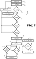
- FIG. 9 illustrates a method 900 of determining whether a fuel container is compatible with an electronic device.
- FIG. 10 illustrates one embodiment of the invention where the retractable barrier is in a partially closed position.
- Fuel cells are an up and coming energy source for mobile devices.
- mobile telephones will be used herein as exemplary electronic devices.
- liquid fueled devices such as devices employing an engine that is operational from a liquid fuel source
- hybrid devices such as devices having a fuel cell and battery power source
- other devices may employ the gating device of the present invention.
- the gating device 100 comprises a fuel container identification device 103 having an identification sensor 113 coupled thereto.
- the fuel container identification device 103 is configured to read, scan, or otherwise identify the fuel container identification 104 located on the fuel container 101 .
- a gating engine 105 powered in one embodiment by a battery 110 , is coupled to the fuel container identification device 103 .
- the fuel container identification device 103 recognizes the fuel container 101 by reading, scanning, or otherwise detecting indicia on the fuel container identification 104 .
- the gating engine 105 opens a retractable barrier 106 , thereby allowing the fuel container 101 to engage a fuel input 112 .
- the retractable barrier 106 prevents a fuel container coupling 111 connected to the fuel container 101 from accessing a fuel input 112 connected to the fuel cell 102 .
- the retractable barrier 106 comprises a sliding partition 107 .
- Other barriers including rotating shutters, pivoting partitions, cat's eye shutters, and the like may also control the coupling of the fuel container 101 with the fuel cell 102 .
- the sliding partition 107 is loaded with a spring 108 so as to be disposed in a closed position when the gating engine 105 is inactive.
- the gating engine 105 does not need to constantly exert energy in closing the sliding partition 107 .
- the gating engine 105 only needs to exert energy when opening the sliding partition 107 .
- the gating engine 105 may additionally include an electromechanical solenoid 109 , used to open the sliding partition 107 .
- the invention is not limited to the use of solenoid devices.
- Other gating engines, including pneumatic solenoids, hydraulic solenoids, electric motors, and the like may also be used to open the sliding partition 107 .
- an identification sensor 213 comprises an impedance detector 201 .
- an impedance detector may be used to identify a certain kind of a device using a voltage divider circuit.
- the voltage generated by a resistor divider network including a pull-up resistor and a pull-down resistor may be used to identify a power source.
- the impedance detector 201 may include a sensing element such as a pull-up resistor tied to power source.
- the fuel container 101 comprises a specific pull down resistor.
- a voltage at the meeting point is created. If the voltage does not match the voltage sought by impedance detector 201 , the retractable barrier 106 would remain in the closed position. In the event the voltage does match, the retractable barrier 106 would move to an open position.
- the identification sensor 313 comprises a connectivity detector 301 .
- the connectivity detector 301 identifies the fuel container identification 104 by way of a connectivity identifier 302 .
- the connectivity identifier 302 may be a label having apertures therein that expose electrically conductive portions of the fuel container 101 .
- the connectivity identifier 302 may be a label having an electric conductors disposed thereon in a specific pattern.
- the connectivity detector 301 can determine whether the orientation of its electrodes 304 corresponds to the specific pattern of electric surfaces 303 occurring on the connectivity identifier 302 .
- the sliding partition 107 In the event the specific pattern of electric surfaces 303 does not correspond to the orientation of the electrodes 304 , the sliding partition 107 would remain in the closed position. In the event the specific pattern of electric surfaces 303 matches the orientation of the electrodes 304 , the sliding partition 107 would move to an open position.
- the identification sensor 413 comprises a barcode reader 401 .
- the workings of a barcode reader 401 for identification will be clear to those of ordinary skill in the art.
- the barcode reader 401 reads the fuel container identification barcode 402 .
- the fuel container identification barcode 402 may include different types of information, such as a fuel container manufacturer, a fuel expiration date, a type of fuel container, and a type of fuel.
- identification sensor 513 comprises a memory reader 501 .
- a memory reader 501 may include a one-wire memory such as those made by Dallas Semiconductor Corporation. These devices are programmable semiconductor memories that are accessed using two electrical connections: (1) power/data and (2) ground. Since these are in fact memory devices, they may be used to obtain serial numbers and other information.
- the memory reader 501 may be used to access the fuel container identification 104 where the fuel container identification 104 comprises a memory device 502 . Where the memory device 502 indicates that the fuel container 101 is not compatible with the fuel cell ( 102 ), the sliding partition 107 would remain in the closed position. Where the memory device 502 indicates that the fuel container 101 is compatible with the fuel cell ( 102 ), the sliding partition 107 would move to an open position.
- FIG. 6 illustrated therein is an embodiment of an identification sensor suitable for use with the invention where the identification sensor 613 comprises a radio-frequency identification device 601 .
- Radio-frequency identification technology is well know by those in the art and is taught by U.S. Pat. No. 4,075,632 to Baldwin et al., issued Feb. 21, 1978, entitled “Interrogation, and detection system.”
- the radio-frequency identification device 601 may send a radio wave directed at the fuel container identification 104 where the fuel container identification 104 includes a radio-frequency identification tag 602 and a corresponding radio-frequency identification tag number.
- the radio-frequency identification tag 602 receives the radio wave and uses it to transmit the radio-frequency identification tag number.
- the sliding partition 107 In the event the radio-frequency identification tag number identifies a fuel container 101 not compatible with the fuel cell 102 , the sliding partition 107 would remain in the closed position. In the event the radio-frequency identification tag number identifies a fuel container 101 compatible with the fuel cell 102 , the sliding partition 107 would move to an open position.
- FIG. 7 illustrated therein is another embodiment of an identification sensor suitable for use with the invention in which the identification sensor 713 comprises a label reader 701 .
- U.S. Pat. No. 6,341,176 to Shirasaki et al., issued Jan. 22, 2002, entitled “Method and apparatus for character recognition” teaches a method and an apparatus for character recognition used when a document, such as a printed document, a hand-written document, or the like, is converted into text data.
- the label reader 701 may perform this task when reading the fuel container identification 104 where the fuel cell identification includes printed writing or text.
- the label reader 701 reads the label readable identification 702 .
- the label readable information 702 identifies a fuel container 101 not compatible with the fuel cell 102
- the sliding partition 107 would remain in the closed position.
- the label readable information 702 identifies a fuel container 101 compatible with the fuel cell 102
- the sliding partition 107 would move to an open position.
- the label reader 701 may have the ability to read fuel container identification comprising any combination of the following: a fuel container manufacture, a fuel expiration date, a type of fuel container, and a type of fuel. Additionally, other information may also be included.
- FIG. 8 illustrated therein is one embodiment of a hybrid electronic device 801 having a power source 802 that includes a fuel cell 102 and a battery 110 .
- the fuel cell 102 and battery 110 may be used in tandem to power the hybrid electronic device 801 .
- the battery is only used when the fuel cell runs out of fuel, or when no fuel is present. In this situation, the battery may be used to power components used to facilitate devices and methods described herein, such as the electromechanical solenoid 109 .
- the fuel cell 102 receives fuel from a fuel input 112 .
- the fuel input 112 is an interface having an opening for fuel to flow from a fuel container 101 into the fuel cell 102 .
- the hybrid electronic device 801 includes a fuel container identification device 103 for identifying fuel containers that are compatible with the fuel cell 102 .
- the fuel container identification device 103 includes a control circuit 803 .
- the control circuit 803 may receive information from the fuel container identification device 103 relating to the fuel container. Based on the content of the received information, the control circuit 803 may send signals to other components within the hybrid electronic device 801 with instructions on how to perform.
- the control circuit 803 may be used to communicate with a barrier retractor 804 .
- the barrier retractor 804 is a device capable of imbuing a force on an object. Such devices capable of imbuing a force on an object include solenoids, electric motors and hydraulic motion systems.
- the barrier retractor 804 comprises an electromechanical solenoid 109 .
- the electromechanical solenoid 109 uses a magnetic force, induced by electrifying a plurality of wire loops, to control the motion of a magnetic metal rod. Based on the direction of the magnetic field, the metal rod moves in respective relation to the electromechanical solenoid 109 .
- a retractable barrier 106 is operable with the barrier retractor 804 .
- the retractable barrier 106 is a rigid barrier shaped to prevent any access to the fuel input 112 when closed.
- the rigid barrier may be manufactured from a variety of substantially impervious materials including plastics, metals, ceramics and organic materials. Access to the fuel input 112 is granted when the retractable barrier 106 is moved to an open position by the barrier retractor 804 .
- the barrier retractor 804 moves the retractable barrier 106 to an open position when the fuel container identification device 103 identifies a fuel container 101 .
- the fuel container 101 is first inserted into the hybrid electronic device 801 .
- the fuel container identification device 103 comprises a barcode reader ( 401 ) and correspondingly, the fuel container identification 104 is a fuel container identification barcode ( 402 ).
- the fuel container 101 is initially blocked from gaining access to the fuel input 112 by the retractable barrier 106 being biased in a closed position.
- the barcode reader ( 401 ) reads the fuel container identification barcode ( 402 ) located on the fuel container 101 .
- the barcode reader ( 401 ) sends the retrieved data from the fuel container identification barcode ( 402 ) to the control circuit 803 .
- the control circuit 803 analyzes the retrieved data to see if it corresponds to compatible fuel usable with the fuel cell 102 . If the fuel within the fuel container 101 is deemed compatible by the control circuit 803 , the control circuit 803 directs the barrier retractor 804 to bias the retractable barrier 106 in an open position. Upon the retractable barrier 106 being biased in an open position, the fuel container can access the fuel input 112 and commence supplying the fuel cell 102 with fuel.
- the barrier retractor 804 may further be loaded with a spring 108 .
- the spring 108 may load the retractable barrier 106 in a closed position when the gating engine 105 is inactive. As such, the only time the retractable barrier 106 is open is when the barrier retractor 804 is active.
- the fuel container identification device 103 may be any of an impedance detector 201 , a connectivity detector 301 , a barcode reader 401 , a memory reader 501 , a radio-frequency identification device 601 , or a label reader 701 .
- other types of fuel container identification devices will be obvious to those of ordinary skill in the art. Designers have a large flexibility in choosing which fuel identification sensor to use. These decisions might be based upon, but not limited to, device housing size, device power requirements, already in use fuel container identification systems, and the sensing environment.
- a temperature sensor 805 is coupled to the control circuit 803 .
- the temperature sensor 805 may be configured to prevent the barrier retractor 804 from moving the retractable barrier 106 to an open position when the temperature sensor 805 detects an unacceptable temperature of either the fuel container 101 , the hybrid electronic device 801 , or the fuel cell 102 .
- the control circuit 803 prevents the barrier retractor 804 from opening the retractable barrier 106 when the temperature sensor 805 detects that a temperature associated with the fuel cell 102 or the fuel container 101 exceeds a predetermined temperature threshold.
- the reformers may need to be maintained above a certain temperature. If the environment is too cold, it may inhibit the reformers from breaking down the fuel; such instance would require a low-end temperature threshold to be maintained.
- the control circuit 803 prevents the barrier retractor 804 from opening the retractable barrier 106 when the temperature sensor 805 detects that a temperature associated with the fuel cell 102 or the fuel container 101 that is lower than a predetermined temperature threshold.
- a moisture sensor 806 is coupled to the control circuit 803 .
- the moisture sensor 806 may be configured to prevent the barrier retractor 804 from moving the retractable barrier 106 to an open position upon sensing moisture in excess of a predetermined moisture threshold. For example, in a highly humid environment, water particles might reside on the fuel container 101 . These water particles when in contact with the fuel input 112 may damage, or otherwise contaminate the fuel cell. Further, the moisture sensor 806 may also detect moisture residing within the hybrid electronic device. By way of an example, if the fuel cell is flooded with excess fuel, it may be inadvisable to add additional fuel to the fuel cell 102 .
- the moisture sensor 806 upon sensing the moisture in the form of flooded fuel, would inform the control circuit 803 .
- the control circuit 803 in turn would keep the retractable barrier 106 biased in a closed position thereby restricting access to the fuel input 112 .
- This predetermined moisture threshold might be set to a moisture amount wherein fuel stored in the fuel container 101 and the fuel cell 102 would react unfavorably if in contact with the moisture.
- One embodiment of the invention further comprises a touch sensor 813 attached to the fuel input 112 , whereupon being actuated when the fuel container 101 couples with the fuel input 112 .
- the actuation of this touch sensor 813 which is coupled to the control circuit 803 , causes the retractable barrier 106 to become biased in a closed position, for example, once the fuel container 101 has been identified and the retractable barrier 106 becomes biased in an open position allowing access to the fuel input 112 .
- the touch sensor 813 is actuated and causes the retractable barrier 106 to become biased in a closed position. This embodiment limits the amount of time the retractable barrier 106 is left biased in the open position.
- the barrier retractor 804 may comprise the electromechanical solenoid 109 .
- the electromechanical solenoid 109 When a fuel container 101 is identified, power is sent to the electromechanical solenoid 109 to bias the retractable barrier 106 in an open position. Continuous power must be supplied to the electromechanical solenoid 109 in order to keep the retractable barrier 106 biased in the open position.
- the use of a touch sensor 813 limits the amount of energy used to power the electromechanical solenoid 109 by closing the retractable barrier 106 after a coupling has been achieved.
- the control circuit 803 comprises a timer 807 .
- the timer 807 provides a temporal relation to the process of allowing the fuel container 101 access to the fuel cell 102 .
- the timer 807 may be configured to actuate upon the barrier retractor 804 causing the retractable barrier 106 to move from the closed position to the open position. This actuation might be caused by the fuel container identification device 103 identifying a fuel container 101 and providing the fuel container 101 with access to the fuel input 112 .
- the barrier retractor 804 upon expiration of the timer 807 , might be configured to cause the retractable barrier 106 to move from an open position to a closed position.
- the timer 807 further limits the time the retractable barrier 106 is biased in the open position.
- a timer can be illustrated in the case of a fuel container being identified and then immediately removed when only using a touch sensor 813 to close the retractable barrier 106 as described above.
- the retractable barrier 106 Once the fuel container 101 is identified the retractable barrier 106 is opened, it remains open since the fuel container is removed without making contact with the touch sensor.
- the retractable barrier 106 being biased in the open position without a coupled fuel container may allow debris to deposit on the fuel input 112 , possibly causing contamination.
- the use of a timer 807 would therefore limit the amount of time the fuel input 112 would be accessible to debris and other foreign materials.
- the timer 807 is actuated upon the retractable barrier 106 opening and would close the retractable barrier 106 after the timer 807 expires with no consideration of fuel container 101 fuel cell 102 coupling.
- FIG. 10 illustrated therein is one embodiment of the invention where the fuel container 101 is in contact with the fuel input 112 and may be refueling the fuel cell 102 .
- the embodiment illustrated in FIG. 10 further shows the retractable barrier 106 in a partially closed position, biased against the fuel container 101 following the expiration of the timer ( 807 ).
- the retractable barrier 106 may move to a fully closed position, as shown in FIG. 8 .
- the hybrid electronic device 801 comprises a communication circuit 808 coupled to the control circuit 803 .
- the communication circuit 808 may be configured to, upon the fuel container identification device 103 failing to identify the fuel container 101 , provide a fuel container notification 809 to a user, a service supplier, or a manufacturer.
- the communication circuit may not only provide fuel container notification locally, but may also send out the fuel container notification 809 to a remote destination. Communication with a remote user might be desirable in collecting statistics on fuel cell compatibility, type of fuel cells being used, and reasons of incompatibility.
- the control circuit 803 then lets the communication circuit 808 know of an unidentifiable fuel container and proceeds to send the communication circuit 808 any additional data sent by the fuel container identification device 103 concerning the fuel container 101 , such as manufacturer, expiration date, and other fuel container properties.
- the communication circuit 808 Upon receiving notification of an unidentifiable fuel container, the communication circuit 808 sends the fuel container notification 809 to a display 811 comprised within the hybrid electronic device 801 .
- the fuel container notification may be shown on the display 811 in the form of a message stating “Error in Identifying Fuel Container.”
- the hybrid electronic device 801 comprises a maintenance timer 810 .
- the maintenance timer 810 might be configured to determine a number of retractable barrier openings. Monitoring the number of times the retractable barrier 106 opens may be desired to provide a maintenance notification 812 to a user upon the number of retractable barrier openings exceeding a predetermined barrier opening threshold.
- the predetermined number of barrier openings threshold may be a number of retractable barrier openings which correspond to the hybrid electronic device 801 requiring maintenance.
- This maintenance notification 812 may be presented to the user on the display 811 .
- a maintenance notification upon the number of retractable barrier openings exceeding the predetermined barrier opening threshold might comprise the message “Maintenance Required.”
- FIG. 9 illustrated therein is one embodiment of a method 900 of determining whether a fuel container is compatible with an electronic device in accordance with the invention.
- the initial state of the device at step 901 , provides a retractable barrier disposed in a closed position. With the retractable barrier is disposed in a closed position, contact with the fuel cell input is prohibited, thereby protecting it from contamination.
- a fuel container is inserted into a fuel opening an electronic device.
- the fuel container may only travel in until it contacts the closed barrier.
- the electronic device attempts to identify the fuel container, at decision 903 . If the fuel container is not recognized, in one embodiment, at step 904 a notification is sent to a user explaining that the fuel container could not be identified. Following the notification, at step 905 , the retractable barrier remains disposed in a closed position.
- the step of determining compatibility includes a test determining whether the fuel contained in the fuel container is compatible with the fuel cell disposed within the electronic device.
- the step of determining compatibility may include a temperature verification. This verification involves measuring a temperature, wherein the compatibility test is overcome if the temperature is above or below a predetermined temperature threshold.
- the temperature measured in this test can include temperature of the fuel container, the fuel, the fuel cell, or the electronic device.
- the step of determining compatibility may include a moisture compatibility test.
- a moisture detector may detect an amount of moisture present upon the fuel container or within the electronic device. If, for example, the moisture detected is below a predetermined moisture threshold, the fuel container may be deemed compatible with the electronic device.
- compatibility test may optionally be used to verify that the fuel container is compatible with the electronic device.
- compatibility is determined by performing a temporal test on the fuel container.
- a temporal characteristic may be any type of time-based information relating to the fuel container, including for example an expiration date or warranty period.
- This compatibility test may determine whether the temporal characteristic of the fuel container is with a predetermined time of use window. For example, a control circuit in the device may test to determine if the current date is beyond the expiration date of the fuel container. If the temporal characteristic is within the predetermined time of use window, the container may be deemed compatible with the device.
- compatibility tests may also employed without departing from the scope and spirit of the invention.
- Other exemplary compatibility tests used to determine the whether a fuel container is compatible with an electronic device might include a coupling interface test, a pressure test, a size test, and other such tests.
- the various compatibility tests may be used in different combinations depending upon design choice and application. Some devices may employ three or four compatibility tests, while other devices may employ only one or two.
- the fuel container may be deemed incompatible with the device.
- the retractable barrier remains closed.
- the fuel container may be deemed compatible and the retractable barrier opened at step 907 , thus giving the fuel container access to the fuel input.
- the maintenance timer may be incremented at step 908 .
- a maintenance timer is employed, at decision 909 the maintenance timer is compared to a predetermined barrier opening threshold. If the maintenance timer is within the predetermined barrier opening threshold, the method continues directly to step 911 . If the maintenance timer exceeds the predetermined barrier opening threshold, a notification may be sent to a user explaining that the electronic device is in need of maintenance at step 910 . In one embodiment, once the notification is sent, the retractable barrier is closed, and will remain so until maintenance is preformed.
- a timer is initialized in response to the opening of the retractable barrier.
- the retractable barrier remains open until the timer expires, as determined at decision 912 .
- the retractable barrier is closed at step 914 . Closing the timer after a set time period may decrease the chance of foreign materials accessing the fuel input.
- the retractable barrier disposed in a closed position resting against the fuel container. Once the fuel container is removed, the retractable barrier moves to a full closed position.
- a further embodiment on biasing the retractable barrier in a closed position is that of using a touch switch.
- the touch switch may be located on the fuel input and actuated upon the fuel container making contact with the fuel input.
- the retractable barrier remains biased in an open position until the touch sensor is actuated at step 913 . Once the touch sensor is actuated, the retractable barrier is closed at step 914 .
- the use of a touch sensor decreases the amount of time the retractable barrier is left biased in an open position, and thus decreases power consumption as well as probability of debris contamination.
Landscapes
- Life Sciences & Earth Sciences (AREA)
- Engineering & Computer Science (AREA)
- Sustainable Development (AREA)
- Sustainable Energy (AREA)
- Chemical & Material Sciences (AREA)
- Chemical Kinetics & Catalysis (AREA)
- Electrochemistry (AREA)
- General Chemical & Material Sciences (AREA)
- Manufacturing & Machinery (AREA)
- Fuel Cell (AREA)
Abstract
Description
Claims (14)
Priority Applications (1)
| Application Number | Priority Date | Filing Date | Title |
|---|---|---|---|
| US11/537,683 US7820313B2 (en) | 2006-10-02 | 2006-10-02 | Fuel source recognition and gating apparatus and associated method |
Applications Claiming Priority (1)
| Application Number | Priority Date | Filing Date | Title |
|---|---|---|---|
| US11/537,683 US7820313B2 (en) | 2006-10-02 | 2006-10-02 | Fuel source recognition and gating apparatus and associated method |
Publications (2)
| Publication Number | Publication Date |
|---|---|
| US20080081234A1 US20080081234A1 (en) | 2008-04-03 |
| US7820313B2 true US7820313B2 (en) | 2010-10-26 |
Family
ID=39283725
Family Applications (1)
| Application Number | Title | Priority Date | Filing Date |
|---|---|---|---|
| US11/537,683 Expired - Fee Related US7820313B2 (en) | 2006-10-02 | 2006-10-02 | Fuel source recognition and gating apparatus and associated method |
Country Status (1)
| Country | Link |
|---|---|
| US (1) | US7820313B2 (en) |
Cited By (10)
| Publication number | Priority date | Publication date | Assignee | Title |
|---|---|---|---|---|
| WO2013112459A1 (en) * | 2012-01-27 | 2013-08-01 | Intelligent Energy Limited | Key verification of replaceable fuel cartridges |
| US20140174588A1 (en) * | 2012-12-21 | 2014-06-26 | Hyundai Motor Company | Contaminated hydrogen charging preventing system |
| US8783303B2 (en) | 2010-04-21 | 2014-07-22 | Ryan HARTY | Method and system for tank refilling |
| US9212783B2 (en) | 2010-04-21 | 2015-12-15 | Honda Motor Co., Ltd. | Method and system for tank refilling |
| US9347612B2 (en) | 2010-04-21 | 2016-05-24 | Honda Motor Co., Ltd. | Method and system for tank refilling using active fueling speed control |
| US9347614B2 (en) | 2010-04-21 | 2016-05-24 | Honda Motor Co., Ltd. | Method and system for tank refilling using active fueling speed control |
| US9605804B2 (en) | 2010-04-21 | 2017-03-28 | Honda Motor Co., Ltd. | Method and system for tank refilling using active fueling speed control |
| US10077998B2 (en) | 2015-09-14 | 2018-09-18 | Honda Motor Co., Ltd. | Hydrogen fueling with integrity checks |
| US11313514B2 (en) | 2018-12-04 | 2022-04-26 | Honda Motor Co., Ltd. | Method and system for tank refueling using dispenser and nozzle readings |
| US11339926B2 (en) | 2018-12-05 | 2022-05-24 | Honda Motor Co., Ltd. | Methods and systems for improving hydrogen refueling |
Families Citing this family (3)
| Publication number | Priority date | Publication date | Assignee | Title |
|---|---|---|---|---|
| FI20096149A0 (en) * | 2009-11-06 | 2009-11-06 | Senfit Oy | Humidity measurement |
| SG11201404224XA (en) | 2012-01-19 | 2014-08-28 | Intelligent Energy Ltd | Remote authentication of replaceable fuel cartridge |
| US20140261137A1 (en) * | 2013-03-14 | 2014-09-18 | Meridian Ocean Services | System and method for remote inspection of liquid filled structures |
Citations (9)
| Publication number | Priority date | Publication date | Assignee | Title |
|---|---|---|---|---|
| US20040265671A1 (en) * | 2003-06-27 | 2004-12-30 | Nokia Corporation | Fuel supply device and fuel supply system |
| US20050040951A1 (en) | 2000-09-29 | 2005-02-24 | Zalewski Thomas W. | Electronic device cover with embedded radio frequency (RF) reader and method of using same |
| US20050074656A1 (en) * | 2003-10-03 | 2005-04-07 | Hitachi Maxell, Ltd. | Fuel cell, electronic appliance and business method |
| US20060008687A1 (en) * | 2003-06-27 | 2006-01-12 | Ultracell Corporation | Fuel cell system internal to portable computer |
| US20060019135A1 (en) | 2003-12-01 | 2006-01-26 | Curello Andrew J | Fuel cell with fuel monitoring system and method of use |
| US20060222913A1 (en) * | 2005-03-30 | 2006-10-05 | Kabushiki Kaisha Toshiba | Communication terminal, power supply management system of the same, and charging method at the time of purchasing fuel reservoir |
| US7171989B2 (en) * | 2003-10-31 | 2007-02-06 | Cellex Power Products, Inc. | Fuel dispensing system and method |
| US20080077802A1 (en) * | 2003-06-27 | 2008-03-27 | Ultracell Corporation | Fuel cartridge authentication |
| US20080145739A1 (en) * | 2003-07-29 | 2008-06-19 | Societe Bic | Fuel Supply Systems Having Operational Resistance |
Family Cites Families (1)
| Publication number | Priority date | Publication date | Assignee | Title |
|---|---|---|---|---|
| CN1327279C (en) * | 2002-02-04 | 2007-07-18 | 夏普株式会社 | Liquid crystal display and method of manufacturing the same |
-
2006
- 2006-10-02 US US11/537,683 patent/US7820313B2/en not_active Expired - Fee Related
Patent Citations (11)
| Publication number | Priority date | Publication date | Assignee | Title |
|---|---|---|---|---|
| US20050040951A1 (en) | 2000-09-29 | 2005-02-24 | Zalewski Thomas W. | Electronic device cover with embedded radio frequency (RF) reader and method of using same |
| US20040265671A1 (en) * | 2003-06-27 | 2004-12-30 | Nokia Corporation | Fuel supply device and fuel supply system |
| US20060008687A1 (en) * | 2003-06-27 | 2006-01-12 | Ultracell Corporation | Fuel cell system internal to portable computer |
| US20080077802A1 (en) * | 2003-06-27 | 2008-03-27 | Ultracell Corporation | Fuel cartridge authentication |
| US20080145739A1 (en) * | 2003-07-29 | 2008-06-19 | Societe Bic | Fuel Supply Systems Having Operational Resistance |
| US20050074656A1 (en) * | 2003-10-03 | 2005-04-07 | Hitachi Maxell, Ltd. | Fuel cell, electronic appliance and business method |
| US7171989B2 (en) * | 2003-10-31 | 2007-02-06 | Cellex Power Products, Inc. | Fuel dispensing system and method |
| US20060019135A1 (en) | 2003-12-01 | 2006-01-26 | Curello Andrew J | Fuel cell with fuel monitoring system and method of use |
| US7642742B2 (en) * | 2003-12-01 | 2010-01-05 | Societe Bic | Fuel cell system with fuel supply monitoring system and method of use |
| US20060222913A1 (en) * | 2005-03-30 | 2006-10-05 | Kabushiki Kaisha Toshiba | Communication terminal, power supply management system of the same, and charging method at the time of purchasing fuel reservoir |
| US7729960B2 (en) * | 2005-03-30 | 2010-06-01 | Kabushiki Kaisha Toshiba | Communication terminal, power supply management system of the same, and charging method at the time of purchasing fuel reservoir |
Cited By (13)
| Publication number | Priority date | Publication date | Assignee | Title |
|---|---|---|---|---|
| US9347612B2 (en) | 2010-04-21 | 2016-05-24 | Honda Motor Co., Ltd. | Method and system for tank refilling using active fueling speed control |
| US9605804B2 (en) | 2010-04-21 | 2017-03-28 | Honda Motor Co., Ltd. | Method and system for tank refilling using active fueling speed control |
| US8783303B2 (en) | 2010-04-21 | 2014-07-22 | Ryan HARTY | Method and system for tank refilling |
| US9347614B2 (en) | 2010-04-21 | 2016-05-24 | Honda Motor Co., Ltd. | Method and system for tank refilling using active fueling speed control |
| US9212783B2 (en) | 2010-04-21 | 2015-12-15 | Honda Motor Co., Ltd. | Method and system for tank refilling |
| US9222620B2 (en) | 2010-04-21 | 2015-12-29 | Honda Motor Co., Ltd. | Method and system for tank refilling |
| US9111124B2 (en) | 2012-01-27 | 2015-08-18 | Intelligent Energy Limited | Key verification of replaceable fuel cartridges |
| WO2013112459A1 (en) * | 2012-01-27 | 2013-08-01 | Intelligent Energy Limited | Key verification of replaceable fuel cartridges |
| US20140174588A1 (en) * | 2012-12-21 | 2014-06-26 | Hyundai Motor Company | Contaminated hydrogen charging preventing system |
| US10077998B2 (en) | 2015-09-14 | 2018-09-18 | Honda Motor Co., Ltd. | Hydrogen fueling with integrity checks |
| US10782173B2 (en) | 2015-09-14 | 2020-09-22 | Honda Motor Co., Ltd. | Hydrogen fueling with integrity checks |
| US11313514B2 (en) | 2018-12-04 | 2022-04-26 | Honda Motor Co., Ltd. | Method and system for tank refueling using dispenser and nozzle readings |
| US11339926B2 (en) | 2018-12-05 | 2022-05-24 | Honda Motor Co., Ltd. | Methods and systems for improving hydrogen refueling |
Also Published As
| Publication number | Publication date |
|---|---|
| US20080081234A1 (en) | 2008-04-03 |
Similar Documents
| Publication | Publication Date | Title |
|---|---|---|
| US7820313B2 (en) | Fuel source recognition and gating apparatus and associated method | |
| US10497289B2 (en) | Reusable bolt electronic seal module with GPS/cellular phone communications and tracking system | |
| CN104011776B (en) | Electromechanical lock and the method being used for operating electromechanical lock | |
| EP2744296B1 (en) | Method and terminal for managing rfid card | |
| US20100210300A1 (en) | Communication device comprising a battery and a near-field communication module | |
| AU2019257390B2 (en) | Recyclable logistic appliance and method and system for processing empty and full signals thereof | |
| US20200372318A1 (en) | Container arrangement including a wireless communication device and method for operating the same | |
| WO2004077345A1 (en) | Sim reader/writer and mobile phone | |
| US20100308976A1 (en) | Radiofrequency communication device including a timer | |
| CN101253744A (en) | Mobile phone with RFID reader and WLAN transmitter integrated on SIM card | |
| CN104392263A (en) | Case of portable wireless terminal | |
| CN101714221A (en) | Electronic device and management of competing contactless communication of such a device and a host equipment | |
| CN101636749A (en) | Power supply control method for radio-frequency identification reader in mobile terminal | |
| JP4599081B2 (en) | Memory card adapter and memory card | |
| JP6433781B2 (en) | Stand-alone entrance management system | |
| CN105185087A (en) | Intelligent meter reading device based on NFC (near field communication) technology | |
| CN102693750A (en) | Mobile terminal and write-protection method of memory card in same | |
| CN111884683B (en) | NFC detection system with high credibility perception capability | |
| US7612671B2 (en) | Attachment device, attachment receiving device and system for identifying secured containers | |
| CN113689622A (en) | Intelligent vending machine with multiple communication modules | |
| CN107580711A (en) | RFID transponders, RFID transponder devices and the method for the communication between RFID transponders and reading equipment | |
| KR20110053102A (en) | Power supply device and method using locking equipment of shopping cart | |
| CN211718941U (en) | Logistics box device | |
| CN100581945C (en) | Cabinet | |
| CN105677354B (en) | Mobile terminal matching device, mobile terminal and mobile terminal control method |
Legal Events
| Date | Code | Title | Description |
|---|---|---|---|
| AS | Assignment |
Owner name: MOTOROLA, INC., ILLINOIS Free format text: ASSIGNMENT OF ASSIGNORS INTEREST;ASSIGNOR:WINKLER, DAVID A., MR.;REEL/FRAME:018330/0861 Effective date: 20061002 |
|
| STCF | Information on status: patent grant |
Free format text: PATENTED CASE |
|
| AS | Assignment |
Owner name: MOTOROLA MOBILITY, INC, ILLINOIS Free format text: ASSIGNMENT OF ASSIGNORS INTEREST;ASSIGNOR:MOTOROLA, INC;REEL/FRAME:025673/0558 Effective date: 20100731 |
|
| AS | Assignment |
Owner name: MOTOROLA MOBILITY LLC, ILLINOIS Free format text: CHANGE OF NAME;ASSIGNOR:MOTOROLA MOBILITY, INC.;REEL/FRAME:029216/0282 Effective date: 20120622 |
|
| FPAY | Fee payment |
Year of fee payment: 4 |
|
| AS | Assignment |
Owner name: GOOGLE TECHNOLOGY HOLDINGS LLC, CALIFORNIA Free format text: ASSIGNMENT OF ASSIGNORS INTEREST;ASSIGNOR:MOTOROLA MOBILITY LLC;REEL/FRAME:034450/0001 Effective date: 20141028 |
|
| MAFP | Maintenance fee payment |
Free format text: PAYMENT OF MAINTENANCE FEE, 8TH YEAR, LARGE ENTITY (ORIGINAL EVENT CODE: M1552) Year of fee payment: 8 |
|
| FEPP | Fee payment procedure |
Free format text: MAINTENANCE FEE REMINDER MAILED (ORIGINAL EVENT CODE: REM.); ENTITY STATUS OF PATENT OWNER: LARGE ENTITY |
|
| LAPS | Lapse for failure to pay maintenance fees |
Free format text: PATENT EXPIRED FOR FAILURE TO PAY MAINTENANCE FEES (ORIGINAL EVENT CODE: EXP.); ENTITY STATUS OF PATENT OWNER: LARGE ENTITY |
|
| STCH | Information on status: patent discontinuation |
Free format text: PATENT EXPIRED DUE TO NONPAYMENT OF MAINTENANCE FEES UNDER 37 CFR 1.362 |
|
| FP | Lapsed due to failure to pay maintenance fee |
Effective date: 20221026 |