US7844146B2 - All-fiber module for femtosecond pulse compression and supercontinuum generation - Google Patents
All-fiber module for femtosecond pulse compression and supercontinuum generation Download PDFInfo
- Publication number
- US7844146B2 US7844146B2 US12/150,692 US15069208A US7844146B2 US 7844146 B2 US7844146 B2 US 7844146B2 US 15069208 A US15069208 A US 15069208A US 7844146 B2 US7844146 B2 US 7844146B2
- Authority
- US
- United States
- Prior art keywords
- fiber
- section
- pulse
- optical pulse
- lens
- Prior art date
- Legal status (The legal status is an assumption and is not a legal conclusion. Google has not performed a legal analysis and makes no representation as to the accuracy of the status listed.)
- Active
Links
Images


Classifications
-
- H—ELECTRICITY
- H01—ELECTRIC ELEMENTS
- H01S—DEVICES USING THE PROCESS OF LIGHT AMPLIFICATION BY STIMULATED EMISSION OF RADIATION [LASER] TO AMPLIFY OR GENERATE LIGHT; DEVICES USING STIMULATED EMISSION OF ELECTROMAGNETIC RADIATION IN WAVE RANGES OTHER THAN OPTICAL
- H01S3/00—Lasers, i.e. devices using stimulated emission of electromagnetic radiation in the infrared, visible or ultraviolet wave range
- H01S3/005—Optical devices external to the laser cavity, specially adapted for lasers, e.g. for homogenisation of the beam or for manipulating laser pulses, e.g. pulse shaping
- H01S3/0057—Temporal shaping, e.g. pulse compression, frequency chirping
-
- G—PHYSICS
- G02—OPTICS
- G02B—OPTICAL ELEMENTS, SYSTEMS OR APPARATUS
- G02B6/00—Light guides; Structural details of arrangements comprising light guides and other optical elements, e.g. couplings
- G02B6/02—Optical fibres with cladding with or without a coating
- G02B6/02004—Optical fibres with cladding with or without a coating characterised by the core effective area or mode field radius
- G02B6/02009—Large effective area or mode field radius, e.g. to reduce nonlinear effects in single mode fibres
- G02B6/02014—Effective area greater than 60 square microns in the C band, i.e. 1530-1565 nm
- G02B6/02019—Effective area greater than 90 square microns in the C band, i.e. 1530-1565 nm
-
- G—PHYSICS
- G02—OPTICS
- G02B—OPTICAL ELEMENTS, SYSTEMS OR APPARATUS
- G02B6/00—Light guides; Structural details of arrangements comprising light guides and other optical elements, e.g. couplings
- G02B6/02—Optical fibres with cladding with or without a coating
- G02B6/02214—Optical fibres with cladding with or without a coating tailored to obtain the desired dispersion, e.g. dispersion shifted, dispersion flattened
- G02B6/02219—Characterised by the wavelength dispersion properties in the silica low loss window around 1550 nm, i.e. S, C, L and U bands from 1460-1675 nm
- G02B6/02266—Positive dispersion fibres at 1550 nm
-
- G—PHYSICS
- G02—OPTICS
- G02B—OPTICAL ELEMENTS, SYSTEMS OR APPARATUS
- G02B6/00—Light guides; Structural details of arrangements comprising light guides and other optical elements, e.g. couplings
- G02B6/24—Coupling light guides
- G02B6/26—Optical coupling means
- G02B6/32—Optical coupling means having lens focusing means positioned between opposed fibre ends
-
- H—ELECTRICITY
- H01—ELECTRIC ELEMENTS
- H01S—DEVICES USING THE PROCESS OF LIGHT AMPLIFICATION BY STIMULATED EMISSION OF RADIATION [LASER] TO AMPLIFY OR GENERATE LIGHT; DEVICES USING STIMULATED EMISSION OF ELECTROMAGNETIC RADIATION IN WAVE RANGES OTHER THAN OPTICAL
- H01S3/00—Lasers, i.e. devices using stimulated emission of electromagnetic radiation in the infrared, visible or ultraviolet wave range
- H01S3/05—Construction or shape of optical resonators; Accommodation of active medium therein; Shape of active medium
- H01S3/06—Construction or shape of active medium
- H01S3/063—Waveguide lasers, i.e. whereby the dimensions of the waveguide are of the order of the light wavelength
- H01S3/067—Fibre lasers
- H01S3/06708—Constructional details of the fibre, e.g. compositions, cross-section, shape or tapering
- H01S3/06725—Fibre characterized by a specific dispersion, e.g. for pulse shaping in soliton lasers or for dispersion compensating [DCF]
-
- H—ELECTRICITY
- H01—ELECTRIC ELEMENTS
- H01S—DEVICES USING THE PROCESS OF LIGHT AMPLIFICATION BY STIMULATED EMISSION OF RADIATION [LASER] TO AMPLIFY OR GENERATE LIGHT; DEVICES USING STIMULATED EMISSION OF ELECTROMAGNETIC RADIATION IN WAVE RANGES OTHER THAN OPTICAL
- H01S3/00—Lasers, i.e. devices using stimulated emission of electromagnetic radiation in the infrared, visible or ultraviolet wave range
- H01S3/14—Lasers, i.e. devices using stimulated emission of electromagnetic radiation in the infrared, visible or ultraviolet wave range characterised by the material used as the active medium
- H01S3/16—Solid materials
- H01S3/163—Solid materials characterised by a crystal matrix
- H01S3/1631—Solid materials characterised by a crystal matrix aluminate
- H01S3/1635—LaMgAl11O19 (LNA, Lanthanum Magnesium Hexaluminate)
Definitions
- the present invention relates to an arrangement for providing pulse compression (and subsequent continuum generation) at the output of a femtosecond laser source and, more particularly, to an all-fiber compression arrangement utilizing a graded-index fiber lens disposed between a first fiber section (for propagating incoming chirped pulses) and a second fiber section (for compressing the chirped pulses).
- Fiber lasers with high pulse energy, good beam quality and excellent optical characteristics have applications in many fields and industries, such as analytical spectroscopy (e.g., fluorescence, absorption), illumination, remote sensing and environmental spectroscopy (e.g., wind speed, biohazards, eco-system mapping, etc.), ranging and targeting (e.g., collision avoidance, military applications, etc.) and scientific instrumentation.
- Fiber lasers with exceptionally short pulse widths, for example, femtosecond fiber lasers have special applications in these and other fields.
- “stretched” pulse amplification is implemented, where the ultrashort pulse is first stretched in the time domain by many orders of magnitude, temporally broadening the pulse and decreasing the peak power. The stretched pulse is then amplified, eliminating or reducing the nonlinear interactions present when attempting to amplify femtosecond pulses.
- the chirped, amplified output pulse must ultimately be re-compressed, where the high pulse energies associated with amplification means that the recompression stage is usually done using bulk optics.
- a fiber that is capable of propagating and compressing high energy femtosecond pulses would then be desirable for two reasons. First, if the fiber can be designed with an appropriate dispersion, it could serve as a compression stage for stretched, high energy pulses. Second, if the compression function can be implemented in a fiber, it can also serve as a delivery fiber for ultrashort pulses for a wide variety of applications, as mentioned above.
- the present invention relates to an arrangement for providing pulse compression at the output of a chirped femtosecond pulse source and, more particularly, to an all-fiber compression arrangement utilizing a graded-index fiber lens disposed between a first fiber section (for propagating incoming chirped pulses) and a second fiber section (for compressing the chirped pulses).
- the fibers are selected such that the effective area of the pulse-compressing fiber (denoted A eff-2 ) is greater than the effective area of the input fiber (denoted A eff-1 ) at the system wavelength.
- the pulse-compressing fiber may comprise a section of a large-mode area (LMA) fiber, with the input fiber comprising a section of standard single mode fiber.
- LMA large-mode area
- a fiber-based graded-index lens is disposed between a fiber exiting a pulse stretching unit and a section of pulse-compressing fiber.
- the graded-index fiber lens i.e., GRIN lens
- the graded-index fiber lens comprises a section of fiber with a radially-dependent profile index profile (for example, a parabolic index profile) and a length appropriate to form a quarter-pitch lens (or any odd multiple thereof).
- the GRIN fiber lens is formed from a short section of multi-mode fiber.
- the GRIN fiber lens thus provides matching of the modefield diameters between the input fiber and the pulse-compressing fiber in a preferred “all-fiber” arrangement.
- the dispersion (positive) and length of the pulse-compressing fiber are selected to provide the desired degree of pulse compression; for example, capable of reconstituting a femtosecond pulse train as is used in supercontinuum generation systems.
- the pulse-compressing fiber may be coupled to a further section of transmission fiber (using, preferably, a second GRIN fiber lens to provide matching of modefield diameters), to deliver the amplified femtosecond optical pulse train to its intended application.
- a section of highly-nonlinear fiber may be coupled to the pulse-compressing fiber and create a supercontinuum from the generated pulse train of femtosecond pulses.
- FIG. 1 illustrates an all-fiber pulse compression arrangement formed in accordance with the present invention
- FIG. 2 is a diagram illustrating the basic principles of a graded-index fiber lens
- FIG. 3 illustrates an exemplary fiber lens arrangement as used in the pulse compression arrangement of the present invention
- FIG. 4 contains graphs of pulse shape at the output of a pulse compressor, with the graph of FIG. 4( a ) associated with a prior art pulse compression arrangement using single mode fiber and the graph of FIG. 4( b ) associated with the inventive pulse compression arrangement using a section of large-mode area fiber;
- FIG. 5 contains plots of the measured pulse correlation width as a function of the length of the fiber section used to perform the pulse compression, with the plot of FIG. 5( a ) associated with various lengths of single mode fiber (prior art) and the plot of FIG. 5( b ) associated with various lengths of pulse-compressing fiber of the present invention;
- FIG. 6 illustrates an alternative embodiment of the present invention, including an output GRIN fiber lens coupled to the output of the pulse-compressing fiber, the arrangement of FIG. 6( a ) using a single section of fiber and the arrangement of FIG. 6( b ) using a concatenated pair of fibers spliced together;
- FIG. 7 contains plots of the measured spectra associated with the arrangements of FIGS. 6( a ) and 6 ( b );
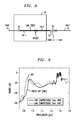
- FIG. 8 illustrates an exemplary supercontinuum generating arrangement formed in accordance with the present invention
- FIG. 9 contains plots of the continuum generated by the arrangement of FIG. 8 , as compared to prior art-generated continuum;
- FIG. 10 shows an exemplary asymmetric interferometer arrangement that may be used to measure the cross-coherence associated with the continuum generated in the arrangement of the present invention as illustrated in FIG. 8 ;
- FIG. 11 contains plots of the cross-coherence measured in the arrangement of FIG. 10 , one plot associated with the prior art SMF compression arrangement and the other associated with the all-fiber pulse compression arrangement of the present invention.
- FIG. 1 illustrates an exemplary all-fiber femtosecond pulse compressor 10 formed in accordance with the present invention.
- compressor 10 comprises a graded index (GRIN) fiber lens 12 disposed between an input fiber 14 and a section of pulse-compressing fiber 16 .
- Fibers 14 and 16 are selected such that the effective area of fiber 14 (denoted as A eff-1 ) is less than the effective area of fiber 16 (denoted as A eff-2 ) at the operating wavelength.
- a source of ‘stretched’ femtosecond pulses 18 (alternatively referred to in the art as ‘chirped’ pulses), formed in a manner well-known in the prior art, is shown in conjunction with compressor 10 in FIG. 1 .
- Source 18 is used to create a train of chirped pulses P which is thereafter coupled into input fiber 14 .
- ultrashort pulses on the order of 100 femtoseconds, for example
- Optical pulse compressor 10 of the present invention may be utilized after amplification to re-compress the pulses into their original temporal form.
- GRIN fiber lens 12 is used to provide a high quality coupling from the output of input fiber 14 into pulse-compressing fiber 16 by performing mode-matching between the two fibers.
- Pulse-compressing fiber 16 is selected to exhibit a known (positive) dispersion characteristic D at the operating wavelength, and is formed to exhibit a predetermined length L that has been found to provide the desired amount of pulse compression (e.g., to form femtosecond pulses).
- the output from pulse-compressing fiber 16 i.e., the output from optical pulse compressor 10
- the output from optical pulse compressor 10 is a train of amplified femtosecond pulses.
- the length L of fiber 16 must be selected so as to compensate for the spectral phase of the launched pulse.
- This length consideration which is based on the dispersive properties of the selected pulse-compressing fiber, is generally not a consideration in typical high power pulse amplifiers, but is considered to be an essential aspect of the arrangement of the present invention, and necessary to provide pulse compression with the desired linear properties.
- GRIN fiber lens 12 between fibers 14 and 16 eliminates the need for a bulk optic device, as was used in the prior art, to couple the pulses into the pulse-compressing fiber.
- Bulk optics are known to introduce loss, scattering, reflections and the like, all reducing the quality of the signal launched into the pulse-compressing fiber.
- the use of a fiber-based component such as GRIN fiber lens 12 significantly reduces the various coupling losses and allows for the launched pulses to achieve low levels of multi-path interference (MPI) and low nonlinearity compression in LMA fiber 16 .
- MPI multi-path interference
- an in-line fiber coupling arrangement eliminates the alignment problems associated with the use of bulk optics, since permanent alignment between the GRIN fiber lens and the pulse-compressing fiber is automatically achieved when the two are fused together (see, for example, U.S. Pat. No. 4,701,011 for a discussion of self-alignment between transmission fibers and GRIN fiber lenses).
- Another advantage of using an in-line coupling arrangement is the intrinsic isolation of the optical signal path from dust or other extrinsic contaminants, as may be found in bulk optic solutions.
- FIG. 2 contains a basic diagram illustrating the principles associated with the implementation of a graded-index fiber lens.
- FIG. 2 illustrates a Gaussian beam 100 exiting a single mode fiber 110 and thereafter passing through a parabolic-index medium 120 , which is preferably a section of multimode fiber.
- the waist position and beam size associated with Gaussian beam 100 may be found from equations well-known in the art.
- medium 120 should comprise a length L equal to ⁇ /2 g, where g is the focusing parameter of medium 120 .
- a graded-index fiber lens formed in accordance with the present invention may utilize any refractive index gradient that is capable of achieving mode-matching between the single mode fiber and the large mode area fiber.
- FIG. 4 contains graphs illustrating the improvement in compressed pulse shape that may be achieved when using the GRIN lens fiber/pulse-compressing fiber arrangement of the present invention, as compared to the prior art use of only a section of single mode fiber.
- the plot of FIG. 4( a ) shows the autocorrelation function associated with a compressed pulse train created using only a section of single mode fiber (prior art).
- the original ‘stretched’ pulses were generated by amplifying the output of a passively mode-locked fiber laser.
- the combination of normal dispersion and self-phase modulation in the single-mode, erbium-doped fiber amplifier creates pulses with a strong negative chirp.
- the output section of single mode fiber (performing the compression function) was continually reduced in length until the shortest pulse output was found.
- compression in single mode fiber is shown to include significant sidelobes in the autocorrelation function; expected as a result of the inherent nonlinearity of the single mode fiber.
- the plot of FIG. 4( b ) shows the autocorrelation function of output pulses from an all-fiber pulse compressor formed in accordance with the present invention.
- a section of large-mode area (LMA) fiber was used as the pulse-compressing fiber.
- the LMA fiber was selected to exhibit an effective area A eff-2 of 986 ⁇ m 2 at the operating wavelength of 1550 nm, with a dispersion of +21.08 ps/nm-km and a dispersion slope of 0.063 ps/nm 2 -km.
- the positive dispersion value at the operating wavelength compensates for the normal dispersion of the amplifier fiber, as well as the additional nonlinear phase due to self-phase modulation during amplification in single mode fiber.
- the generated autocorrelation function exhibits essentially no sidelobes, indicative of the elimination of nonlinearities in the all-fiber pulse compression arrangement of the present invention.
- FIG. 5 illustrates the pulse width correlation as a function of the length of the compression fiber.
- FIG. 5( a ) illustrates this correlation as a function of fiber length for a prior art pulse compressor using single mode fiber
- FIG. 5( b ) shows the same correlation as a function of length for an exemplary LMA fiber used the pulse-compressing fiber in an exemplary embodiment of the present invention.
- the correlation is seen to achieve a minimal value of about 100 fs for a length L of about 1.7 m, with an accuracy of approximately 5 cm required to achieve the minimum pulse width.
- 5 a shows a pulse centered at 1550 nm with a width on the order of 1 ps, which, if transform limited, would require a spectrum with a bandwidth (full-width at half-maximum) of approximately 2.5 nm. Chirped pulses, or transform limited pulses with shorter widths would require even more bandwidth.
- a preferred embodiment in accordance with the present invention includes the use of a second GRIN lens between the output of the pulse-compressing fiber and a transmission fiber to provide efficient mode matching between the compression arrangement and the transmission arrangement.
- FIG. 6 illustrates this embodiment of the present invention, providing a fully all-fiber pulse compression and transmission system.
- FIG. 6( a ) shows a first arrangement where a second GRIN lens 18 is disposed between the endface of pulse-compressing fiber 16 and a single mode output transmission fiber 20 .
- second GRIN lens 18 is fused between fibers 16 and 20 , since fusion provides automatic alignment between the core regions of the various fibers.
- second GRIN lens 18 is formed to have a length L′ suitable for providing mode-matching between pulse-compressing fiber 16 and SMF 20 .
- the alternative arrangement as shown in FIG. 6( b ) includes two separate sections of pulse-compressing fiber, shown as 16 - 1 and 16 - 2 , with a splice formed therebetween to couple the fibers together.
- FIG. 7 contains plots of the measured spectra for the arrangements of FIGS. 6( a ) and ( b ). The measured MPI of the arrangement of FIG. 6( a ) was ⁇ 31 dB, and the MPI for the spliced arrangement of FIG. 6( b ) was ⁇ 26 dB, showing the majority of the power is contained in the desired fundamental mode.
- MPI can potentially lead to increased noise of the compressed pulses are to be used in further nonlinear processes such as supercontinuum generation.
- HNLF highly nonlinear fiber
- the propagation of extremely short pulses (such as femtosecond pulses) through one or more sections of HNLF will generate a continuum of extremely broad bandwidth, useful in frequency metrology and other applications (such as DWDM).
- FIG. 8 illustrates an exemplary supercontinuum generation system as formed in accordance with the present invention.
- a section of highly-nonlinear fiber (HNLF) 22 is spliced to SMF 20 , using the arrangement of FIG. 6 .
- HNLF 22 may be directed fused to the endface of second GRIN fiber lens 18 .
- HNLF 22 may comprise a plurality of concatenated sections of fiber, each having different dispersion characteristics to provide a broad continuum.
- FIG. 9 contains plots of the generated continuum associated with the inventive arrangement of FIG.
- FIG. 10 illustrates an exemplary asymmetric interferometer 50 that may be used to measure the cross-coherence associated with each of the generated continuum.
- Interferometer 50 receives as an input the continuum produced by a section of HNLF, such as HNLF 22 shown in FIG. 8 .
- a beam splitter 52 is used to create two independent continua, a first continuum propagating along a first path 54 and a second continuum propagating along a second path 56 .
- Interferometer 50 is ‘asymmetric’ by forming second path 56 to be unbalanced with respect to first path 54 by a length equal to the distance between pulses in the incoming pulse train, as shown.
- the pulses then overlap within a beam combiner 58 at the output and are passed through a polarizer 60 and coupled into a section of single mode fiber 62 .
- the use of a polarizer at the output ensures polarization overlap, and the single mode fiber ensures modal overlap.
- a variable neutral density filter 64 is included along first signal path 52 and a quarter-wave plate 66 along second signal path 54 allow for power equalization between the two paths.
- An optical spectrum analyzer 68 is thereafter used to measure the fringe contrast at different wavelengths.
- FIG. 11 shows the measured cross-coherence of the continua as plotted in FIG. 9 .
- the fringe contrast will be equal to “1” (i.e., unity). Any degradation in coherence (as would be associated with the presence of noise in the generated supercontinuum) results in lowering the fringe contrast.
- FIG. 11 has plotted the fringe contrast on a dB scale to better show the difference in pulse compression between the prior art SMF pulse compression and the use of the GRIN lens/LMA combination of the present invention.
Abstract
Description
MPI=10*log(P HOM /P F),
where PHOM is the total optical power propagating in undesired higher-order modes of the compressed fiber, and PF is the optical power in the fundamental mode.
Claims (9)
Priority Applications (4)
| Application Number | Priority Date | Filing Date | Title |
|---|---|---|---|
| US12/150,692 US7844146B2 (en) | 2008-04-30 | 2008-04-30 | All-fiber module for femtosecond pulse compression and supercontinuum generation |
| EP09004466.0A EP2113798B1 (en) | 2008-04-30 | 2009-03-27 | All-fiber module for femtosecond pulse compression and supercontinuum generation |
| JP2009108832A JP5502362B2 (en) | 2008-04-30 | 2009-04-28 | All-fiber module for femtosecond pulse compression and supercontinuum generation |
| US12/911,809 US7957619B2 (en) | 2008-04-30 | 2010-10-26 | All-fiber module for femtosecond pulse compression and supercontinuum generation |
Applications Claiming Priority (1)
| Application Number | Priority Date | Filing Date | Title |
|---|---|---|---|
| US12/150,692 US7844146B2 (en) | 2008-04-30 | 2008-04-30 | All-fiber module for femtosecond pulse compression and supercontinuum generation |
Related Child Applications (1)
| Application Number | Title | Priority Date | Filing Date |
|---|---|---|---|
| US12/911,809 Division US7957619B2 (en) | 2008-04-30 | 2010-10-26 | All-fiber module for femtosecond pulse compression and supercontinuum generation |
Publications (2)
| Publication Number | Publication Date |
|---|---|
| US20090274180A1 US20090274180A1 (en) | 2009-11-05 |
| US7844146B2 true US7844146B2 (en) | 2010-11-30 |
Family
ID=40941444
Family Applications (2)
| Application Number | Title | Priority Date | Filing Date |
|---|---|---|---|
| US12/150,692 Active US7844146B2 (en) | 2008-04-30 | 2008-04-30 | All-fiber module for femtosecond pulse compression and supercontinuum generation |
| US12/911,809 Active US7957619B2 (en) | 2008-04-30 | 2010-10-26 | All-fiber module for femtosecond pulse compression and supercontinuum generation |
Family Applications After (1)
| Application Number | Title | Priority Date | Filing Date |
|---|---|---|---|
| US12/911,809 Active US7957619B2 (en) | 2008-04-30 | 2010-10-26 | All-fiber module for femtosecond pulse compression and supercontinuum generation |
Country Status (3)
| Country | Link |
|---|---|
| US (2) | US7844146B2 (en) |
| EP (1) | EP2113798B1 (en) |
| JP (1) | JP5502362B2 (en) |
Cited By (3)
| Publication number | Priority date | Publication date | Assignee | Title |
|---|---|---|---|---|
| US20100189393A1 (en) * | 2009-01-27 | 2010-07-29 | Fujikura Ltd. | Optical amplifier and resonator |
| US20120217375A1 (en) * | 2009-07-01 | 2012-08-30 | Anthony Hong Lin | Fiber lasers for producing amplified laser pulses with reduced non-linearity |
| WO2012118937A3 (en) * | 2011-03-01 | 2013-11-14 | Ofs Fitel, Inc | Method and system for ultrashort pulse fiber delivery using higher order mode fiber |
Families Citing this family (9)
| Publication number | Priority date | Publication date | Assignee | Title |
|---|---|---|---|---|
| US20100061410A1 (en) * | 2008-09-11 | 2010-03-11 | Nikolai Platonov | System and method for controlling nonlinearities in laser units |
| US8218928B2 (en) * | 2009-04-23 | 2012-07-10 | Ofs Fitel, Llc | Spatial filtering of higher order modes in multimode fibers |
| JP2011124460A (en) * | 2009-12-14 | 2011-06-23 | Fujikura Ltd | Optical fiber emission circuit and fiber laser |
| US8526772B2 (en) * | 2010-08-26 | 2013-09-03 | The Board Of Trustees Of The University Of Illinois | Compression of polarized supercontinuum pulses generated in birefringent all normal-dispersion photonic crystal fiber |
| JP2014127484A (en) | 2012-12-25 | 2014-07-07 | Sony Corp | Pulse shaping device and pulse shaping method |
| TWI474060B (en) | 2013-06-18 | 2015-02-21 | Nat Univ Tsing Hua | Supercontinuum generation system |
| JP6442432B2 (en) * | 2016-04-19 | 2018-12-19 | 株式会社フジクラ | Optical device manufacturing method, laser device manufacturing method, and laser device beam quality adjustment method |
| US10670807B2 (en) * | 2016-12-15 | 2020-06-02 | Ayar Labs, Inc. | Lens assembly for optical fiber coupling to target and associated methods |
| WO2020092712A1 (en) * | 2018-11-01 | 2020-05-07 | Ofs Fitel, Llc | Fiber-based supercontinuum light source |
Citations (33)
| Publication number | Priority date | Publication date | Assignee | Title |
|---|---|---|---|---|
| US4560247A (en) * | 1983-07-01 | 1985-12-24 | Quartz Et Silice | Large bandwidth optical fibers |
| US4701011A (en) * | 1985-01-15 | 1987-10-20 | American Telephone And Telegraph Company, At&T Bell Laboratories | Multimode fiber-lens optical coupler |
| GB2260048A (en) | 1991-09-26 | 1993-03-31 | American Telephone & Telegraph | Apparatus for compensating chromatic dispersion in optical fibers |
| US5712937A (en) * | 1994-12-01 | 1998-01-27 | Asawa; Charles K. | Optical waveguide including singlemode waveguide channels coupled to a multimode fiber |
| US6081543A (en) | 1998-05-14 | 2000-06-27 | The Regents Of The University Of Michigan | Stretcher-compressor assembly having a single grating |
| US6249630B1 (en) | 1996-12-13 | 2001-06-19 | Imra America, Inc. | Apparatus and method for delivery of dispersion-compensated ultrashort optical pulses with high peak power |
| US20020012498A1 (en) | 1998-03-26 | 2002-01-31 | Yochay Danziger | Transverse spatial mode transformer for optical communication |
| US20020150333A1 (en) | 2001-02-17 | 2002-10-17 | Reed William Alfred | Fiber devices using grin fiber lenses |
| US6542665B2 (en) | 2001-02-17 | 2003-04-01 | Lucent Technologies Inc. | GRIN fiber lenses |
| US6549702B2 (en) * | 1999-02-19 | 2003-04-15 | The Regents Of The University Of Michigan | Method and system for generating a broadband spectral continuum, method of making the system and pulse-generating system utilizing same |
| US20030156605A1 (en) | 2002-02-18 | 2003-08-21 | Richardson David J. | Pulsed light sources |
| US6650466B1 (en) | 1999-08-27 | 2003-11-18 | Frank Wise | High-energy pulse compression using phase shifts produced by the cascade quadriatic nonlinearity |
| US20040042714A1 (en) | 2002-09-04 | 2004-03-04 | Siddharth Ramachandran | Tunable mode-converters using few mode fibers |
| US6775447B2 (en) * | 2002-09-20 | 2004-08-10 | Fitel Usa Corp. | All fiber low noise supercontinuum source |
| WO2005041367A1 (en) | 2003-10-24 | 2005-05-06 | Nkt Research & Innovation A/S | An optical system for providing short laser-pulses |
| US6970624B2 (en) | 2003-06-13 | 2005-11-29 | Furukawa Electric North America | Cladding pumped optical fiber gain devices |
| US20050265653A1 (en) | 2004-05-25 | 2005-12-01 | Avanex Corporation | Apparatus, system and method for an adiabatic coupler for multi-mode fiber-optic transmission systems |
| US6990270B2 (en) * | 2004-02-11 | 2006-01-24 | Fitel U.S.A. Corp. | Fiber amplifier for generating femtosecond pulses in single mode fiber |
| WO2006027298A1 (en) | 2004-09-08 | 2006-03-16 | Alcatel Lucent | A mode converter |
| US7013678B2 (en) | 2002-09-19 | 2006-03-21 | Fitel Usa Corp | Method of fabricating graded-index optical fiber lenses |
| US7116874B2 (en) | 2004-02-20 | 2006-10-03 | Fitel Usa Corp. | Enhanced supercontinuum generation in highly nonlinear fibers using strong bragg gratings |
| US20060227816A1 (en) | 2005-04-06 | 2006-10-12 | Jian Liu | All fiber based short pulse amplification at one micron |
| US20060233554A1 (en) | 2005-04-14 | 2006-10-19 | Siddharth Ramachandran | Optical fiber systems for delivering short high power pulses |
| EP1764885A2 (en) | 2005-09-20 | 2007-03-21 | Furukawa Electric North America Inc. (a Delaware Corporation) | Short pulse lasers using large mode area fibers and higher order modes |
| US20070177641A1 (en) | 2005-05-23 | 2007-08-02 | Polaronyx, Inc. | Nonlinear polarization pulse shaping model locked fiber laser at one micron with photonic crystal (PC), photonic bandgap (PBG), or higher order mode (HOM) fiber |
| US20070177640A1 (en) | 2006-02-02 | 2007-08-02 | Polaronyx, Inc. | Practical approach for one mJ femtosecond fiber laser |
| US20070206647A1 (en) | 2006-03-06 | 2007-09-06 | Polaronyx, Inc. | Dispersion managed fiber stretcher for high-energy short pulse femotosecond fiber laser system |
| US7340138B1 (en) * | 2007-01-25 | 2008-03-04 | Furukawa Electric North America, Inc. | Optical fiber devices and methods for interconnecting dissimilar fibers |
| US7340135B2 (en) * | 2005-03-31 | 2008-03-04 | Sumitomo Electric Industries, Ltd. | Light source apparatus |
| US20080180787A1 (en) * | 2007-01-26 | 2008-07-31 | Digiovanni David John | High power optical apparatus employing large-mode-area, multimode, gain-producing optical fibers |
| US7426328B2 (en) * | 2002-08-28 | 2008-09-16 | Phosistor Technologies, Inc. | Varying refractive index optical medium using at least two materials with thicknesses less than a wavelength |
| US7430224B2 (en) * | 2005-08-29 | 2008-09-30 | Polaronyx, Inc. | Automatic dispersion compensation in amplification for short pulse fiber laser system |
| US7508853B2 (en) * | 2004-12-07 | 2009-03-24 | Imra, America, Inc. | Yb: and Nd: mode-locked oscillators and fiber systems incorporated in solid-state short pulse laser systems |
Family Cites Families (3)
| Publication number | Priority date | Publication date | Assignee | Title |
|---|---|---|---|---|
| US6526208B1 (en) * | 2000-11-27 | 2003-02-25 | Nortel Networks Limited | Dispersion managed fiber optic cable and system |
| EP1260841B1 (en) * | 2001-05-19 | 2007-07-11 | Lucent Technologies Inc. | GRIN fiber lenses |
| JP4346328B2 (en) * | 2003-03-07 | 2009-10-21 | 古河電気工業株式会社 | Optical transmission line |
-
2008
- 2008-04-30 US US12/150,692 patent/US7844146B2/en active Active
-
2009
- 2009-03-27 EP EP09004466.0A patent/EP2113798B1/en active Active
- 2009-04-28 JP JP2009108832A patent/JP5502362B2/en active Active
-
2010
- 2010-10-26 US US12/911,809 patent/US7957619B2/en active Active
Patent Citations (35)
| Publication number | Priority date | Publication date | Assignee | Title |
|---|---|---|---|---|
| US4560247A (en) * | 1983-07-01 | 1985-12-24 | Quartz Et Silice | Large bandwidth optical fibers |
| US4701011A (en) * | 1985-01-15 | 1987-10-20 | American Telephone And Telegraph Company, At&T Bell Laboratories | Multimode fiber-lens optical coupler |
| GB2260048A (en) | 1991-09-26 | 1993-03-31 | American Telephone & Telegraph | Apparatus for compensating chromatic dispersion in optical fibers |
| US5712937A (en) * | 1994-12-01 | 1998-01-27 | Asawa; Charles K. | Optical waveguide including singlemode waveguide channels coupled to a multimode fiber |
| US6249630B1 (en) | 1996-12-13 | 2001-06-19 | Imra America, Inc. | Apparatus and method for delivery of dispersion-compensated ultrashort optical pulses with high peak power |
| US20020012498A1 (en) | 1998-03-26 | 2002-01-31 | Yochay Danziger | Transverse spatial mode transformer for optical communication |
| US6081543A (en) | 1998-05-14 | 2000-06-27 | The Regents Of The University Of Michigan | Stretcher-compressor assembly having a single grating |
| US6549702B2 (en) * | 1999-02-19 | 2003-04-15 | The Regents Of The University Of Michigan | Method and system for generating a broadband spectral continuum, method of making the system and pulse-generating system utilizing same |
| US6650466B1 (en) | 1999-08-27 | 2003-11-18 | Frank Wise | High-energy pulse compression using phase shifts produced by the cascade quadriatic nonlinearity |
| US20020150333A1 (en) | 2001-02-17 | 2002-10-17 | Reed William Alfred | Fiber devices using grin fiber lenses |
| US6542665B2 (en) | 2001-02-17 | 2003-04-01 | Lucent Technologies Inc. | GRIN fiber lenses |
| US20030156605A1 (en) | 2002-02-18 | 2003-08-21 | Richardson David J. | Pulsed light sources |
| US7426328B2 (en) * | 2002-08-28 | 2008-09-16 | Phosistor Technologies, Inc. | Varying refractive index optical medium using at least two materials with thicknesses less than a wavelength |
| US20040042714A1 (en) | 2002-09-04 | 2004-03-04 | Siddharth Ramachandran | Tunable mode-converters using few mode fibers |
| US7013678B2 (en) | 2002-09-19 | 2006-03-21 | Fitel Usa Corp | Method of fabricating graded-index optical fiber lenses |
| US6775447B2 (en) * | 2002-09-20 | 2004-08-10 | Fitel Usa Corp. | All fiber low noise supercontinuum source |
| US6970624B2 (en) | 2003-06-13 | 2005-11-29 | Furukawa Electric North America | Cladding pumped optical fiber gain devices |
| WO2005041367A1 (en) | 2003-10-24 | 2005-05-06 | Nkt Research & Innovation A/S | An optical system for providing short laser-pulses |
| US6990270B2 (en) * | 2004-02-11 | 2006-01-24 | Fitel U.S.A. Corp. | Fiber amplifier for generating femtosecond pulses in single mode fiber |
| US7171089B2 (en) | 2004-02-20 | 2007-01-30 | Fitel Usa Corp. | Enhanced supercontinuum generation in highly nonlinear fibers using post-fabrication processing |
| US7116874B2 (en) | 2004-02-20 | 2006-10-03 | Fitel Usa Corp. | Enhanced supercontinuum generation in highly nonlinear fibers using strong bragg gratings |
| US20050265653A1 (en) | 2004-05-25 | 2005-12-01 | Avanex Corporation | Apparatus, system and method for an adiabatic coupler for multi-mode fiber-optic transmission systems |
| WO2006027298A1 (en) | 2004-09-08 | 2006-03-16 | Alcatel Lucent | A mode converter |
| US7508853B2 (en) * | 2004-12-07 | 2009-03-24 | Imra, America, Inc. | Yb: and Nd: mode-locked oscillators and fiber systems incorporated in solid-state short pulse laser systems |
| US7340135B2 (en) * | 2005-03-31 | 2008-03-04 | Sumitomo Electric Industries, Ltd. | Light source apparatus |
| US20060227816A1 (en) | 2005-04-06 | 2006-10-12 | Jian Liu | All fiber based short pulse amplification at one micron |
| US20060233554A1 (en) | 2005-04-14 | 2006-10-19 | Siddharth Ramachandran | Optical fiber systems for delivering short high power pulses |
| US20070177641A1 (en) | 2005-05-23 | 2007-08-02 | Polaronyx, Inc. | Nonlinear polarization pulse shaping model locked fiber laser at one micron with photonic crystal (PC), photonic bandgap (PBG), or higher order mode (HOM) fiber |
| US7430224B2 (en) * | 2005-08-29 | 2008-09-30 | Polaronyx, Inc. | Automatic dispersion compensation in amplification for short pulse fiber laser system |
| EP1764885A2 (en) | 2005-09-20 | 2007-03-21 | Furukawa Electric North America Inc. (a Delaware Corporation) | Short pulse lasers using large mode area fibers and higher order modes |
| US7228029B1 (en) * | 2005-09-20 | 2007-06-05 | Furukawa Electric North America Inc. | Short pulse lasers using large mode area fibers and higher order modes |
| US20070177640A1 (en) | 2006-02-02 | 2007-08-02 | Polaronyx, Inc. | Practical approach for one mJ femtosecond fiber laser |
| US20070206647A1 (en) | 2006-03-06 | 2007-09-06 | Polaronyx, Inc. | Dispersion managed fiber stretcher for high-energy short pulse femotosecond fiber laser system |
| US7340138B1 (en) * | 2007-01-25 | 2008-03-04 | Furukawa Electric North America, Inc. | Optical fiber devices and methods for interconnecting dissimilar fibers |
| US20080180787A1 (en) * | 2007-01-26 | 2008-07-31 | Digiovanni David John | High power optical apparatus employing large-mode-area, multimode, gain-producing optical fibers |
Non-Patent Citations (8)
| Title |
|---|
| Chanclou et al. "Design and Performance of Expanded Mode Fiber using Microoptics", Journal of Lightwave Technology vol. 29, No. 5, May 2002. |
| Chanclou et al., "Expanded Single-Mode Fiber Using Graded Index Multimode Fiber", 2004 Society of Photo-Optical Intrumentation Engineers, Jul. 2004, pp. 1634-1642. |
| Emkay et al., "Analysis and Evaluation of Graded-Index Fiber Lenses", Journal of Lightwave Technology, vol. LT-5, No. 9 Sep. 1987, pp. 1156-1164. |
| Galvanauskas, "Mode-Scalable Fiber-Based Chirped Pulse Amplification Systems", IEEE Journal on Selected Topics In Quantum Electronics, Jul./Aug. 2001. |
| Itoh, et al, "Femtosecond Pulse Delivery Through Long Multimode Fiber Using Adaptive Pulse Synthesis", Japanese Journal of Applied Physics, Part 1 Japan Soc. Appl. Phys Japan vol. 45, No. 7, Jul. 2006, pp. 5761-5763. |
| Nicholson et al. "Cross-Coherence Measurements of Supercontinua Generated in Highly-Nonlinear, Dispersion Shifted Fiber at 1550 nm", Optics Express, Feb. 23, 2004, vol. 12, No. 4. |
| Ramachandran et al, "Robust, Single-Moded, Broadband Transmission and Pulse Compression in a Record Aeff (2100 Micrometre 2) Higher-Order-Mode Fiber" Proceedings of the European Conference on Optical Communication, vol. 6, Jan. 1, 2005, pp. 37-38. |
| Shiraishi et al.,"Spotsize Contraction in Standard Single-Mode Fibers by Use of a GI-Fiber Tip with a Hight Focusing Parameter" IEEE Photonics Tech. Letters, vol. 10, Dec. 1998. |
Cited By (6)
| Publication number | Priority date | Publication date | Assignee | Title |
|---|---|---|---|---|
| US20100189393A1 (en) * | 2009-01-27 | 2010-07-29 | Fujikura Ltd. | Optical amplifier and resonator |
| US8509580B2 (en) * | 2009-01-27 | 2013-08-13 | Fujikura Ltd. | Optical amplifier and resonator |
| US8781274B2 (en) | 2009-01-27 | 2014-07-15 | Fujikura Ltd. | Optical amplifier and resonator |
| US20120217375A1 (en) * | 2009-07-01 | 2012-08-30 | Anthony Hong Lin | Fiber lasers for producing amplified laser pulses with reduced non-linearity |
| US8830567B2 (en) * | 2009-07-01 | 2014-09-09 | Calmar Optcom, Inc. | Fiber lasers for producing amplified laser pulses with reduced non-linearity |
| WO2012118937A3 (en) * | 2011-03-01 | 2013-11-14 | Ofs Fitel, Inc | Method and system for ultrashort pulse fiber delivery using higher order mode fiber |
Also Published As
| Publication number | Publication date |
|---|---|
| US20110058769A1 (en) | 2011-03-10 |
| JP2009271528A (en) | 2009-11-19 |
| US20090274180A1 (en) | 2009-11-05 |
| US7957619B2 (en) | 2011-06-07 |
| JP5502362B2 (en) | 2014-05-28 |
| EP2113798A1 (en) | 2009-11-04 |
| EP2113798B1 (en) | 2014-06-25 |
Similar Documents
| Publication | Publication Date | Title |
|---|---|---|
| US7844146B2 (en) | All-fiber module for femtosecond pulse compression and supercontinuum generation | |
| US6249630B1 (en) | Apparatus and method for delivery of dispersion-compensated ultrashort optical pulses with high peak power | |
| US5862287A (en) | Apparatus and method for delivery of dispersion compensated ultrashort optical pulses with high peak power | |
| US20070160092A1 (en) | Broad-band light source | |
| Poole et al. | Optical fiber-based dispersion compensation using higher order modes near cutoff | |
| JP4769188B2 (en) | High power fiber chirped pulse amplification system using communication-type components | |
| EP2682813B1 (en) | Optical amplifier, optical amplifying system, wavelength converter, optical amplification method, and optical communication system | |
| US7477666B2 (en) | All fiber based short pulse amplification at one micron | |
| US7340135B2 (en) | Light source apparatus | |
| US20100061410A1 (en) | System and method for controlling nonlinearities in laser units | |
| US20070053641A1 (en) | Optical fiber and optical device using the same | |
| WO2007105692A1 (en) | Optical fiber and broadband light source | |
| Kobayashi et al. | 10-MHz, Yb-fiber chirped-pulse amplifier system with large-scale transmission gratings | |
| Eslami et al. | Two octave supercontinuum generation in a non-silica graded-index multimode fiber | |
| US20090323735A1 (en) | Pulse stretching optical fiber and related systems and methods | |
| CN106159664A (en) | All-fiber high-energy ultra-short pulse laser system | |
| Gauthier et al. | Femtosecond tunable solitons up to 4.8 µm using soliton self-frequency shift in an InF3 fiber | |
| EP1855155A1 (en) | Light source device | |
| Thulasi et al. | Dual wavelength generation and wavelength tunability in Yb-doped mode-locked laser using few-mode fiber as a saturable absorber | |
| Mueller et al. | 3.5 kW coherently combined ultrafast fiber laser | |
| LU101629B1 (en) | A method and system for generation of optical pulses of light | |
| Nicholson et al. | Characterizing the modes of a core-pumped, large-mode area Er fiber using spatially and spectrally resolved imaging | |
| Development of coherent mid-infrared source using chalcogenide photonic crystal fibers | ||
| Roy et al. | Gain Flattening of Erbium-Doped Fiber Amplifier Using an In-Line MSM Fiber Structure | |
| Cross | Steps towards a tunable vacuum ultraviolet light source for TR-ARPES |
Legal Events
| Date | Code | Title | Description |
|---|---|---|---|
| AS | Assignment |
Owner name: FURUKAWA ELECTRIC NORTH AMERICA, INC., GEORGIA Free format text: ASSIGNMENT OF ASSIGNORS INTEREST;ASSIGNORS:NICHOLSON, JEFFREY W.;YABLON, ANDREW D.;REEL/FRAME:020945/0373 Effective date: 20080418 |
|
| AS | Assignment |
Owner name: OFS FITEL, LLC, GEORGIA Free format text: ASSIGNMENT OF ASSIGNORS INTEREST;ASSIGNOR:FURUKAWA ELECTRIC NORTH AMERICA INC.;REEL/FRAME:025103/0341 Effective date: 20081222 |
|
| FEPP | Fee payment procedure |
Free format text: PAYOR NUMBER ASSIGNED (ORIGINAL EVENT CODE: ASPN); ENTITY STATUS OF PATENT OWNER: LARGE ENTITY |
|
| STCF | Information on status: patent grant |
Free format text: PATENTED CASE |
|
| AS | Assignment |
Owner name: FURUKAWA ELECTRIC CO., LTD., JAPAN Free format text: ASSIGNMENT OF ASSIGNORS INTEREST;ASSIGNOR:OFS FITEL, LLC;REEL/FRAME:026074/0953 Effective date: 20110228 |
|
| FPAY | Fee payment |
Year of fee payment: 4 |
|
| MAFP | Maintenance fee payment |
Free format text: PAYMENT OF MAINTENANCE FEE, 8TH YEAR, LARGE ENTITY (ORIGINAL EVENT CODE: M1552) Year of fee payment: 8 |
|
| MAFP | Maintenance fee payment |
Free format text: PAYMENT OF MAINTENANCE FEE, 12TH YEAR, LARGE ENTITY (ORIGINAL EVENT CODE: M1553); ENTITY STATUS OF PATENT OWNER: LARGE ENTITY Year of fee payment: 12 |