US7845936B2 - Sealing arrangement for an edge gated nozzle in an injection molding system - Google Patents
Sealing arrangement for an edge gated nozzle in an injection molding system Download PDFInfo
- Publication number
- US7845936B2 US7845936B2 US12/356,559 US35655909A US7845936B2 US 7845936 B2 US7845936 B2 US 7845936B2 US 35655909 A US35655909 A US 35655909A US 7845936 B2 US7845936 B2 US 7845936B2
- Authority
- US
- United States
- Prior art keywords
- nozzle
- injection molding
- molding system
- spacer element
- bore
- Prior art date
- Legal status (The legal status is an assumption and is not a legal conclusion. Google has not performed a legal analysis and makes no representation as to the accuracy of the status listed.)
- Active, expires
Links
- 238000001746 injection moulding Methods 0.000 title claims abstract description 58
- 238000007789 sealing Methods 0.000 title abstract description 14
- 125000006850 spacer group Chemical group 0.000 claims abstract description 54
- 238000011144 upstream manufacturing Methods 0.000 claims abstract description 29
- 238000004891 communication Methods 0.000 claims abstract description 8
- 239000012530 fluid Substances 0.000 claims abstract description 8
- 239000000155 melt Substances 0.000 claims description 21
- 239000012212 insulator Substances 0.000 claims description 9
- 238000012546 transfer Methods 0.000 claims description 8
- 239000000463 material Substances 0.000 claims description 7
- 238000010438 heat treatment Methods 0.000 claims description 4
- 238000013461 design Methods 0.000 description 3
- RYGMFSIKBFXOCR-UHFFFAOYSA-N Copper Chemical compound [Cu] RYGMFSIKBFXOCR-UHFFFAOYSA-N 0.000 description 1
- 229910000881 Cu alloy Inorganic materials 0.000 description 1
- 229910001315 Tool steel Inorganic materials 0.000 description 1
- 238000005219 brazing Methods 0.000 description 1
- 230000000295 complement effect Effects 0.000 description 1
- 238000001816 cooling Methods 0.000 description 1
- 229910052802 copper Inorganic materials 0.000 description 1
- 239000010949 copper Substances 0.000 description 1
- 238000012423 maintenance Methods 0.000 description 1
- 238000012986 modification Methods 0.000 description 1
- 230000004048 modification Effects 0.000 description 1
- 238000012545 processing Methods 0.000 description 1
- 230000003252 repetitive effect Effects 0.000 description 1
- 239000000243 solution Substances 0.000 description 1
- 230000000087 stabilizing effect Effects 0.000 description 1
Images


Classifications
-
- B—PERFORMING OPERATIONS; TRANSPORTING
- B29—WORKING OF PLASTICS; WORKING OF SUBSTANCES IN A PLASTIC STATE IN GENERAL
- B29C—SHAPING OR JOINING OF PLASTICS; SHAPING OF MATERIAL IN A PLASTIC STATE, NOT OTHERWISE PROVIDED FOR; AFTER-TREATMENT OF THE SHAPED PRODUCTS, e.g. REPAIRING
- B29C45/00—Injection moulding, i.e. forcing the required volume of moulding material through a nozzle into a closed mould; Apparatus therefor
- B29C45/17—Component parts, details or accessories; Auxiliary operations
- B29C45/26—Moulds
- B29C45/27—Sprue channels ; Runner channels or runner nozzles
- B29C2045/277—Spacer means or pressure pads between manifold and mould plates
-
- B—PERFORMING OPERATIONS; TRANSPORTING
- B29—WORKING OF PLASTICS; WORKING OF SUBSTANCES IN A PLASTIC STATE IN GENERAL
- B29C—SHAPING OR JOINING OF PLASTICS; SHAPING OF MATERIAL IN A PLASTIC STATE, NOT OTHERWISE PROVIDED FOR; AFTER-TREATMENT OF THE SHAPED PRODUCTS, e.g. REPAIRING
- B29C45/00—Injection moulding, i.e. forcing the required volume of moulding material through a nozzle into a closed mould; Apparatus therefor
- B29C45/17—Component parts, details or accessories; Auxiliary operations
- B29C45/26—Moulds
- B29C45/27—Sprue channels ; Runner channels or runner nozzles
- B29C2045/2796—Axially movable nozzles or nozzle tips
- B29C2045/2798—Axially movable nozzles or nozzle tips for compensating thermal expansion
-
- B—PERFORMING OPERATIONS; TRANSPORTING
- B29—WORKING OF PLASTICS; WORKING OF SUBSTANCES IN A PLASTIC STATE IN GENERAL
- B29C—SHAPING OR JOINING OF PLASTICS; SHAPING OF MATERIAL IN A PLASTIC STATE, NOT OTHERWISE PROVIDED FOR; AFTER-TREATMENT OF THE SHAPED PRODUCTS, e.g. REPAIRING
- B29C45/00—Injection moulding, i.e. forcing the required volume of moulding material through a nozzle into a closed mould; Apparatus therefor
- B29C45/17—Component parts, details or accessories; Auxiliary operations
- B29C45/26—Moulds
- B29C45/27—Sprue channels ; Runner channels or runner nozzles
- B29C45/2735—Sprue channels ; Runner channels or runner nozzles for non-coaxial gates, e.g. for edge gates
Definitions
- the invention relates generally to an injection molding system and, in particular, to a sealing arrangement between a hot runner manifold and nozzle of the system to accommodate thermal expansion.
- a multi-cavity injection molding apparatus having a hot runner manifold for delivering a melt stream of moldable material to a plurality of hot runner nozzles.
- Heat expansion can cause the manifold to warp.
- the distance between the lower surface of the manifold and each of a plurality of mold cavities varies and thus each nozzle is subjected to unique operating conditions depending on the nozzle's location relative to the manifold.
- the thermal expansion results in a variable sealing force being applied to both the interface between the nozzle and manifold and the nozzle and mold gate.
- an uneven sealing condition may allow the pressurized melt to leak at the interface between the manifold and each nozzle and/or in the mold gate area around the nozzle seals. If the nozzles are threaded into the manifold, an uneven sealing condition may still allow the pressurized melt to leak in the mold gate area.
- nozzle designs rely on thermal expansion of the nozzle to provide sealing at the mold gate and at the nozzle/manifold interface, which can be aided by the use of one or more pressure disks between a back plate and an upstream surface of the manifold.
- edge gated nozzles which are nozzles having a number of radially extending or horizontal tips
- the radially extending tips are generally axially fixed in position to align with the mold gate and therefore the conventional edge gated nozzle may be prevented from thermal expansion in a longitudinal direction.
- leakage may occur between the tip and mold gate or the tip and nozzle due to the large amount of force acting on the tips under operating conditions.
- Leakage may also occur at the nozzle and manifold interface because in a conventional edge gated system that does not allow for thermal expansion of the nozzle, pressure disks that usually provide sealing support at this interface are ineffective, as such pressure disks do not work without the changes in force experienced by thermal expansion of the nozzle.
- Embodiments hereof are directed to an injection molding apparatus having a sealing arrangement between a hot runner manifold and edge-gated nozzle that accommodates thermal expansion during operation.
- a spacer element is axially fixed in position between the manifold and a mold plate, wherein the nozzle sits within an opening of the mold plate.
- the nozzle includes a reduced diameter spigot portion on an upstream end that is in a telescopic/slidable relationship with a bore of the spacer element.
- the nozzle includes radially extended nozzle tips axially fixed in position at a downstream end of the nozzle that are in fluid communication with respective mold gates and corresponding mold cavities.
- a gap G exists between a shoulder of the nozzle proximate the spigot portion and a corresponding surface of the spacer element bore.
- FIG. 1 is a cross-sectional view of an edge-gated injection molding apparatus according to an embodiment of the present invention.
- FIG. 2 is an enlarged view of a portion of the injection molding apparatus of FIG. 1 .
- FIG. 3 is the injection molding apparatus of FIG. 2 modified in accordance with another embodiment of the present invention.
- FIG. 4 is the injection molding apparatus of FIG. 2 modified in accordance with another embodiment of the present invention.
- FIG. 5 is the injection molding apparatus of FIG. 2 modified in accordance with another embodiment of the present invention.
- FIG. 6 is the injection molding apparatus of FIG. 2 modified in accordance with another embodiment of the present invention.
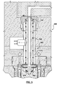
- FIG. 7 is the injection molding apparatus of FIG. 2 modified in accordance with another embodiment of the present invention.
- FIG. 7A is an exploded view of an upstream portion of the nozzle and spacer element of FIG. 7 .
- FIG. 8 is the injection molding apparatus of FIG. 7 further modified in accordance with another embodiment of the present invention.
- FIG. 8A is the injection molding apparatus of FIG. 8 further modified in accordance with another embodiment of the present invention.
- Directional terms are used in the following description with respect to a position or direction relative to a stationary platen of an injection molding machine. “Forward” or “front” are a position distant from or in a direction away from the stationary platen. “Rearward” and “back” are a position near or in a direction toward the stationary platen. In addition, “upstream” and “downstream” refer to the direction of flow of a melt stream of moldable material.
- FIG. 1 is a cross-sectional view of a multi-cavity edge-gated injection molding apparatus 100 according to an embodiment of the present invention.
- edge-gated injection molding apparatus 100 includes several nozzles 102 , two of which are shown in FIG. 1 , that are coupled to a hot runner manifold 106 to receive a melt stream of moldable material therefrom.
- Each nozzle 102 is mounted in an opening 109 in mold plates 108 , 110 and includes a nozzle melt channel 103 for receiving the melt stream from a manifold melt channel 107 and delivering the melt stream to mold cavities 101 via mold gates 111 .
- Nozzles 102 include nozzle heaters 126 that are monitored and controlled by independent thermocouples (not shown), and manifold 106 includes a manifold heater 130 .
- Nozzle heaters 126 and manifold heater 130 are provided to maintain the melt stream of moldable material within melt channels 103 , 107 , respectively, at a proper processing temperature.
- Mold cavities 101 are formed between respective cavity inserts 154 , 154 ′ and mold cores 156 .
- Cavity insert 154 is disposed within mold plate 108 ′ and includes seals 150 and cooling channels 152 therebetween.
- Cavity insert 154 ′ is disposed within mold plate 110 .
- Each mold core 156 is held in place by a mold insert 158 .
- Mold cavities 101 are radially spaced around nozzle 102 and a nozzle tip 116 that is coupled to a downstream end of nozzle 102 is aligned with a respective mold gate 111 . As such, the location of nozzle tips 116 is generally fixed relative to mold plates 108 , 110 and 108 ′.
- manifold 106 is spaced from a back plate 151 and mold plate 108 by an insulative air space that is maintained therebetween by pressure disks 155 and a locating ring 157 .
- Pressure disks suitable for use in embodiments hereof are disclosed in U.S. Pat. No. 5,125,827 to Gellert, which is incorporated by reference herein in its entirety.
- a sprue bushing 153 is fixed to back plate 151 and includes a melt inlet 159 that permits a sliding/telescopic connection with manifold 106 . This connection accommodates some thermal expansion of manifold 106 and nozzle 102 in an axial direction.
- nozzle 102 includes a spigot portion 112 that is in a sliding/telescopic arrangement with a spacer element 104 that is axially fixed in position between manifold 106 and mold plate 108 , as described in more detail below.
- such an arrangement between manifold 106 and nozzles 102 accommodates a load condition that may otherwise cause misalignment of nozzle tips 116 with their respective mold gates 111 and/or excessive wear of nozzle tips 116 and thereby prevents leakage and reduces repair and maintenance of these components.
- FIG. 2 is an enlarged view of a portion of injection molding apparatus 100 of FIG. 1 .
- Nozzle 102 includes a nozzle body portion 214 that is defined between nozzle spigot portion 112 and a downstream end 205 of nozzle 102 with nozzle melt channel 103 being centrally disposed through both spigot portion 112 and nozzle body portion 214 .
- Nozzle tips 116 radially extend from downstream end 205 of nozzle body portion 214 .
- Each nozzle tip 116 includes a nozzle tip component 225 having a melt channel 229 for delivering the melt stream from nozzle melt channel 103 to mold cavity 101 via mold gate 111 and a transfer seal component 227 that retains nozzle tip component 225 to nozzle body portion 214 .
- FIG. 1 is an enlarged view of a portion of injection molding apparatus 100 of FIG. 1 .
- Nozzle 102 includes a nozzle body portion 214 that is defined between nozzle spigot portion 112 and a downstream end 205 of nozzle 102 with
- each transfer seal component 227 includes threads for engaging corresponding threads within a side bore 231 of nozzle body portion 214 .
- Each transfer seal component 227 is in contact with an area of mold cavity inserts 154 , 154 ′ that surrounds mold gate 111 to align nozzle tip component 225 with mold gate 111 and seal against melt leakage around mold gate 111 .
- Extending from downstream end 105 of nozzle body portion 214 is a central locator post 226 that fits within a corresponding recess 228 in cavity insert 154 for aligning nozzle tips 116 with mold gates 111 .
- Central locator post 226 assures a proper height of nozzle tips 116 with respect to mold gates 111 to permit proper centering thereof.
- An insulative annular component 233 surrounding central locator post 226 is positioned between downstream end 205 of nozzle body portion 214 and cavity insert 154 . It would be understood by one of skill in the art of mold design that mold cavity 101 could be formed by one or more mold cavity plates rather than by mold cavity inserts 154 , 154 ′ without departing from the scope of the present invention. In such an alternate design, a transfer seal component would contact an area of the mold cavity plates around the mold gate and be aligned therewith in a manner as previously discussed.
- nozzle tips 116 are shown extending directly from, or in-line with, the radially extended portion of nozzle melt channel 103 and normal to the side surface of nozzle body portion 214 , it should be understood that nozzle tips 116 may extend at any angle from the radially extended portion of nozzle melt channel 103 and/or the side or forward surface of nozzle body portion 214 without departing from the scope of the present invention.
- An exemplary two-piece nozzle seal arrangement that may be used in embodiments of the present invention is disclosed in U.S. Pat. No. 5,299,928 to Gellert, which is incorporated by reference herein in its entirety.
- Spacer element 104 has an upstream surface 215 that contacts a downstream surface 218 of manifold 106 and has a downstream end 217 disposed within an annular seat 219 in mold plate 108 to be axially fixed in position. Downstream end 217 is the only portion of spacer element 104 that makes contact with mold plate 108 to minimize heat loss from manifold 106 and nozzle 102 .
- An inner surface of spacer element 104 defines a stepped bore 220 having a first bore portion 222 of a first diameter ID 1 that slidably receives an upstream end of nozzle body portion 214 of an outer diameter OD 1 .
- Spacer element stepped bore 220 also defines a second bore portion 224 of a second diameter ID 2 , which is less than ID 1 , that slidably receives spigot portion 112 of an outer diameter OD 2 , which is less than OD 1 .
- a planar surface 223 is defined between first and second bore portions 222 , 224 and a corresponding shoulder 213 is defined between spigot portion 112 and nozzle body portion 214 .
- a gap G that is sized to accommodate thermal expansion of injection molding system 100 exists between nozzle shoulder 213 and planar surface 223 of spacer element bore 220 .
- an upstream end 271 of spigot portion 112 is spaced from downstream surface 218 of manifold 106 in order to allow for sliding movement of spigot portion 112 within second bore portion 224 as the system is brought to an operating temperature, as discussed below.
- spigot portion 112 and the upstream end of nozzle body portion 214 may slide within spacer element first and second bore portions 222 , 224 , respectively thereby moving upstream end 271 of spigot portion 112 closer to or in contact with downstream surface 218 of manifold 106 .
- FIGS. 3-8 are similar to injection molding apparatus 100 of FIG. 1 but include various modifications in accordance with further embodiments of the present invention. Features that appear in FIGS. 3-8 that are the same as those previously described with reference to the embodiment of FIGS. 1 and 2 will not be further described below.
- injection molding apparatus 300 includes a biasing member 330 positioned within gap “G” between nozzle shoulder 213 and spacer element annular seat 223 .
- Biasing member 330 helps to maintain sealing contact between upstream surface 215 of spacer element 104 and downstream surface 218 of manifold 106 before and during operation.
- Biasing member 330 may be a spring as shown in FIGS. 3 , 5 , 7 and 8 or in other embodiments may be a bevel washer or a metallic o-ring as shown in FIG. 8B .
- injection molding apparatus 400 includes a nozzle 402 having a nozzle body portion 414 without a central locator post extending from a distal end 405 thereof.
- nozzle 402 does not make contact with mold plates 108 , 110 or cavity inserts 154 , 154 ′ except through nozzle tips 116 and spacer element 104 thereby minimizing heat loss therefrom.
- Axial thermal expansion of nozzle 402 is restricted in a direction of mold cavities 101 by engagement of transfer seals 227 with mold cavity inserts 154 , 154 ′.
- nozzle heaters 126 have heating elements that are positioned in a groove within nozzle body portions 214 , 414 that extends from an upstream end of nozzle body portion 214 to nozzle tips 116 .
- nozzle 502 has a nozzle heater 526 that includes a heating element segment 535 in a groove within downstream end 505 of nozzle body portion 514 .
- nozzle 602 includes a groove within nozzle body portion 614 that extends from an upstream end of nozzle body portion 614 to downstream of nozzle tips 616 .
- nozzle heater 626 has a heating element segment that is positioned in the groove downstream of nozzle tips 616 .
- nozzle 602 has a nozzle body portion 614 without a central locator post extending from a distal end 605 thereof.
- each of nozzle tips 616 is a single component that is directly coupled to a respective side of nozzle body portion 614 , either by threads or brazing, and does not include a transfer seal piece.
- Nozzle tips 616 contact the mold component proximate mold gates 111 to assure alignment of nozzle tips 616 with mold gates 111 .
- a locator sleeve 640 surrounds nozzle body portion 614 upstream of nozzle tips 616 .
- Locator sleeve 640 has a circumferential projection 641 for engaging annular seat 646 in mold cavity insert 654 ′.
- locator sleeve 640 may be made of H13 or tool steel.
- An optional insulator ring 644 is shown positioned between locator sleeve circumferential projection 641 and annular seat 646 , which aids in preventing heat loss from nozzle 602 through locator sleeve 640 .
- nozzle 702 of injection molding system 700 includes spigot portion 712 , nozzle body portion 714 , and a radially extended flange portion 760 disposed between spigot portion 712 and nozzle body portion 714 .
- Spigot portion 712 has an upstream segment 762 with a first outer diameter OD 1 and a downstream segment 764 with a second outer diameter OD 2 , which is greater than OD 1, such that a step 713 is defined between nozzle spigot upstream and downstream segments 762 , 764 .
- Radially extended flange portion 760 has a third outer diameter OD 3 that is greater than OD 2 , such that a shoulder 766 is defined between nozzle spigot downstream segment 764 and flange portion 760 .
- spacer element 704 has an upstream surface 715 that contacts and seals against downstream surface 218 of manifold 106 and a downstream surface 717 disposed within annular seat 219 in mold plate 108 .
- Spacer element 704 has a bore 720 with at least a first portion 722 having a first diameter ID 1 , a second portion 724 having a second inner diameter ID 2 , and a third portion 761 having a third inner diameter ID 3 such that a first planar surface 723 is defined between bore first and second portions 722 , 724 and a second planar surface 763 is defined between bore second and third portions 724 , 761 .
- OD 1 is substantially equal to ID 1 so that nozzle spigot upstream segment 762 is sized to be slidably received within spacer element bore first portion 722 .
- Biasing member 330 is shown positioned between nozzle shoulder 766 and spacer element bore second planar surface 763 with an optional insulator sleeve 767 being disposed around nozzle spigot downstream segment 764 and on nozzle shoulder 766 . As in the embodiment of FIG. 3 , biasing element 330 helps to maintain sealing contact between upstream surface 715 of spacer element 704 and downstream surface 218 of manifold 106 before and during operation. In the embodiment of FIG.
- insulator sleeve 767 makes contact with spacer element bore second portion 724 to aid in alignment of nozzle 702 while reducing heat loss to mold plate 108 .
- OD 2 may be substantially equal to ID 2 so that nozzle spigot downstream segment 764 is sized to be slidably received within spacer element bore second portion 724 .
- OD 3 of flange portion 760 may be sized to be substantially equal to ID 3 of spacer element bore third portion 761 , so that flange portion 760 assists in stabilizing and centering nozzle body portion 714 within opening 109 .
- sleeve 767 may be made of a material, such as copper or a copper alloy, that expands when heated to an operating temperature to aid in sealing against spacer element 704 .
- nozzle 702 When nozzle 702 is fit within spacer element bore 720 in the cold condition, a gap G exists between nozzle step 713 and spacer element bore first planar surface 723 .
- thermal expansion of manifold 106 and nozzle 702 in an axial direction is provided for by the gap G between nozzle 702 and spacer element bore 720 .
- nozzle spigot upstream segment 762 may slide within spacer element bore first portion 722 .
- FIG. 8 is the injection molding apparatus of FIG. 7 further modified in accordance with another embodiment of the present invention.
- Hot runner injection molding nozzle 802 of injection molding apparatus 800 includes spacer element 704 , upstream and downstream spigot portions 862 , 864 , and radially extended flange portion 860 , each having the structure and function as described with reference to the embodiment of FIG. 7 .
- nozzle body portion 814 includes a downstream bore 872 in which a nozzle tip insert 870 is removably coupled, such as by press fitting or by a complementary threaded connection.
- Radially extending from a downstream end 805 of nozzle tip insert 870 are integrally formed nozzle tips 816 , two of which are shown in FIG.
- a melt channel 874 of nozzle tip insert 870 has a longitudinal section 873 in fluid communication with melt channel 803 of nozzle 802 that splits into multiple radially extended sections 875 that are in fluid communication with mold gates 811 .
- Transfer seals for assuring alignment of nozzle tips 816 with mold gates 811 are not utilized in the embodiment of FIG. 8 .
- locator sleeve 640 surrounds nozzle body portion 814 upstream of nozzle tips 816 .
- Locator sleeve 640 has circumferential projection 641 for engaging annular seat 846 in mold cavity insert 854 ′ that in conjunction with biasing element 330 bearing down on radially extending flange 860 , which biases nozzle body 814 toward annular seat 846 , provide alignment of nozzle tips 816 with mold gates 811 .
- an anti-rotation component may be utilized to prevent twisting of nozzle body 814 under operating conditions to thereby avoid any misalignment of nozzle tips 816 .
- Optional insulator ring 644 is shown positioned between locator sleeve circumferential projection 641 and annular seat 846 , which aids in preventing heat loss from nozzle 802 through locator sleeve 640 .
- nozzle 802 may be described as having a nozzle body with a first nozzle body segment 814 defining a portion of nozzle melt channel 803 and a second nozzle body segment 870 having a melt channel 874 , wherein nozzle tips 816 radially extend from second nozzle body segment 870 .
- first and second nozzle body segments 814 , 870 may be threadably connected or be attached by at least one of a press fit, a shrink fit, a brazed connection and a soldered connection.
- FIG. 8 shows biasing member 330 and insulator sleeve 767 as positioned and described with reference to the embodiment of FIG. 7 .
- injection molding apparatus 800 includes biasing member 830 , which is a metallic o-ring rather than a spring as in the previous embodiments, that is positioned between insulator sleeve 767 and spacer element 704 .
Abstract
Description
Claims (23)
Priority Applications (4)
| Application Number | Priority Date | Filing Date | Title |
|---|---|---|---|
| US12/356,559 US7845936B2 (en) | 2009-01-21 | 2009-01-21 | Sealing arrangement for an edge gated nozzle in an injection molding system |
| EP20100000415 EP2228194B1 (en) | 2009-01-21 | 2010-01-18 | Sealing arrangement for an edge gated nozzle in an injection molding system |
| DE201020017853 DE202010017853U1 (en) | 2009-01-21 | 2010-01-18 | Sealing arrangement for a Seitenangussdüse in an injection molding system |
| CN2010101365739A CN101786315B (en) | 2009-01-21 | 2010-01-21 | Sealing arrangement for an edge gated nozzle in an injection molding system |
Applications Claiming Priority (1)
| Application Number | Priority Date | Filing Date | Title |
|---|---|---|---|
| US12/356,559 US7845936B2 (en) | 2009-01-21 | 2009-01-21 | Sealing arrangement for an edge gated nozzle in an injection molding system |
Publications (2)
| Publication Number | Publication Date |
|---|---|
| US20100183762A1 US20100183762A1 (en) | 2010-07-22 |
| US7845936B2 true US7845936B2 (en) | 2010-12-07 |
Family
ID=42154640
Family Applications (1)
| Application Number | Title | Priority Date | Filing Date |
|---|---|---|---|
| US12/356,559 Active 2029-06-08 US7845936B2 (en) | 2009-01-21 | 2009-01-21 | Sealing arrangement for an edge gated nozzle in an injection molding system |
Country Status (4)
| Country | Link |
|---|---|
| US (1) | US7845936B2 (en) |
| EP (1) | EP2228194B1 (en) |
| CN (1) | CN101786315B (en) |
| DE (1) | DE202010017853U1 (en) |
Cited By (6)
| Publication number | Priority date | Publication date | Assignee | Title |
|---|---|---|---|---|
| US8475158B2 (en) | 2010-06-16 | 2013-07-02 | Mold-Masters (2007) Limited | Edge-gated nozzle |
| US20130287888A1 (en) * | 2011-01-04 | 2013-10-31 | Husky Injection Molding Systems, Ltd. | Mold-Tool System having Manifold Extension and Biasing Assembly |
| US20140377401A1 (en) * | 2012-09-27 | 2014-12-25 | Olympus Corporation | Hot-runner molding apparatus and hot-runner nozzle |
| US10618108B2 (en) | 2015-06-05 | 2020-04-14 | Oskar Frech Gmbh + Co. Kg | Hot runner feed system for a diecasting mould |
| DE102019127972A1 (en) * | 2019-10-16 | 2021-04-22 | Otto Männer GmbH | INJECTION MOLD WITH A SIDE INJECTION NOZZLE |
| EP4296030A1 (en) * | 2022-06-23 | 2023-12-27 | Witosa GmbH | Receiving body for receiving a hot channel nozzle and injection mould |
Families Citing this family (13)
| Publication number | Priority date | Publication date | Assignee | Title |
|---|---|---|---|---|
| CA2805671C (en) | 2010-08-31 | 2016-04-26 | Husky Injection Molding Systems Ltd. | Nozzle-locating insulator having spring-noncontact sections interposed between spring-contact sections |
| CN101961908A (en) * | 2010-11-01 | 2011-02-02 | 天津市中环三峰电子有限公司 | Carrier rod type gate for injection mold |
| CN103407097A (en) * | 2013-08-24 | 2013-11-27 | 昆山振兴精密模具有限公司 | Mould sprue bush |
| US20150197049A1 (en) * | 2014-01-16 | 2015-07-16 | Otto Maenner Innovation Gmbh | Side gating hot runner nozzle and associated floating manifold seals |
| WO2015112462A1 (en) * | 2014-01-24 | 2015-07-30 | Husky Injection Molding Systems Ltd. | A melt conditioner |
| JP6070592B2 (en) * | 2014-01-31 | 2017-02-01 | 豊田合成株式会社 | Manufacturing method for resin injection molding dies and resin molded products |
| DE102014009437A1 (en) | 2014-06-25 | 2016-01-21 | Otto Männer Innovation GmbH | Modular side pouring nozzle and casting mold |
| DE102015224414A1 (en) * | 2015-12-07 | 2017-06-08 | Volkswagen Aktiengesellschaft | cast device |
| US20170182691A1 (en) * | 2015-12-28 | 2017-06-29 | Otto Männer Innovation GmbH | Side gated hot runner with temperature control at the tips |
| CN109366900B (en) * | 2018-12-13 | 2021-05-25 | 盐城市沿海新能源汽车科技有限公司 | Hot mouth protection device of hot runner |
| AT524484A1 (en) * | 2020-08-31 | 2022-06-15 | Dynamic Metal Systems R & D Gmbh | Device for producing at least one metallic component and method for this |
| CN112846104A (en) * | 2021-01-07 | 2021-05-28 | 六安市龙兴汽车零部件有限公司 | New energy automobile gearbox casing |
| CN114643681B (en) * | 2022-05-23 | 2022-08-09 | 赫比(成都)精密塑胶制品有限公司 | Mould suitable for metal insert is moulded plastics |
Citations (60)
| Publication number | Priority date | Publication date | Assignee | Title |
|---|---|---|---|---|
| US2770011A (en) | 1951-12-15 | 1956-11-13 | Columbus Plastic Products Inc | Die construction for injection-type molding machines |
| US3113346A (en) | 1962-03-22 | 1963-12-10 | Bois Plastic Products Inc Du | Nozzle arrangement for hot runner plastic molds |
| US3491408A (en) | 1967-10-13 | 1970-01-27 | Apl Corp | Valve adjuster and stop mechanism for an injection molding machine |
| US3535742A (en) | 1967-07-31 | 1970-10-27 | Paul Marcus | Molding apparatus valve and nozzle |
| US3553788A (en) | 1968-09-10 | 1971-01-12 | Ladislao Wladyslaw Putkowski | Hot runner system for plastic injection molds |
| US3822856A (en) | 1972-11-21 | 1974-07-09 | J Gellert | Hot runner heater |
| DE7603206U1 (en) | 1976-02-05 | 1976-06-10 | Belz, Wolfgang, 6081 Dornheim | ADJUSTABLE HOT RUNNER BLOCK WITH 8 LATERAL SPRING NOZZLES FOR INJECTING SMALL PARTS MADE OF THERMOPLASTIC PLASTIC WITHOUT SPOATING |
| JPS51103151A (en) | 1975-03-08 | 1976-09-11 | Saito Koki Kk | SHASHUTSUSEIKEIKINOHOTSUTORANNAAKANAGATA |
| JPS5531604U (en) | 1978-08-18 | 1980-02-29 | ||
| US4212624A (en) | 1976-12-09 | 1980-07-15 | Asahi Kasei Kogyo Kabushiki Kaisha | Hot-runner mold and injection molding method making use of the same |
| US4292018A (en) * | 1980-05-21 | 1981-09-29 | Beatrice Foods Co. | Double nozzle block |
| US4344750A (en) | 1981-04-02 | 1982-08-17 | Gellert Jobst U | Edge gated injection molding system with hollow seals |
| US4345892A (en) | 1980-01-23 | 1982-08-24 | Firma Jetform Heisskanalnormalien Und Zubehor Gmbh | Injection moulding die with heavy-duty sprue bush |
| JPS5814728A (en) | 1981-07-20 | 1983-01-27 | Shoichi Teraoka | Multistage superposing mold |
| EP0070925A1 (en) | 1981-06-29 | 1983-02-09 | Eurotool B.V. | A nozzle for an injection mould |
| DE3338783C1 (en) | 1983-10-26 | 1985-03-21 | Werner & Pfleiderer, 7000 Stuttgart | Injection mould for the production of moulded articles from heat-curable materials |
| US4818217A (en) | 1988-04-13 | 1989-04-04 | Mold-Masters Limited | Injection molding system with nozzles in tandem |
| US4836766A (en) | 1988-04-13 | 1989-06-06 | Gellert Jobst U | Injection molding valve gating one of two nozzles in tandem |
| JPH01141017U (en) | 1988-03-23 | 1989-09-27 | ||
| US4902218A (en) | 1987-12-24 | 1990-02-20 | Societe A Responsabilite Limitee Dite: Delta Projet | Nozzle for plastic injection mould |
| DE3501840C2 (en) | 1985-01-22 | 1990-05-03 | Schulte, Wolfgang, 5880 Luedenscheid, De | |
| US4981431A (en) | 1989-07-13 | 1991-01-01 | Mold-Masters Limited | Injection molding system with flanged insulating gate seal |
| US5049062A (en) | 1990-02-23 | 1991-09-17 | Gellert Jobst U | Injection molding system having spring biased nozzles |
| US5051086A (en) | 1990-07-27 | 1991-09-24 | Gellert Jobst U | Insulated injection molding nozzle |
| DE4215601A1 (en) | 1992-05-12 | 1993-11-18 | Iko Isidor Kurz Werkzeug Und F | Radial multiple nozzle with hot runners for injection moulding - has series of heater coils disposed to produce very close temperature control over all bores and hence suit very small thin walled mouldings |
| US5268184A (en) | 1992-07-13 | 1993-12-07 | Gellert Jobst U | Injection molding nozzle with removable forward member |
| US5269676A (en) | 1992-07-27 | 1993-12-14 | Gellert Jobst U | Injection molding nozzle insert |
| US5269677A (en) | 1990-09-10 | 1993-12-14 | Incoe Corporation | Hot passage manifold system |
| US5282735A (en) * | 1992-11-19 | 1994-02-01 | Gellert Jobst U | Injection molding nozzle with partially unheated heating element |
| DE4404894C1 (en) | 1994-02-16 | 1995-01-05 | Dangelmaier Sfr Formbau | Heated nozzle for feeding a polymer melt into the cavity of a plastics injection mould. |
| US5494433A (en) | 1995-06-05 | 1996-02-27 | Gellert; Jobst U. | Injection molding hot tip side gate seal having a circumferential rim |
| US5536165A (en) | 1995-06-05 | 1996-07-16 | Gellert; Jobst U. | Injection molding apparatus with nozzle advanceable to mount side gate seals |
| WO1996021548A1 (en) | 1995-01-12 | 1996-07-18 | Jk Molds, Inc. | Probe assembly for injection molding apparatus |
| US5591465A (en) | 1995-05-15 | 1997-01-07 | Mold-Masters Limited | Side gated injection molding apparatus with radially mounted gate inserts |
| US5720995A (en) | 1996-07-05 | 1998-02-24 | Gellert; Jobst Ulrich | Injection molding manifolds with melt connector bushing |
| JPH10166393A (en) | 1996-12-16 | 1998-06-23 | Sekisui Chem Co Ltd | Die for injection-molding |
| US5780077A (en) | 1995-09-05 | 1998-07-14 | John W. Von Holdt | Adjustable mold gate for a hot probe member |
| US5820899A (en) | 1996-12-23 | 1998-10-13 | Mold-Masters Limited | Injection molding nozzle with edge gate inserts and sealing ring |
| US5935616A (en) * | 1997-10-23 | 1999-08-10 | Mold-Masters Limited | Injection molding apparatus having inter-manifold melt transfer bushings |
| US5952016A (en) | 1997-11-13 | 1999-09-14 | Gellert; Jobst Ulrich | Side gated injection molding apparatus with actuated manifold |
| EP0841142B1 (en) | 1996-11-06 | 2000-03-01 | ELMET Elastomere Produktions- und Dienstleistungs-GmbH | Injection mould |
| DE10008722A1 (en) | 2000-02-24 | 2001-08-30 | Ewikon Heiskanalsysteme Gmbh & | Hot duct connector, e.g. for injection molding tool, includes a spring-loaded cylindrical junction piece to provide a sliding joint |
| DE10150419A1 (en) | 2001-10-11 | 2003-05-08 | Wolfgang Zimmermann | Method for sealing pipe and container joints by means of an internal pressure on thin edges involves chamfering of the pipe ends or sealing lips of containers at an acute angle |
| DE10307989A1 (en) | 2002-02-28 | 2003-09-11 | Hans Mueller | Connection of hot runner manifold block to injection tool plates is by ring-shaped elliptical seals |
| US6666675B2 (en) | 2001-01-30 | 2003-12-23 | Nissei Plastic Industrial Co., Ltd. | Injection molding nozzle for resin of highly temperature-dependent viscosity |
| US6688875B2 (en) | 2001-01-23 | 2004-02-10 | Mold-Masters Limited | Nozzle end for multiple tipped injection molding nozzle |
| US20040156944A1 (en) | 2003-02-12 | 2004-08-12 | Mold-Masters Limited | Telescopic manifold nozzle seal |
| US20040197437A1 (en) | 2003-04-07 | 2004-10-07 | Mold-Masters Limited | Hot runner nozzle with melt sealing |
| US6805549B2 (en) | 2000-01-31 | 2004-10-19 | Gunther Heisskanal Technik Gmbh | Nozzle for injection moulding tool and nozzle arrangement |
| JP2004330672A (en) | 2003-05-09 | 2004-11-25 | Yoshino Kogyosho Co Ltd | Hot runner mold for injection molding |
| US6835060B2 (en) | 2002-02-19 | 2004-12-28 | Mold-Masters Limited | Gate assembly for reducing drooling of melt from a sprue bar |
| US20050019444A1 (en) | 2003-04-07 | 2005-01-27 | Mold-Masters Limited | Front-mountable, edge-gating nozzle |
| JP2005041020A (en) | 2003-07-24 | 2005-02-17 | Ikegami Kanagata Kogyo Kk | Injection mold |
| US6860732B2 (en) | 2002-02-04 | 2005-03-01 | Mold-Masters Limited | Thermal seal between manifold and nozzle |
| CA2441139A1 (en) | 2003-09-17 | 2005-03-17 | Mold-Masters Limited | Manifold to nozzle sealing mechanism |
| JP2005132026A (en) | 2003-10-31 | 2005-05-26 | Seiki Corp | Hot runner nozzle and hot runner nozzle unit |
| US20050196486A1 (en) | 2003-04-07 | 2005-09-08 | Denis Babin | Front-mountable injection molding nozzle |
| US20050238748A1 (en) | 2004-04-23 | 2005-10-27 | Jenko Edward J | Method and apparatus for adjustable hot runner assembly seals and tip height using active material elements |
| WO2007051857A2 (en) | 2005-11-04 | 2007-05-10 | Delachaux S.A. | Thermoplastic material injection moulding device |
| US20080279978A1 (en) | 2007-05-08 | 2008-11-13 | Mold-Masters Limited | Manifold Nozzle Connection For An Injection Molding System |
Family Cites Families (2)
| Publication number | Priority date | Publication date | Assignee | Title |
|---|---|---|---|---|
| CA2022123C (en) | 1990-07-27 | 1998-02-03 | Jobst Ulrich Gellert | Injection molding insulative and resilient spacer member |
| US5299928A (en) | 1993-07-26 | 1994-04-05 | Gellert Jobst U | Two-piece injection molding nozzle seal |
-
2009
- 2009-01-21 US US12/356,559 patent/US7845936B2/en active Active
-
2010
- 2010-01-18 DE DE201020017853 patent/DE202010017853U1/en not_active Expired - Lifetime
- 2010-01-18 EP EP20100000415 patent/EP2228194B1/en active Active
- 2010-01-21 CN CN2010101365739A patent/CN101786315B/en active Active
Patent Citations (62)
| Publication number | Priority date | Publication date | Assignee | Title |
|---|---|---|---|---|
| US2770011A (en) | 1951-12-15 | 1956-11-13 | Columbus Plastic Products Inc | Die construction for injection-type molding machines |
| US3113346A (en) | 1962-03-22 | 1963-12-10 | Bois Plastic Products Inc Du | Nozzle arrangement for hot runner plastic molds |
| US3535742A (en) | 1967-07-31 | 1970-10-27 | Paul Marcus | Molding apparatus valve and nozzle |
| US3491408A (en) | 1967-10-13 | 1970-01-27 | Apl Corp | Valve adjuster and stop mechanism for an injection molding machine |
| US3553788A (en) | 1968-09-10 | 1971-01-12 | Ladislao Wladyslaw Putkowski | Hot runner system for plastic injection molds |
| US3822856A (en) | 1972-11-21 | 1974-07-09 | J Gellert | Hot runner heater |
| JPS51103151A (en) | 1975-03-08 | 1976-09-11 | Saito Koki Kk | SHASHUTSUSEIKEIKINOHOTSUTORANNAAKANAGATA |
| DE7603206U1 (en) | 1976-02-05 | 1976-06-10 | Belz, Wolfgang, 6081 Dornheim | ADJUSTABLE HOT RUNNER BLOCK WITH 8 LATERAL SPRING NOZZLES FOR INJECTING SMALL PARTS MADE OF THERMOPLASTIC PLASTIC WITHOUT SPOATING |
| US4212624A (en) | 1976-12-09 | 1980-07-15 | Asahi Kasei Kogyo Kabushiki Kaisha | Hot-runner mold and injection molding method making use of the same |
| JPS5531604U (en) | 1978-08-18 | 1980-02-29 | ||
| US4345892A (en) | 1980-01-23 | 1982-08-24 | Firma Jetform Heisskanalnormalien Und Zubehor Gmbh | Injection moulding die with heavy-duty sprue bush |
| US4292018A (en) * | 1980-05-21 | 1981-09-29 | Beatrice Foods Co. | Double nozzle block |
| US4344750A (en) | 1981-04-02 | 1982-08-17 | Gellert Jobst U | Edge gated injection molding system with hollow seals |
| EP0070925A1 (en) | 1981-06-29 | 1983-02-09 | Eurotool B.V. | A nozzle for an injection mould |
| JPS5814728A (en) | 1981-07-20 | 1983-01-27 | Shoichi Teraoka | Multistage superposing mold |
| DE3338783C1 (en) | 1983-10-26 | 1985-03-21 | Werner & Pfleiderer, 7000 Stuttgart | Injection mould for the production of moulded articles from heat-curable materials |
| DE3501840C2 (en) | 1985-01-22 | 1990-05-03 | Schulte, Wolfgang, 5880 Luedenscheid, De | |
| US4902218A (en) | 1987-12-24 | 1990-02-20 | Societe A Responsabilite Limitee Dite: Delta Projet | Nozzle for plastic injection mould |
| JPH01141017U (en) | 1988-03-23 | 1989-09-27 | ||
| US4818217A (en) | 1988-04-13 | 1989-04-04 | Mold-Masters Limited | Injection molding system with nozzles in tandem |
| US4836766A (en) | 1988-04-13 | 1989-06-06 | Gellert Jobst U | Injection molding valve gating one of two nozzles in tandem |
| US4981431A (en) | 1989-07-13 | 1991-01-01 | Mold-Masters Limited | Injection molding system with flanged insulating gate seal |
| US5049062A (en) | 1990-02-23 | 1991-09-17 | Gellert Jobst U | Injection molding system having spring biased nozzles |
| US5051086A (en) | 1990-07-27 | 1991-09-24 | Gellert Jobst U | Insulated injection molding nozzle |
| US5269677A (en) | 1990-09-10 | 1993-12-14 | Incoe Corporation | Hot passage manifold system |
| DE4215601A1 (en) | 1992-05-12 | 1993-11-18 | Iko Isidor Kurz Werkzeug Und F | Radial multiple nozzle with hot runners for injection moulding - has series of heater coils disposed to produce very close temperature control over all bores and hence suit very small thin walled mouldings |
| US5268184A (en) | 1992-07-13 | 1993-12-07 | Gellert Jobst U | Injection molding nozzle with removable forward member |
| US5269676A (en) | 1992-07-27 | 1993-12-14 | Gellert Jobst U | Injection molding nozzle insert |
| US5282735A (en) * | 1992-11-19 | 1994-02-01 | Gellert Jobst U | Injection molding nozzle with partially unheated heating element |
| DE4404894C1 (en) | 1994-02-16 | 1995-01-05 | Dangelmaier Sfr Formbau | Heated nozzle for feeding a polymer melt into the cavity of a plastics injection mould. |
| US5609893A (en) | 1995-01-12 | 1997-03-11 | Jk Molds, Inc. | Probe assembly for injection molding apparatus |
| WO1996021548A1 (en) | 1995-01-12 | 1996-07-18 | Jk Molds, Inc. | Probe assembly for injection molding apparatus |
| US5591465A (en) | 1995-05-15 | 1997-01-07 | Mold-Masters Limited | Side gated injection molding apparatus with radially mounted gate inserts |
| US5494433A (en) | 1995-06-05 | 1996-02-27 | Gellert; Jobst U. | Injection molding hot tip side gate seal having a circumferential rim |
| US5536165A (en) | 1995-06-05 | 1996-07-16 | Gellert; Jobst U. | Injection molding apparatus with nozzle advanceable to mount side gate seals |
| US5780077A (en) | 1995-09-05 | 1998-07-14 | John W. Von Holdt | Adjustable mold gate for a hot probe member |
| US5720995A (en) | 1996-07-05 | 1998-02-24 | Gellert; Jobst Ulrich | Injection molding manifolds with melt connector bushing |
| EP0841142B1 (en) | 1996-11-06 | 2000-03-01 | ELMET Elastomere Produktions- und Dienstleistungs-GmbH | Injection mould |
| JPH10166393A (en) | 1996-12-16 | 1998-06-23 | Sekisui Chem Co Ltd | Die for injection-molding |
| US5820899A (en) | 1996-12-23 | 1998-10-13 | Mold-Masters Limited | Injection molding nozzle with edge gate inserts and sealing ring |
| US5935616A (en) * | 1997-10-23 | 1999-08-10 | Mold-Masters Limited | Injection molding apparatus having inter-manifold melt transfer bushings |
| US5952016A (en) | 1997-11-13 | 1999-09-14 | Gellert; Jobst Ulrich | Side gated injection molding apparatus with actuated manifold |
| US6805549B2 (en) | 2000-01-31 | 2004-10-19 | Gunther Heisskanal Technik Gmbh | Nozzle for injection moulding tool and nozzle arrangement |
| DE10008722A1 (en) | 2000-02-24 | 2001-08-30 | Ewikon Heiskanalsysteme Gmbh & | Hot duct connector, e.g. for injection molding tool, includes a spring-loaded cylindrical junction piece to provide a sliding joint |
| US6688875B2 (en) | 2001-01-23 | 2004-02-10 | Mold-Masters Limited | Nozzle end for multiple tipped injection molding nozzle |
| US6666675B2 (en) | 2001-01-30 | 2003-12-23 | Nissei Plastic Industrial Co., Ltd. | Injection molding nozzle for resin of highly temperature-dependent viscosity |
| DE10150419A1 (en) | 2001-10-11 | 2003-05-08 | Wolfgang Zimmermann | Method for sealing pipe and container joints by means of an internal pressure on thin edges involves chamfering of the pipe ends or sealing lips of containers at an acute angle |
| US6860732B2 (en) | 2002-02-04 | 2005-03-01 | Mold-Masters Limited | Thermal seal between manifold and nozzle |
| US6835060B2 (en) | 2002-02-19 | 2004-12-28 | Mold-Masters Limited | Gate assembly for reducing drooling of melt from a sprue bar |
| DE10307989A1 (en) | 2002-02-28 | 2003-09-11 | Hans Mueller | Connection of hot runner manifold block to injection tool plates is by ring-shaped elliptical seals |
| US20040156944A1 (en) | 2003-02-12 | 2004-08-12 | Mold-Masters Limited | Telescopic manifold nozzle seal |
| US20040197437A1 (en) | 2003-04-07 | 2004-10-07 | Mold-Masters Limited | Hot runner nozzle with melt sealing |
| US20050019444A1 (en) | 2003-04-07 | 2005-01-27 | Mold-Masters Limited | Front-mountable, edge-gating nozzle |
| US20050196486A1 (en) | 2003-04-07 | 2005-09-08 | Denis Babin | Front-mountable injection molding nozzle |
| US7252498B2 (en) | 2003-04-07 | 2007-08-07 | Mold-Masters Limited | Hot runner nozzle with melt sealing |
| JP2004330672A (en) | 2003-05-09 | 2004-11-25 | Yoshino Kogyosho Co Ltd | Hot runner mold for injection molding |
| JP2005041020A (en) | 2003-07-24 | 2005-02-17 | Ikegami Kanagata Kogyo Kk | Injection mold |
| CA2441139A1 (en) | 2003-09-17 | 2005-03-17 | Mold-Masters Limited | Manifold to nozzle sealing mechanism |
| JP2005132026A (en) | 2003-10-31 | 2005-05-26 | Seiki Corp | Hot runner nozzle and hot runner nozzle unit |
| US20050238748A1 (en) | 2004-04-23 | 2005-10-27 | Jenko Edward J | Method and apparatus for adjustable hot runner assembly seals and tip height using active material elements |
| WO2007051857A2 (en) | 2005-11-04 | 2007-05-10 | Delachaux S.A. | Thermoplastic material injection moulding device |
| US20080279978A1 (en) | 2007-05-08 | 2008-11-13 | Mold-Masters Limited | Manifold Nozzle Connection For An Injection Molding System |
Non-Patent Citations (3)
| Title |
|---|
| European Search Report; EP 10 00 0415 (Aug. 3, 2010). |
| HTS Hot Runner Systems Brochure, "Edge Gate Technology for Micromolding", Dec. 2000. |
| Schottli Brochure, "Heisskanal-Systeme", Oct. 1997. |
Cited By (8)
| Publication number | Priority date | Publication date | Assignee | Title |
|---|---|---|---|---|
| US8475158B2 (en) | 2010-06-16 | 2013-07-02 | Mold-Masters (2007) Limited | Edge-gated nozzle |
| US20130287888A1 (en) * | 2011-01-04 | 2013-10-31 | Husky Injection Molding Systems, Ltd. | Mold-Tool System having Manifold Extension and Biasing Assembly |
| US8939756B2 (en) * | 2011-01-04 | 2015-01-27 | Husky Injection Molding Systems Ltd. | Mold-tool system having a manifold extension and biasing assembly |
| US20140377401A1 (en) * | 2012-09-27 | 2014-12-25 | Olympus Corporation | Hot-runner molding apparatus and hot-runner nozzle |
| US9610722B2 (en) * | 2012-09-27 | 2017-04-04 | Olympus Corporation | Hot-runner molding apparatus and hot-runner nozzle |
| US10618108B2 (en) | 2015-06-05 | 2020-04-14 | Oskar Frech Gmbh + Co. Kg | Hot runner feed system for a diecasting mould |
| DE102019127972A1 (en) * | 2019-10-16 | 2021-04-22 | Otto Männer GmbH | INJECTION MOLD WITH A SIDE INJECTION NOZZLE |
| EP4296030A1 (en) * | 2022-06-23 | 2023-12-27 | Witosa GmbH | Receiving body for receiving a hot channel nozzle and injection mould |
Also Published As
| Publication number | Publication date |
|---|---|
| CN101786315B (en) | 2013-06-19 |
| US20100183762A1 (en) | 2010-07-22 |
| EP2228194B1 (en) | 2012-11-14 |
| CN101786315A (en) | 2010-07-28 |
| EP2228194A1 (en) | 2010-09-15 |
| DE202010017853U1 (en) | 2012-11-22 |
Similar Documents
| Publication | Publication Date | Title |
|---|---|---|
| US7845936B2 (en) | Sealing arrangement for an edge gated nozzle in an injection molding system | |
| US7614869B2 (en) | Manifold nozzle connection for an injection molding system | |
| US6945768B2 (en) | Gap seal between a nozzle and a mold component in an injection molding apparatus | |
| EP2839942B1 (en) | Nozzle seal arrangement for an injection molding apparatus | |
| EP2174767B1 (en) | Injection molding valve gated hot runner nozzle | |
| US7547208B2 (en) | Individual cavity shut-off valve for an injection molding apparatus | |
| EP3006182B1 (en) | Hot runner for an injection molding apparatus having a valve pin bushing | |
| EP1961548B1 (en) | Hot runner nozzle with melt sealing | |
| US9266270B2 (en) | Mold-tool system including nozzle-tip assembly configured for reduced axial tilting | |
| US20030082263A1 (en) | Gap seal between nozzle components | |
| EP0841141B1 (en) | Deflection sealing apparatus and method | |
| EP0337454B1 (en) | Injection molding system with nozzle in tandem | |
| US7179081B2 (en) | Front-mountable, edge-gating nozzle | |
| US7445444B2 (en) | Insert for an injection molding apparatus | |
| US9289930B2 (en) | Wear resistant assembly for contacting components of mold-tool system | |
| EP1436133B1 (en) | Gap seal between a nozzle and a mold component in a hot-runner assembly for an injection molding apparatus | |
| US6890473B2 (en) | Alignment collar for a nozzle | |
| CA2405879C (en) | Gap seal between nozzle components |
Legal Events
| Date | Code | Title | Description |
|---|---|---|---|
| AS | Assignment |
Owner name: MOLD-MASTERS (2007) LIMITED, CANADA Free format text: ASSIGNMENT OF ASSIGNORS INTEREST;ASSIGNOR:BABIN, DEINS;REEL/FRAME:022125/0436 Effective date: 20090120 |
|
| AS | Assignment |
Owner name: MOLD-MASTERS (2007) LIMITED, CANADA Free format text: CORRECTIVE ASSIGNMENT TO CORRECT THE ASSIGNOR NAME MISPELLED ON ORIGINAL COVERSHEET - "DEINS BABIN" SHOULD BE --DENIS BABIN-- PREVIOUSLY RECORDED ON REEL 022125 FRAME 0436. ASSIGNOR(S) HEREBY CONFIRMS THE DENIS BABIN;ASSIGNOR:BABIN, DENIS;REEL/FRAME:024052/0668 Effective date: 20090120 |
|
| STCF | Information on status: patent grant |
Free format text: PATENTED CASE |
|
| CC | Certificate of correction | ||
| FPAY | Fee payment |
Year of fee payment: 4 |
|
| AS | Assignment |
Owner name: BANK OF AMERICA, N.A., AS COLLATERAL AGENT, WISCON Free format text: SUPPLEMENTAL SECURITY AGREEMENT;ASSIGNOR:MOLD-MASTERS (2007) LIMITED;REEL/FRAME:034013/0738 Effective date: 20141017 |
|
| MAFP | Maintenance fee payment |
Free format text: PAYMENT OF MAINTENANCE FEE, 8TH YEAR, LARGE ENTITY (ORIGINAL EVENT CODE: M1552) Year of fee payment: 8 |
|
| MAFP | Maintenance fee payment |
Free format text: PAYMENT OF MAINTENANCE FEE, 12TH YEAR, LARGE ENTITY (ORIGINAL EVENT CODE: M1553); ENTITY STATUS OF PATENT OWNER: LARGE ENTITY Year of fee payment: 12 |