US7874310B1 - Water cooled liquid fuel valve - Google Patents
Water cooled liquid fuel valve Download PDFInfo
- Publication number
- US7874310B1 US7874310B1 US12/421,385 US42138509A US7874310B1 US 7874310 B1 US7874310 B1 US 7874310B1 US 42138509 A US42138509 A US 42138509A US 7874310 B1 US7874310 B1 US 7874310B1
- Authority
- US
- United States
- Prior art keywords
- valve
- fuel
- section
- spool
- distributor
- Prior art date
- Legal status (The legal status is an assumption and is not a legal conclusion. Google has not performed a legal analysis and makes no representation as to the accuracy of the status listed.)
- Expired - Lifetime, expires
Links
- 239000000446 fuel Substances 0.000 title claims abstract description 205
- XLYOFNOQVPJJNP-UHFFFAOYSA-N water Substances O XLYOFNOQVPJJNP-UHFFFAOYSA-N 0.000 title claims abstract description 67
- 239000007788 liquid Substances 0.000 title abstract description 92
- 238000010926 purge Methods 0.000 claims abstract description 58
- 238000001816 cooling Methods 0.000 claims abstract description 24
- 239000002826 coolant Substances 0.000 claims description 30
- 238000004891 communication Methods 0.000 claims description 21
- 230000000694 effects Effects 0.000 claims description 5
- 239000002245 particle Substances 0.000 claims 1
- 238000011144 upstream manufacturing Methods 0.000 claims 1
- 239000000498 cooling water Substances 0.000 abstract description 8
- 239000012530 fluid Substances 0.000 abstract description 5
- 230000008878 coupling Effects 0.000 abstract 1
- 238000010168 coupling process Methods 0.000 abstract 1
- 238000005859 coupling reaction Methods 0.000 abstract 1
- 238000002485 combustion reaction Methods 0.000 description 19
- 239000007789 gas Substances 0.000 description 12
- 238000004939 coking Methods 0.000 description 11
- 230000002459 sustained effect Effects 0.000 description 7
- 230000008901 benefit Effects 0.000 description 5
- 239000000571 coke Substances 0.000 description 5
- 238000010276 construction Methods 0.000 description 5
- 238000012546 transfer Methods 0.000 description 5
- 239000012809 cooling fluid Substances 0.000 description 4
- 230000009977 dual effect Effects 0.000 description 4
- 239000010763 heavy fuel oil Substances 0.000 description 4
- 230000015572 biosynthetic process Effects 0.000 description 2
- 230000000903 blocking effect Effects 0.000 description 2
- 230000033001 locomotion Effects 0.000 description 2
- 230000010355 oscillation Effects 0.000 description 2
- 230000002093 peripheral effect Effects 0.000 description 2
- 238000010248 power generation Methods 0.000 description 2
- OKTJSMMVPCPJKN-UHFFFAOYSA-N Carbon Chemical compound [C] OKTJSMMVPCPJKN-UHFFFAOYSA-N 0.000 description 1
- 239000004809 Teflon Substances 0.000 description 1
- 229920006362 Teflon® Polymers 0.000 description 1
- 230000002411 adverse Effects 0.000 description 1
- QVGXLLKOCUKJST-UHFFFAOYSA-N atomic oxygen Chemical compound [O] QVGXLLKOCUKJST-UHFFFAOYSA-N 0.000 description 1
- 230000004888 barrier function Effects 0.000 description 1
- 238000011161 development Methods 0.000 description 1
- 239000010771 distillate fuel oil Substances 0.000 description 1
- 239000002737 fuel gas Substances 0.000 description 1
- 229910002804 graphite Inorganic materials 0.000 description 1
- 239000010439 graphite Substances 0.000 description 1
- 230000005484 gravity Effects 0.000 description 1
- 238000000034 method Methods 0.000 description 1
- 238000012986 modification Methods 0.000 description 1
- 230000004048 modification Effects 0.000 description 1
- 239000001301 oxygen Substances 0.000 description 1
- 229910052760 oxygen Inorganic materials 0.000 description 1
- 230000001105 regulatory effect Effects 0.000 description 1
- 238000011160 research Methods 0.000 description 1
- 238000004804 winding Methods 0.000 description 1
Images


Classifications
-
- F—MECHANICAL ENGINEERING; LIGHTING; HEATING; WEAPONS; BLASTING
- F01—MACHINES OR ENGINES IN GENERAL; ENGINE PLANTS IN GENERAL; STEAM ENGINES
- F01D—NON-POSITIVE DISPLACEMENT MACHINES OR ENGINES, e.g. STEAM TURBINES
- F01D25/00—Component parts, details, or accessories, not provided for in, or of interest apart from, other groups
- F01D25/08—Cooling; Heating; Heat-insulation
- F01D25/12—Cooling
-
- F—MECHANICAL ENGINEERING; LIGHTING; HEATING; WEAPONS; BLASTING
- F02—COMBUSTION ENGINES; HOT-GAS OR COMBUSTION-PRODUCT ENGINE PLANTS
- F02C—GAS-TURBINE PLANTS; AIR INTAKES FOR JET-PROPULSION PLANTS; CONTROLLING FUEL SUPPLY IN AIR-BREATHING JET-PROPULSION PLANTS
- F02C7/00—Features, components parts, details or accessories, not provided for in, or of interest apart form groups F02C1/00 - F02C6/00; Air intakes for jet-propulsion plants
- F02C7/22—Fuel supply systems
- F02C7/232—Fuel valves; Draining valves or systems
-
- F—MECHANICAL ENGINEERING; LIGHTING; HEATING; WEAPONS; BLASTING
- F02—COMBUSTION ENGINES; HOT-GAS OR COMBUSTION-PRODUCT ENGINE PLANTS
- F02M—SUPPLYING COMBUSTION ENGINES IN GENERAL WITH COMBUSTIBLE MIXTURES OR CONSTITUENTS THEREOF
- F02M37/00—Apparatus or systems for feeding liquid fuel from storage containers to carburettors or fuel-injection apparatus; Arrangements for purifying liquid fuel specially adapted for, or arranged on, internal-combustion engines
- F02M37/04—Feeding by means of driven pumps
- F02M37/18—Feeding by means of driven pumps characterised by provision of main and auxiliary pumps
-
- F—MECHANICAL ENGINEERING; LIGHTING; HEATING; WEAPONS; BLASTING
- F16—ENGINEERING ELEMENTS AND UNITS; GENERAL MEASURES FOR PRODUCING AND MAINTAINING EFFECTIVE FUNCTIONING OF MACHINES OR INSTALLATIONS; THERMAL INSULATION IN GENERAL
- F16K—VALVES; TAPS; COCKS; ACTUATING-FLOATS; DEVICES FOR VENTING OR AERATING
- F16K49/00—Means in or on valves for heating or cooling
- F16K49/005—Circulation means for a separate heat transfer fluid
-
- F—MECHANICAL ENGINEERING; LIGHTING; HEATING; WEAPONS; BLASTING
- F05—INDEXING SCHEMES RELATING TO ENGINES OR PUMPS IN VARIOUS SUBCLASSES OF CLASSES F01-F04
- F05D—INDEXING SCHEME FOR ASPECTS RELATING TO NON-POSITIVE-DISPLACEMENT MACHINES OR ENGINES, GAS-TURBINES OR JET-PROPULSION PLANTS
- F05D2260/00—Function
- F05D2260/20—Heat transfer, e.g. cooling
- F05D2260/232—Heat transfer, e.g. cooling characterized by the cooling medium
-
- F—MECHANICAL ENGINEERING; LIGHTING; HEATING; WEAPONS; BLASTING
- F05—INDEXING SCHEMES RELATING TO ENGINES OR PUMPS IN VARIOUS SUBCLASSES OF CLASSES F01-F04
- F05D—INDEXING SCHEME FOR ASPECTS RELATING TO NON-POSITIVE-DISPLACEMENT MACHINES OR ENGINES, GAS-TURBINES OR JET-PROPULSION PLANTS
- F05D2260/00—Function
- F05D2260/60—Fluid transfer
- F05D2260/602—Drainage
-
- Y—GENERAL TAGGING OF NEW TECHNOLOGICAL DEVELOPMENTS; GENERAL TAGGING OF CROSS-SECTIONAL TECHNOLOGIES SPANNING OVER SEVERAL SECTIONS OF THE IPC; TECHNICAL SUBJECTS COVERED BY FORMER USPC CROSS-REFERENCE ART COLLECTIONS [XRACs] AND DIGESTS
- Y10—TECHNICAL SUBJECTS COVERED BY FORMER USPC
- Y10T—TECHNICAL SUBJECTS COVERED BY FORMER US CLASSIFICATION
- Y10T137/00—Fluid handling
- Y10T137/6416—With heating or cooling of the system
- Y10T137/6579—Circulating fluid in heat exchange relationship
-
- Y—GENERAL TAGGING OF NEW TECHNOLOGICAL DEVELOPMENTS; GENERAL TAGGING OF CROSS-SECTIONAL TECHNOLOGIES SPANNING OVER SEVERAL SECTIONS OF THE IPC; TECHNICAL SUBJECTS COVERED BY FORMER USPC CROSS-REFERENCE ART COLLECTIONS [XRACs] AND DIGESTS
- Y10—TECHNICAL SUBJECTS COVERED BY FORMER USPC
- Y10T—TECHNICAL SUBJECTS COVERED BY FORMER US CLASSIFICATION
- Y10T137/00—Fluid handling
- Y10T137/7722—Line condition change responsive valves
- Y10T137/7837—Direct response valves [i.e., check valve type]
- Y10T137/7904—Reciprocating valves
- Y10T137/7922—Spring biased
- Y10T137/7929—Spring coaxial with valve
Definitions
- the present invention relates to fuel delivery systems for land and air based gas turbine engines, and in particular to liquid fuel control valves for turbine engines.
- Gas turbine engines have a set of rotating turbine blades that compress air leading to a combustion chamber into which fuel is injected and ignited. Fuel is delivered through metering orifices to burners in the combustion chamber under pressure through a fuel line. Combustion of the fuel turns a downstream set of blades from which energy is extracted and which can also be used to drive the compressor blades.
- Gas turbines used in power generation have large diameter blades and an array of combustion cans each with several burner nozzles that ignite the fuel at light-off and sustain combustion during operation. Many of these are dual fuel turbines (e.g., F-Class gas turbines) in which sustained operation can be achieved by burning either a liquid or a gaseous fuel. Diesel and heavy distillate fuel oils are common liquid fuels in power generation applications.
- the combustion cans of the turbine are high pressure and temperature environments. It is typical for the environment surrounding the combustion cans to reach temperatures of 400° F., and for the combustion chamber temperature to near 2,000° F.
- the liquid fuel is consumed at a rate of about 20 gallons per minute at a high fuel pressure of about 1200 psig.
- This extreme environment is very hard on the fuel control components of the turbine fuel system, particularly for dual fuel turbines in which the during sustained gaseous burn, the liquid fuel system remains inoperable for long periods of time.
- the primary concern is the formation of the coke, or the tarry deposits left after the distillate or volatile components of the fuel are driven off by heat, on the metering orifices and other working surfaces of the liquid fuel control components.
- Coke deposits arise primarily from the presence of residual fuel left in the fuel atomizer, burner nozzles, control valves, fuel manifolds and other components subjected to the high heat of combustion. Residual liquid fuel left in the liquid fuel control components during gaseous operation will begin to coke at temperatures of about 250-280° F. in the presence of oxygen, which are well under the combustion temperature.
- the fuel valves, burner nozzles and other components are purged with purge air bled from the turbine compressors or from an independent source. While the purge air coming from the compressors is hot, it is cooler than the combustion chamber temperatures so that it also cools the burner nozzles. Thus, air purging is necessary to prevent the burner nozzles from being damaged as well as to ensure that the system orifices and valves are clear of such deposits which could inhibit proper conduit of the fuel when the engine is returned to fuel mode.
- U.S. Pat. No. 6,729,135 discloses a system and method of circulating the liquid fuel through a heat exchanger to cool the temperature of the liquid fuel distillate during operation of the turbine in gaseous fuel mode. Coking is thus reduced in larger part by keeping much of the liquid fuel distillate temperature below the coking threshold temperature.
- this system requires a heat exchanger and either a separate fuel recirculation pump or increased duty on the main fuel pump.
- the recirculation lines carry liquid fuel, these lines, along with any recirculation control components, present yet another location for coking to occur when the recirculation system is not operating. To avoid this, during liquid fuel operation some of the liquid fuel must be made to bypass the combustor to flow through the recirculation system. Intermittent operation of the recirculation system is also possible, but only to the extend that sufficiently cool fuel temperatures can be maintained.
- the present invention provides liquid fuel valves for use in the extreme temperature and pressure conditions of land and air based gas turbine engine applications.
- the compact valve package is cooled by a dedicated liquid coolant circuit circulating relatively low temperature water past critical parts of the valve to provide more consistent operation and reduce coking.
- the invention provides a water cooled liquid fuel valve.
- the valve has a housing defining a fuel flow path including a valve chamber, a fuel inlet port and a fuel outlet port.
- a movable valve member is disposed in the valve chamber such that in a closed position it disrupts flow of fuel from the inlet to the outlet port.
- a cooling water circuit allows for circulating water of lesser temperature than the liquid fuel along parts of the valve housing and/or the valve member.
- Dedicated water supply and return ports are used to connect the valve to a water supply via suitable lines.
- the water return and supply ports are tangential to the valve chamber so that a swirling motions is effected inside the valve which aids in distributing the coolant along the interior of the valve and thereby improves heat transfer.
- the cooling water circuit can introduce the cooling water into the valve chamber so as to come in direct contact with the valve member.
- the valve member can be a poppet type valve with an elongated guide member.
- the cooling water can circulate through the valve chamber to cool both the housing and the entire length of the guide member as well as the back side of the poppet, the front side of which comes into direct contact with the high temperature fuel.
- the cooling water is preferably at low pressure so as not to affect the movement of the valve member.
- the cooling water circuit can be designed to follow a spiral or helical path about at least a portion of the valve chamber. This circuit configuration effects an annular distribution of the coolant to better effect heat transfer, and thus further the pre-swirl induced by the tangential water supply port.
- the helical circuit can be formed in an suitable manner. In one preferred form, it is formed between the valve body housing the movable valve member and a water jacket. The water jacket has the water supply and return ports. It surrounds much or all of the valve body and is made to seal off the water circuit from the exterior. For example, a pair of high temperature seals can be used at each side of the water circuit which seat against the outer periphery of the valve body and the interior of the water jacket.
- this is a slidable seal to permit the water jacket to translate or rotate relative to the valve body for slight position adjustment.
- the helical path itself can be formed by a continuous spiral groove at the outer periphery of the valve body or the interior of the water jacket.
- the groove is in communication with the water supply and return ports, preferably with one end of the groove at the supply port and the other end at the return port.
- the valve can be a check valve used to prevent the back flow of liquid fuel from the burner nozzles
- the valve can be a distributor valve for selectively and variably sending liquid fuel to the array of burner nozzles in the combustor cans of the turbine engine.
- the valve can be a purge valve, such as a three-way purge valve, that alternatively meters liquid fuel to the burner nozzles during liquid fuel operation of the gas turbine or purge air for the purpose of preventing coking and other evacuating liquid fuel from the burner nozzles during gaseous fuel operation or shut-down.
- the valve can be a combination purge air and distributor valve, providing these functions in a single unit.
- the present invention provides a water cooled liquid fuel check valve.
- the check valve can have a water jacket, having tangential water supply and return ports, that fits over a valve body having a spring biased fuel actuated valve member biased to close off communication between the fuel inlet and outlet ports.
- the valve body has an annular groove forming the cooling water circuit between the valve body and the water jacket in communication with the water supply and return ports.
- the valve can also have a special baffle member with a series of openings, some of which are axially aligned with the poppet valve member allowing liquid fuel to flow into a primary metering chamber.
- the baffle member also has radial openings to a stem with an axial passageway leading a portion of the fuel to a Helmhotz type resonance chamber, which preferably is defined by the interior of the poppet, to dampen pressure oscillations in the exiting fuel flow.
- the present invention is a water cooled liquid fuel distributor valve regulating liquid fuel flow through one or more of a plurality of fuel outlets.
- the valve has a dedicated water cooling circuit with tangential supply and return ports, which in a preferred form can be in communication with the valve chamber to directly cool the moveable valve member.
- the distributor valve is designed to mount to and receive the output of a metering valve that controls shut off of the liquid full flow.
- the distributor valve is used to distribute the metered fuel to one or more of the array of burner nozzles in one or more combustion cans of the gas turbine.
- the distributor thus has a central fuel inlet port and a radial arrangement of fuel outlet ports, for example six fuel outlet ports arranged about fuel inlet port axis.
- the movable valve member opens and closes each of these primary fuel outlet ports for sustained liquid fuel operation of the gas turbine.
- each outlet port has parallel flow paths, the primary path being the large opening of the outlet port and the second path being a small flow orifice associated with each fuel outlet port.
- these flow orifices are always in communication with the fuel inlet port even when the valve member closes off the primary flow path through the fuel outlet ports.
- the flow orifices are used to control the flow volume and rate at engine light-off, which typically requires less liquid fuel than during sustained combustion.
- the flow orifices can receive small modules that either define a plug or a flow passage of a diameter selected to achieve the necessary flow rate and volume. If a flow orifice is plugged by a module the associated burner nozzle will not receive fuel.
- this arrangement provides for selective flow rate/volume and the ability to send fuel to none or a selected one or subset of the burner nozzles.
- the present invention provides a liquid fuel metering valve with a dedicated fluid coolant circuit and purge air and/or distributor sections.
- the valve includes three isolated flow circuits, namely a liquid fuel circuit, a cooling fluid circuit and a purge air circuit.
- the liquid fuel circuit includes a fuel inlet port, a fuel only section of the valve chamber and an outlet port.
- the purge air circuit includes an air inlet port, an air only section of the valve chamber and the outlet port.
- the cooling fluid circuit includes cooling fluid supply and return ports for circulating cooling fluid of proximate the valve member.
- the coolant circuit is preferably entirely separate passageways, for example having a spiral or helical section between the valve body and a water jacket.
- the fuel and purge air circuits preferably share one or more passageways and the outlet port leading to the combustor(s) while the valve member isolates the air flow form the fuel flow so that these streams do not mix.
- the valve thus can be operated to meter fuel to the burner nozzle during sustained liquid fuel operation and alternatively to purge the downstream fuel lines and burners with air to cool them and extricate residual liquid fuel to prevent coking during shut down and gaseous fuel operation of the turbine.
- the valve is a fluid cooled combined purge air and distributor valve.
- the housing defines the aforementioned three flow circuits as well as a distributor section having a plurality of outlet ports which make up part of the liquid fuel circuit.
- the liquid fuel circuit preferably includes a plurality of flow orifices disposed within the liquid fuel circuit between the fluid inlet port and an associated one of the plurality of outlet ports. At least one of the flow orifices receives a module that mounts to the valve housing. Each module can define a flow passageway or a plug blocking the flow of liquid fuel through the associated flow orifice.
- the valve is arranged so that the liquid fuel inlet port is in communication with the plurality of flow orifices when the valve member is in a first, lesser open position and in communication with the plurality of flow orifices and the plurality of outlet ports when the valve member is in a second, fully open position.
- This arrangement provides at least two benefits. First, it provides for a lesser volume of liquid fuel to flow to the turbine atomizer and burners, for example during light-off. Second, the modules allow the valve to be configured to flow liquid fuel to one or sub-set of burner nozzles designated to begin combustion at light-off.
- FIG. 1 is a rear perspective view of a water cooled liquid fuel valve in the form of a check valve according to the present invention
- FIG. 2 is a top plan view thereof
- FIG. 3 is an exploded assembly view thereof
- FIG. 4 is a cross-sectional view taken along line 4 - 4 of FIG. 1 , showing the valve in closed position;
- FIG. 5 is a similar sectional view showing the valve in an open position
- FIG. 6 is a sectional view of an embodiment of a water cooled liquid fuel valve in the form of a distributor for a gas turbine engine
- FIG. 7 is a similar sectional view showing the valve of FIG. 6 in an open position
- FIG. 8 is sectional view of another embodiment of a water cooled liquid fuel valve in the form of a combined air purge and distributor valve, the valve being shown with its valve member positioned for purge air flow;
- FIG. 9 is a similar sectional view showing the valve of FIG. 8 in a start-up position in which liquid fuel flows through one or more small flow orifices;
- FIG. 10 is another sectional view showing the valve of FIG. 8 in a fully open position in which a plurality of fuel outlets are opened.
- the present invention provides a non-fuel liquid cooled liquid fuel valve for use in the extreme temperature and pressure environment of the fuel system of an air or ground gas turbine engine.
- the valve can take the form of a check valve, an air purge valve, a distributor valve, a combination air purge and distributor valve and the like.
- a movable valve member controls the flow of liquid fuel through the valve's fuel circuit and a separate cooling circuit circulates coolant through the valve near or alongside the valve member.
- suitable lines or conduit couple the valve to a water supply, which can be continuous cool water supply or a recirculated supply tank with or without external cooling.
- the coolant is any suitable non-fuel fluid, preferably water and preferably of a lower temperature than the liquid fuel.
- the following valve embodiments will be described as being water cooled.
- FIGS. 1-5 illustrate a preferred embodiment of a water cooled, fuel actuated liquid fuel check valve 20 .
- the check valve 20 has a valve housing formed of a hollow, open-ended water jacket sleeve 22 having water supply 24 and return 26 ports extending tangentially with respect to its interior where a valve body 28 is housed.
- Two seals 30 seal the interface between the jacket 22 and the valve body 28 and a snap ring 32 retains their assembly.
- the valve body 28 defines a spiral or helical groove 34 , similar to a single start ACME thread pattern, at its outer peripheral surface. The flat peaks of the peripheral surface abut the inner bore of the jacket 22 so that the coolant follows the spiral circuit formed by the groove 34 .
- the coolant is supplied to the check valve by separate conduit coupled to a supply source, for example a water tank or building water supply and drain.
- a low pressure water pump (also not shown) in line with the conduit circulates the coolant through the check valve at a suitable rate to effect sufficient heat transfer to maintain residual fuel in the valve body below the coking threshold temperature, which is approximately 250-280° F.
- FIGS. 3-5 show the working components of the check valve 20 .
- the valve body 28 defines a valve chamber 36 between fuel inlet 38 and outlet 40 ports protruding from opposite ends of the jacket 22 .
- a cupped-shaped poppet 42 that slides axially about a generally cylindrical guide 44 .
- the guide 44 has an open flared end in which a stem 46 of a baffle 48 fits.
- the baffle 48 is pressed against the guide 44 and both are held fixed within the valve chamber 36 by a retainer 50 .
- a high temperature seal 54 fits around the guide to seal the inlet side of the valve chamber.
- the other side of the valve chamber is enclosed by another retainer 56 , which is held in place by three keepers 58 engaging corresponding slots in the retainer 56 and the valve body.
- the poppet 42 is biased to the closed position shown in FIG. 4 by a return spring 60 extending between the retainer 56 and a flange of the poppet 42 .
- the liquid fuel flow circuit of the check valve passes between the fuel inlet 38 and outlet 40 ports, the valve chamber 36 as well as the baffle 48 , guide 44 and retainer 56 .
- the baffle 48 has a circular portion with a series of axial openings 62 allowing the liquid fuel to flow into a primary metering chamber 64 within the guide 44 .
- the baffle 48 also has radial openings 66 that open to an elongated passageway 68 in the baffle stem 46 which leads to a Helmholtz resonance chamber 70 , which acts as an accumulator to reduce pressure oscillations in the fuel.
- the end of the guide 44 has a small axial orifice 72 through which the liquid fuel flows to pressurize and drive the poppet 42 against the return spring 60 to move the tapered circular metering edge 74 to open radial metering orifices 76 in the guide 44 .
- Liquid fuel then flows into the valve chamber and through orifices 78 in the retainer 56 and then out the fuel outlet 40 .
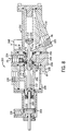
- FIGS. 6 and 7 illustrate a water cooled liquid fuel actuated distributor embodiment of the valve 100 .
- This distributor valve 100 has a valve housing 102 with a flanged end 104 that is designed to bolt onto another component of the liquid fuel system of the turbine, for example a liquid fuel metering valve (not shown) that controls liquid fuel flow to the distributor valve 100 .
- the flanged end 104 of the housing 102 has a central axial fuel inlet port 106 with an inlet filter or screen 108 and an array of angularly spaced apart fuel outlet ports 110 .
- There should be one outlet port for each combustion can of the turbine which typically number 5 or 6, however, only two are shown (one being in phantom lines).
- the fuel inlet port 106 communicates with the plurality of fuel outlet ports 110 through a valve chamber 112 as well as through a plurality of small flow orifices 114 (and associated passageways), one orifice being associated with each of fuel outlet port.
- a small module 116 threads or presses into each orifice 114 so that the valve can be designed according to the intended application.
- the module can be a small cup with a small through passageway so that the associated fuel outlet port is always in communication with the fuel inlet via that flow orifice, or it can be a plug with no passageway which blocks that flow orifice.
- either no liquid fuel or a small volume of liquid fuel can be sent to the associated combustor can nozzle during light-off of the turbine.
- the quantity and designated ones of the combustor can nozzles receiving liquid fuel at light-off can be selected simply by selecting the appropriate module. Further, the volume and flow rate of the light-off fuel can be selected by using modules with larger or smaller passageways.
- the distributor valve 100 is to be used with a separate liquid fuel metering valve which can provide fuel shut-off to prevent any liquid fuel from passing through to the combustor cans.
- liquid fuel When liquid fuel is supplied to the distributor fuel inlet port 106 , it will flow under pressure through one or more flow orifices 114 (depending on the configuration of the associated modules 116 ) and through the associated fuel outlet port(s) 110 to the turbine combustor can(s). It will do this (for engine light-off) regardless of the position of a poppet 120 , that is when the poppet 120 is in either the closed position shown in FIG. 6 or the open position shown in FIG. 7 .
- An elongated guide 130 connects to the poppet 120 and extends back through the center of the return springs.
- a stationary retainer 132 backs up inner 134 and outer 136 sleeves having flanges against which the back ends of the respective inner and outer return springs press.
- the forward end of the inner return spring presses against a flange of the guide 130 while the outer return spring presses against a flange of a sliding retainer 138 which is pressed by the spring in abutment with the poppet 120 .
- the periphery of the poppet 120 is sealed by a high temperature seal 140 , for example, made of a graphite filled Teflon. It should be noted that the outer spring (and sliding retainer) could be eliminated if sufficient cooling can be achieved to allow use of a different seal construction, either fixed or sliding, which could be assembled and secured without use of the retainer.
- the valve housing defines a water cooling circuit which begins and ends at water supply 142 and return 144 ports (shown in phantom), which again are tangential to the valve chamber to induce a swirling flow into the valve chamber.
- the coolant flows within the valve chamber and alongside the interior components of the valve behind the front face of the poppet 120 .
- the seal 140 thus keeps liquid fuel isolated from the coolant, which is at low pressure (about 10 psi) relative to the liquid fuel, which realizes pressures exceeding 1,000 psi during operation of the turbine. Good heat transfer is achieved by winding the coolant through the housing and interior of the valve chamber wherein the coolant directly contacts the length of the guide and much of the back side surface of the poppet.
- the coolant flows in close proximity to the seal as well. The cooling will thus prolong the life of the working components and provide for more consistent operation by reducing coke deposits on the metering surfaces of the distributor valve.
- the distributor valve also has an interstitial vent 150 that connects a widened collection area 152 of the valve chamber behind the metering face of the poppet with one of the fuel outlet ports, preferably the lowermost outlet port to allow for gravity draining.
- This enlarged area is designed to collect any liquid fuel (which is at very high pressures) leaking past the metering face of the poppet and allow it to be drawn into the designated outlet port.
- FIGS. 8-10 illustrate a water cooled combination purge and distributor valve.
- a non-cooled combination valve is shown and described in U.S. Pat. No. 6,931,831, which is assigned to the assignee of the present invention, the entire disclosure of which is hereby incorporated by reference as though fully set forth herein. That patent provides a very detailed description of a non-cooled combined purge air and distributor valve, albeit with fuel recirculation, for a dual fuel gas turbine and thus this description will address the construction and operation of the valve only briefly.
- the combination valve 200 is a water cooled purge air and distributor valve.
- the valve housing 202 is formed of a pilot air section 204 , a liquid fuel inlet section 206 , a distributor section 208 and a purge air section 210 . These sections are connected together to define an elongated valve chamber 212 in which a spool valve 214 with two tapered metering ends is disposed.
- the spool valve 214 can be driven actively by pilot air flowing through pilot air inlet port 216 and acting against spring biased piston 218 which has a rod 220 that can abut one end of the spool valve 214 to move it against its return spring 222 .
- the enlarged spool body slidably seals against one or both of two high temperature annular seals 223 to isolate the purge air from the liquid fuel during any position of the spool valve.
- the spool valve 214 and piston rod 220 are in abutment in a liquid fuel shut-off position shown in FIG. 8 , in which the air can flow through a purge air circuit through purge air inlet port 225 , the valve chamber and out the several (preferably six) outlet ports 224 to purge the combustor cans (not shown).
- the arrows labeled “PA” illustrate the purge air circuit flow path.
- the forces of the pilot air and/or the liquid fuel move the spool valve to a burner light-off position shown in FIG. 9 in which the purge air inlet port is no longer in communication with the outlet ports and a liquid fuel inlet port 226 is in communication with one or more of the outlet ports 224 through one or one or more of the several (again preferably six) small flow orifices 228 in which modules 230 are disposed.
- the outlet ports, flow orifices and modules are generally the same and provide the same staged fuel flow benefits as described above with the dedicated water cooled distributor valve, albeit the spool valve opens and closes the flow orifices relative to the fuel inlet (rather than having them always open to the fuel inlet as in the aforementioned distributor valve).
- the arrows labeled “F” in FIG. 9 illustrate the liquid fuel circuit as it is during light-off.
- the spool valve is further opened passively by fuel pressure alone to the sustained combustion position shown in FIG. 10 in which the liquid fuel inlet port is in full communication with all of the outlet ports.
- the arrows labeled “F” in FIG. 10 illustrate the path of the liquid fuel circuit during sustained liquid fuel operation of the turbine.
- the liquid fuel inlet 206 , distributor 208 and purge air 210 sections of the valve housing also form the water cooling circuit of the valve 200 , which is designated by the arrows labeled “W” in the FIGS. 8-10 .
- the coolant flows through from water supply port 240 into an annular cavity 242 in the liquid fuel inlet section 206 of the housing. Coolant then flows through six axial passages 244 (two shown in phantom) and another annular cavity 246 in the purge air section where it exits through water return port 248 .
- the water supply and return ports are tangentially disposed to induce a rotational flow inside the valve.
- the combining valve provides adequate cooling of the valve chamber and working components, particularly the spool valve and its seals which come into direct contact with the high pressure and temperature liquid fuel, so as to reduce or eliminate the formation of coke deposits in critical areas of the valve, thereby providing a more reliable valve for use in the extreme gas turbine environment.
- valve could also take the form of a water cooled 3-way purge valve, which is generally similar to the aforesaid combining valve without the distributor section.
- a non-cooled 3-way purge valve is disclosed in U.S. Pat. No. 6,050,081, which is assigned to the assignee of the present invention, and the entire disclosure of which is hereby incorporated by reference as through fully set forth herein, especially FIGS. 1-3 and the description at col. 2, line 55 to col. 4, line 35.
- the present invention would thus include a liquid fuel circuit and a purge air circuit controlled by a valve actuated by pilot air (active) or liquid fuel (passive).
- the valve is a dual acting spool valve designed to isolate and alternatively meter the liquid fuel and the purge air.
- the valve would further include a water cooling circuit running through the valve housing with tangential supply and return ports.
- the cooling circuit could be formed by a jacket surrounding the valve body or it could be integral with the valve body.
- the cooling circuit would extend about the valve chamber, for example in a spiral path, in close proximity to the valve member and seals.
Abstract
A water cooled valve is provided in the form of a check valve, an air purge valve, a distributor valve, a combination air purge and distributor valve and the like for use in the liquid fuel system of a gas turbine. A movable valve member controls the flow of fluid through the valve's fuel circuit. A separate cooling circuit circulates cooling water through the valve near or alongside the valve member. The water is of a lower temperature than the high temperature liquid fuel, and thereby carries away heat transferred to the valve by the fuel. In one form, the cooling circuit is formed in part by a helical groove in the periphery the valve body housing the valve member. A sealed water jacket surrounds the valve body and has dedicated supply and return ports for coupling the valve to a water supply via water lines. The water ports are positioned tangentially to induce swirling flow inside the valve.
Description
This application is a divisional of U.S. patent application Ser. No. 10/937,711, allowed on Feb. 24, 2009, filed Sep. 9, 2004, now U.S. Pat. No. 7,527,068 which claims benefit to U.S. Provisional Application No. 60/501,250 filed Sep. 9, 2003, and which is a continuation-in-part of U.S. patent application Ser. No. 10/462,295, filed Jun. 16, 2003, now U.S. Pat. No. 6,931,831, issued Aug. 23, 2005, which claims benefit to U.S. Provisional Application No. 60/389,827, filed Jun. 18, 2002.
Not applicable.
1. Technical Field
The present invention relates to fuel delivery systems for land and air based gas turbine engines, and in particular to liquid fuel control valves for turbine engines.
2. Description of the Related Art
Gas turbine engines have a set of rotating turbine blades that compress air leading to a combustion chamber into which fuel is injected and ignited. Fuel is delivered through metering orifices to burners in the combustion chamber under pressure through a fuel line. Combustion of the fuel turns a downstream set of blades from which energy is extracted and which can also be used to drive the compressor blades. Gas turbines used in power generation have large diameter blades and an array of combustion cans each with several burner nozzles that ignite the fuel at light-off and sustain combustion during operation. Many of these are dual fuel turbines (e.g., F-Class gas turbines) in which sustained operation can be achieved by burning either a liquid or a gaseous fuel. Diesel and heavy distillate fuel oils are common liquid fuels in power generation applications.
The combustion cans of the turbine are high pressure and temperature environments. It is typical for the environment surrounding the combustion cans to reach temperatures of 400° F., and for the combustion chamber temperature to near 2,000° F. The liquid fuel is consumed at a rate of about 20 gallons per minute at a high fuel pressure of about 1200 psig. This extreme environment is very hard on the fuel control components of the turbine fuel system, particularly for dual fuel turbines in which the during sustained gaseous burn, the liquid fuel system remains inoperable for long periods of time. The primary concern is the formation of the coke, or the tarry deposits left after the distillate or volatile components of the fuel are driven off by heat, on the metering orifices and other working surfaces of the liquid fuel control components. Coke deposits arise primarily from the presence of residual fuel left in the fuel atomizer, burner nozzles, control valves, fuel manifolds and other components subjected to the high heat of combustion. Residual liquid fuel left in the liquid fuel control components during gaseous operation will begin to coke at temperatures of about 250-280° F. in the presence of oxygen, which are well under the combustion temperature.
To evacuate the residual fuel, the fuel valves, burner nozzles and other components are purged with purge air bled from the turbine compressors or from an independent source. While the purge air coming from the compressors is hot, it is cooler than the combustion chamber temperatures so that it also cools the burner nozzles. Thus, air purging is necessary to prevent the burner nozzles from being damaged as well as to ensure that the system orifices and valves are clear of such deposits which could inhibit proper conduit of the fuel when the engine is returned to fuel mode.
An effective three-way purge valve is disclosed in U.S. Pat. No. 6,050,081, assigned to the assignee of the present invention and hereby incorporated by reference as though fully set forth herein. That valve has a spool valve that shuttles between positions alternatively blocking the combustion can(s) from either the purge air line or the fuel line. The spool is biased to close off the fuel line and is urged to open the fuel line by a pilot air actuated piston. Thus, when fuel is to be closed off from the engine, the spool valve will return to its initial position thereby allowing the burner nozzles and the downstream side of the spool to be purged to reduce or eliminate coking in these areas.
Even with good air purging, coking can still be a problem. Not all of the components in the fuel system subjected to high temperatures, for example fuel check and cut-off valves, are often not able to be purged because they may be providing the barrier between the fuel and air streams. And, even those components that are air purged, some amount of residual liquid fuel may remain in the small internal chambers and passageways of the valves or other components of the fuel system. Moreover, since the air purge control valves may themselves be located at or near the combustion cans, they too are subject to the adverse affects of coking.
To further reduce the effects of coking, U.S. Pat. No. 6,729,135 discloses a system and method of circulating the liquid fuel through a heat exchanger to cool the temperature of the liquid fuel distillate during operation of the turbine in gaseous fuel mode. Coking is thus reduced in larger part by keeping much of the liquid fuel distillate temperature below the coking threshold temperature. However, this system requires a heat exchanger and either a separate fuel recirculation pump or increased duty on the main fuel pump. Moreover, because the recirculation lines carry liquid fuel, these lines, along with any recirculation control components, present yet another location for coking to occur when the recirculation system is not operating. To avoid this, during liquid fuel operation some of the liquid fuel must be made to bypass the combustor to flow through the recirculation system. Intermittent operation of the recirculation system is also possible, but only to the extend that sufficiently cool fuel temperatures can be maintained.
The present invention provides liquid fuel valves for use in the extreme temperature and pressure conditions of land and air based gas turbine engine applications. The compact valve package is cooled by a dedicated liquid coolant circuit circulating relatively low temperature water past critical parts of the valve to provide more consistent operation and reduce coking.
Generally, the invention provides a water cooled liquid fuel valve. The valve has a housing defining a fuel flow path including a valve chamber, a fuel inlet port and a fuel outlet port. A movable valve member is disposed in the valve chamber such that in a closed position it disrupts flow of fuel from the inlet to the outlet port. A cooling water circuit allows for circulating water of lesser temperature than the liquid fuel along parts of the valve housing and/or the valve member.
Dedicated water supply and return ports are used to connect the valve to a water supply via suitable lines. Preferably, the water return and supply ports are tangential to the valve chamber so that a swirling motions is effected inside the valve which aids in distributing the coolant along the interior of the valve and thereby improves heat transfer.
Depending on the construction of the valve, the cooling water circuit can introduce the cooling water into the valve chamber so as to come in direct contact with the valve member. For example, the valve member can be a poppet type valve with an elongated guide member. In this case, the cooling water can circulate through the valve chamber to cool both the housing and the entire length of the guide member as well as the back side of the poppet, the front side of which comes into direct contact with the high temperature fuel. The cooling water is preferably at low pressure so as not to affect the movement of the valve member.
The cooling water circuit can be designed to follow a spiral or helical path about at least a portion of the valve chamber. This circuit configuration effects an annular distribution of the coolant to better effect heat transfer, and thus further the pre-swirl induced by the tangential water supply port. The helical circuit can be formed in an suitable manner. In one preferred form, it is formed between the valve body housing the movable valve member and a water jacket. The water jacket has the water supply and return ports. It surrounds much or all of the valve body and is made to seal off the water circuit from the exterior. For example, a pair of high temperature seals can be used at each side of the water circuit which seat against the outer periphery of the valve body and the interior of the water jacket. Preferably, this is a slidable seal to permit the water jacket to translate or rotate relative to the valve body for slight position adjustment. The helical path itself can be formed by a continuous spiral groove at the outer periphery of the valve body or the interior of the water jacket. The groove, of course, is in communication with the water supply and return ports, preferably with one end of the groove at the supply port and the other end at the return port.
With the present invention, better performing valves of various constructions can be used in the extreme environment of a combustion area of a gas turbine engine to accomplish various objectives. For example, the valve can be a check valve used to prevent the back flow of liquid fuel from the burner nozzles, the valve can be a distributor valve for selectively and variably sending liquid fuel to the array of burner nozzles in the combustor cans of the turbine engine. The valve can be a purge valve, such as a three-way purge valve, that alternatively meters liquid fuel to the burner nozzles during liquid fuel operation of the gas turbine or purge air for the purpose of preventing coking and other evacuating liquid fuel from the burner nozzles during gaseous fuel operation or shut-down. Still further, the valve can be a combination purge air and distributor valve, providing these functions in a single unit.
Thus, in one aspect the present invention provides a water cooled liquid fuel check valve. The check valve can have a water jacket, having tangential water supply and return ports, that fits over a valve body having a spring biased fuel actuated valve member biased to close off communication between the fuel inlet and outlet ports. The valve body has an annular groove forming the cooling water circuit between the valve body and the water jacket in communication with the water supply and return ports. The valve can also have a special baffle member with a series of openings, some of which are axially aligned with the poppet valve member allowing liquid fuel to flow into a primary metering chamber. The baffle member also has radial openings to a stem with an axial passageway leading a portion of the fuel to a Helmhotz type resonance chamber, which preferably is defined by the interior of the poppet, to dampen pressure oscillations in the exiting fuel flow.
In another aspect, the present invention is a water cooled liquid fuel distributor valve regulating liquid fuel flow through one or more of a plurality of fuel outlets. The valve has a dedicated water cooling circuit with tangential supply and return ports, which in a preferred form can be in communication with the valve chamber to directly cool the moveable valve member. The distributor valve is designed to mount to and receive the output of a metering valve that controls shut off of the liquid full flow. The distributor valve is used to distribute the metered fuel to one or more of the array of burner nozzles in one or more combustion cans of the gas turbine. The distributor thus has a central fuel inlet port and a radial arrangement of fuel outlet ports, for example six fuel outlet ports arranged about fuel inlet port axis. The movable valve member opens and closes each of these primary fuel outlet ports for sustained liquid fuel operation of the gas turbine. However, each outlet port has parallel flow paths, the primary path being the large opening of the outlet port and the second path being a small flow orifice associated with each fuel outlet port. In this embodiment of the valve, these flow orifices are always in communication with the fuel inlet port even when the valve member closes off the primary flow path through the fuel outlet ports. The flow orifices are used to control the flow volume and rate at engine light-off, which typically requires less liquid fuel than during sustained combustion. The flow orifices can receive small modules that either define a plug or a flow passage of a diameter selected to achieve the necessary flow rate and volume. If a flow orifice is plugged by a module the associated burner nozzle will not receive fuel. Thus, this arrangement provides for selective flow rate/volume and the ability to send fuel to none or a selected one or subset of the burner nozzles.
In yet another aspect, the present invention provides a liquid fuel metering valve with a dedicated fluid coolant circuit and purge air and/or distributor sections. The valve includes three isolated flow circuits, namely a liquid fuel circuit, a cooling fluid circuit and a purge air circuit. In particular, the liquid fuel circuit includes a fuel inlet port, a fuel only section of the valve chamber and an outlet port. The purge air circuit includes an air inlet port, an air only section of the valve chamber and the outlet port. The cooling fluid circuit includes cooling fluid supply and return ports for circulating cooling fluid of proximate the valve member. The coolant circuit is preferably entirely separate passageways, for example having a spiral or helical section between the valve body and a water jacket. However in a preferred 3-way metering/purge valve construction, the fuel and purge air circuits, preferably share one or more passageways and the outlet port leading to the combustor(s) while the valve member isolates the air flow form the fuel flow so that these streams do not mix. The valve thus can be operated to meter fuel to the burner nozzle during sustained liquid fuel operation and alternatively to purge the downstream fuel lines and burners with air to cool them and extricate residual liquid fuel to prevent coking during shut down and gaseous fuel operation of the turbine.
In still another aspect, the valve is a fluid cooled combined purge air and distributor valve. In this case, the housing defines the aforementioned three flow circuits as well as a distributor section having a plurality of outlet ports which make up part of the liquid fuel circuit. Also, the liquid fuel circuit preferably includes a plurality of flow orifices disposed within the liquid fuel circuit between the fluid inlet port and an associated one of the plurality of outlet ports. At least one of the flow orifices receives a module that mounts to the valve housing. Each module can define a flow passageway or a plug blocking the flow of liquid fuel through the associated flow orifice. The valve is arranged so that the liquid fuel inlet port is in communication with the plurality of flow orifices when the valve member is in a first, lesser open position and in communication with the plurality of flow orifices and the plurality of outlet ports when the valve member is in a second, fully open position. This arrangement provides at least two benefits. First, it provides for a lesser volume of liquid fuel to flow to the turbine atomizer and burners, for example during light-off. Second, the modules allow the valve to be configured to flow liquid fuel to one or sub-set of burner nozzles designated to begin combustion at light-off.
These and still other advantages of the invention will be apparent from the detailed description and drawings. What follows are preferred embodiments of the present invention. To assess the full scope of the invention the claims should be looked to as the preferred embodiments are not intended as the only embodiments within the scope of the invention.
The present invention provides a non-fuel liquid cooled liquid fuel valve for use in the extreme temperature and pressure environment of the fuel system of an air or ground gas turbine engine. The valve can take the form of a check valve, an air purge valve, a distributor valve, a combination air purge and distributor valve and the like. In any form, a movable valve member controls the flow of liquid fuel through the valve's fuel circuit and a separate cooling circuit circulates coolant through the valve near or alongside the valve member. Although not shown, for each embodiment of the valve suitable lines or conduit couple the valve to a water supply, which can be continuous cool water supply or a recirculated supply tank with or without external cooling. The coolant is any suitable non-fuel fluid, preferably water and preferably of a lower temperature than the liquid fuel. For simplicity, the following valve embodiments will be described as being water cooled.
The liquid fuel flow circuit of the check valve passes between the fuel inlet 38 and outlet 40 ports, the valve chamber 36 as well as the baffle 48, guide 44 and retainer 56. In particular, the baffle 48 has a circular portion with a series of axial openings 62 allowing the liquid fuel to flow into a primary metering chamber 64 within the guide 44. The baffle 48 also has radial openings 66 that open to an elongated passageway 68 in the baffle stem 46 which leads to a Helmholtz resonance chamber 70, which acts as an accumulator to reduce pressure oscillations in the fuel. The end of the guide 44 has a small axial orifice 72 through which the liquid fuel flows to pressurize and drive the poppet 42 against the return spring 60 to move the tapered circular metering edge 74 to open radial metering orifices 76 in the guide 44. Liquid fuel then flows into the valve chamber and through orifices 78 in the retainer 56 and then out the fuel outlet 40.
As mentioned, the distributor valve 100 is to be used with a separate liquid fuel metering valve which can provide fuel shut-off to prevent any liquid fuel from passing through to the combustor cans. When liquid fuel is supplied to the distributor fuel inlet port 106, it will flow under pressure through one or more flow orifices 114 (depending on the configuration of the associated modules 116) and through the associated fuel outlet port(s) 110 to the turbine combustor can(s). It will do this (for engine light-off) regardless of the position of a poppet 120, that is when the poppet 120 is in either the closed position shown in FIG. 6 or the open position shown in FIG. 7 . As the pressure of the liquid fuel builds, it will act on the face of the poppet 120 and drive it back against inner 122 and outer 124 return springs so that liquid fuel can flow through the valve chamber 112 and through the larger passageways 126 leading to the fuel outlet ports 110. An elongated guide 130 connects to the poppet 120 and extends back through the center of the return springs. A stationary retainer 132 backs up inner 134 and outer 136 sleeves having flanges against which the back ends of the respective inner and outer return springs press. The forward end of the inner return spring presses against a flange of the guide 130 while the outer return spring presses against a flange of a sliding retainer 138 which is pressed by the spring in abutment with the poppet 120. The periphery of the poppet 120 is sealed by a high temperature seal 140, for example, made of a graphite filled Teflon. It should be noted that the outer spring (and sliding retainer) could be eliminated if sufficient cooling can be achieved to allow use of a different seal construction, either fixed or sliding, which could be assembled and secured without use of the retainer.
The valve housing defines a water cooling circuit which begins and ends at water supply 142 and return 144 ports (shown in phantom), which again are tangential to the valve chamber to induce a swirling flow into the valve chamber. The coolant flows within the valve chamber and alongside the interior components of the valve behind the front face of the poppet 120. The seal 140 thus keeps liquid fuel isolated from the coolant, which is at low pressure (about 10 psi) relative to the liquid fuel, which realizes pressures exceeding 1,000 psi during operation of the turbine. Good heat transfer is achieved by winding the coolant through the housing and interior of the valve chamber wherein the coolant directly contacts the length of the guide and much of the back side surface of the poppet. The coolant flows in close proximity to the seal as well. The cooling will thus prolong the life of the working components and provide for more consistent operation by reducing coke deposits on the metering surfaces of the distributor valve.
The distributor valve also has an interstitial vent 150 that connects a widened collection area 152 of the valve chamber behind the metering face of the poppet with one of the fuel outlet ports, preferably the lowermost outlet port to allow for gravity draining. This enlarged area is designed to collect any liquid fuel (which is at very high pressures) leaking past the metering face of the poppet and allow it to be drawn into the designated outlet port. After the turbine is switched to gaseous fuel mode and liquid fuel is no longer flowing through the distributor valve, residual liquid fuel in the valve chamber and in the collection area will drain to the outlet port. If the distributor valve is coupled to a purge valve, the pressurized purge air will purge the valve chamber and draw any residual fuel in the collection area out through the outlet port.
The combination valve 200 is a water cooled purge air and distributor valve. The valve housing 202 is formed of a pilot air section 204, a liquid fuel inlet section 206, a distributor section 208 and a purge air section 210. These sections are connected together to define an elongated valve chamber 212 in which a spool valve 214 with two tapered metering ends is disposed. The spool valve 214 can be driven actively by pilot air flowing through pilot air inlet port 216 and acting against spring biased piston 218 which has a rod 220 that can abut one end of the spool valve 214 to move it against its return spring 222. The enlarged spool body slidably seals against one or both of two high temperature annular seals 223 to isolate the purge air from the liquid fuel during any position of the spool valve.
The spool valve 214 and piston rod 220 are in abutment in a liquid fuel shut-off position shown in FIG. 8 , in which the air can flow through a purge air circuit through purge air inlet port 225, the valve chamber and out the several (preferably six) outlet ports 224 to purge the combustor cans (not shown). The arrows labeled “PA” illustrate the purge air circuit flow path.
The forces of the pilot air and/or the liquid fuel move the spool valve to a burner light-off position shown in FIG. 9 in which the purge air inlet port is no longer in communication with the outlet ports and a liquid fuel inlet port 226 is in communication with one or more of the outlet ports 224 through one or one or more of the several (again preferably six) small flow orifices 228 in which modules 230 are disposed. Note that the outlet ports, flow orifices and modules are generally the same and provide the same staged fuel flow benefits as described above with the dedicated water cooled distributor valve, albeit the spool valve opens and closes the flow orifices relative to the fuel inlet (rather than having them always open to the fuel inlet as in the aforementioned distributor valve). The arrows labeled “F” in FIG. 9 illustrate the liquid fuel circuit as it is during light-off.
With continued liquid fuel flow the spool valve is further opened passively by fuel pressure alone to the sustained combustion position shown in FIG. 10 in which the liquid fuel inlet port is in full communication with all of the outlet ports. The arrows labeled “F” in FIG. 10 illustrate the path of the liquid fuel circuit during sustained liquid fuel operation of the turbine.
The liquid fuel inlet 206, distributor 208 and purge air 210 sections of the valve housing also form the water cooling circuit of the valve 200, which is designated by the arrows labeled “W” in the FIGS. 8-10 . Specifically, the coolant flows through from water supply port 240 into an annular cavity 242 in the liquid fuel inlet section 206 of the housing. Coolant then flows through six axial passages 244 (two shown in phantom) and another annular cavity 246 in the purge air section where it exits through water return port 248. As before, the water supply and return ports are tangentially disposed to induce a rotational flow inside the valve. The combining valve provides adequate cooling of the valve chamber and working components, particularly the spool valve and its seals which come into direct contact with the high pressure and temperature liquid fuel, so as to reduce or eliminate the formation of coke deposits in critical areas of the valve, thereby providing a more reliable valve for use in the extreme gas turbine environment.
Although not shown, the valve could also take the form of a water cooled 3-way purge valve, which is generally similar to the aforesaid combining valve without the distributor section. A non-cooled 3-way purge valve is disclosed in U.S. Pat. No. 6,050,081, which is assigned to the assignee of the present invention, and the entire disclosure of which is hereby incorporated by reference as through fully set forth herein, especially FIGS. 1-3 and the description at col. 2, line 55 to col. 4, line 35.
The present invention would thus include a liquid fuel circuit and a purge air circuit controlled by a valve actuated by pilot air (active) or liquid fuel (passive). Preferably, the valve is a dual acting spool valve designed to isolate and alternatively meter the liquid fuel and the purge air. The valve would further include a water cooling circuit running through the valve housing with tangential supply and return ports. The cooling circuit could be formed by a jacket surrounding the valve body or it could be integral with the valve body. Preferably, the cooling circuit would extend about the valve chamber, for example in a spiral path, in close proximity to the valve member and seals.
It should be appreciated that merely preferred embodiments of the invention have been described above. However, many modifications and variations to the preferred embodiments will be apparent to those skilled in the art, which will be within the spirit and scope of the invention. Therefore, the invention should not be limited to the described embodiments. To ascertain the full scope of the invention, the following claims should be referenced.
Claims (20)
1. A combination distributor purge valve unit for a turbine engine, comprising:
a fuel section having a fuel inlet;
a purge air section having an air inlet;
a distributor section disposed between the fuel section and the purge air section and having a plurality of outlets;
a spool movable along a spool axis from a first position in which the plurality of outlets are in communication with the air inlet and closed off from the fuel inlet to a second position in which the plurality of outlets are in communication with the fuel inlet and closed off from the air inlet; and
a water cooling circuit in communication with a coolant supply port and a coolant return port defined at the exterior of the valve, the water cooling circuit having passageways within at least one of the fuel, purge air, and distributor sections and in contact with an internal component of the valve within an interior defined by the at least one fuel, purge air and distributor sections for carrying coolant that is isolated from the fuel and the purge air to receive and carry away heat from the internal component.
2. The valve of claim 1 , wherein the water cooling circuit effects rotational flow relative to the valve axis.
3. The valve of claim 2 , wherein the coolant supply and return ports are tangentially disposed on the valve housing with respect to the spool axis.
4. The valve of claim 1 , wherein the water cooling circuit passageways include multiple axial passageways that are defined by the distributor section.
5. The valve of claim 4 , wherein the water cooling circuit further includes an annular cavity in the fuel section and an annular cavity in the purge air section, such that each annular cavity communicates with each axial passageway.
6. The valve of claim 1 , wherein each of the plurality of outlets includes first and second passageways, the first and second passageways being in communication with the air inlet when the spool is in the first position and in communication with the fuel inlet when the spool is in the second position.
7. The valve of claim 6 , wherein the first passageways are fill nozzles and the second passageways are outlet orifices of greater bore diameter than the fill nozzles.
8. The valve of claim 1 , wherein the spool moves along the spool axis within a spool chamber extending within the fuel distributor and purge air sections and wherein the plurality of outlets are disposed about the spool axis so that the outlets extend radially from the spool chamber.
9. The valve of claim 8 , wherein the distributor section has six such outlets spaced equiangularly about the spool axis.
10. The valve of claim 1 , wherein a first annular seal is disposed between the plurality of outlets and the fuel inlet and a second annular seal is disposed between the plurality of outlets and the air inlet.
11. The valve of claim 10 , wherein the spool includes a valve section sized to mate with the first and second annular seals.
12. The valve of claim 1 , further including a pilot air section adjacent the fuel section and containing an actuator piston disposed along the spool axis operable by pilot air to move the spool away from the first position.
13. The valve of claim 1 , wherein the fuel section further includes a recirculation port in communication with the fuel inlet and an upstream side of a valve section of the spool through at least one internal passageway.
14. The valve of claim 1 , wherein the distributor section includes a mounting bore extending parallel to the spool axis.
15. The valve of claim 1 , wherein the fuel section includes a venturi passageway at the fuel inlet and a particle trap opposite the venturi passageway.
16. A combination distributor purge valve unit for a turbine engine with a valve housing, comprising:
a fuel section of the valve housing having a fuel inlet;
a purge air section of the valve housing having an air inlet;
a distributor section disposed between the fuel section and the purge air section of the valve housing and having a plurality of outlets;
a spool internal to the valve housing that is movable along a spool axis from a first position in which the plurality of outlets are in communication with the air inlet and closed off from the fuel inlet to a second position in which the plurality of outlets are in communication with the fuel inlet and closed off from the air inlet; and
a water cooling circuit internal to the valve housing in communication with a coolant supply port and a coolant return port, wherein the water of the cooling circuit has rotational flow relative to the valve axis and receives and carries heat away from the valve.
17. The valve of claim 16 , wherein the coolant supply and return ports are tangentially disposed to the valve housing.
18. A combination distributor purge valve for a turbine engine, comprising:
a fuel section having a fuel inlet;
a purge air section having an air inlet;
a distributor section disposed between the fuel section and the purge air section which includes six outlets spaced equiangularly in a radial fashion about the valve;
a spool movable along a spool axis for altering whether isolated fuel or isolated purged air communicates with the six outlets; and
a water cooling circuit internal to the valve in communication with a coolant supply port and a coolant return port for receiving and carrying heat away from the valve, the water cooling circuit having six axial passageways located in the distributor section, wherein the axial passageways are spaced equiangularly in a radial fashion about the spool axis such that only one axial passageway is located between two adjacent outlets and each axial passageway is isolated from the outlets.
19. The valve of claim 18 , wherein the water cooling circuit further includes an annular cavity in the fuel section and an annular cavity in the purge air section, such that the axial passageways communicate with both annular cavities.
20. The valve of claim 19 , wherein the coolant supply and return ports are tangentially disposed to the valve such that the coolant has rotational flow in the water cooling circuit.
Priority Applications (1)
| Application Number | Priority Date | Filing Date | Title |
|---|---|---|---|
| US12/421,385 US7874310B1 (en) | 2002-06-18 | 2009-04-09 | Water cooled liquid fuel valve |
Applications Claiming Priority (5)
| Application Number | Priority Date | Filing Date | Title |
|---|---|---|---|
| US38982702P | 2002-06-18 | 2002-06-18 | |
| US10/462,295 US6931831B2 (en) | 2002-06-18 | 2003-06-16 | Distributor purge valve |
| US50125003P | 2003-09-09 | 2003-09-09 | |
| US10/937,711 US7527068B2 (en) | 2002-06-18 | 2004-09-09 | Valve with swirling coolant |
| US12/421,385 US7874310B1 (en) | 2002-06-18 | 2009-04-09 | Water cooled liquid fuel valve |
Related Parent Applications (1)
| Application Number | Title | Priority Date | Filing Date |
|---|---|---|---|
| US10/937,711 Division US7527068B2 (en) | 2002-06-18 | 2004-09-09 | Valve with swirling coolant |
Publications (1)
| Publication Number | Publication Date |
|---|---|
| US7874310B1 true US7874310B1 (en) | 2011-01-25 |
Family
ID=46302791
Family Applications (2)
| Application Number | Title | Priority Date | Filing Date |
|---|---|---|---|
| US10/937,711 Expired - Lifetime US7527068B2 (en) | 2002-06-18 | 2004-09-09 | Valve with swirling coolant |
| US12/421,385 Expired - Lifetime US7874310B1 (en) | 2002-06-18 | 2009-04-09 | Water cooled liquid fuel valve |
Family Applications Before (1)
| Application Number | Title | Priority Date | Filing Date |
|---|---|---|---|
| US10/937,711 Expired - Lifetime US7527068B2 (en) | 2002-06-18 | 2004-09-09 | Valve with swirling coolant |
Country Status (1)
| Country | Link |
|---|---|
| US (2) | US7527068B2 (en) |
Cited By (16)
| Publication number | Priority date | Publication date | Assignee | Title |
|---|---|---|---|---|
| WO2014046849A1 (en) * | 2012-09-20 | 2014-03-27 | General Electric Company | Integrated actuator, gas turbine engine and coresponding operating method |
| JP5827751B2 (en) * | 2012-08-02 | 2015-12-02 | 日産自動車株式会社 | Valve and fuel cell system using the valve |
| US20160061337A1 (en) * | 2014-09-02 | 2016-03-03 | Plant Oil Powered Diesel Fuel Systems, Inc. | Dual Piston Valve for Flow Control of Two Distinct Liquid Fuels |
| US20160059690A1 (en) * | 2014-08-27 | 2016-03-03 | Oshkosh Corporation | Natural gas filling system for a vehicle |
| US9354141B1 (en) | 2013-06-17 | 2016-05-31 | Jansen's Aircraft Systems Controls, Inc. | Turbine liquid fuel simulator |
| US20160341428A1 (en) * | 2013-12-18 | 2016-11-24 | Ge Energy Products France Snc | Valve with integrated actuating device, notably for a combustion system |
| CN107806522A (en) * | 2017-11-25 | 2018-03-16 | 浙江杰特优动力机械有限公司 | A kind of steam-extracting type speed closes non-return valve and its method of work |
| WO2018160914A1 (en) * | 2017-03-03 | 2018-09-07 | Dixon Matthew R | Fluid system components with thermal conditioning passages |
| US10190498B1 (en) * | 2015-07-24 | 2019-01-29 | Jansen's Aircraft Systems Controls, Inc. | Valve with valve member cooling |
| EP3597874A1 (en) * | 2018-07-19 | 2020-01-22 | Hamilton Sundstrand Corporation | Active clearance control valve with thermal shield and method for manufacturing the same |
| CN110886655A (en) * | 2019-11-22 | 2020-03-17 | 中国航发西安动力控制科技有限公司 | Valve for aeroengine boosting fuel system |
| USD886237S1 (en) | 2018-09-04 | 2020-06-02 | Swagelok Company | Thermal trace valve body |
| US10738746B1 (en) * | 2014-09-02 | 2020-08-11 | Alafei Foods Limited | Dual piston valve for flow control of two distinct liquid fuels |
| US11391214B2 (en) | 2019-05-15 | 2022-07-19 | Pratt & Whitney Canada Corp. | System and method for purging a fuel manifold of a gas turbine engine using a flow divider assembly |
| US11486303B2 (en) | 2019-05-15 | 2022-11-01 | Pratt & Whitney Canada Corp. | System and method for purging a fuel manifold of a gas turbine engine using a pump |
| US11536201B2 (en) | 2019-05-15 | 2022-12-27 | Pratt & Whitney Canada Corp. | System and method for purging a fuel manifold of a gas turbine engine through a flow divider valve |
Families Citing this family (20)
| Publication number | Priority date | Publication date | Assignee | Title |
|---|---|---|---|---|
| US7527068B2 (en) | 2002-06-18 | 2009-05-05 | Jansen's Aircraft Systems Controls, Inc. | Valve with swirling coolant |
| US7340939B2 (en) * | 2004-08-25 | 2008-03-11 | Jansen's Aircraft Systems Controls, Inc. | Emissions sampling valve |
| DE102004052500B4 (en) * | 2004-10-28 | 2013-06-20 | Voss Automotive Gmbh | Mounting kit for a vehicle air suspension system with a switchable additional air spring volume and method for controlling the air spring system |
| US7464722B2 (en) * | 2005-08-05 | 2008-12-16 | Jansen's Aircraft Systems Controls, Inc. | Fluid proportioning valve |
| US8066474B1 (en) * | 2006-06-16 | 2011-11-29 | Jansen's Aircraft Systems Controls, Inc. | Variable guide vane actuator |
| US8104258B1 (en) | 2007-05-24 | 2012-01-31 | Jansen's Aircraft Systems Controls, Inc. | Fuel control system with metering purge valve for dual fuel turbine |
| US8950425B1 (en) | 2008-01-11 | 2015-02-10 | Jansen's Aircraft Systems Controls, Inc. | Combining valve with fuel relief and sealing |
| US8053127B2 (en) * | 2008-04-23 | 2011-11-08 | GM Global Technology Operations LLC | Fuel cell cooling tank assembly |
| US20090269639A1 (en) * | 2008-04-23 | 2009-10-29 | Gm Global Technology Operations, Inc. | Fuel cell cooling tank assembly |
| US8656698B1 (en) | 2008-05-28 | 2014-02-25 | Jansen's Aircraft System Controls, Inc. | Flow controller and monitoring system |
| US8528315B2 (en) * | 2008-10-30 | 2013-09-10 | General Electric Company | Air cooling apparatus for a purge valve |
| US8316875B2 (en) * | 2008-12-30 | 2012-11-27 | General Electric Company | Methods, apparatus and/or systems relating to fuel delivery systems for industrial machinery |
| US8322361B2 (en) * | 2008-12-30 | 2012-12-04 | General Electric Company | Methods, apparatus and/or systems relating to controlling flow through concentric passages |
| US20110100015A1 (en) * | 2009-11-05 | 2011-05-05 | General Electric Company | Gas turbine system to inhibit coke formation and methods of use |
| US9127605B2 (en) * | 2012-03-21 | 2015-09-08 | Ford Global Technologies, Llc | Vapor recovery system purge valve and method |
| US9732864B2 (en) * | 2014-05-14 | 2017-08-15 | Hamilton Sundstrand Corporation | Contamination resistant cartridge valve |
| EP3575650A1 (en) * | 2018-05-29 | 2019-12-04 | Microtecnica S.r.l. | Self venting pressure relief valve |
| FR3093535B1 (en) * | 2019-03-04 | 2021-06-25 | Illinois Tool Works | COOLING SYSTEM OF A MOTOR VEHICLE |
| US11254477B2 (en) * | 2019-10-16 | 2022-02-22 | Morgan Specialty Services, Inc. | Extraction pressure vessel, method of manufacture, method of use |
| US20230160479A1 (en) * | 2021-11-22 | 2023-05-25 | General Electric Company | Systems and methods for purging liquid from a liquid fuel supply system |
Citations (60)
| Publication number | Priority date | Publication date | Assignee | Title |
|---|---|---|---|---|
| US698474A (en) | 1901-10-25 | 1902-04-29 | Firm Of Vereinigte Maschinenfabrik Augsburg And Maschinen Baugesellschaft Nuernberg A G | Water-cooled valve. |
| US856538A (en) | 1905-01-25 | 1907-06-11 | Bullock Electric Mfg Co | Shaft-oscillator. |
| US1013867A (en) | 1910-12-24 | 1912-01-09 | Charles T Denker | Exhaust-valve mechanism. |
| US2505613A (en) | 1948-03-16 | 1950-04-25 | Victor W Farris | Safety valve for viscous fluids |
| US2770945A (en) | 1953-08-17 | 1956-11-20 | United Aircraft Corp | Jump-type flow divider for gas turbine power plant fuel system |
| US3038487A (en) | 1960-11-02 | 1962-06-12 | Lawrence H Gardner | Shuttle valve |
| US3139908A (en) | 1961-11-20 | 1964-07-07 | Hough Co Frank | Valve for hydraulically operated clutches |
| US3338257A (en) | 1964-05-22 | 1967-08-29 | Westinghouse Air Brake Co | Double check valve |
| US3584194A (en) | 1969-05-23 | 1971-06-08 | Aro Corp | Fluid heating techniques |
| US3632080A (en) | 1969-05-12 | 1972-01-04 | Louis T King | Pressure-balanced flapper valve |
| US3683966A (en) | 1970-04-02 | 1972-08-15 | Offshore Systems Inc | Three position valve |
| US3703185A (en) | 1970-04-07 | 1972-11-21 | E Systems Inc | Force balancing flapper valve |
| US3901269A (en) | 1973-08-14 | 1975-08-26 | Controls Southeast Inc | Jacket construction for fluid flow fittings |
| US4027474A (en) | 1976-03-05 | 1977-06-07 | United Technologies Corporation | Fuel prefill and distributor valve construction |
| US4041695A (en) | 1975-11-21 | 1977-08-16 | The Garrett Corporation | Fuel system pneumatic purge apparatus and method |
| US4095418A (en) | 1975-10-28 | 1978-06-20 | Stal-Laval Turbin Ab | Fuel flushing from injector for combustion chamber |
| US4206595A (en) | 1978-04-21 | 1980-06-10 | United Technologies Corporation | Fuel collecting and recycling system |
| US4222405A (en) | 1978-07-12 | 1980-09-16 | Rosenblad Corporation | Pressure vacuum breaker |
| US4327772A (en) | 1979-02-23 | 1982-05-04 | Aisin Seiki Kabushiki Kaisha | Valve device for controlling flow of fluid |
| US4344453A (en) | 1977-01-29 | 1982-08-17 | Otto Tuchenhagen Gmbh & Co. Kg | Pipeline switch with leakage control and cleanable leakage cavity |
| US4359929A (en) | 1979-08-23 | 1982-11-23 | United Technologies Corporation | Negative rate compensated hydraulic servo system |
| US4375873A (en) | 1980-10-23 | 1983-03-08 | Nippondenso Co., Ltd. | Temperature responsive valve |
| US4467957A (en) | 1982-09-29 | 1984-08-28 | Bucheit Frederick C | Flue flow regulator |
| US4501298A (en) | 1981-09-11 | 1985-02-26 | Aisin Seiki Kabushiki Kaisha | Solenoid actuated valve device |
| US4531587A (en) | 1984-02-22 | 1985-07-30 | Baker Oil Tools, Inc. | Downhole flapper valve |
| US4583570A (en) | 1984-10-15 | 1986-04-22 | Foster Wheeler Energy Corporation | Liquid cooled ball valve |
| US4633939A (en) | 1982-02-11 | 1987-01-06 | Modine Manufacturing | Heat transfer device for oil temperature regulator |
| US4687055A (en) | 1986-04-07 | 1987-08-18 | Leggett Henry H | Wire-line controlled down-hole shut-in tool for wells |
| US4760696A (en) | 1985-09-04 | 1988-08-02 | Rolls-Royce Plc | Fuel system for gas turbine engines |
| US5014738A (en) | 1988-07-12 | 1991-05-14 | C.J.S. Sciences Limited | Valve |
| US5062445A (en) | 1990-08-24 | 1991-11-05 | Triten Corporation | Water cooled gate valve |
| US5103777A (en) | 1989-02-07 | 1992-04-14 | Suzuki Jidosha Kogyo Kabushiki Kaisha | Fuel injection type multiple cylinder engine unit |
| US5245819A (en) | 1990-07-09 | 1993-09-21 | General Electric Company | Gas turbine engine fuel and hydraulic fluid pumping system |
| US5346175A (en) | 1992-12-31 | 1994-09-13 | Kelsey-Hayes Company | Variable assist steering control valve |
| US5391055A (en) | 1993-11-24 | 1995-02-21 | United Technologies Corporation | Propeller pitch change mechanism with impulse turbines |
| US5448890A (en) | 1994-03-24 | 1995-09-12 | United Technologies Corporation | Fuel supply apparatus with cooled check valve |
| US5762099A (en) | 1995-03-30 | 1998-06-09 | Iscor Limited | Valve system |
| US5809771A (en) | 1996-01-19 | 1998-09-22 | Woodward Governor Company | Aircraft engine fuel system |
| US5884483A (en) | 1996-04-18 | 1999-03-23 | Rolls-Royce Plc | Fuel system for a gas turbine engine |
| US6050081A (en) | 1997-02-12 | 2000-04-18 | Jansens Aircraft Systems Controls | Air purging fuel valve for turbine engine |
| US6182685B1 (en) | 1999-03-17 | 2001-02-06 | Wellman, Inc. | Injector structure for liquid additives |
| US6250063B1 (en) | 1999-08-19 | 2001-06-26 | General Electric Co. | Fuel staging apparatus and methods for gas turbine nozzles |
| US6253573B1 (en) | 1999-03-10 | 2001-07-03 | Specialty Equipment Companies, Inc. | High efficiency refrigeration system |
| US6385962B2 (en) | 1999-07-27 | 2002-05-14 | Alliedsignal Inc. | Fuel divider and ecology system for a gas turbine engine |
| US6412271B1 (en) | 1999-04-30 | 2002-07-02 | Lucas Industries Limited | Fuel control system |
| US20020084065A1 (en) | 2001-01-04 | 2002-07-04 | Tamin Enterprises | Fluid heat exchanger |
| US6427717B1 (en) | 1998-07-02 | 2002-08-06 | Tokyo Electron Limited | Process solution supplying apparatus and fluid passageway opening-closing valve device for process solution supplying apparatus |
| US6438963B1 (en) | 2000-08-31 | 2002-08-27 | General Electric Company | Liquid fuel and water injection purge systems and method for a gas turbine having a three-way purge valve |
| US6442925B1 (en) | 1999-08-31 | 2002-09-03 | Coltec Industries Inc | Manifold drain system for gas turbine |
| US6497100B2 (en) | 2000-03-16 | 2002-12-24 | Snecma Moteurs | Device for controlling the pressure and delivery of a fuel feed to a servovalve unit |
| US6609380B2 (en) | 2001-12-28 | 2003-08-26 | General Electric Company | Liquid fuel nozzle apparatus with passive protective purge |
| US6675583B2 (en) | 2000-10-04 | 2004-01-13 | Capstone Turbine Corporation | Combustion method |
| US6729135B1 (en) | 2002-12-12 | 2004-05-04 | General Electric Company | Liquid fuel recirculation system and method |
| US6807801B2 (en) | 2001-06-08 | 2004-10-26 | Honeywell International Inc. | Rapid shutdown and ecology system |
| US20050000578A1 (en) | 2001-12-19 | 2005-01-06 | Bsh Bosch Und Siemens Hausgerate Gmbh | Multiway valve |
| US6918255B2 (en) | 2002-12-03 | 2005-07-19 | General Electric Company | Cooling of liquid fuel components to eliminate coking |
| US6931831B2 (en) | 2002-06-18 | 2005-08-23 | Jansen's Aircraft Systems Controls, Inc. | Distributor purge valve |
| US7044155B2 (en) | 2003-08-08 | 2006-05-16 | De'longhi Spa | Joint-type coaxial connection |
| US7117675B2 (en) | 2002-12-03 | 2006-10-10 | General Electric Company | Cooling of liquid fuel components to eliminate coking |
| US7527068B2 (en) | 2002-06-18 | 2009-05-05 | Jansen's Aircraft Systems Controls, Inc. | Valve with swirling coolant |
Family Cites Families (1)
| Publication number | Priority date | Publication date | Assignee | Title |
|---|---|---|---|---|
| US956538A (en) | 1910-01-03 | 1910-05-03 | William Clark Mitchell | Water-cooled valve. |
-
2004
- 2004-09-09 US US10/937,711 patent/US7527068B2/en not_active Expired - Lifetime
-
2009
- 2009-04-09 US US12/421,385 patent/US7874310B1/en not_active Expired - Lifetime
Patent Citations (60)
| Publication number | Priority date | Publication date | Assignee | Title |
|---|---|---|---|---|
| US698474A (en) | 1901-10-25 | 1902-04-29 | Firm Of Vereinigte Maschinenfabrik Augsburg And Maschinen Baugesellschaft Nuernberg A G | Water-cooled valve. |
| US856538A (en) | 1905-01-25 | 1907-06-11 | Bullock Electric Mfg Co | Shaft-oscillator. |
| US1013867A (en) | 1910-12-24 | 1912-01-09 | Charles T Denker | Exhaust-valve mechanism. |
| US2505613A (en) | 1948-03-16 | 1950-04-25 | Victor W Farris | Safety valve for viscous fluids |
| US2770945A (en) | 1953-08-17 | 1956-11-20 | United Aircraft Corp | Jump-type flow divider for gas turbine power plant fuel system |
| US3038487A (en) | 1960-11-02 | 1962-06-12 | Lawrence H Gardner | Shuttle valve |
| US3139908A (en) | 1961-11-20 | 1964-07-07 | Hough Co Frank | Valve for hydraulically operated clutches |
| US3338257A (en) | 1964-05-22 | 1967-08-29 | Westinghouse Air Brake Co | Double check valve |
| US3632080A (en) | 1969-05-12 | 1972-01-04 | Louis T King | Pressure-balanced flapper valve |
| US3584194A (en) | 1969-05-23 | 1971-06-08 | Aro Corp | Fluid heating techniques |
| US3683966A (en) | 1970-04-02 | 1972-08-15 | Offshore Systems Inc | Three position valve |
| US3703185A (en) | 1970-04-07 | 1972-11-21 | E Systems Inc | Force balancing flapper valve |
| US3901269A (en) | 1973-08-14 | 1975-08-26 | Controls Southeast Inc | Jacket construction for fluid flow fittings |
| US4095418A (en) | 1975-10-28 | 1978-06-20 | Stal-Laval Turbin Ab | Fuel flushing from injector for combustion chamber |
| US4041695A (en) | 1975-11-21 | 1977-08-16 | The Garrett Corporation | Fuel system pneumatic purge apparatus and method |
| US4027474A (en) | 1976-03-05 | 1977-06-07 | United Technologies Corporation | Fuel prefill and distributor valve construction |
| US4344453A (en) | 1977-01-29 | 1982-08-17 | Otto Tuchenhagen Gmbh & Co. Kg | Pipeline switch with leakage control and cleanable leakage cavity |
| US4206595A (en) | 1978-04-21 | 1980-06-10 | United Technologies Corporation | Fuel collecting and recycling system |
| US4222405A (en) | 1978-07-12 | 1980-09-16 | Rosenblad Corporation | Pressure vacuum breaker |
| US4327772A (en) | 1979-02-23 | 1982-05-04 | Aisin Seiki Kabushiki Kaisha | Valve device for controlling flow of fluid |
| US4359929A (en) | 1979-08-23 | 1982-11-23 | United Technologies Corporation | Negative rate compensated hydraulic servo system |
| US4375873A (en) | 1980-10-23 | 1983-03-08 | Nippondenso Co., Ltd. | Temperature responsive valve |
| US4501298A (en) | 1981-09-11 | 1985-02-26 | Aisin Seiki Kabushiki Kaisha | Solenoid actuated valve device |
| US4633939A (en) | 1982-02-11 | 1987-01-06 | Modine Manufacturing | Heat transfer device for oil temperature regulator |
| US4467957A (en) | 1982-09-29 | 1984-08-28 | Bucheit Frederick C | Flue flow regulator |
| US4531587A (en) | 1984-02-22 | 1985-07-30 | Baker Oil Tools, Inc. | Downhole flapper valve |
| US4583570A (en) | 1984-10-15 | 1986-04-22 | Foster Wheeler Energy Corporation | Liquid cooled ball valve |
| US4760696A (en) | 1985-09-04 | 1988-08-02 | Rolls-Royce Plc | Fuel system for gas turbine engines |
| US4687055A (en) | 1986-04-07 | 1987-08-18 | Leggett Henry H | Wire-line controlled down-hole shut-in tool for wells |
| US5014738A (en) | 1988-07-12 | 1991-05-14 | C.J.S. Sciences Limited | Valve |
| US5103777A (en) | 1989-02-07 | 1992-04-14 | Suzuki Jidosha Kogyo Kabushiki Kaisha | Fuel injection type multiple cylinder engine unit |
| US5245819A (en) | 1990-07-09 | 1993-09-21 | General Electric Company | Gas turbine engine fuel and hydraulic fluid pumping system |
| US5062445A (en) | 1990-08-24 | 1991-11-05 | Triten Corporation | Water cooled gate valve |
| US5346175A (en) | 1992-12-31 | 1994-09-13 | Kelsey-Hayes Company | Variable assist steering control valve |
| US5391055A (en) | 1993-11-24 | 1995-02-21 | United Technologies Corporation | Propeller pitch change mechanism with impulse turbines |
| US5448890A (en) | 1994-03-24 | 1995-09-12 | United Technologies Corporation | Fuel supply apparatus with cooled check valve |
| US5762099A (en) | 1995-03-30 | 1998-06-09 | Iscor Limited | Valve system |
| US5809771A (en) | 1996-01-19 | 1998-09-22 | Woodward Governor Company | Aircraft engine fuel system |
| US5884483A (en) | 1996-04-18 | 1999-03-23 | Rolls-Royce Plc | Fuel system for a gas turbine engine |
| US6050081A (en) | 1997-02-12 | 2000-04-18 | Jansens Aircraft Systems Controls | Air purging fuel valve for turbine engine |
| US6427717B1 (en) | 1998-07-02 | 2002-08-06 | Tokyo Electron Limited | Process solution supplying apparatus and fluid passageway opening-closing valve device for process solution supplying apparatus |
| US6253573B1 (en) | 1999-03-10 | 2001-07-03 | Specialty Equipment Companies, Inc. | High efficiency refrigeration system |
| US6182685B1 (en) | 1999-03-17 | 2001-02-06 | Wellman, Inc. | Injector structure for liquid additives |
| US6412271B1 (en) | 1999-04-30 | 2002-07-02 | Lucas Industries Limited | Fuel control system |
| US6385962B2 (en) | 1999-07-27 | 2002-05-14 | Alliedsignal Inc. | Fuel divider and ecology system for a gas turbine engine |
| US6250063B1 (en) | 1999-08-19 | 2001-06-26 | General Electric Co. | Fuel staging apparatus and methods for gas turbine nozzles |
| US6442925B1 (en) | 1999-08-31 | 2002-09-03 | Coltec Industries Inc | Manifold drain system for gas turbine |
| US6497100B2 (en) | 2000-03-16 | 2002-12-24 | Snecma Moteurs | Device for controlling the pressure and delivery of a fuel feed to a servovalve unit |
| US6438963B1 (en) | 2000-08-31 | 2002-08-27 | General Electric Company | Liquid fuel and water injection purge systems and method for a gas turbine having a three-way purge valve |
| US6675583B2 (en) | 2000-10-04 | 2004-01-13 | Capstone Turbine Corporation | Combustion method |
| US20020084065A1 (en) | 2001-01-04 | 2002-07-04 | Tamin Enterprises | Fluid heat exchanger |
| US6807801B2 (en) | 2001-06-08 | 2004-10-26 | Honeywell International Inc. | Rapid shutdown and ecology system |
| US20050000578A1 (en) | 2001-12-19 | 2005-01-06 | Bsh Bosch Und Siemens Hausgerate Gmbh | Multiway valve |
| US6609380B2 (en) | 2001-12-28 | 2003-08-26 | General Electric Company | Liquid fuel nozzle apparatus with passive protective purge |
| US6931831B2 (en) | 2002-06-18 | 2005-08-23 | Jansen's Aircraft Systems Controls, Inc. | Distributor purge valve |
| US7527068B2 (en) | 2002-06-18 | 2009-05-05 | Jansen's Aircraft Systems Controls, Inc. | Valve with swirling coolant |
| US6918255B2 (en) | 2002-12-03 | 2005-07-19 | General Electric Company | Cooling of liquid fuel components to eliminate coking |
| US7117675B2 (en) | 2002-12-03 | 2006-10-10 | General Electric Company | Cooling of liquid fuel components to eliminate coking |
| US6729135B1 (en) | 2002-12-12 | 2004-05-04 | General Electric Company | Liquid fuel recirculation system and method |
| US7044155B2 (en) | 2003-08-08 | 2006-05-16 | De'longhi Spa | Joint-type coaxial connection |
Non-Patent Citations (7)
| Title |
|---|
| Jansen's Aircraft Systems Controls, Inc., Engineering and Manufacturing of Fluid Control Components, pages from website at http://web.archive.org/web/20030711235731/jasc-controls.com/products.htm, dated 2003. |
| Response to Jun. 12, 2007 USPTO Non-Final Office Action, U.S. Appl. No. 10/937,711 (US Patent No. 7,527,068), dated Sep. 12, 2007. |
| Response to May 28, 2008 USPTO Non-Final Office Action, U.S. Appl. No. 10/937,711 (US Patent No. 7,527,068), dated Nov. 26, 2008. |
| Response to Nov. 9, 2007 USPTO Final Office Action, U.S. Appl. No. 10/937,711 (US Patent No. 7,527,068), dated May 7, 2008. |
| USPTO Final Office Action, U.S. Appl. No. 10/937,711 (US Patent No. 7,527,068), dated Nov. 9, 2007. |
| USPTO Non-Final Office Action, U.S. Appl. No. 10/937,711 (US Patent No. 7,527,068), dated Jun. 12, 2007. |
| USPTO Non-Final Office Action, U.S. Appl. No. 10/937,711 (US Patent No. 7,527,068), dated May 28, 2008. |
Cited By (28)
| Publication number | Priority date | Publication date | Assignee | Title |
|---|---|---|---|---|
| JP5827751B2 (en) * | 2012-08-02 | 2015-12-02 | 日産自動車株式会社 | Valve and fuel cell system using the valve |
| JPWO2014021429A1 (en) * | 2012-08-02 | 2016-07-21 | 日産自動車株式会社 | Valve and fuel cell system using the valve |
| WO2014046849A1 (en) * | 2012-09-20 | 2014-03-27 | General Electric Company | Integrated actuator, gas turbine engine and coresponding operating method |
| US9354141B1 (en) | 2013-06-17 | 2016-05-31 | Jansen's Aircraft Systems Controls, Inc. | Turbine liquid fuel simulator |
| US20160341428A1 (en) * | 2013-12-18 | 2016-11-24 | Ge Energy Products France Snc | Valve with integrated actuating device, notably for a combustion system |
| US10145560B2 (en) * | 2013-12-18 | 2018-12-04 | Ge Energy Products France Snc | Valve with integrated actuating device, notably for a combustion system |
| US20160059690A1 (en) * | 2014-08-27 | 2016-03-03 | Oshkosh Corporation | Natural gas filling system for a vehicle |
| US9731594B2 (en) * | 2014-08-27 | 2017-08-15 | Oshkosh Corporation | Natural gas filling system for a vehicle |
| US20160061337A1 (en) * | 2014-09-02 | 2016-03-03 | Plant Oil Powered Diesel Fuel Systems, Inc. | Dual Piston Valve for Flow Control of Two Distinct Liquid Fuels |
| US10738746B1 (en) * | 2014-09-02 | 2020-08-11 | Alafei Foods Limited | Dual piston valve for flow control of two distinct liquid fuels |
| US10190498B1 (en) * | 2015-07-24 | 2019-01-29 | Jansen's Aircraft Systems Controls, Inc. | Valve with valve member cooling |
| CN110612413B (en) * | 2017-03-03 | 2022-02-22 | 斯瓦戈洛克公司 | Fluid system component with thermal conditioning channel |
| US10976118B2 (en) | 2017-03-03 | 2021-04-13 | Swagelok Company | Fluid system components with thermal conditioning passages |
| CN110612413A (en) * | 2017-03-03 | 2019-12-24 | 斯瓦戈洛克公司 | Fluid system component with thermal conditioning channel |
| WO2018160914A1 (en) * | 2017-03-03 | 2018-09-07 | Dixon Matthew R | Fluid system components with thermal conditioning passages |
| US10648749B2 (en) | 2017-03-03 | 2020-05-12 | Swagelok Company | Fluid system components with thermal conditioning passages |
| CN107806522A (en) * | 2017-11-25 | 2018-03-16 | 浙江杰特优动力机械有限公司 | A kind of steam-extracting type speed closes non-return valve and its method of work |
| US20200025304A1 (en) * | 2018-07-19 | 2020-01-23 | Hamilton Sundstrand Corporation | Accv and a method for manufacturing the same |
| EP3597874A1 (en) * | 2018-07-19 | 2020-01-22 | Hamilton Sundstrand Corporation | Active clearance control valve with thermal shield and method for manufacturing the same |
| US11306842B2 (en) | 2018-07-19 | 2022-04-19 | Hamilton Sundstrand Corporation | ACCV and a method for manufacturing the same |
| USD886237S1 (en) | 2018-09-04 | 2020-06-02 | Swagelok Company | Thermal trace valve body |
| USD895772S1 (en) | 2018-09-04 | 2020-09-08 | Swagelok Company | Thermal trace valve body |
| US11391214B2 (en) | 2019-05-15 | 2022-07-19 | Pratt & Whitney Canada Corp. | System and method for purging a fuel manifold of a gas turbine engine using a flow divider assembly |
| US11486303B2 (en) | 2019-05-15 | 2022-11-01 | Pratt & Whitney Canada Corp. | System and method for purging a fuel manifold of a gas turbine engine using a pump |
| US11536201B2 (en) | 2019-05-15 | 2022-12-27 | Pratt & Whitney Canada Corp. | System and method for purging a fuel manifold of a gas turbine engine through a flow divider valve |
| US11732653B2 (en) | 2019-05-15 | 2023-08-22 | Pratt & Whitney Canada Corp. | System and method for purging a fuel manifold of a gas turbine engine through a flow divider valve |
| US11846236B2 (en) | 2019-05-15 | 2023-12-19 | Pratt & Whitney Canada Corp. | System and method for purging a fuel manifold of a gas turbine engine using a flow divider assembly |
| CN110886655A (en) * | 2019-11-22 | 2020-03-17 | 中国航发西安动力控制科技有限公司 | Valve for aeroengine boosting fuel system |
Also Published As
| Publication number | Publication date |
|---|---|
| US20050097880A1 (en) | 2005-05-12 |
| US7527068B2 (en) | 2009-05-05 |
Similar Documents
| Publication | Publication Date | Title |
|---|---|---|
| US7874310B1 (en) | Water cooled liquid fuel valve | |
| US6609380B2 (en) | Liquid fuel nozzle apparatus with passive protective purge | |
| US5881550A (en) | Staged fuel injection system with shuttle valve and fuel injector therefor | |
| CN100385173C (en) | Cooled flushing fuel injector | |
| CN100385172C (en) | Fuel injection appts. triggered flushing by differential pressure | |
| US8104258B1 (en) | Fuel control system with metering purge valve for dual fuel turbine | |
| US6931831B2 (en) | Distributor purge valve | |
| JP4681113B2 (en) | Fuel system configuration and method for phased use of gas turbine fuel using both gaseous and liquid fuels | |
| US6363724B1 (en) | Gas only nozzle fuel tip | |
| JP4627907B2 (en) | Method and apparatus for supplying cooling air to a turbine engine | |
| US5784875A (en) | Water injection into a gas turbine using purge air | |
| US8573245B1 (en) | Fuel manifold for turbine | |
| JPS59192859A (en) | Pressure atomizing fuel nozzle assembly | |
| CA2737650A1 (en) | Active thermal protection for fuel injectors | |
| CN1270066C (en) | Gas turbine and method for operating gas turbine | |
| US20140196466A1 (en) | Methods and systems for operating gas turbine engines | |
| US20210341148A1 (en) | Cooling in staged fuel system | |
| WO2022073310A1 (en) | Rotor supercharged-type gas turbine | |
| US5242117A (en) | Fuel injector for a gas turbine engine | |
| US8950425B1 (en) | Combining valve with fuel relief and sealing | |
| JP3462502B2 (en) | Pilot fuel cooled flow divider valve for stage combustion chamber | |
| JP2005146963A (en) | Gas turbine combustor and its fuel-supply method | |
| WO2023060869A1 (en) | Low emission nozzle, low emission dual fuel combustion chamber, and gas turbine generator set | |
| CN107429613A (en) | The turbine cooling blade of gas-turbine unit |
Legal Events
| Date | Code | Title | Description |
|---|---|---|---|
| STCF | Information on status: patent grant |
Free format text: PATENTED CASE |
|
| FPAY | Fee payment |
Year of fee payment: 4 |
|
| FEPP | Fee payment procedure |
Free format text: 7.5 YR SURCHARGE - LATE PMT W/IN 6 MO, SMALL ENTITY (ORIGINAL EVENT CODE: M2555) |
|
| MAFP | Maintenance fee payment |
Free format text: PAYMENT OF MAINTENANCE FEE, 8TH YR, SMALL ENTITY (ORIGINAL EVENT CODE: M2552) Year of fee payment: 8 |
|
| MAFP | Maintenance fee payment |
Free format text: PAYMENT OF MAINTENANCE FEE, 12TH YR, SMALL ENTITY (ORIGINAL EVENT CODE: M2553); ENTITY STATUS OF PATENT OWNER: SMALL ENTITY Year of fee payment: 12 |