US7877883B2 - Method for locating a geometric detail for determining the spatial position of a wheel rim relative to a measuring instrument and method and device for determining the spatial position of a wheel rim with respect to a measuring instrument - Google Patents
Method for locating a geometric detail for determining the spatial position of a wheel rim relative to a measuring instrument and method and device for determining the spatial position of a wheel rim with respect to a measuring instrument Download PDFInfo
- Publication number
- US7877883B2 US7877883B2 US12/304,165 US30416507A US7877883B2 US 7877883 B2 US7877883 B2 US 7877883B2 US 30416507 A US30416507 A US 30416507A US 7877883 B2 US7877883 B2 US 7877883B2
- Authority
- US
- United States
- Prior art keywords
- wheel rim
- measuring
- geometric detail
- image
- wheel
- Prior art date
- Legal status (The legal status is an assumption and is not a legal conclusion. Google has not performed a legal analysis and makes no representation as to the accuracy of the status listed.)
- Expired - Fee Related, expires
Links
Images


Classifications
-
- G—PHYSICS
- G01—MEASURING; TESTING
- G01B—MEASURING LENGTH, THICKNESS OR SIMILAR LINEAR DIMENSIONS; MEASURING ANGLES; MEASURING AREAS; MEASURING IRREGULARITIES OF SURFACES OR CONTOURS
- G01B11/00—Measuring arrangements characterised by the use of optical techniques
- G01B11/26—Measuring arrangements characterised by the use of optical techniques for measuring angles or tapers; for testing the alignment of axes
- G01B11/275—Measuring arrangements characterised by the use of optical techniques for measuring angles or tapers; for testing the alignment of axes for testing wheel alignment
- G01B11/2755—Measuring arrangements characterised by the use of optical techniques for measuring angles or tapers; for testing the alignment of axes for testing wheel alignment using photoelectric detection means
-
- G—PHYSICS
- G01—MEASURING; TESTING
- G01B—MEASURING LENGTH, THICKNESS OR SIMILAR LINEAR DIMENSIONS; MEASURING ANGLES; MEASURING AREAS; MEASURING IRREGULARITIES OF SURFACES OR CONTOURS
- G01B2210/00—Aspects not specifically covered by any group under G01B, e.g. of wheel alignment, caliper-like sensors
- G01B2210/10—Wheel alignment
- G01B2210/14—One or more cameras or other optical devices capable of acquiring a two-dimensional image
- G01B2210/146—Two or more cameras imaging the same area
-
- G—PHYSICS
- G01—MEASURING; TESTING
- G01B—MEASURING LENGTH, THICKNESS OR SIMILAR LINEAR DIMENSIONS; MEASURING ANGLES; MEASURING AREAS; MEASURING IRREGULARITIES OF SURFACES OR CONTOURS
- G01B2210/00—Aspects not specifically covered by any group under G01B, e.g. of wheel alignment, caliper-like sensors
- G01B2210/10—Wheel alignment
- G01B2210/26—Algorithms, instructions, databases, computerized methods and graphical user interfaces employed by a user in conjunction with the wheel aligner
Definitions
- the present invention relates to a method for locating a geometric detail for determining the spatial position of a wheel rim relative to a measuring instrument, a measurement method and a measuring instrument for determining the spatial position of a wheel rim as well as a chassis measuring device with which such a method for locating a geometric detail for determining the spatial position of a wheel rim relative to a measuring instrument is used.
- DE 10 2004 013 441 describes a measurement method and a measuring instrument for determining the spatial position of a wheel rim as well as a chassis measuring device.
- This measurement method is based on recognition of a geometric detail of a wheel rim, e.g., the rim flange, analyzing same with respect to its position in space and combining the results to yield an axial measurement.
- Example embodiments of the present invention provide a method and a device for locating a geometric detail and for determining the spatial position of a wheel rim which will allow an accurate axial measurement when problems occur during unambiguous recognition of the geometric details of a wheel rim.
- Geometric details may be located with the method according to example embodiments of the present invention for determining their spatial position relative to a measuring instrument.
- the geometric detail is usually a circular or ellipsoidal toroidal or point-shaped or dash-shaped element of the wheel rim.
- the geometric detail need not be part of the wheel rim but instead may also be a target attached to the wheel rim or to the wheel hub or an object attached to the wheel rim or the wheel hub, e.g., an ornamental hub cap or the like or a steel disk or the like, such as those attached to the wheel hub as a measuring wheel in motor sport.
- a geometric detail of a wheel rim in the following description, this is understood to include geometric details on the wheel rim itself as well as targets or objects attached to the wheel rim or the wheel hub.
- At least one measuring camera of a measuring instrument of a chassis measuring device or of an automotive test track is aimed at a wheel rim and an image of the wheel rim is detected.
- At least one, preferably several geometric details in the image of the wheel rim are then ascertained, so that for determining the spatial position of the wheel rim relative to the measuring instrument, it is not unambiguous which geometric detail is most suitable for that.
- Wheel rims of a motor vehicle wheel often have more than one geometric detail usable for the measurement method. Therefore, in the next method step, one of the recognized geometric details is selected for determining the spatial position of the wheel rim relative to the measuring instrument.
- the wheel rim flange is preferred as the preferred geometric detail for the following measurement method if it has been ascertained on the image of the wheel rim.
- other evaluation criteria for example the preference for toroidal geometric details in comparison with point-shaped or dash-shaped geometric details, the visibility or the contrast ratio of the geometric detail or the largest possible diameter in the case of toroidal geometric details may be used.
- different geometric details of a wheel rim may be suitable for a subsequent method for determining the spatial position of a wheel rim relative to a measuring instrument.
- two wheel rims are observed at the same time, namely by at least one measuring camera of a measuring instrument for each rim.
- the measuring cameras of the two measuring instruments are initially aimed at the two wheel rims, and then at least one image of the wheel rim is detected by each measuring camera.
- the four wheel rims of a motor vehicle are each detected by one measuring instrument having at least one camera by aiming the measuring cameras of the measuring instruments at one wheel rim each and by the measuring cameras then detecting at least one image of each wheel rim.
- Additional measuring instruments having measuring cameras for the wheel rims of the third axle and each additional axle may of course also be provided for triple-axle or multi-axle vehicles.
- At least one geometric detail in the image of a wheel rim may be ascertained and then an ascertained geometric detail may be selected for determining the spatial position of this wheel rim relative to the measuring instrument. This selected geometric detail may then be tested for whether it is also present in the measuring camera images of the other measuring instruments. If this is the case, this selected geometric detail is suitable for determining the spatial position of the wheel rims relative to the measuring instruments. If this is not the case, an attempt may be made to locate this geometric detail in the other wheel rim images, or if this is impossible, another geometric detail may be selected. In a variant, a transfer of the optimum geometric detail for all wheel rims of the motor vehicle on this test stand may be checked and performed automatically.
- the geometric details of the wheel rims may be filtered so that only those which occur in all images of the wheel rims are ascertained and made available for a selection, and the optimum geometric detail is ultimately selected from these prefiltered geometric details.
- This filter function may result in a common geometric detail of all wheel rims being located and defined unambiguously as the best according to the evaluation criteria so that no further selection is necessary.
- At least one measuring camera of the measuring instrument is first aimed at a wheel rim, and an image of this wheel rim is detected.
- a partial area in the detected image of the wheel rim is then selected; this takes place in particular when no geometric detail is recognizable in the detected image, e.g., due to damage or soiling of the wheel rim or due to optical restrictions and/or shadow distributions.
- a preselection is made by the selection of the partial area in the image of the wheel rim, and on this basis at least one geometric detail in the image of the wheel rim is recognizable for determining its spatial position relative to the measuring instrument.
- This method ensures that a geometric detail which is necessary for the subsequent determination of the spatial position of the wheel rim relative to the measuring instrument is ascertained even when such a geometric detail is not initially discernible on the recorded image of the wheel rim.
- At least one point representing a screw, a borehole or a valve on the wheel rim is determined for the selection of a partial area in the image of the wheel rim.
- At least three points may be determined for the selection of a partial area in the image of the wheel rim, a circular or ellipsoidal toroidal geometric detail passing through these three points, which are on the circular geometric detail of the image shown.
- At least one rectangular area around a circular or ellipsoidal geometric detail is defined for selection of a partial area in the image of the wheel rim. In this way, assistance may be provided for locating a geometric detail to suitably restrict the area to be investigated.
- the image(s) of the wheel rim and/or the at least one ascertained geometric detail may be displayed on a display device, in particular on a screen, to give the user visual feedback and the option of interaction.
- the selection of an ascertained geometric detail and/or a partial area is user-controlled with the image of the wheel rim, namely via a display device, in particular via a screen and/or an input device, in particular a mouse or a keyboard.
- the geometric detail of the wheel rim is thus determined in a user-interactive manner.
- the user is able to make a selection via the display device and the input device in an interactive manner or may select a partial area.
- At least the image of one of the stereo cameras of a measuring head is displayed on the display device on which corresponding interactions may be performed with the help of the input device. For many application cases, the images of both stereo cameras of one measuring head must be displayed and processed interactively.
- the user selects one of several suitable geometric details of a wheel rim of a wheel made available by the measurement system from the image displayed.
- the user selects an area in which the measurement system is to ascertain a geometric detail of a wheel rim.
- an ascertained geometric detail and/or a partial area in the image of the wheel rim may be selected via the chassis measurement on an automated or computer-controlled basis using one or more evaluation criteria so that the method is automated and user intervention may be eliminated.
- the chassis measuring device evaluates the at least one ascertained geometric detail in the image of the wheel rim and this evaluation is also able to be displayed on the display device. In this way, a conclusion about the geometric detail ascertained and thus about the presumed quality of the results of the determination of the spatial position of a wheel rim relative to a measuring instrument may be made already while the method is being performed.
- the geometric detail most suitable for determining the spatial position of a wheel rim relative to a measuring instrument is a torus, in particular the torus of a rim flange.
- the parameters of the selected or ascertained geometric detail are stored, they may be used for all the following measurements for locating the geometric detail.
- Example embodiments of the present invention also includes a method for determining the spatial position of a wheel rim relative to a measuring instrument which has at least one camera, the wheel rim being in the field of view of the camera.
- First a model is provided, describing a model body of a locatable geometric detail of the wheel rim and the spatial position of the model body relative to the measuring instrument using model parameters.
- An image of the wheel rim geometric detail of the wheel rim is then detected with the camera and a method for locating a geometric detail for determining the spatial position of a wheel rim relative to a measuring instrument of the type described above is performed.
- the image of the model body resulting from the model parameters is subsequently adapted or fitted to the image of the geometric detail of the wheel rim by varying model parameters of the model and tracking the changes in the model parameters of the model during the fitting, the data with regard to the position of the model body of the geometric detail of the wheel rim reflecting the spatial position of the geometric detail of the wheel rim and thus the wheel rim itself when the image of the model body of the geometric detail of the wheel rim resulting from the model parameters corresponds to the recorded image of the geometric detail of the wheel rim within predefined tolerance limits.
- the actual details in the chassis measurement i.e., of the actual wheel rim
- the actual details in the chassis measurement are taken into account to accurately determine the plane of the wheel spanned by the rim flange.
- Systematic errors in traditional methods may thus be avoided, and by giving preference to the method according to example embodiments of the present invention for locating a geometric detail for determining the spatial position of a wheel rim relative to a measuring instrument, it is possible to ensure that exactly one optimally suited geometric detail is selected, which improves the results of the position determination.
- An example embodiment of the method according to the present invention is characterized in that the model body is a so-called osculating torus or a 3D CAD display. If the osculating torus represents the simplest form of a 3D model for the wheel rim contour, a 3D CAD display of the particular rim may also be used, thereby also achieving good results.
- model parameters of the model include a main radius R and a secondary radius r of the torus, a position c of the center of the torus, a normal vector n of the plane of rotation of the torus and a position z of the projection center of a pinhole camera with which the osculating torus is observed.
- model parameters of the osculating torus some are known from the actual dimensions of the wheel rim and from the arrangement of the pinhole camera, so that the number of unknowns in the resulting optimization problem is advantageously reduced, thereby facilitating the fitting of the image of the osculating torus to the image of the actual rim.
- An example embodiment of the method according to the present invention is characterized in that the geometric detail of the wheel rim is the wheel rim contour.
- the rim edge contour is a preferred feature because a sufficiently good contrast between the wheel rim and the tire is to be expected there.
- An example embodiment of the method according to the present invention is characterized in that the wheel rim contour is detected with two cameras, which are aimed at the wheel at different angles. As will be shown below, one camera would be sufficient in principle as the basis for performing the measurements according to the present invention. However, two cameras are advantageous with respect to error correction to achieve a greater degree of accuracy in the measurements.
- An example embodiment of the method according to the present invention is characterized in that the image of the wheel rim is recorded for determining a rotational angle reference point on the rim and for segmentation of the contour of the rim flange along the circumference of the rim. To ascertain the contour, the local illumination method and the local rim flange geometry may thus be taken into account with sufficient accuracy.
- An example embodiment of the method according to the present invention is characterized in that the position of the valve is used to determine the rotational angle reference point on the rim.
- the valve is the most noticeable feature of an automotive wheel indicating the rotational position of the wheel.
- a marker could also be used to mark a rotational angle determination point on the rim, but this would again require contact with the wheel. In practice, it has been found that locating the valve is sufficient for the purposes of the present measurement.
- a partial area of the image of the wheel rim may be selected, a suitable marker then being able to be ascertained in this partial area or on the basis thereof in a subsequent step. This may also be done in a user-controlled or computer-controlled manner on the basis of predefinable criteria.
- An example embodiment of the method according to the present invention is characterized in that presegmentation and fine segmentation (subpixel segmentation) are performed for the segmentation of the rim circumference. This procedure advantageously makes it possible to simplify the required computation operations to allow segmentation to be performed with sufficient accuracy.
- An example embodiment of the method according to the present invention is characterized in that the data regarding the model parameters of the model which define the spatial position of the wheel rim are output or displayed when the image of the model body of the geometric detail of the wheel rim matches the recorded image of the geometric detail of the wheel rim.
- An example embodiment of the method according to the present invention is characterized by the following steps: starting image reporting; segmenting the rim, in which the valve of the automotive wheel is also segmented; segmenting the rim edge; checking the segmentation results for a result that is present and unambiguous and, if necessary, selecting the most suitable result and, if necessary, selecting a partial area of an image of the rim for subsequent segmentation; reconstructing the 3D position of the valve, taking into account the external camera parameters; reconstructing the position of the rim edge; displaying the calculation result, namely the normal vector of the plane of the rim edge and/or storing same for further calculation.
- An example embodiment of the method according to the present invention is characterized in that after starting image recording, a check is first performed to determine whether the illumination is sufficient for the measurement and then the illumination is readjusted accordingly.
- An example embodiment of the method according to the present invention is characterized in that the readjustment includes greater or lesser brightness of the light for the illumination.
- the measuring instrument for determining the spatial position of a wheel rim relative to the measuring instrument, which includes at least one camera, the wheel rim being in the field of view of the camera, is characterized by a computer that is programmed to perform one of the methods described above.
- An example embodiment of the measuring instrument according to the present invention is characterized in that two cameras are provided in the measuring instrument described above, these cameras detecting the wheel rim contour and being aimed at the wheel at different angles.
- An example embodiment of the measuring instrument according to the present invention is characterized in that it includes an optical sensor, a lens, an aperture setting device and a focus setting device for each camera, and the installed position of the sensor and the lens, the aperture setting and the focus setting being preadjusted.
- An example embodiment of the measuring instrument according to the present invention is characterized in that the set focal distance is preadjusted in the case of zoom lenses.
- An example embodiment of the measuring instrument according to the present invention is characterized in that an output/display device for outputting or displaying the data regarding the model parameters of the model which define the spatial position of the wheel rim when the image of the model body of the geometric detail of the wheel rim matches the detected image of the geometric detail of the wheel rim is/are provided. It is therefore easier to set up the test stand since the precision adjustment of the reference system may be performed anew at any time.
- the method according to example embodiments of the present invention for chassis measurement on motor vehicles is characterized in that one of the aforementioned methods for determining the spatial position of a wheel rim relative to a measuring instrument is performed on the wheels of the motor vehicle, in that the relative positions of the measuring instruments for performing the measurements are determined, in that the measurement results of the measurements on the wheels of the motor vehicle are converted into wheel position values, taking into account the relative positions of the measuring instruments and in that the wheel position values are output or displayed.
- An example embodiment of the method according to the present invention is characterized in that the relative positions of the measuring instruments for performing the measurements are defined by adjustable mounting of the measuring instruments on a test stand.
- An example embodiment of the method according to the present invention is characterized in that the relative positions of the measuring instruments for performing the measurements are determined by a reference system, which is provided on the measuring instruments.
- An example embodiment of the method according to the present invention is characterized by the following steps: performing the measurements of the individual measuring instruments; entering the measurement results into a computer; calculating the transformation matrix from the results of the reference system measurement; transforming the results of the measuring instruments parallel to the axes of the computer coordinate system; converting the vectors into the coordinate system of the computer via offset angles and distances in the reference measurement system; determining the wheel position values in the computer coordinate system by analyzing the position of the result vectors relative to one another for calculating the corresponding chassis measured values; transferring the results pertaining to the wheel position angle values to a display device and/or storing same for further use.
- a chassis measuring device and an automotive test track according to example embodiments of the present invention are characterized by measuring instruments for determining the spatial position of a wheel rim relative to a measuring instrument on the wheels of the motor vehicle, which are positioned on a test stand in such a way that one measuring instrument is assigned respectively to one of the wheels of the motor vehicle, the relative positions of the measuring instruments being determined in performing the measurements, by a computer which converts the measurement results of the measurements on the wheels of the motor vehicle into wheel position values, taking into account the relative positions of the measuring instruments, and by a display/output device which outputs or displays the wheel position values.
- An automotive test track includes a chassis tester and a brake test stand and normally also a track plate, which may advantageously be omitted, however, with the automotive test track according to the present invention.
- the automotive test track is often expanded by adding a joint clearance tester, which is in turn integrated into a pit or a lifting platform.
- the automotive test track is also expanded by an exhaust gas tester and by a headlight adjustment device.
- An example embodiment of the chassis measuring device or test track according to the present invention is characterized in that the relative positions of the measuring instruments for performing the measurements are defined by an adjustable assembly of the measuring instruments on one test stand.
- An example embodiment of the chassis measuring device or test track according to the present invention is characterized in that the relative positions of the measuring instruments for performing the measurements are determined by a reference system, which is provided on the measuring instruments.
- An example embodiment of the chassis measuring device or test track according to the present invention is characterized in that when two cameras are combined in one measuring instrument to form a stereo measurement system, the cameras are calibrated based on the coordinate system of the measuring instrument.
- chassis measuring device or test track for motor vehicles correspond to those described in conjunction with the method for chassis measurement on motor vehicles.
- FIG. 1 shows a schematic diagram of a chassis measuring device having stationary measuring instruments and a motor vehicle standing between them;
- FIG. 2 shows a schematic diagram of a chassis measuring device having stationary measuring instruments and having a reference system for the measuring instruments relative to one another as well as a motor vehicle standing between them;
- FIG. 3 shows a flow chart for the method according to an example embodiment of the present invention for determining the spatial position of a wheel rim relative to a measuring instrument
- FIG. 4 shows a detailed flow chart of the method according to an example embodiment of the present invention for determining the spatial position of a wheel rim relative to a measuring instrument
- FIG. 5 shows a flow chart for the wheel rim runout compensation
- FIG. 6 shows a flow chart for the determination of the instantaneous toe angle and camber angle of the wheel
- FIG. 7 shows a camera image of a side view of the motor vehicle wheel from FIG. 1 showing three toruses detected therein;
- FIG. 8 shows a schematic sectional diagram of the motor vehicle wheel from FIG. 1 ;
- FIG. 9 shows a camera image of a side view of the motor vehicle wheel from FIG. 1 having three equidistant points marked therein;
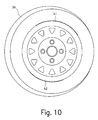
- FIG. 10 shows a camera image of a side view of the motor vehicle wheel from FIG. 1 having two arcs and one rim flange torus recognized therein;
- FIG. 11 shows a camera image of a side view of the motor vehicle wheel from FIG. 1 having one rectangle marked therein.
- FIG. 1 shows a test stand 10 and a motor vehicle 12 whose chassis is to be measured on the test stand.
- Four measuring instruments are arranged in stationary positions on test stand 10 , three measuring instruments 14 , 16 , 18 of these being shown here, while the fourth measuring instrument is concealed by motor vehicle 12 .
- Measuring instruments 14 , 16 , 18 each include a base plate 30 and two cameras 32 , 34 aimed at different angles at particular wheel 36 of motor vehicle 12 .
- measuring instruments 14 , 16 , 18 are fixedly mounted on test stand 10 , the angular positions of the measuring instruments relative to one another and their distances during assembly being defined and then remaining unchanged.
- FIG. 2 shows a test stand 20 with motor vehicle 12 , again showing three measuring instruments 24 , 26 , 28 , while the fourth measuring instrument is concealed by motor vehicle 12 .
- measuring instruments 24 , 26 , 28 again have a base plate 40 and two cameras 42 , 44 , which are aimed at a particular wheel 36 at different angles.
- Reference system measuring heads 50 , 52 , 54 are provided on base plates 40 , 46 , 48 of measuring instruments 24 , 26 , 28 and allow optical measurement of the relative angular positions and distances of measuring instruments 24 , 26 , 28 (and of the measuring instrument concealed by motor vehicle 12 ).
- Each reference system measuring head e.g., reference system measuring head 50 , therefore has two transmit/receive units 56 , 58 , which are aimed at reference system measuring head 52 on the opposite side in the longitudinal direction of vehicle 12 or at reference system measuring head 54 on the opposite side across vehicle 12 .
- an approximate adjustment of measuring instruments 24 , 26 , 28 is sufficient, and an accurate determination of the positions and distances of measuring instruments 24 , 26 , 28 relative to one another may be measured continuously and also readjusted.
- Calibration of the stereo measurement system includes calibration of the “internal camera parameters” and calibration of the installation situation of measuring instruments 24 , 26 , 28 .
- “Internal parameters” refer to all parameters that are camera-specific, i.e., defined by the camera setup. Internal parameters are defined by the installation position of the optical sensor, the lens, and its installation position, the aperture setting and the focus setting. In the case of zoom lenses, the set focal distance is also decisive. The internal parameters may be regarded as constant as long as no mechanical change is made in the camera or no change is made in the lens setting. The parameters are determined with the help of objects that are completely known.
- the calibration is preferably using a 3D object, e.g., an arrangement of planar tangents in various spatial positions that is provided with a sufficiently large number of noticeable points.
- the quality of the illumination is checked on the basis of the available measurement images. They are checked for whether there is adequate segmentability, i.e., for the quality of the shadow border contrast. If the segmentability is inadequate, the illumination is readjusted.
- results of measurement of the reference system include the position of individual measuring instruments relative to one another, including distance, and the position of individual measuring instruments relative to the vertical.
- the distance measurement is performed via the angle measurement of two light emitting diodes (LEDs) with known spacing.
- FIG. 3 shows a schematic flow chart for determining the spatial position of a wheel rim relative to a measuring instrument. It is assumed here that the aforementioned measurements of the reference system and calibration of the measuring instruments are concluded.
- the measurement is started in step 60 .
- the measurements of individual measuring instruments 14 , 16 , 18 or 24 , 26 , 28 are performed in step 62 , and the measurement results are input into a computer (not shown) in steps 64 , 66 .
- the computer determines the transformation matrix from the results of the reference system measurement (BM results), i.e., from the results of the reference system measurement.
- the results of the measuring instruments (MK) are transformed parallel to the axes of the computer coordinate system (RKS axes), a coordinate system of the measuring instruments being arbitrarily defined as the computer coordinate system.
- step 72 the vectors are then shifted, i.e., converted, into the coordinate system of the computer via the offset angles and distances, with the individual transformed result vectors of the stereo measurement being shifted to a common computer coordinate system.
- step 74 the computer determines the wheel position values in space, i.e., in particular the individual toe angles of the front wheels, the total toe angle of the front wheels, the so-called geometric travel axis and the like, as is customary with traditional chassis measuring devices.
- the position of the result vectors relative to one another is analyzed in the computer coordinate system, and the corresponding chassis measured values are calculated from these results.
- step 76 the results for the wheel position values, namely the camber, toe and angle values derived from the toe are transferred to a display device and/or stored for further use.
- FIG. 4 shows a flow chart for determining the spatial position of a wheel rim relative to a measuring instrument in a measuring instrument in somewhat greater detail.
- step 80 a start signal for the measurement is given.
- the image recording is then started in step 82 , and at least one image of wheel rim 36 is recorded, whereupon a check is performed first in step 84 to determine whether the illumination is sufficient for the measurement and the illumination is readjusted, if necessary.
- the readjustment may include greater or lesser brightness of the light for the illumination, the goal being to obtain the greatest possible contrast for the part of the rim and/or the rim flange observed by the cameras.
- the cameras positioned on the right and left with respect to the wheel axis are active (step 86 ) and their function is to check on the illumination situation as well as to record stereo images of wheel rim 36 after adjustment of the illumination is concluded.
- Segmentation of the rims is performed in step 88 .
- point-shaped or dash-shaped geometric details e.g., the valve and its angular position, or toroidal, round or ellipsoidal geometric details, e.g., the rim edge or rim flange, may be defined.
- Segmentation may be subdivided into presegmentation, fine segmentation and subpixel segmentation, and it is performed to measure certain angle ranges of the rim edge and be able to take into account the measured values in ascertaining the plane of the rim edge.
- step 90 After segmentation, a check is performed in step 90 to find whether the segmentation has supplied usable results, i.e., whether at least one usable geometric detail has been ascertained.
- step 92 an area in the image of the camera is defined or selected in step 92 , a renewed segmentation then being performed in step 88 in or on the basis of this area to ascertain a usable geometric detail.
- step 90 If the check in step 90 reveals that at least one usable geometric detail has been ascertained, the real contour of the ascertained geometric detail(s) is determined under model assumptions in step 94 .
- step 96 a check is performed to determine whether the result is unambiguous, i.e., whether there is exactly one or more geometric detail contours. If multiple geometric detail contours have been ascertained, exactly one of these geometric detail contours is selected and the sequence is continued with step 86 . If exactly one geometric detail contour has been ascertained, the sequence is continued with step 104 .
- step 104 optical distortion with respect to the images of the wheel rim is eliminated.
- step 100 the measurement results so far are converted, taking into account the internal camera parameters.
- step 110 For reconstruction of the rim edge (step 110 ), the external camera parameters are taken into account (step 106 ). A first approximation of the plane of the rim edge is then performed and the angle argument is calculated. Model fitting and/or the final determination of the plane of the rim edge is/are performed in step 118 . In step 120 , the result of the calculation, namely the normal vector and the center point of the plane of the rim edge are displayed and/or stored for further calculation. The results thereby obtained are then processed further for calculation of the wheel setting angle values, as described with reference to FIG. 3 in steps 68 to 76 .
- FIG. 5 shows a schematic flow chart for wheel rim runout compensation.
- wheel rim runout compensation in step 122 the results obtained previously in step 120 ( FIG. 4 ) regarding the 3D position of the valve and/or the normal vector and the center point of the plane of the rim edge are taken into account to obtain an “axis of rotation” parameter set, i.e., the true axis of rotation with respect to the normal vector and the valve setting in spherical coordinates.
- Measurement of wheel rotation is required when performing and monitoring rim runout compensation, in determining the steering angle inclination as part of a wheel lock angle measurement and in determining the change in caster angle when adjusting the caster angle.
- a lower measurement accuracy is required for performing and monitoring rim runout compensation. Resolution of wheel rotation to approximately 10 angle minutes is sufficient.
- any rotation of the wheel should be detectable, so tracking and measurement of the valve are sufficient.
- the valve is uniquely positioned on the circumference and may be located with corresponding accuracy.
- wheel rotation is to be determined with an accuracy of at least 2 angle minutes.
- arbitrary rotation of the wheel need not be measurable.
- the 3D position of the valve may be determined.
- non-rotationally symmetrical edges and/or structures in the rim may be measured and tracked, using algorithms corresponding to those used for determining the rim edge.
- FIG. 6 shows a schematic flow chart for calculation of the toe angle and camber angle from the results of step 120 of FIG. 4 and step 124 of FIG. 5 .
- information about the 3D position of the valve and information about the normal vector and the center point of the plane of the rim edge as well as the “axis of rotation” parameter set in step 126 is used to determine the position of the axis of rotation.
- the result of step 126 is transformed in step 128 into the reference coordinate system of the computer, which then calculates the toe angle and camber angle in step 130 .
- the exemplary embodiment shown in FIG. 7 relates to the method variant in which multiple geometric details of the wheel rim are found by the chassis measuring device, and the most suitable geometric detail thereof is selected (step 96 ).
- FIG. 7 shows the camera image of the side view of front left wheel rim 36 , which has been recorded using measuring camera 42 of measuring instrument 24 in step 82 of the method according to FIG. 4 .
- This camera image as well as the following camera images are shown on a display screen, for example.
- FIG. 8 shows a schematic sectional diagram of motor vehicle wheel 36 .
- step 88 Three toruses that were ascertained by segmentation in step 88 according to the method of FIG. 4 , namely rim flange torus T 1 , another torus T 2 having a slightly smaller diameter and a much smaller torus T 3 are discernible on wheel rim 36 . Therefore, checking step 90 yields a positive result and the actual contours of these three toruses T 1 , T 2 and T 3 are determined in step 94 .
- checking step 96 yields a negative result because it is not clear which of three toruses T 1 , T 2 and T 3 is now the most suitable for determining the spatial position of wheel rim 36 relative to measuring instrument 24 .
- Substantially all three toruses T 1 , T 2 and T 3 are suitable for the method according to example embodiments of the present invention for determining the spatial position of a wheel rim relative to a measuring instrument, but wheel rim flange torus T 1 is preferred because the spatial position of wheel rim 36 relative to measuring instrument 24 is then determinable with the greatest accuracy.
- the chassis measuring device ascertains multiple toruses, namely in this case toruses T 1 , T 2 and T 3 , the one that is most suitable for further processing is to be selected for the further method.
- step 98 rim flange torus T 1 is selected for the further method by a user or by a computer (not shown) and after again running through method steps 86 , 88 , 90 , 94 and 96 , the spatial position of wheel rim 36 relative to measuring instrument 24 is now determined by following method steps 100 , 104 , 106 , 110 , 118 , 120 .
- the exemplary embodiments according to FIGS. 9 , 10 , and 11 relate to the method variants in which no suitable geometric detail of the rim is initially detected in step 90 and in which the chassis measuring device is provided with assistance by selection of a partial area (step 92 ), so that it is able to ascertain a suitable geometric detail and use it for the further method.
- FIG. 9 shows a camera image of a side view of motor vehicle wheel 36 having three equidistant points P 1 , P 2 and P 3 marked in it.
- Points P 1 , P 2 and P 3 are equidistant on rim flange torus T 1 .
- the chassis measuring device has not been able to ascertain a geometric detail of the rim, in particular no torus on wheel rim 36 , e.g., due to poor visibility or contrast conditions in the segmentation according to step 88 .
- rim flange torus T 1 three equidistant points P 1 , P 2 and P 3 on rim flange torus T 1 are marked by a user in step 92 , for example, and the chassis measuring device may then ascertain rim flange torus T 1 on the basis of these three equidistant points P 1 , P 2 and P 3 in a renewed segmentation in step 88 and, based on that, perform the further method to determine the spatial position of the wheel rim relative to the measuring instrument, as shown in FIG. 4 .
- FIG. 10 shows a camera image of a side view of motor vehicle wheel 36 having two arc sections b 1 and b 2 of a rim flange torus T 1 recognized therein.
- arc segments b 1 and b 2 are identified as being situated on a common torus T 1 by a user, for example, with the help of a keyboard or a mouse in step 92 , so that the chassis measuring device is able to assemble or ascertain rim flange torus T 1 in renewed segmentation in step 88 from arc segments b 1 and b 2 and may use this rim flange torus T 1 as the basis for the further method for determining the spatial position of the wheel rim relative to the measuring instrument (steps 104 , etc.).
- FIG. 11 shows a camera image of a side view of motor vehicle wheel 36 having a rectangle R marked in it.
- FIG. 11 illustrates the same case as FIG. 9 , namely when the chassis measuring device has not been able to ascertain any geometric detail, in particular a torus on wheel rim 36 in segmentation in step 88 , e.g., due to poor visibility or contrast conditions.
- a rectangle R is drawn around internal torus T 3 (see FIG. 7 ) by a user in step 92 to indicate to the chassis measuring device that a geometric detail is situated in this area, so that the chassis measuring device is able to investigate the area of rectangle R of wheel rim 36 in greater detail during subsequent renewed segmentation in step 88 and is able to ascertain torus T 3 and may use this torus T 3 as a basis for the further method for determination of the spatial position of the wheel rim relative to the measuring instrument (steps 104 , etc.).
Abstract
Description
- 10, 20 test stand
- 12 motor vehicle
- 14, 16, 18 measuring instruments
- 24, 26, 28 measuring instruments
- 32, 34, 42, 44 measuring cameras
- 36 wheel rims, wheels
- 30, 40, 46, 48 base plates
- 50, 52, 54 reference system measuring heads
- 56, 58 transmit/receive units
- T1 rim flange torus
- T2, T3 toruses
- P1, P2, P3 equidistant points
- b1, b2 arc segments
- R rectangle
Claims (23)
Applications Claiming Priority (4)
| Application Number | Priority Date | Filing Date | Title |
|---|---|---|---|
| DE102006042308A DE102006042308A1 (en) | 2006-09-08 | 2006-09-08 | Method for finding a geometry detail for determining the spatial position of a wheel rim to a measuring device and method and apparatus for determining the spatial position of a wheel rim to a measuring device |
| DE102006042308 | 2006-09-08 | ||
| DE102006042308.9 | 2006-09-08 | ||
| PCT/EP2007/058853 WO2008028831A1 (en) | 2006-09-08 | 2007-08-27 | Method for locating a geometric detail for the determination of the spatial position of a wheel rim with respect to a measuring device and method and device for determining the spatial position of a wheel rim with respect to a measuring device |
Publications (2)
| Publication Number | Publication Date |
|---|---|
| US20100037473A1 US20100037473A1 (en) | 2010-02-18 |
| US7877883B2 true US7877883B2 (en) | 2011-02-01 |
Family
ID=38846836
Family Applications (1)
| Application Number | Title | Priority Date | Filing Date |
|---|---|---|---|
| US12/304,165 Expired - Fee Related US7877883B2 (en) | 2006-09-08 | 2007-08-27 | Method for locating a geometric detail for determining the spatial position of a wheel rim relative to a measuring instrument and method and device for determining the spatial position of a wheel rim with respect to a measuring instrument |
Country Status (4)
| Country | Link |
|---|---|
| US (1) | US7877883B2 (en) |
| EP (1) | EP2064517B1 (en) |
| DE (1) | DE102006042308A1 (en) |
| WO (1) | WO2008028831A1 (en) |
Cited By (7)
| Publication number | Priority date | Publication date | Assignee | Title |
|---|---|---|---|---|
| US20090216484A1 (en) * | 2006-09-06 | 2009-08-27 | Stefan Schommer | Method for the relative positioning of an object to be measured and of a motor vehicle to a measuring device, and measuring device and a device for measuring a chassis |
| US20090301181A1 (en) * | 2006-09-06 | 2009-12-10 | Stefan Schommer | Method for measuring the chassis of a motor vehicle, device for measuring a chassis and motor vehicle test line |
| US20100165332A1 (en) * | 2005-09-28 | 2010-07-01 | Hunter Engineering Company | Method and Apparatus For Vehicle Service System Optical Target Assembly |
| US20110185584A1 (en) * | 2007-05-21 | 2011-08-04 | Snap-On Incorporated | Method and apparatus for wheel alignment |
| US20110265337A1 (en) * | 2008-09-12 | 2011-11-03 | Guenter Nobis | Unit of at least two target arrangements for optically measuring an axle and device for optically measuring an axle |
| US20130194446A1 (en) * | 2010-05-05 | 2013-08-01 | Piero Cerruti | System and related method for determining vehicle wheel alignment |
| US9665793B2 (en) | 2013-03-15 | 2017-05-30 | Hunter Engineering Company | Method for determining parameters of a rotating object within a projected pattern |
Families Citing this family (7)
| Publication number | Priority date | Publication date | Assignee | Title |
|---|---|---|---|---|
| DE102005063051A1 (en) * | 2005-12-29 | 2007-07-05 | Robert Bosch Gmbh | Motor vehicle`s e.g. car, chassis measuring method, involves disposing coordinate system for image recording device e.g. camera, and/or measuring unit to determine chassis data of evaluation unit independent of reference objects |
| CN102042806B (en) * | 2010-10-25 | 2012-03-28 | 吉林大学 | Machine vision-based spatial position detection system for automobile wheel planes and rims |
| US9785610B1 (en) * | 2011-11-15 | 2017-10-10 | Hunter Engineering Company | Visual display of vehicle wheel assembly for vehicle wheel service system |
| ITMI20121129A1 (en) * | 2012-06-27 | 2013-12-28 | Vamag Srl | SYSTEM AND METHOD OF MEASUREMENT OF THE CORNERS OF THE WHEELS OF A VEHICLE, BY MEANS OF THREE-DIMENSIONAL TARGETS. |
| AT512762B1 (en) * | 2013-08-01 | 2015-01-15 | Avl List Gmbh | Method and arrangement for driving dynamics assessment |
| DE102013219462A1 (en) * | 2013-09-26 | 2015-03-26 | Robert Bosch Gmbh | Suspension measurement in ambient light |
| DE102022201709A1 (en) | 2022-02-18 | 2023-01-19 | Zf Friedrichshafen Ag | Method for indicating a position of a tire valve of a vehicle tire |
Citations (14)
| Publication number | Priority date | Publication date | Assignee | Title |
|---|---|---|---|---|
| US5488472A (en) * | 1995-01-10 | 1996-01-30 | Hunter Engineering Company | Apparatus for determining vehicle wheel alignment positions and orientations |
| EP0895056A2 (en) | 1997-08-01 | 1999-02-03 | CORGHI S.p.A. | Method and device for regulating the attitude of a motor vehicle. |
| US6323776B1 (en) | 1999-12-21 | 2001-11-27 | Snap-On Technologies, Inc. | Method and apparatus of automatically identifying faults in a machine vision measuring system |
| US20020189115A1 (en) * | 2001-06-15 | 2002-12-19 | Jackson David A. | Self-calibrating position determination system |
| US6526665B2 (en) * | 2000-04-25 | 2003-03-04 | Snap-On Technologies, Inc. | Glint-resistant position determination system |
| US20030055535A1 (en) * | 2001-09-17 | 2003-03-20 | Hunter Engineering Company | Voice interface for vehicle wheel alignment system |
| US20040128844A1 (en) * | 2002-12-18 | 2004-07-08 | Robb Michael J. | Gradient calculating camera board |
| US6842238B2 (en) * | 2002-02-04 | 2005-01-11 | Corghi S.P.A. | Device for measuring the parameters of a vehicle characteristic attitude |
| DE102004013441A1 (en) | 2004-03-18 | 2005-10-13 | Beissbarth Gmbh | Measuring method and measuring device for determining the spatial position of a wheel rim and wheel alignment device |
| WO2006074026A1 (en) | 2004-12-30 | 2006-07-13 | Snap-On Incorporated | Non-contact vehicle measurement method and system |
| US20060274303A1 (en) * | 2005-05-13 | 2006-12-07 | Jackson David A | Wheel aligner measurement module attachment system |
| US20080086900A1 (en) * | 2006-07-18 | 2008-04-17 | Snap-On Incorporated | Vehicle wheel alignment system and methodology |
| US20080289202A1 (en) * | 2007-05-21 | 2008-11-27 | Kassouf Thomas L | Method and apparatus for wheel alignment |
| US20100149526A1 (en) * | 2007-07-27 | 2010-06-17 | Snap-On Incorporated | Fault tolerant wheel alignment head and system |
Family Cites Families (2)
| Publication number | Priority date | Publication date | Assignee | Title |
|---|---|---|---|---|
| DE10033366B4 (en) * | 2000-07-08 | 2007-10-04 | Festo Ag & Co. | Method and detection device for detecting parameters on mechanical devices |
| DE102005022565A1 (en) * | 2005-05-17 | 2006-11-23 | Beissbarth Gmbh | Automatic exposure system for a non-contact automotive service device |
-
2006
- 2006-09-08 DE DE102006042308A patent/DE102006042308A1/en not_active Withdrawn
-
2007
- 2007-08-27 US US12/304,165 patent/US7877883B2/en not_active Expired - Fee Related
- 2007-08-27 EP EP07802894A patent/EP2064517B1/en not_active Not-in-force
- 2007-08-27 WO PCT/EP2007/058853 patent/WO2008028831A1/en active Application Filing
Patent Citations (16)
| Publication number | Priority date | Publication date | Assignee | Title |
|---|---|---|---|---|
| US5488472A (en) * | 1995-01-10 | 1996-01-30 | Hunter Engineering Company | Apparatus for determining vehicle wheel alignment positions and orientations |
| EP0895056A2 (en) | 1997-08-01 | 1999-02-03 | CORGHI S.p.A. | Method and device for regulating the attitude of a motor vehicle. |
| US6323776B1 (en) | 1999-12-21 | 2001-11-27 | Snap-On Technologies, Inc. | Method and apparatus of automatically identifying faults in a machine vision measuring system |
| US6526665B2 (en) * | 2000-04-25 | 2003-03-04 | Snap-On Technologies, Inc. | Glint-resistant position determination system |
| US20020189115A1 (en) * | 2001-06-15 | 2002-12-19 | Jackson David A. | Self-calibrating position determination system |
| US20030055535A1 (en) * | 2001-09-17 | 2003-03-20 | Hunter Engineering Company | Voice interface for vehicle wheel alignment system |
| US6842238B2 (en) * | 2002-02-04 | 2005-01-11 | Corghi S.P.A. | Device for measuring the parameters of a vehicle characteristic attitude |
| US20040128844A1 (en) * | 2002-12-18 | 2004-07-08 | Robb Michael J. | Gradient calculating camera board |
| DE102004013441A1 (en) | 2004-03-18 | 2005-10-13 | Beissbarth Gmbh | Measuring method and measuring device for determining the spatial position of a wheel rim and wheel alignment device |
| US20070283582A1 (en) | 2004-03-18 | 2007-12-13 | Karin Donner | Measuring Method and Measuring Unit for Determining the Spatial Position of a Wheel Rim as Well as a Wheel Alignment Measuring System |
| WO2006074026A1 (en) | 2004-12-30 | 2006-07-13 | Snap-On Incorporated | Non-contact vehicle measurement method and system |
| US20060274303A1 (en) * | 2005-05-13 | 2006-12-07 | Jackson David A | Wheel aligner measurement module attachment system |
| US20080086900A1 (en) * | 2006-07-18 | 2008-04-17 | Snap-On Incorporated | Vehicle wheel alignment system and methodology |
| US7458165B2 (en) * | 2006-07-18 | 2008-12-02 | Snap-On Incorporated | Vehicle wheel alignment system and methodology |
| US20080289202A1 (en) * | 2007-05-21 | 2008-11-27 | Kassouf Thomas L | Method and apparatus for wheel alignment |
| US20100149526A1 (en) * | 2007-07-27 | 2010-06-17 | Snap-On Incorporated | Fault tolerant wheel alignment head and system |
Non-Patent Citations (1)
| Title |
|---|
| International Search Report, PCT/EP2007/058853 dated Jan. 21, 2008. |
Cited By (15)
| Publication number | Priority date | Publication date | Assignee | Title |
|---|---|---|---|---|
| US20100165332A1 (en) * | 2005-09-28 | 2010-07-01 | Hunter Engineering Company | Method and Apparatus For Vehicle Service System Optical Target Assembly |
| US7930834B2 (en) * | 2005-09-28 | 2011-04-26 | Hunter Engineering Company | Method and apparatus for vehicle service system optical target assembly |
| US8096057B2 (en) * | 2006-09-06 | 2012-01-17 | Robert Bosch Gmbh | Method for the relative positioning of an object to be measured and of a motor vehicle to a measuring device, and measuring device and a device for measuring a chassis |
| US20090301181A1 (en) * | 2006-09-06 | 2009-12-10 | Stefan Schommer | Method for measuring the chassis of a motor vehicle, device for measuring a chassis and motor vehicle test line |
| US20090216484A1 (en) * | 2006-09-06 | 2009-08-27 | Stefan Schommer | Method for the relative positioning of an object to be measured and of a motor vehicle to a measuring device, and measuring device and a device for measuring a chassis |
| US8127599B2 (en) * | 2006-09-06 | 2012-03-06 | Robert Bosch Gmbh | Method for measuring the chassis of a motor vehicle, device for measuring a chassis and motor vehicle test line |
| US8401236B2 (en) | 2007-05-21 | 2013-03-19 | Snap-On Incorporated | Method and apparatus for wheel alignment |
| US20110185584A1 (en) * | 2007-05-21 | 2011-08-04 | Snap-On Incorporated | Method and apparatus for wheel alignment |
| US20110302795A1 (en) * | 2008-09-12 | 2011-12-15 | Guenter Nobis | Target system, set of target systems and device for optically aligning an axle |
| US20110265337A1 (en) * | 2008-09-12 | 2011-11-03 | Guenter Nobis | Unit of at least two target arrangements for optically measuring an axle and device for optically measuring an axle |
| US8448342B2 (en) * | 2008-09-12 | 2013-05-28 | Robert Bosch Gmbh | Unit of at least two target arrangements for optically measuring an axle and device for optically measuring an axle |
| US8650766B2 (en) * | 2008-09-12 | 2014-02-18 | Robert Bosch Gmbh | Target system, set of target systems and device for optically aligning an axle |
| US20130194446A1 (en) * | 2010-05-05 | 2013-08-01 | Piero Cerruti | System and related method for determining vehicle wheel alignment |
| US9300864B2 (en) * | 2010-05-05 | 2016-03-29 | Space S.R.L. Con Unico Socio | System and related method for determining vehicle wheel alignment |
| US9665793B2 (en) | 2013-03-15 | 2017-05-30 | Hunter Engineering Company | Method for determining parameters of a rotating object within a projected pattern |
Also Published As
| Publication number | Publication date |
|---|---|
| DE102006042308A1 (en) | 2008-03-27 |
| EP2064517A1 (en) | 2009-06-03 |
| EP2064517B1 (en) | 2013-02-27 |
| US20100037473A1 (en) | 2010-02-18 |
| WO2008028831A1 (en) | 2008-03-13 |
Similar Documents
| Publication | Publication Date | Title |
|---|---|---|
| US7877883B2 (en) | Method for locating a geometric detail for determining the spatial position of a wheel rim relative to a measuring instrument and method and device for determining the spatial position of a wheel rim with respect to a measuring instrument | |
| US7860295B2 (en) | Measuring method and measuring unit for determining the spatial position of a wheel rim as well as a wheel alignment measuring system | |
| JP2936114B2 (en) | Method and apparatus for determining the alignment of wheels of a motor vehicle | |
| AU711728B2 (en) | Method and apparatus for determining the alignment of motor vehicle wheels | |
| JP4617377B2 (en) | Method for determining vehicle wheel position angle using optical measuring device | |
| EP0927335B1 (en) | Calibrating cameras used in alignment of wheels | |
| US8363979B2 (en) | Method for ascertaining the axis of rotation of a vehicle wheel | |
| US20110308309A1 (en) | Method for wheel suspension measurement and a device for measuring the wheel suspension geometry of a vehicle | |
| CA2383989A1 (en) | Method and apparatus for measuring vehicle wheel roll radius | |
| CN103398674A (en) | Non contact wheel alignment sensor and method | |
| KR20070016095A (en) | Measuring Method and Measuring Unit for Determining the Spatial Position of a Wheel Rim, and Chassis Measuring Device | |
| CN113532331B (en) | Non-contact type corner measurement system and method | |
| US8570537B1 (en) | Method for bore chamfer measurement | |
| AU669211C (en) | Method and apparatus for determining the alignment of motor vehicle wheels | |
| US20230154031A1 (en) | Verification method of dynamic virtual image display distance of user interface and system thereof | |
| JPH1137735A (en) | Method for measuring origin of image, and its recording medium |
Legal Events
| Date | Code | Title | Description |
|---|---|---|---|
| AS | Assignment |
Owner name: ROBERT BOSCH GMBH,GERMANY Free format text: ASSIGNMENT OF ASSIGNORS INTEREST;ASSIGNORS:SCHOMMER, STEFAN;BUX, HERMANN;SIGNING DATES FROM 20090127 TO 20090128;REEL/FRAME:022995/0976 Owner name: ROBERT BOSCH GMBH, GERMANY Free format text: ASSIGNMENT OF ASSIGNORS INTEREST;ASSIGNORS:SCHOMMER, STEFAN;BUX, HERMANN;SIGNING DATES FROM 20090127 TO 20090128;REEL/FRAME:022995/0976 |
|
| STCF | Information on status: patent grant |
Free format text: PATENTED CASE |
|
| FPAY | Fee payment |
Year of fee payment: 4 |
|
| MAFP | Maintenance fee payment |
Free format text: PAYMENT OF MAINTENANCE FEE, 8TH YEAR, LARGE ENTITY (ORIGINAL EVENT CODE: M1552) Year of fee payment: 8 |
|
| AS | Assignment |
Owner name: BEISSBARTH GMBH, GERMANY Free format text: ASSIGNMENT OF ASSIGNORS INTEREST;ASSIGNOR:ROBERT BOSCH GMBH;REEL/FRAME:048809/0192 Effective date: 20190322 |
|
| FEPP | Fee payment procedure |
Free format text: ENTITY STATUS SET TO SMALL (ORIGINAL EVENT CODE: SMAL); ENTITY STATUS OF PATENT OWNER: SMALL ENTITY |
|
| FEPP | Fee payment procedure |
Free format text: MAINTENANCE FEE REMINDER MAILED (ORIGINAL EVENT CODE: REM.); ENTITY STATUS OF PATENT OWNER: SMALL ENTITY |
|
| LAPS | Lapse for failure to pay maintenance fees |
Free format text: PATENT EXPIRED FOR FAILURE TO PAY MAINTENANCE FEES (ORIGINAL EVENT CODE: EXP.); ENTITY STATUS OF PATENT OWNER: SMALL ENTITY |
|
| STCH | Information on status: patent discontinuation |
Free format text: PATENT EXPIRED DUE TO NONPAYMENT OF MAINTENANCE FEES UNDER 37 CFR 1.362 |
|
| FP | Lapsed due to failure to pay maintenance fee |
Effective date: 20230201 |