US7879095B2 - Method of inserting, rotating and releasing a spring-loaded artificial disk - Google Patents
Method of inserting, rotating and releasing a spring-loaded artificial disk Download PDFInfo
- Publication number
- US7879095B2 US7879095B2 US10/804,895 US80489504A US7879095B2 US 7879095 B2 US7879095 B2 US 7879095B2 US 80489504 A US80489504 A US 80489504A US 7879095 B2 US7879095 B2 US 7879095B2
- Authority
- US
- United States
- Prior art keywords
- implant
- insert
- intervertebral disk
- disk space
- disk
- Prior art date
- Legal status (The legal status is an assumption and is not a legal conclusion. Google has not performed a legal analysis and makes no representation as to the accuracy of the status listed.)
- Expired - Fee Related
Links
Images


Classifications
-
- A—HUMAN NECESSITIES
- A61—MEDICAL OR VETERINARY SCIENCE; HYGIENE
- A61B—DIAGNOSIS; SURGERY; IDENTIFICATION
- A61B17/00—Surgical instruments, devices or methods, e.g. tourniquets
- A61B17/02—Surgical instruments, devices or methods, e.g. tourniquets for holding wounds open; Tractors
- A61B17/025—Joint distractors
-
- A—HUMAN NECESSITIES
- A61—MEDICAL OR VETERINARY SCIENCE; HYGIENE
- A61F—FILTERS IMPLANTABLE INTO BLOOD VESSELS; PROSTHESES; DEVICES PROVIDING PATENCY TO, OR PREVENTING COLLAPSING OF, TUBULAR STRUCTURES OF THE BODY, e.g. STENTS; ORTHOPAEDIC, NURSING OR CONTRACEPTIVE DEVICES; FOMENTATION; TREATMENT OR PROTECTION OF EYES OR EARS; BANDAGES, DRESSINGS OR ABSORBENT PADS; FIRST-AID KITS
- A61F2/00—Filters implantable into blood vessels; Prostheses, i.e. artificial substitutes or replacements for parts of the body; Appliances for connecting them with the body; Devices providing patency to, or preventing collapsing of, tubular structures of the body, e.g. stents
- A61F2/02—Prostheses implantable into the body
- A61F2/28—Bones
-
- A—HUMAN NECESSITIES
- A61—MEDICAL OR VETERINARY SCIENCE; HYGIENE
- A61F—FILTERS IMPLANTABLE INTO BLOOD VESSELS; PROSTHESES; DEVICES PROVIDING PATENCY TO, OR PREVENTING COLLAPSING OF, TUBULAR STRUCTURES OF THE BODY, e.g. STENTS; ORTHOPAEDIC, NURSING OR CONTRACEPTIVE DEVICES; FOMENTATION; TREATMENT OR PROTECTION OF EYES OR EARS; BANDAGES, DRESSINGS OR ABSORBENT PADS; FIRST-AID KITS
- A61F2/00—Filters implantable into blood vessels; Prostheses, i.e. artificial substitutes or replacements for parts of the body; Appliances for connecting them with the body; Devices providing patency to, or preventing collapsing of, tubular structures of the body, e.g. stents
- A61F2/02—Prostheses implantable into the body
- A61F2/30—Joints
- A61F2/44—Joints for the spine, e.g. vertebrae, spinal discs
- A61F2/442—Intervertebral or spinal discs, e.g. resilient
-
- A—HUMAN NECESSITIES
- A61—MEDICAL OR VETERINARY SCIENCE; HYGIENE
- A61F—FILTERS IMPLANTABLE INTO BLOOD VESSELS; PROSTHESES; DEVICES PROVIDING PATENCY TO, OR PREVENTING COLLAPSING OF, TUBULAR STRUCTURES OF THE BODY, e.g. STENTS; ORTHOPAEDIC, NURSING OR CONTRACEPTIVE DEVICES; FOMENTATION; TREATMENT OR PROTECTION OF EYES OR EARS; BANDAGES, DRESSINGS OR ABSORBENT PADS; FIRST-AID KITS
- A61F2/00—Filters implantable into blood vessels; Prostheses, i.e. artificial substitutes or replacements for parts of the body; Appliances for connecting them with the body; Devices providing patency to, or preventing collapsing of, tubular structures of the body, e.g. stents
- A61F2/02—Prostheses implantable into the body
- A61F2/30—Joints
- A61F2/44—Joints for the spine, e.g. vertebrae, spinal discs
- A61F2/4455—Joints for the spine, e.g. vertebrae, spinal discs for the fusion of spinal bodies, e.g. intervertebral fusion of adjacent spinal bodies, e.g. fusion cages
- A61F2/446—Joints for the spine, e.g. vertebrae, spinal discs for the fusion of spinal bodies, e.g. intervertebral fusion of adjacent spinal bodies, e.g. fusion cages having a circular or elliptical cross-section substantially parallel to the axis of the spine, e.g. cylinders or frustocones
-
- A—HUMAN NECESSITIES
- A61—MEDICAL OR VETERINARY SCIENCE; HYGIENE
- A61F—FILTERS IMPLANTABLE INTO BLOOD VESSELS; PROSTHESES; DEVICES PROVIDING PATENCY TO, OR PREVENTING COLLAPSING OF, TUBULAR STRUCTURES OF THE BODY, e.g. STENTS; ORTHOPAEDIC, NURSING OR CONTRACEPTIVE DEVICES; FOMENTATION; TREATMENT OR PROTECTION OF EYES OR EARS; BANDAGES, DRESSINGS OR ABSORBENT PADS; FIRST-AID KITS
- A61F2/00—Filters implantable into blood vessels; Prostheses, i.e. artificial substitutes or replacements for parts of the body; Appliances for connecting them with the body; Devices providing patency to, or preventing collapsing of, tubular structures of the body, e.g. stents
- A61F2/02—Prostheses implantable into the body
- A61F2/30—Joints
- A61F2/46—Special tools or methods for implanting or extracting artificial joints, accessories, bone grafts or substitutes, or particular adaptations therefor
- A61F2/4603—Special tools or methods for implanting or extracting artificial joints, accessories, bone grafts or substitutes, or particular adaptations therefor for insertion or extraction of endoprosthetic joints or of accessories thereof
- A61F2/4611—Special tools or methods for implanting or extracting artificial joints, accessories, bone grafts or substitutes, or particular adaptations therefor for insertion or extraction of endoprosthetic joints or of accessories thereof of spinal prostheses
-
- A—HUMAN NECESSITIES
- A61—MEDICAL OR VETERINARY SCIENCE; HYGIENE
- A61B—DIAGNOSIS; SURGERY; IDENTIFICATION
- A61B17/00—Surgical instruments, devices or methods, e.g. tourniquets
- A61B17/02—Surgical instruments, devices or methods, e.g. tourniquets for holding wounds open; Tractors
- A61B17/025—Joint distractors
- A61B2017/0256—Joint distractors for the spine
-
- A—HUMAN NECESSITIES
- A61—MEDICAL OR VETERINARY SCIENCE; HYGIENE
- A61F—FILTERS IMPLANTABLE INTO BLOOD VESSELS; PROSTHESES; DEVICES PROVIDING PATENCY TO, OR PREVENTING COLLAPSING OF, TUBULAR STRUCTURES OF THE BODY, e.g. STENTS; ORTHOPAEDIC, NURSING OR CONTRACEPTIVE DEVICES; FOMENTATION; TREATMENT OR PROTECTION OF EYES OR EARS; BANDAGES, DRESSINGS OR ABSORBENT PADS; FIRST-AID KITS
- A61F2/00—Filters implantable into blood vessels; Prostheses, i.e. artificial substitutes or replacements for parts of the body; Appliances for connecting them with the body; Devices providing patency to, or preventing collapsing of, tubular structures of the body, e.g. stents
- A61F2/02—Prostheses implantable into the body
- A61F2/30—Joints
- A61F2/3094—Designing or manufacturing processes
- A61F2/30965—Reinforcing the prosthesis by embedding particles or fibres during moulding or dipping
-
- A—HUMAN NECESSITIES
- A61—MEDICAL OR VETERINARY SCIENCE; HYGIENE
- A61F—FILTERS IMPLANTABLE INTO BLOOD VESSELS; PROSTHESES; DEVICES PROVIDING PATENCY TO, OR PREVENTING COLLAPSING OF, TUBULAR STRUCTURES OF THE BODY, e.g. STENTS; ORTHOPAEDIC, NURSING OR CONTRACEPTIVE DEVICES; FOMENTATION; TREATMENT OR PROTECTION OF EYES OR EARS; BANDAGES, DRESSINGS OR ABSORBENT PADS; FIRST-AID KITS
- A61F2/00—Filters implantable into blood vessels; Prostheses, i.e. artificial substitutes or replacements for parts of the body; Appliances for connecting them with the body; Devices providing patency to, or preventing collapsing of, tubular structures of the body, e.g. stents
- A61F2/02—Prostheses implantable into the body
- A61F2/30—Joints
- A61F2/44—Joints for the spine, e.g. vertebrae, spinal discs
- A61F2/4455—Joints for the spine, e.g. vertebrae, spinal discs for the fusion of spinal bodies, e.g. intervertebral fusion of adjacent spinal bodies, e.g. fusion cages
-
- A—HUMAN NECESSITIES
- A61—MEDICAL OR VETERINARY SCIENCE; HYGIENE
- A61F—FILTERS IMPLANTABLE INTO BLOOD VESSELS; PROSTHESES; DEVICES PROVIDING PATENCY TO, OR PREVENTING COLLAPSING OF, TUBULAR STRUCTURES OF THE BODY, e.g. STENTS; ORTHOPAEDIC, NURSING OR CONTRACEPTIVE DEVICES; FOMENTATION; TREATMENT OR PROTECTION OF EYES OR EARS; BANDAGES, DRESSINGS OR ABSORBENT PADS; FIRST-AID KITS
- A61F2/00—Filters implantable into blood vessels; Prostheses, i.e. artificial substitutes or replacements for parts of the body; Appliances for connecting them with the body; Devices providing patency to, or preventing collapsing of, tubular structures of the body, e.g. stents
- A61F2/02—Prostheses implantable into the body
- A61F2/30—Joints
- A61F2/46—Special tools or methods for implanting or extracting artificial joints, accessories, bone grafts or substitutes, or particular adaptations therefor
- A61F2/4603—Special tools or methods for implanting or extracting artificial joints, accessories, bone grafts or substitutes, or particular adaptations therefor for insertion or extraction of endoprosthetic joints or of accessories thereof
-
- A—HUMAN NECESSITIES
- A61—MEDICAL OR VETERINARY SCIENCE; HYGIENE
- A61F—FILTERS IMPLANTABLE INTO BLOOD VESSELS; PROSTHESES; DEVICES PROVIDING PATENCY TO, OR PREVENTING COLLAPSING OF, TUBULAR STRUCTURES OF THE BODY, e.g. STENTS; ORTHOPAEDIC, NURSING OR CONTRACEPTIVE DEVICES; FOMENTATION; TREATMENT OR PROTECTION OF EYES OR EARS; BANDAGES, DRESSINGS OR ABSORBENT PADS; FIRST-AID KITS
- A61F2/00—Filters implantable into blood vessels; Prostheses, i.e. artificial substitutes or replacements for parts of the body; Appliances for connecting them with the body; Devices providing patency to, or preventing collapsing of, tubular structures of the body, e.g. stents
- A61F2/02—Prostheses implantable into the body
- A61F2/28—Bones
- A61F2002/2825—Femur
-
- A—HUMAN NECESSITIES
- A61—MEDICAL OR VETERINARY SCIENCE; HYGIENE
- A61F—FILTERS IMPLANTABLE INTO BLOOD VESSELS; PROSTHESES; DEVICES PROVIDING PATENCY TO, OR PREVENTING COLLAPSING OF, TUBULAR STRUCTURES OF THE BODY, e.g. STENTS; ORTHOPAEDIC, NURSING OR CONTRACEPTIVE DEVICES; FOMENTATION; TREATMENT OR PROTECTION OF EYES OR EARS; BANDAGES, DRESSINGS OR ABSORBENT PADS; FIRST-AID KITS
- A61F2/00—Filters implantable into blood vessels; Prostheses, i.e. artificial substitutes or replacements for parts of the body; Appliances for connecting them with the body; Devices providing patency to, or preventing collapsing of, tubular structures of the body, e.g. stents
- A61F2/02—Prostheses implantable into the body
- A61F2/28—Bones
- A61F2002/2835—Bone graft implants for filling a bony defect or an endoprosthesis cavity, e.g. by synthetic material or biological material
- A61F2002/2839—Bone plugs or bone graft dowels
-
- A—HUMAN NECESSITIES
- A61—MEDICAL OR VETERINARY SCIENCE; HYGIENE
- A61F—FILTERS IMPLANTABLE INTO BLOOD VESSELS; PROSTHESES; DEVICES PROVIDING PATENCY TO, OR PREVENTING COLLAPSING OF, TUBULAR STRUCTURES OF THE BODY, e.g. STENTS; ORTHOPAEDIC, NURSING OR CONTRACEPTIVE DEVICES; FOMENTATION; TREATMENT OR PROTECTION OF EYES OR EARS; BANDAGES, DRESSINGS OR ABSORBENT PADS; FIRST-AID KITS
- A61F2/00—Filters implantable into blood vessels; Prostheses, i.e. artificial substitutes or replacements for parts of the body; Appliances for connecting them with the body; Devices providing patency to, or preventing collapsing of, tubular structures of the body, e.g. stents
- A61F2/02—Prostheses implantable into the body
- A61F2/30—Joints
- A61F2002/30001—Additional features of subject-matter classified in A61F2/28, A61F2/30 and subgroups thereof
- A61F2002/30003—Material related properties of the prosthesis or of a coating on the prosthesis
- A61F2002/30004—Material related properties of the prosthesis or of a coating on the prosthesis the prosthesis being made from materials having different values of a given property at different locations within the same prosthesis
- A61F2002/30057—Material related properties of the prosthesis or of a coating on the prosthesis the prosthesis being made from materials having different values of a given property at different locations within the same prosthesis made from both cortical and cancellous adjacent parts
-
- A—HUMAN NECESSITIES
- A61—MEDICAL OR VETERINARY SCIENCE; HYGIENE
- A61F—FILTERS IMPLANTABLE INTO BLOOD VESSELS; PROSTHESES; DEVICES PROVIDING PATENCY TO, OR PREVENTING COLLAPSING OF, TUBULAR STRUCTURES OF THE BODY, e.g. STENTS; ORTHOPAEDIC, NURSING OR CONTRACEPTIVE DEVICES; FOMENTATION; TREATMENT OR PROTECTION OF EYES OR EARS; BANDAGES, DRESSINGS OR ABSORBENT PADS; FIRST-AID KITS
- A61F2/00—Filters implantable into blood vessels; Prostheses, i.e. artificial substitutes or replacements for parts of the body; Appliances for connecting them with the body; Devices providing patency to, or preventing collapsing of, tubular structures of the body, e.g. stents
- A61F2/02—Prostheses implantable into the body
- A61F2/30—Joints
- A61F2002/30001—Additional features of subject-matter classified in A61F2/28, A61F2/30 and subgroups thereof
- A61F2002/30003—Material related properties of the prosthesis or of a coating on the prosthesis
- A61F2002/3006—Properties of materials and coating materials
- A61F2002/30069—Properties of materials and coating materials elastomeric
-
- A—HUMAN NECESSITIES
- A61—MEDICAL OR VETERINARY SCIENCE; HYGIENE
- A61F—FILTERS IMPLANTABLE INTO BLOOD VESSELS; PROSTHESES; DEVICES PROVIDING PATENCY TO, OR PREVENTING COLLAPSING OF, TUBULAR STRUCTURES OF THE BODY, e.g. STENTS; ORTHOPAEDIC, NURSING OR CONTRACEPTIVE DEVICES; FOMENTATION; TREATMENT OR PROTECTION OF EYES OR EARS; BANDAGES, DRESSINGS OR ABSORBENT PADS; FIRST-AID KITS
- A61F2/00—Filters implantable into blood vessels; Prostheses, i.e. artificial substitutes or replacements for parts of the body; Appliances for connecting them with the body; Devices providing patency to, or preventing collapsing of, tubular structures of the body, e.g. stents
- A61F2/02—Prostheses implantable into the body
- A61F2/30—Joints
- A61F2002/30001—Additional features of subject-matter classified in A61F2/28, A61F2/30 and subgroups thereof
- A61F2002/30108—Shapes
- A61F2002/3011—Cross-sections or two-dimensional shapes
- A61F2002/30138—Convex polygonal shapes
- A61F2002/30153—Convex polygonal shapes rectangular
-
- A—HUMAN NECESSITIES
- A61—MEDICAL OR VETERINARY SCIENCE; HYGIENE
- A61F—FILTERS IMPLANTABLE INTO BLOOD VESSELS; PROSTHESES; DEVICES PROVIDING PATENCY TO, OR PREVENTING COLLAPSING OF, TUBULAR STRUCTURES OF THE BODY, e.g. STENTS; ORTHOPAEDIC, NURSING OR CONTRACEPTIVE DEVICES; FOMENTATION; TREATMENT OR PROTECTION OF EYES OR EARS; BANDAGES, DRESSINGS OR ABSORBENT PADS; FIRST-AID KITS
- A61F2/00—Filters implantable into blood vessels; Prostheses, i.e. artificial substitutes or replacements for parts of the body; Appliances for connecting them with the body; Devices providing patency to, or preventing collapsing of, tubular structures of the body, e.g. stents
- A61F2/02—Prostheses implantable into the body
- A61F2/30—Joints
- A61F2002/30001—Additional features of subject-matter classified in A61F2/28, A61F2/30 and subgroups thereof
- A61F2002/30108—Shapes
- A61F2002/3011—Cross-sections or two-dimensional shapes
- A61F2002/30159—Concave polygonal shapes
- A61F2002/30169—Pi-shaped
-
- A—HUMAN NECESSITIES
- A61—MEDICAL OR VETERINARY SCIENCE; HYGIENE
- A61F—FILTERS IMPLANTABLE INTO BLOOD VESSELS; PROSTHESES; DEVICES PROVIDING PATENCY TO, OR PREVENTING COLLAPSING OF, TUBULAR STRUCTURES OF THE BODY, e.g. STENTS; ORTHOPAEDIC, NURSING OR CONTRACEPTIVE DEVICES; FOMENTATION; TREATMENT OR PROTECTION OF EYES OR EARS; BANDAGES, DRESSINGS OR ABSORBENT PADS; FIRST-AID KITS
- A61F2/00—Filters implantable into blood vessels; Prostheses, i.e. artificial substitutes or replacements for parts of the body; Appliances for connecting them with the body; Devices providing patency to, or preventing collapsing of, tubular structures of the body, e.g. stents
- A61F2/02—Prostheses implantable into the body
- A61F2/30—Joints
- A61F2002/30001—Additional features of subject-matter classified in A61F2/28, A61F2/30 and subgroups thereof
- A61F2002/30108—Shapes
- A61F2002/30199—Three-dimensional shapes
- A61F2002/30205—Three-dimensional shapes conical
- A61F2002/30214—Three-dimensional shapes conical having tapered sections of different conicities
-
- A—HUMAN NECESSITIES
- A61—MEDICAL OR VETERINARY SCIENCE; HYGIENE
- A61F—FILTERS IMPLANTABLE INTO BLOOD VESSELS; PROSTHESES; DEVICES PROVIDING PATENCY TO, OR PREVENTING COLLAPSING OF, TUBULAR STRUCTURES OF THE BODY, e.g. STENTS; ORTHOPAEDIC, NURSING OR CONTRACEPTIVE DEVICES; FOMENTATION; TREATMENT OR PROTECTION OF EYES OR EARS; BANDAGES, DRESSINGS OR ABSORBENT PADS; FIRST-AID KITS
- A61F2/00—Filters implantable into blood vessels; Prostheses, i.e. artificial substitutes or replacements for parts of the body; Appliances for connecting them with the body; Devices providing patency to, or preventing collapsing of, tubular structures of the body, e.g. stents
- A61F2/02—Prostheses implantable into the body
- A61F2/30—Joints
- A61F2002/30001—Additional features of subject-matter classified in A61F2/28, A61F2/30 and subgroups thereof
- A61F2002/30108—Shapes
- A61F2002/30199—Three-dimensional shapes
- A61F2002/30224—Three-dimensional shapes cylindrical
-
- A—HUMAN NECESSITIES
- A61—MEDICAL OR VETERINARY SCIENCE; HYGIENE
- A61F—FILTERS IMPLANTABLE INTO BLOOD VESSELS; PROSTHESES; DEVICES PROVIDING PATENCY TO, OR PREVENTING COLLAPSING OF, TUBULAR STRUCTURES OF THE BODY, e.g. STENTS; ORTHOPAEDIC, NURSING OR CONTRACEPTIVE DEVICES; FOMENTATION; TREATMENT OR PROTECTION OF EYES OR EARS; BANDAGES, DRESSINGS OR ABSORBENT PADS; FIRST-AID KITS
- A61F2/00—Filters implantable into blood vessels; Prostheses, i.e. artificial substitutes or replacements for parts of the body; Appliances for connecting them with the body; Devices providing patency to, or preventing collapsing of, tubular structures of the body, e.g. stents
- A61F2/02—Prostheses implantable into the body
- A61F2/30—Joints
- A61F2002/30001—Additional features of subject-matter classified in A61F2/28, A61F2/30 and subgroups thereof
- A61F2002/30108—Shapes
- A61F2002/30199—Three-dimensional shapes
- A61F2002/30252—Three-dimensional shapes quadric-shaped
- A61F2002/30253—Three-dimensional shapes quadric-shaped ellipsoidal or ovoid
-
- A—HUMAN NECESSITIES
- A61—MEDICAL OR VETERINARY SCIENCE; HYGIENE
- A61F—FILTERS IMPLANTABLE INTO BLOOD VESSELS; PROSTHESES; DEVICES PROVIDING PATENCY TO, OR PREVENTING COLLAPSING OF, TUBULAR STRUCTURES OF THE BODY, e.g. STENTS; ORTHOPAEDIC, NURSING OR CONTRACEPTIVE DEVICES; FOMENTATION; TREATMENT OR PROTECTION OF EYES OR EARS; BANDAGES, DRESSINGS OR ABSORBENT PADS; FIRST-AID KITS
- A61F2/00—Filters implantable into blood vessels; Prostheses, i.e. artificial substitutes or replacements for parts of the body; Appliances for connecting them with the body; Devices providing patency to, or preventing collapsing of, tubular structures of the body, e.g. stents
- A61F2/02—Prostheses implantable into the body
- A61F2/30—Joints
- A61F2002/30001—Additional features of subject-matter classified in A61F2/28, A61F2/30 and subgroups thereof
- A61F2002/30108—Shapes
- A61F2002/30199—Three-dimensional shapes
- A61F2002/30286—Three-dimensional shapes barrel-shaped
-
- A—HUMAN NECESSITIES
- A61—MEDICAL OR VETERINARY SCIENCE; HYGIENE
- A61F—FILTERS IMPLANTABLE INTO BLOOD VESSELS; PROSTHESES; DEVICES PROVIDING PATENCY TO, OR PREVENTING COLLAPSING OF, TUBULAR STRUCTURES OF THE BODY, e.g. STENTS; ORTHOPAEDIC, NURSING OR CONTRACEPTIVE DEVICES; FOMENTATION; TREATMENT OR PROTECTION OF EYES OR EARS; BANDAGES, DRESSINGS OR ABSORBENT PADS; FIRST-AID KITS
- A61F2/00—Filters implantable into blood vessels; Prostheses, i.e. artificial substitutes or replacements for parts of the body; Appliances for connecting them with the body; Devices providing patency to, or preventing collapsing of, tubular structures of the body, e.g. stents
- A61F2/02—Prostheses implantable into the body
- A61F2/30—Joints
- A61F2002/30001—Additional features of subject-matter classified in A61F2/28, A61F2/30 and subgroups thereof
- A61F2002/30316—The prosthesis having different structural features at different locations within the same prosthesis; Connections between prosthetic parts; Special structural features of bone or joint prostheses not otherwise provided for
- A61F2002/30329—Connections or couplings between prosthetic parts, e.g. between modular parts; Connecting elements
- A61F2002/30331—Connections or couplings between prosthetic parts, e.g. between modular parts; Connecting elements made by longitudinally pushing a protrusion into a complementarily-shaped recess, e.g. held by friction fit
- A61F2002/30362—Connections or couplings between prosthetic parts, e.g. between modular parts; Connecting elements made by longitudinally pushing a protrusion into a complementarily-shaped recess, e.g. held by friction fit with possibility of relative movement between the protrusion and the recess
- A61F2002/3037—Translation along the common longitudinal axis, e.g. piston
-
- A—HUMAN NECESSITIES
- A61—MEDICAL OR VETERINARY SCIENCE; HYGIENE
- A61F—FILTERS IMPLANTABLE INTO BLOOD VESSELS; PROSTHESES; DEVICES PROVIDING PATENCY TO, OR PREVENTING COLLAPSING OF, TUBULAR STRUCTURES OF THE BODY, e.g. STENTS; ORTHOPAEDIC, NURSING OR CONTRACEPTIVE DEVICES; FOMENTATION; TREATMENT OR PROTECTION OF EYES OR EARS; BANDAGES, DRESSINGS OR ABSORBENT PADS; FIRST-AID KITS
- A61F2/00—Filters implantable into blood vessels; Prostheses, i.e. artificial substitutes or replacements for parts of the body; Appliances for connecting them with the body; Devices providing patency to, or preventing collapsing of, tubular structures of the body, e.g. stents
- A61F2/02—Prostheses implantable into the body
- A61F2/30—Joints
- A61F2002/30001—Additional features of subject-matter classified in A61F2/28, A61F2/30 and subgroups thereof
- A61F2002/30316—The prosthesis having different structural features at different locations within the same prosthesis; Connections between prosthetic parts; Special structural features of bone or joint prostheses not otherwise provided for
- A61F2002/30329—Connections or couplings between prosthetic parts, e.g. between modular parts; Connecting elements
- A61F2002/30383—Connections or couplings between prosthetic parts, e.g. between modular parts; Connecting elements made by laterally inserting a protrusion, e.g. a rib into a complementarily-shaped groove
- A61F2002/3039—Connections or couplings between prosthetic parts, e.g. between modular parts; Connecting elements made by laterally inserting a protrusion, e.g. a rib into a complementarily-shaped groove with possibility of relative movement of the rib within the groove
- A61F2002/30398—Sliding
-
- A—HUMAN NECESSITIES
- A61—MEDICAL OR VETERINARY SCIENCE; HYGIENE
- A61F—FILTERS IMPLANTABLE INTO BLOOD VESSELS; PROSTHESES; DEVICES PROVIDING PATENCY TO, OR PREVENTING COLLAPSING OF, TUBULAR STRUCTURES OF THE BODY, e.g. STENTS; ORTHOPAEDIC, NURSING OR CONTRACEPTIVE DEVICES; FOMENTATION; TREATMENT OR PROTECTION OF EYES OR EARS; BANDAGES, DRESSINGS OR ABSORBENT PADS; FIRST-AID KITS
- A61F2/00—Filters implantable into blood vessels; Prostheses, i.e. artificial substitutes or replacements for parts of the body; Appliances for connecting them with the body; Devices providing patency to, or preventing collapsing of, tubular structures of the body, e.g. stents
- A61F2/02—Prostheses implantable into the body
- A61F2/30—Joints
- A61F2002/30001—Additional features of subject-matter classified in A61F2/28, A61F2/30 and subgroups thereof
- A61F2002/30316—The prosthesis having different structural features at different locations within the same prosthesis; Connections between prosthetic parts; Special structural features of bone or joint prostheses not otherwise provided for
- A61F2002/30329—Connections or couplings between prosthetic parts, e.g. between modular parts; Connecting elements
- A61F2002/30405—Connections or couplings between prosthetic parts, e.g. between modular parts; Connecting elements made by screwing complementary threads machined on the parts themselves
-
- A—HUMAN NECESSITIES
- A61—MEDICAL OR VETERINARY SCIENCE; HYGIENE
- A61F—FILTERS IMPLANTABLE INTO BLOOD VESSELS; PROSTHESES; DEVICES PROVIDING PATENCY TO, OR PREVENTING COLLAPSING OF, TUBULAR STRUCTURES OF THE BODY, e.g. STENTS; ORTHOPAEDIC, NURSING OR CONTRACEPTIVE DEVICES; FOMENTATION; TREATMENT OR PROTECTION OF EYES OR EARS; BANDAGES, DRESSINGS OR ABSORBENT PADS; FIRST-AID KITS
- A61F2/00—Filters implantable into blood vessels; Prostheses, i.e. artificial substitutes or replacements for parts of the body; Appliances for connecting them with the body; Devices providing patency to, or preventing collapsing of, tubular structures of the body, e.g. stents
- A61F2/02—Prostheses implantable into the body
- A61F2/30—Joints
- A61F2002/30001—Additional features of subject-matter classified in A61F2/28, A61F2/30 and subgroups thereof
- A61F2002/30316—The prosthesis having different structural features at different locations within the same prosthesis; Connections between prosthetic parts; Special structural features of bone or joint prostheses not otherwise provided for
- A61F2002/30329—Connections or couplings between prosthetic parts, e.g. between modular parts; Connecting elements
- A61F2002/30426—Bayonet coupling
-
- A—HUMAN NECESSITIES
- A61—MEDICAL OR VETERINARY SCIENCE; HYGIENE
- A61F—FILTERS IMPLANTABLE INTO BLOOD VESSELS; PROSTHESES; DEVICES PROVIDING PATENCY TO, OR PREVENTING COLLAPSING OF, TUBULAR STRUCTURES OF THE BODY, e.g. STENTS; ORTHOPAEDIC, NURSING OR CONTRACEPTIVE DEVICES; FOMENTATION; TREATMENT OR PROTECTION OF EYES OR EARS; BANDAGES, DRESSINGS OR ABSORBENT PADS; FIRST-AID KITS
- A61F2/00—Filters implantable into blood vessels; Prostheses, i.e. artificial substitutes or replacements for parts of the body; Appliances for connecting them with the body; Devices providing patency to, or preventing collapsing of, tubular structures of the body, e.g. stents
- A61F2/02—Prostheses implantable into the body
- A61F2/30—Joints
- A61F2002/30001—Additional features of subject-matter classified in A61F2/28, A61F2/30 and subgroups thereof
- A61F2002/30316—The prosthesis having different structural features at different locations within the same prosthesis; Connections between prosthetic parts; Special structural features of bone or joint prostheses not otherwise provided for
- A61F2002/30329—Connections or couplings between prosthetic parts, e.g. between modular parts; Connecting elements
- A61F2002/30433—Connections or couplings between prosthetic parts, e.g. between modular parts; Connecting elements using additional screws, bolts, dowels, rivets or washers e.g. connecting screws
-
- A—HUMAN NECESSITIES
- A61—MEDICAL OR VETERINARY SCIENCE; HYGIENE
- A61F—FILTERS IMPLANTABLE INTO BLOOD VESSELS; PROSTHESES; DEVICES PROVIDING PATENCY TO, OR PREVENTING COLLAPSING OF, TUBULAR STRUCTURES OF THE BODY, e.g. STENTS; ORTHOPAEDIC, NURSING OR CONTRACEPTIVE DEVICES; FOMENTATION; TREATMENT OR PROTECTION OF EYES OR EARS; BANDAGES, DRESSINGS OR ABSORBENT PADS; FIRST-AID KITS
- A61F2/00—Filters implantable into blood vessels; Prostheses, i.e. artificial substitutes or replacements for parts of the body; Appliances for connecting them with the body; Devices providing patency to, or preventing collapsing of, tubular structures of the body, e.g. stents
- A61F2/02—Prostheses implantable into the body
- A61F2/30—Joints
- A61F2002/30001—Additional features of subject-matter classified in A61F2/28, A61F2/30 and subgroups thereof
- A61F2002/30316—The prosthesis having different structural features at different locations within the same prosthesis; Connections between prosthetic parts; Special structural features of bone or joint prostheses not otherwise provided for
- A61F2002/30329—Connections or couplings between prosthetic parts, e.g. between modular parts; Connecting elements
- A61F2002/30448—Connections or couplings between prosthetic parts, e.g. between modular parts; Connecting elements using adhesives
-
- A—HUMAN NECESSITIES
- A61—MEDICAL OR VETERINARY SCIENCE; HYGIENE
- A61F—FILTERS IMPLANTABLE INTO BLOOD VESSELS; PROSTHESES; DEVICES PROVIDING PATENCY TO, OR PREVENTING COLLAPSING OF, TUBULAR STRUCTURES OF THE BODY, e.g. STENTS; ORTHOPAEDIC, NURSING OR CONTRACEPTIVE DEVICES; FOMENTATION; TREATMENT OR PROTECTION OF EYES OR EARS; BANDAGES, DRESSINGS OR ABSORBENT PADS; FIRST-AID KITS
- A61F2/00—Filters implantable into blood vessels; Prostheses, i.e. artificial substitutes or replacements for parts of the body; Appliances for connecting them with the body; Devices providing patency to, or preventing collapsing of, tubular structures of the body, e.g. stents
- A61F2/02—Prostheses implantable into the body
- A61F2/30—Joints
- A61F2002/30001—Additional features of subject-matter classified in A61F2/28, A61F2/30 and subgroups thereof
- A61F2002/30316—The prosthesis having different structural features at different locations within the same prosthesis; Connections between prosthetic parts; Special structural features of bone or joint prostheses not otherwise provided for
- A61F2002/30329—Connections or couplings between prosthetic parts, e.g. between modular parts; Connecting elements
- A61F2002/30462—Connections or couplings between prosthetic parts, e.g. between modular parts; Connecting elements retained or tied with a rope, string, thread, wire or cable
-
- A—HUMAN NECESSITIES
- A61—MEDICAL OR VETERINARY SCIENCE; HYGIENE
- A61F—FILTERS IMPLANTABLE INTO BLOOD VESSELS; PROSTHESES; DEVICES PROVIDING PATENCY TO, OR PREVENTING COLLAPSING OF, TUBULAR STRUCTURES OF THE BODY, e.g. STENTS; ORTHOPAEDIC, NURSING OR CONTRACEPTIVE DEVICES; FOMENTATION; TREATMENT OR PROTECTION OF EYES OR EARS; BANDAGES, DRESSINGS OR ABSORBENT PADS; FIRST-AID KITS
- A61F2/00—Filters implantable into blood vessels; Prostheses, i.e. artificial substitutes or replacements for parts of the body; Appliances for connecting them with the body; Devices providing patency to, or preventing collapsing of, tubular structures of the body, e.g. stents
- A61F2/02—Prostheses implantable into the body
- A61F2/30—Joints
- A61F2002/30001—Additional features of subject-matter classified in A61F2/28, A61F2/30 and subgroups thereof
- A61F2002/30316—The prosthesis having different structural features at different locations within the same prosthesis; Connections between prosthetic parts; Special structural features of bone or joint prostheses not otherwise provided for
- A61F2002/30329—Connections or couplings between prosthetic parts, e.g. between modular parts; Connecting elements
- A61F2002/30476—Connections or couplings between prosthetic parts, e.g. between modular parts; Connecting elements locked by an additional locking mechanism
- A61F2002/30507—Connections or couplings between prosthetic parts, e.g. between modular parts; Connecting elements locked by an additional locking mechanism using a threaded locking member, e.g. a locking screw or a set screw
-
- A—HUMAN NECESSITIES
- A61—MEDICAL OR VETERINARY SCIENCE; HYGIENE
- A61F—FILTERS IMPLANTABLE INTO BLOOD VESSELS; PROSTHESES; DEVICES PROVIDING PATENCY TO, OR PREVENTING COLLAPSING OF, TUBULAR STRUCTURES OF THE BODY, e.g. STENTS; ORTHOPAEDIC, NURSING OR CONTRACEPTIVE DEVICES; FOMENTATION; TREATMENT OR PROTECTION OF EYES OR EARS; BANDAGES, DRESSINGS OR ABSORBENT PADS; FIRST-AID KITS
- A61F2/00—Filters implantable into blood vessels; Prostheses, i.e. artificial substitutes or replacements for parts of the body; Appliances for connecting them with the body; Devices providing patency to, or preventing collapsing of, tubular structures of the body, e.g. stents
- A61F2/02—Prostheses implantable into the body
- A61F2/30—Joints
- A61F2002/30001—Additional features of subject-matter classified in A61F2/28, A61F2/30 and subgroups thereof
- A61F2002/30316—The prosthesis having different structural features at different locations within the same prosthesis; Connections between prosthetic parts; Special structural features of bone or joint prostheses not otherwise provided for
- A61F2002/30535—Special structural features of bone or joint prostheses not otherwise provided for
- A61F2002/30537—Special structural features of bone or joint prostheses not otherwise provided for adjustable
- A61F2002/30538—Special structural features of bone or joint prostheses not otherwise provided for adjustable for adjusting angular orientation
-
- A—HUMAN NECESSITIES
- A61—MEDICAL OR VETERINARY SCIENCE; HYGIENE
- A61F—FILTERS IMPLANTABLE INTO BLOOD VESSELS; PROSTHESES; DEVICES PROVIDING PATENCY TO, OR PREVENTING COLLAPSING OF, TUBULAR STRUCTURES OF THE BODY, e.g. STENTS; ORTHOPAEDIC, NURSING OR CONTRACEPTIVE DEVICES; FOMENTATION; TREATMENT OR PROTECTION OF EYES OR EARS; BANDAGES, DRESSINGS OR ABSORBENT PADS; FIRST-AID KITS
- A61F2/00—Filters implantable into blood vessels; Prostheses, i.e. artificial substitutes or replacements for parts of the body; Appliances for connecting them with the body; Devices providing patency to, or preventing collapsing of, tubular structures of the body, e.g. stents
- A61F2/02—Prostheses implantable into the body
- A61F2/30—Joints
- A61F2002/30001—Additional features of subject-matter classified in A61F2/28, A61F2/30 and subgroups thereof
- A61F2002/30316—The prosthesis having different structural features at different locations within the same prosthesis; Connections between prosthetic parts; Special structural features of bone or joint prostheses not otherwise provided for
- A61F2002/30535—Special structural features of bone or joint prostheses not otherwise provided for
- A61F2002/30563—Special structural features of bone or joint prostheses not otherwise provided for having elastic means or damping means, different from springs, e.g. including an elastomeric core or shock absorbers
-
- A—HUMAN NECESSITIES
- A61—MEDICAL OR VETERINARY SCIENCE; HYGIENE
- A61F—FILTERS IMPLANTABLE INTO BLOOD VESSELS; PROSTHESES; DEVICES PROVIDING PATENCY TO, OR PREVENTING COLLAPSING OF, TUBULAR STRUCTURES OF THE BODY, e.g. STENTS; ORTHOPAEDIC, NURSING OR CONTRACEPTIVE DEVICES; FOMENTATION; TREATMENT OR PROTECTION OF EYES OR EARS; BANDAGES, DRESSINGS OR ABSORBENT PADS; FIRST-AID KITS
- A61F2/00—Filters implantable into blood vessels; Prostheses, i.e. artificial substitutes or replacements for parts of the body; Appliances for connecting them with the body; Devices providing patency to, or preventing collapsing of, tubular structures of the body, e.g. stents
- A61F2/02—Prostheses implantable into the body
- A61F2/30—Joints
- A61F2002/30001—Additional features of subject-matter classified in A61F2/28, A61F2/30 and subgroups thereof
- A61F2002/30316—The prosthesis having different structural features at different locations within the same prosthesis; Connections between prosthetic parts; Special structural features of bone or joint prostheses not otherwise provided for
- A61F2002/30535—Special structural features of bone or joint prostheses not otherwise provided for
- A61F2002/30565—Special structural features of bone or joint prostheses not otherwise provided for having spring elements
- A61F2002/30566—Helical springs
- A61F2002/30568—Multiple spring systems including two or more helical springs
-
- A—HUMAN NECESSITIES
- A61—MEDICAL OR VETERINARY SCIENCE; HYGIENE
- A61F—FILTERS IMPLANTABLE INTO BLOOD VESSELS; PROSTHESES; DEVICES PROVIDING PATENCY TO, OR PREVENTING COLLAPSING OF, TUBULAR STRUCTURES OF THE BODY, e.g. STENTS; ORTHOPAEDIC, NURSING OR CONTRACEPTIVE DEVICES; FOMENTATION; TREATMENT OR PROTECTION OF EYES OR EARS; BANDAGES, DRESSINGS OR ABSORBENT PADS; FIRST-AID KITS
- A61F2/00—Filters implantable into blood vessels; Prostheses, i.e. artificial substitutes or replacements for parts of the body; Appliances for connecting them with the body; Devices providing patency to, or preventing collapsing of, tubular structures of the body, e.g. stents
- A61F2/02—Prostheses implantable into the body
- A61F2/30—Joints
- A61F2002/30001—Additional features of subject-matter classified in A61F2/28, A61F2/30 and subgroups thereof
- A61F2002/30316—The prosthesis having different structural features at different locations within the same prosthesis; Connections between prosthetic parts; Special structural features of bone or joint prostheses not otherwise provided for
- A61F2002/30535—Special structural features of bone or joint prostheses not otherwise provided for
- A61F2002/30565—Special structural features of bone or joint prostheses not otherwise provided for having spring elements
- A61F2002/30571—Leaf springs
-
- A—HUMAN NECESSITIES
- A61—MEDICAL OR VETERINARY SCIENCE; HYGIENE
- A61F—FILTERS IMPLANTABLE INTO BLOOD VESSELS; PROSTHESES; DEVICES PROVIDING PATENCY TO, OR PREVENTING COLLAPSING OF, TUBULAR STRUCTURES OF THE BODY, e.g. STENTS; ORTHOPAEDIC, NURSING OR CONTRACEPTIVE DEVICES; FOMENTATION; TREATMENT OR PROTECTION OF EYES OR EARS; BANDAGES, DRESSINGS OR ABSORBENT PADS; FIRST-AID KITS
- A61F2/00—Filters implantable into blood vessels; Prostheses, i.e. artificial substitutes or replacements for parts of the body; Appliances for connecting them with the body; Devices providing patency to, or preventing collapsing of, tubular structures of the body, e.g. stents
- A61F2/02—Prostheses implantable into the body
- A61F2/30—Joints
- A61F2002/30001—Additional features of subject-matter classified in A61F2/28, A61F2/30 and subgroups thereof
- A61F2002/30316—The prosthesis having different structural features at different locations within the same prosthesis; Connections between prosthetic parts; Special structural features of bone or joint prostheses not otherwise provided for
- A61F2002/30535—Special structural features of bone or joint prostheses not otherwise provided for
- A61F2002/30576—Special structural features of bone or joint prostheses not otherwise provided for with extending fixation tabs
-
- A—HUMAN NECESSITIES
- A61—MEDICAL OR VETERINARY SCIENCE; HYGIENE
- A61F—FILTERS IMPLANTABLE INTO BLOOD VESSELS; PROSTHESES; DEVICES PROVIDING PATENCY TO, OR PREVENTING COLLAPSING OF, TUBULAR STRUCTURES OF THE BODY, e.g. STENTS; ORTHOPAEDIC, NURSING OR CONTRACEPTIVE DEVICES; FOMENTATION; TREATMENT OR PROTECTION OF EYES OR EARS; BANDAGES, DRESSINGS OR ABSORBENT PADS; FIRST-AID KITS
- A61F2/00—Filters implantable into blood vessels; Prostheses, i.e. artificial substitutes or replacements for parts of the body; Appliances for connecting them with the body; Devices providing patency to, or preventing collapsing of, tubular structures of the body, e.g. stents
- A61F2/02—Prostheses implantable into the body
- A61F2/30—Joints
- A61F2002/30001—Additional features of subject-matter classified in A61F2/28, A61F2/30 and subgroups thereof
- A61F2002/30316—The prosthesis having different structural features at different locations within the same prosthesis; Connections between prosthetic parts; Special structural features of bone or joint prostheses not otherwise provided for
- A61F2002/30535—Special structural features of bone or joint prostheses not otherwise provided for
- A61F2002/30579—Special structural features of bone or joint prostheses not otherwise provided for with mechanically expandable devices, e.g. fixation devices
-
- A—HUMAN NECESSITIES
- A61—MEDICAL OR VETERINARY SCIENCE; HYGIENE
- A61F—FILTERS IMPLANTABLE INTO BLOOD VESSELS; PROSTHESES; DEVICES PROVIDING PATENCY TO, OR PREVENTING COLLAPSING OF, TUBULAR STRUCTURES OF THE BODY, e.g. STENTS; ORTHOPAEDIC, NURSING OR CONTRACEPTIVE DEVICES; FOMENTATION; TREATMENT OR PROTECTION OF EYES OR EARS; BANDAGES, DRESSINGS OR ABSORBENT PADS; FIRST-AID KITS
- A61F2/00—Filters implantable into blood vessels; Prostheses, i.e. artificial substitutes or replacements for parts of the body; Appliances for connecting them with the body; Devices providing patency to, or preventing collapsing of, tubular structures of the body, e.g. stents
- A61F2/02—Prostheses implantable into the body
- A61F2/30—Joints
- A61F2002/30001—Additional features of subject-matter classified in A61F2/28, A61F2/30 and subgroups thereof
- A61F2002/30316—The prosthesis having different structural features at different locations within the same prosthesis; Connections between prosthetic parts; Special structural features of bone or joint prostheses not otherwise provided for
- A61F2002/30535—Special structural features of bone or joint prostheses not otherwise provided for
- A61F2002/30593—Special structural features of bone or joint prostheses not otherwise provided for hollow
-
- A—HUMAN NECESSITIES
- A61—MEDICAL OR VETERINARY SCIENCE; HYGIENE
- A61F—FILTERS IMPLANTABLE INTO BLOOD VESSELS; PROSTHESES; DEVICES PROVIDING PATENCY TO, OR PREVENTING COLLAPSING OF, TUBULAR STRUCTURES OF THE BODY, e.g. STENTS; ORTHOPAEDIC, NURSING OR CONTRACEPTIVE DEVICES; FOMENTATION; TREATMENT OR PROTECTION OF EYES OR EARS; BANDAGES, DRESSINGS OR ABSORBENT PADS; FIRST-AID KITS
- A61F2/00—Filters implantable into blood vessels; Prostheses, i.e. artificial substitutes or replacements for parts of the body; Appliances for connecting them with the body; Devices providing patency to, or preventing collapsing of, tubular structures of the body, e.g. stents
- A61F2/02—Prostheses implantable into the body
- A61F2/30—Joints
- A61F2002/30001—Additional features of subject-matter classified in A61F2/28, A61F2/30 and subgroups thereof
- A61F2002/30316—The prosthesis having different structural features at different locations within the same prosthesis; Connections between prosthetic parts; Special structural features of bone or joint prostheses not otherwise provided for
- A61F2002/30535—Special structural features of bone or joint prostheses not otherwise provided for
- A61F2002/30594—Special structural features of bone or joint prostheses not otherwise provided for slotted, e.g. radial or meridian slot ending in a polar aperture, non-polar slots, horizontal or arcuate slots
-
- A—HUMAN NECESSITIES
- A61—MEDICAL OR VETERINARY SCIENCE; HYGIENE
- A61F—FILTERS IMPLANTABLE INTO BLOOD VESSELS; PROSTHESES; DEVICES PROVIDING PATENCY TO, OR PREVENTING COLLAPSING OF, TUBULAR STRUCTURES OF THE BODY, e.g. STENTS; ORTHOPAEDIC, NURSING OR CONTRACEPTIVE DEVICES; FOMENTATION; TREATMENT OR PROTECTION OF EYES OR EARS; BANDAGES, DRESSINGS OR ABSORBENT PADS; FIRST-AID KITS
- A61F2/00—Filters implantable into blood vessels; Prostheses, i.e. artificial substitutes or replacements for parts of the body; Appliances for connecting them with the body; Devices providing patency to, or preventing collapsing of, tubular structures of the body, e.g. stents
- A61F2/02—Prostheses implantable into the body
- A61F2/30—Joints
- A61F2002/30001—Additional features of subject-matter classified in A61F2/28, A61F2/30 and subgroups thereof
- A61F2002/30316—The prosthesis having different structural features at different locations within the same prosthesis; Connections between prosthetic parts; Special structural features of bone or joint prostheses not otherwise provided for
- A61F2002/30535—Special structural features of bone or joint prostheses not otherwise provided for
- A61F2002/30604—Special structural features of bone or joint prostheses not otherwise provided for modular
- A61F2002/30616—Sets comprising a plurality of prosthetic parts of different sizes or orientations
-
- A—HUMAN NECESSITIES
- A61—MEDICAL OR VETERINARY SCIENCE; HYGIENE
- A61F—FILTERS IMPLANTABLE INTO BLOOD VESSELS; PROSTHESES; DEVICES PROVIDING PATENCY TO, OR PREVENTING COLLAPSING OF, TUBULAR STRUCTURES OF THE BODY, e.g. STENTS; ORTHOPAEDIC, NURSING OR CONTRACEPTIVE DEVICES; FOMENTATION; TREATMENT OR PROTECTION OF EYES OR EARS; BANDAGES, DRESSINGS OR ABSORBENT PADS; FIRST-AID KITS
- A61F2/00—Filters implantable into blood vessels; Prostheses, i.e. artificial substitutes or replacements for parts of the body; Appliances for connecting them with the body; Devices providing patency to, or preventing collapsing of, tubular structures of the body, e.g. stents
- A61F2/02—Prostheses implantable into the body
- A61F2/30—Joints
- A61F2002/30001—Additional features of subject-matter classified in A61F2/28, A61F2/30 and subgroups thereof
- A61F2002/30667—Features concerning an interaction with the environment or a particular use of the prosthesis
- A61F2002/30677—Means for introducing or releasing pharmaceutical products, e.g. antibiotics, into the body
- A61F2002/3068—Means for introducing or releasing pharmaceutical products, e.g. antibiotics, into the body the pharmaceutical product being in a reservoir
-
- A—HUMAN NECESSITIES
- A61—MEDICAL OR VETERINARY SCIENCE; HYGIENE
- A61F—FILTERS IMPLANTABLE INTO BLOOD VESSELS; PROSTHESES; DEVICES PROVIDING PATENCY TO, OR PREVENTING COLLAPSING OF, TUBULAR STRUCTURES OF THE BODY, e.g. STENTS; ORTHOPAEDIC, NURSING OR CONTRACEPTIVE DEVICES; FOMENTATION; TREATMENT OR PROTECTION OF EYES OR EARS; BANDAGES, DRESSINGS OR ABSORBENT PADS; FIRST-AID KITS
- A61F2/00—Filters implantable into blood vessels; Prostheses, i.e. artificial substitutes or replacements for parts of the body; Appliances for connecting them with the body; Devices providing patency to, or preventing collapsing of, tubular structures of the body, e.g. stents
- A61F2/02—Prostheses implantable into the body
- A61F2/30—Joints
- A61F2/30767—Special external or bone-contacting surface, e.g. coating for improving bone ingrowth
- A61F2/30771—Special external or bone-contacting surface, e.g. coating for improving bone ingrowth applied in original prostheses, e.g. holes or grooves
- A61F2002/30772—Apertures or holes, e.g. of circular cross section
- A61F2002/30777—Oblong apertures
-
- A—HUMAN NECESSITIES
- A61—MEDICAL OR VETERINARY SCIENCE; HYGIENE
- A61F—FILTERS IMPLANTABLE INTO BLOOD VESSELS; PROSTHESES; DEVICES PROVIDING PATENCY TO, OR PREVENTING COLLAPSING OF, TUBULAR STRUCTURES OF THE BODY, e.g. STENTS; ORTHOPAEDIC, NURSING OR CONTRACEPTIVE DEVICES; FOMENTATION; TREATMENT OR PROTECTION OF EYES OR EARS; BANDAGES, DRESSINGS OR ABSORBENT PADS; FIRST-AID KITS
- A61F2/00—Filters implantable into blood vessels; Prostheses, i.e. artificial substitutes or replacements for parts of the body; Appliances for connecting them with the body; Devices providing patency to, or preventing collapsing of, tubular structures of the body, e.g. stents
- A61F2/02—Prostheses implantable into the body
- A61F2/30—Joints
- A61F2/30767—Special external or bone-contacting surface, e.g. coating for improving bone ingrowth
- A61F2/30771—Special external or bone-contacting surface, e.g. coating for improving bone ingrowth applied in original prostheses, e.g. holes or grooves
- A61F2002/30795—Blind bores, e.g. of circular cross-section
- A61F2002/30797—Blind bores, e.g. of circular cross-section internally-threaded
-
- A—HUMAN NECESSITIES
- A61—MEDICAL OR VETERINARY SCIENCE; HYGIENE
- A61F—FILTERS IMPLANTABLE INTO BLOOD VESSELS; PROSTHESES; DEVICES PROVIDING PATENCY TO, OR PREVENTING COLLAPSING OF, TUBULAR STRUCTURES OF THE BODY, e.g. STENTS; ORTHOPAEDIC, NURSING OR CONTRACEPTIVE DEVICES; FOMENTATION; TREATMENT OR PROTECTION OF EYES OR EARS; BANDAGES, DRESSINGS OR ABSORBENT PADS; FIRST-AID KITS
- A61F2/00—Filters implantable into blood vessels; Prostheses, i.e. artificial substitutes or replacements for parts of the body; Appliances for connecting them with the body; Devices providing patency to, or preventing collapsing of, tubular structures of the body, e.g. stents
- A61F2/02—Prostheses implantable into the body
- A61F2/30—Joints
- A61F2/30767—Special external or bone-contacting surface, e.g. coating for improving bone ingrowth
- A61F2/30771—Special external or bone-contacting surface, e.g. coating for improving bone ingrowth applied in original prostheses, e.g. holes or grooves
- A61F2002/3085—Special external or bone-contacting surface, e.g. coating for improving bone ingrowth applied in original prostheses, e.g. holes or grooves with a threaded, e.g. self-tapping, bone-engaging surface, e.g. external surface
- A61F2002/30873—Threadings machined on non-cylindrical external surfaces
-
- A—HUMAN NECESSITIES
- A61—MEDICAL OR VETERINARY SCIENCE; HYGIENE
- A61F—FILTERS IMPLANTABLE INTO BLOOD VESSELS; PROSTHESES; DEVICES PROVIDING PATENCY TO, OR PREVENTING COLLAPSING OF, TUBULAR STRUCTURES OF THE BODY, e.g. STENTS; ORTHOPAEDIC, NURSING OR CONTRACEPTIVE DEVICES; FOMENTATION; TREATMENT OR PROTECTION OF EYES OR EARS; BANDAGES, DRESSINGS OR ABSORBENT PADS; FIRST-AID KITS
- A61F2/00—Filters implantable into blood vessels; Prostheses, i.e. artificial substitutes or replacements for parts of the body; Appliances for connecting them with the body; Devices providing patency to, or preventing collapsing of, tubular structures of the body, e.g. stents
- A61F2/02—Prostheses implantable into the body
- A61F2/30—Joints
- A61F2/30767—Special external or bone-contacting surface, e.g. coating for improving bone ingrowth
- A61F2/30771—Special external or bone-contacting surface, e.g. coating for improving bone ingrowth applied in original prostheses, e.g. holes or grooves
- A61F2002/30878—Special external or bone-contacting surface, e.g. coating for improving bone ingrowth applied in original prostheses, e.g. holes or grooves with non-sharp protrusions, for instance contacting the bone for anchoring, e.g. keels, pegs, pins, posts, shanks, stems, struts
- A61F2002/30879—Ribs
-
- A—HUMAN NECESSITIES
- A61—MEDICAL OR VETERINARY SCIENCE; HYGIENE
- A61F—FILTERS IMPLANTABLE INTO BLOOD VESSELS; PROSTHESES; DEVICES PROVIDING PATENCY TO, OR PREVENTING COLLAPSING OF, TUBULAR STRUCTURES OF THE BODY, e.g. STENTS; ORTHOPAEDIC, NURSING OR CONTRACEPTIVE DEVICES; FOMENTATION; TREATMENT OR PROTECTION OF EYES OR EARS; BANDAGES, DRESSINGS OR ABSORBENT PADS; FIRST-AID KITS
- A61F2/00—Filters implantable into blood vessels; Prostheses, i.e. artificial substitutes or replacements for parts of the body; Appliances for connecting them with the body; Devices providing patency to, or preventing collapsing of, tubular structures of the body, e.g. stents
- A61F2/02—Prostheses implantable into the body
- A61F2/30—Joints
- A61F2/30767—Special external or bone-contacting surface, e.g. coating for improving bone ingrowth
- A61F2/30771—Special external or bone-contacting surface, e.g. coating for improving bone ingrowth applied in original prostheses, e.g. holes or grooves
- A61F2002/30904—Special external or bone-contacting surface, e.g. coating for improving bone ingrowth applied in original prostheses, e.g. holes or grooves serrated profile, i.e. saw-toothed
-
- A—HUMAN NECESSITIES
- A61—MEDICAL OR VETERINARY SCIENCE; HYGIENE
- A61F—FILTERS IMPLANTABLE INTO BLOOD VESSELS; PROSTHESES; DEVICES PROVIDING PATENCY TO, OR PREVENTING COLLAPSING OF, TUBULAR STRUCTURES OF THE BODY, e.g. STENTS; ORTHOPAEDIC, NURSING OR CONTRACEPTIVE DEVICES; FOMENTATION; TREATMENT OR PROTECTION OF EYES OR EARS; BANDAGES, DRESSINGS OR ABSORBENT PADS; FIRST-AID KITS
- A61F2/00—Filters implantable into blood vessels; Prostheses, i.e. artificial substitutes or replacements for parts of the body; Appliances for connecting them with the body; Devices providing patency to, or preventing collapsing of, tubular structures of the body, e.g. stents
- A61F2/02—Prostheses implantable into the body
- A61F2/30—Joints
- A61F2/46—Special tools or methods for implanting or extracting artificial joints, accessories, bone grafts or substitutes, or particular adaptations therefor
- A61F2/4603—Special tools or methods for implanting or extracting artificial joints, accessories, bone grafts or substitutes, or particular adaptations therefor for insertion or extraction of endoprosthetic joints or of accessories thereof
- A61F2002/4629—Special tools or methods for implanting or extracting artificial joints, accessories, bone grafts or substitutes, or particular adaptations therefor for insertion or extraction of endoprosthetic joints or of accessories thereof connected to the endoprosthesis or implant via a threaded connection
-
- A—HUMAN NECESSITIES
- A61—MEDICAL OR VETERINARY SCIENCE; HYGIENE
- A61F—FILTERS IMPLANTABLE INTO BLOOD VESSELS; PROSTHESES; DEVICES PROVIDING PATENCY TO, OR PREVENTING COLLAPSING OF, TUBULAR STRUCTURES OF THE BODY, e.g. STENTS; ORTHOPAEDIC, NURSING OR CONTRACEPTIVE DEVICES; FOMENTATION; TREATMENT OR PROTECTION OF EYES OR EARS; BANDAGES, DRESSINGS OR ABSORBENT PADS; FIRST-AID KITS
- A61F2/00—Filters implantable into blood vessels; Prostheses, i.e. artificial substitutes or replacements for parts of the body; Appliances for connecting them with the body; Devices providing patency to, or preventing collapsing of, tubular structures of the body, e.g. stents
- A61F2/02—Prostheses implantable into the body
- A61F2/30—Joints
- A61F2/46—Special tools or methods for implanting or extracting artificial joints, accessories, bone grafts or substitutes, or particular adaptations therefor
- A61F2/4644—Preparation of bone graft, bone plugs or bone dowels, e.g. grinding or milling bone material
- A61F2002/4649—Bone graft or bone dowel harvest sites
-
- A—HUMAN NECESSITIES
- A61—MEDICAL OR VETERINARY SCIENCE; HYGIENE
- A61F—FILTERS IMPLANTABLE INTO BLOOD VESSELS; PROSTHESES; DEVICES PROVIDING PATENCY TO, OR PREVENTING COLLAPSING OF, TUBULAR STRUCTURES OF THE BODY, e.g. STENTS; ORTHOPAEDIC, NURSING OR CONTRACEPTIVE DEVICES; FOMENTATION; TREATMENT OR PROTECTION OF EYES OR EARS; BANDAGES, DRESSINGS OR ABSORBENT PADS; FIRST-AID KITS
- A61F2220/00—Fixations or connections for prostheses classified in groups A61F2/00 - A61F2/26 or A61F2/82 or A61F9/00 or A61F11/00 or subgroups thereof
- A61F2220/0025—Connections or couplings between prosthetic parts, e.g. between modular parts; Connecting elements
- A61F2220/0033—Connections or couplings between prosthetic parts, e.g. between modular parts; Connecting elements made by longitudinally pushing a protrusion into a complementary-shaped recess, e.g. held by friction fit
-
- A—HUMAN NECESSITIES
- A61—MEDICAL OR VETERINARY SCIENCE; HYGIENE
- A61F—FILTERS IMPLANTABLE INTO BLOOD VESSELS; PROSTHESES; DEVICES PROVIDING PATENCY TO, OR PREVENTING COLLAPSING OF, TUBULAR STRUCTURES OF THE BODY, e.g. STENTS; ORTHOPAEDIC, NURSING OR CONTRACEPTIVE DEVICES; FOMENTATION; TREATMENT OR PROTECTION OF EYES OR EARS; BANDAGES, DRESSINGS OR ABSORBENT PADS; FIRST-AID KITS
- A61F2220/00—Fixations or connections for prostheses classified in groups A61F2/00 - A61F2/26 or A61F2/82 or A61F9/00 or A61F11/00 or subgroups thereof
- A61F2220/0025—Connections or couplings between prosthetic parts, e.g. between modular parts; Connecting elements
- A61F2220/0041—Connections or couplings between prosthetic parts, e.g. between modular parts; Connecting elements using additional screws, bolts, dowels or rivets, e.g. connecting screws
-
- A—HUMAN NECESSITIES
- A61—MEDICAL OR VETERINARY SCIENCE; HYGIENE
- A61F—FILTERS IMPLANTABLE INTO BLOOD VESSELS; PROSTHESES; DEVICES PROVIDING PATENCY TO, OR PREVENTING COLLAPSING OF, TUBULAR STRUCTURES OF THE BODY, e.g. STENTS; ORTHOPAEDIC, NURSING OR CONTRACEPTIVE DEVICES; FOMENTATION; TREATMENT OR PROTECTION OF EYES OR EARS; BANDAGES, DRESSINGS OR ABSORBENT PADS; FIRST-AID KITS
- A61F2220/00—Fixations or connections for prostheses classified in groups A61F2/00 - A61F2/26 or A61F2/82 or A61F9/00 or A61F11/00 or subgroups thereof
- A61F2220/0025—Connections or couplings between prosthetic parts, e.g. between modular parts; Connecting elements
- A61F2220/005—Connections or couplings between prosthetic parts, e.g. between modular parts; Connecting elements using adhesives
-
- A—HUMAN NECESSITIES
- A61—MEDICAL OR VETERINARY SCIENCE; HYGIENE
- A61F—FILTERS IMPLANTABLE INTO BLOOD VESSELS; PROSTHESES; DEVICES PROVIDING PATENCY TO, OR PREVENTING COLLAPSING OF, TUBULAR STRUCTURES OF THE BODY, e.g. STENTS; ORTHOPAEDIC, NURSING OR CONTRACEPTIVE DEVICES; FOMENTATION; TREATMENT OR PROTECTION OF EYES OR EARS; BANDAGES, DRESSINGS OR ABSORBENT PADS; FIRST-AID KITS
- A61F2220/00—Fixations or connections for prostheses classified in groups A61F2/00 - A61F2/26 or A61F2/82 or A61F9/00 or A61F11/00 or subgroups thereof
- A61F2220/0025—Connections or couplings between prosthetic parts, e.g. between modular parts; Connecting elements
- A61F2220/0075—Connections or couplings between prosthetic parts, e.g. between modular parts; Connecting elements sutured, ligatured or stitched, retained or tied with a rope, string, thread, wire or cable
-
- A—HUMAN NECESSITIES
- A61—MEDICAL OR VETERINARY SCIENCE; HYGIENE
- A61F—FILTERS IMPLANTABLE INTO BLOOD VESSELS; PROSTHESES; DEVICES PROVIDING PATENCY TO, OR PREVENTING COLLAPSING OF, TUBULAR STRUCTURES OF THE BODY, e.g. STENTS; ORTHOPAEDIC, NURSING OR CONTRACEPTIVE DEVICES; FOMENTATION; TREATMENT OR PROTECTION OF EYES OR EARS; BANDAGES, DRESSINGS OR ABSORBENT PADS; FIRST-AID KITS
- A61F2230/00—Geometry of prostheses classified in groups A61F2/00 - A61F2/26 or A61F2/82 or A61F9/00 or A61F11/00 or subgroups thereof
- A61F2230/0002—Two-dimensional shapes, e.g. cross-sections
- A61F2230/0017—Angular shapes
- A61F2230/0019—Angular shapes rectangular
-
- A—HUMAN NECESSITIES
- A61—MEDICAL OR VETERINARY SCIENCE; HYGIENE
- A61F—FILTERS IMPLANTABLE INTO BLOOD VESSELS; PROSTHESES; DEVICES PROVIDING PATENCY TO, OR PREVENTING COLLAPSING OF, TUBULAR STRUCTURES OF THE BODY, e.g. STENTS; ORTHOPAEDIC, NURSING OR CONTRACEPTIVE DEVICES; FOMENTATION; TREATMENT OR PROTECTION OF EYES OR EARS; BANDAGES, DRESSINGS OR ABSORBENT PADS; FIRST-AID KITS
- A61F2230/00—Geometry of prostheses classified in groups A61F2/00 - A61F2/26 or A61F2/82 or A61F9/00 or A61F11/00 or subgroups thereof
- A61F2230/0002—Two-dimensional shapes, e.g. cross-sections
- A61F2230/0028—Shapes in the form of latin or greek characters
- A61F2230/0047—Pi-shaped
-
- A—HUMAN NECESSITIES
- A61—MEDICAL OR VETERINARY SCIENCE; HYGIENE
- A61F—FILTERS IMPLANTABLE INTO BLOOD VESSELS; PROSTHESES; DEVICES PROVIDING PATENCY TO, OR PREVENTING COLLAPSING OF, TUBULAR STRUCTURES OF THE BODY, e.g. STENTS; ORTHOPAEDIC, NURSING OR CONTRACEPTIVE DEVICES; FOMENTATION; TREATMENT OR PROTECTION OF EYES OR EARS; BANDAGES, DRESSINGS OR ABSORBENT PADS; FIRST-AID KITS
- A61F2230/00—Geometry of prostheses classified in groups A61F2/00 - A61F2/26 or A61F2/82 or A61F9/00 or A61F11/00 or subgroups thereof
- A61F2230/0063—Three-dimensional shapes
- A61F2230/0067—Three-dimensional shapes conical
-
- A—HUMAN NECESSITIES
- A61—MEDICAL OR VETERINARY SCIENCE; HYGIENE
- A61F—FILTERS IMPLANTABLE INTO BLOOD VESSELS; PROSTHESES; DEVICES PROVIDING PATENCY TO, OR PREVENTING COLLAPSING OF, TUBULAR STRUCTURES OF THE BODY, e.g. STENTS; ORTHOPAEDIC, NURSING OR CONTRACEPTIVE DEVICES; FOMENTATION; TREATMENT OR PROTECTION OF EYES OR EARS; BANDAGES, DRESSINGS OR ABSORBENT PADS; FIRST-AID KITS
- A61F2230/00—Geometry of prostheses classified in groups A61F2/00 - A61F2/26 or A61F2/82 or A61F9/00 or A61F11/00 or subgroups thereof
- A61F2230/0063—Three-dimensional shapes
- A61F2230/0069—Three-dimensional shapes cylindrical
-
- A—HUMAN NECESSITIES
- A61—MEDICAL OR VETERINARY SCIENCE; HYGIENE
- A61F—FILTERS IMPLANTABLE INTO BLOOD VESSELS; PROSTHESES; DEVICES PROVIDING PATENCY TO, OR PREVENTING COLLAPSING OF, TUBULAR STRUCTURES OF THE BODY, e.g. STENTS; ORTHOPAEDIC, NURSING OR CONTRACEPTIVE DEVICES; FOMENTATION; TREATMENT OR PROTECTION OF EYES OR EARS; BANDAGES, DRESSINGS OR ABSORBENT PADS; FIRST-AID KITS
- A61F2230/00—Geometry of prostheses classified in groups A61F2/00 - A61F2/26 or A61F2/82 or A61F9/00 or A61F11/00 or subgroups thereof
- A61F2230/0063—Three-dimensional shapes
- A61F2230/0073—Quadric-shaped
- A61F2230/0076—Quadric-shaped ellipsoidal or ovoid
-
- A—HUMAN NECESSITIES
- A61—MEDICAL OR VETERINARY SCIENCE; HYGIENE
- A61F—FILTERS IMPLANTABLE INTO BLOOD VESSELS; PROSTHESES; DEVICES PROVIDING PATENCY TO, OR PREVENTING COLLAPSING OF, TUBULAR STRUCTURES OF THE BODY, e.g. STENTS; ORTHOPAEDIC, NURSING OR CONTRACEPTIVE DEVICES; FOMENTATION; TREATMENT OR PROTECTION OF EYES OR EARS; BANDAGES, DRESSINGS OR ABSORBENT PADS; FIRST-AID KITS
- A61F2250/00—Special features of prostheses classified in groups A61F2/00 - A61F2/26 or A61F2/82 or A61F9/00 or A61F11/00 or subgroups thereof
- A61F2250/0004—Special features of prostheses classified in groups A61F2/00 - A61F2/26 or A61F2/82 or A61F9/00 or A61F11/00 or subgroups thereof adjustable
- A61F2250/0006—Special features of prostheses classified in groups A61F2/00 - A61F2/26 or A61F2/82 or A61F9/00 or A61F11/00 or subgroups thereof adjustable for adjusting angular orientation
-
- A—HUMAN NECESSITIES
- A61—MEDICAL OR VETERINARY SCIENCE; HYGIENE
- A61F—FILTERS IMPLANTABLE INTO BLOOD VESSELS; PROSTHESES; DEVICES PROVIDING PATENCY TO, OR PREVENTING COLLAPSING OF, TUBULAR STRUCTURES OF THE BODY, e.g. STENTS; ORTHOPAEDIC, NURSING OR CONTRACEPTIVE DEVICES; FOMENTATION; TREATMENT OR PROTECTION OF EYES OR EARS; BANDAGES, DRESSINGS OR ABSORBENT PADS; FIRST-AID KITS
- A61F2250/00—Special features of prostheses classified in groups A61F2/00 - A61F2/26 or A61F2/82 or A61F9/00 or A61F11/00 or subgroups thereof
- A61F2250/0058—Additional features; Implant or prostheses properties not otherwise provided for
- A61F2250/0067—Means for introducing or releasing pharmaceutical products into the body
- A61F2250/0068—Means for introducing or releasing pharmaceutical products into the body the pharmaceutical product being in a reservoir
-
- A—HUMAN NECESSITIES
- A61—MEDICAL OR VETERINARY SCIENCE; HYGIENE
- A61F—FILTERS IMPLANTABLE INTO BLOOD VESSELS; PROSTHESES; DEVICES PROVIDING PATENCY TO, OR PREVENTING COLLAPSING OF, TUBULAR STRUCTURES OF THE BODY, e.g. STENTS; ORTHOPAEDIC, NURSING OR CONTRACEPTIVE DEVICES; FOMENTATION; TREATMENT OR PROTECTION OF EYES OR EARS; BANDAGES, DRESSINGS OR ABSORBENT PADS; FIRST-AID KITS
- A61F2310/00—Prostheses classified in A61F2/28 or A61F2/30 - A61F2/44 being constructed from or coated with a particular material
- A61F2310/00005—The prosthesis being constructed from a particular material
- A61F2310/00011—Metals or alloys
- A61F2310/00023—Titanium or titanium-based alloys, e.g. Ti-Ni alloys
Definitions
- the present invention relates to a spring-loaded intervertebral disk implant for stabilizing two adjacent vertebrae. More specifically, the present invention relates to rectangularly-shaped disk implants which are expanded in the middle portion and are used as an alternative to spinal fusion.
- a herniated disk in the neck and in the lumbar region continues to be a challenging field of medicine.
- the classical treatment for a ruptured disk is diskectomy, i.e., removal of the disk from between the vertebrae.
- all or a portion of the intervertebral disk is removed, leaving a defect that may bother the patient throughout the rest of their life and compromising the normal interaction between disk and adjacent vertebrae.
- a procedure that is sometimes used as an alternative is to replace the disk space with a bone graft, usually bone chips cut from the patient's iliac crest, bringing about fusion of the vertebrae above and below the disk, eliminating the empty space between the vertebrae.
- Diskectomy with fusion is not ideal because the replaced bone does not have the function of the cartilaginous tissue of the disk, i.e. no cushioning effect, and has complications because of several factors.
- conventional bone plugs used to pack the disk space do not conform to the space of the disk because the disk bulges maximally in the center. The disk space is wider in the middle and narrower at its anterior and posterior ends. For this reason, many commercially available bone plugs have four contact points, i.e. two at each of the front and back of the disk space.
- Another need that is apparent from the limitations and disadvantages of prior procedures, disk plugs, and prostheses is the need for a device that maintains the function of the intervertebral disk when implanted between adjacent vertebrae and that is capable of being implanted in a surgical procedure that is minimally invasive and that does not require removal of the entire intervertebral disk, and it is therefore also an object of the present invention to provide apparatus and methods for meeting that need.
- Another need that is apparent from the limitations and disadvantages of prior procedures, disk plugs, and prostheses is the need for a device that works with the structure of the intervertebral disk space to maintain as much of the normal function of the disk as possible, and it is also an object of the present invention to provide apparatus and methods that combine the properties of cushioning that can be obtained by utilizing the remaining portion of the disk, stability by utilizing a metal implant, shock absorption by biasing a portion of an insert into engagement with the adjacent vertebrae, a hydrogel that functions to fill gaps in the disk space and to help reconstruct and/or prevent recurrent herniation of the remaining portion of the disk, and if necessary, a medical grade adhesive that helps to hold the remaining portion of the disk together and/or bond the hydrogel to the disk material and/or seal off the opening into the disk space, thereby meeting that need.
- Another need that is apparent is the need for a device that is capable of supporting the load imposed upon it when implanted in the disk space while also providing the cushioning function of the natural intervertebral disk and it is also an object of the present invention to provide apparatus and methods for meeting that need.
- a vertebral disk stabilizer comprising an elongate implant with a lock having a surface formed thereon for bearing against either or both of the adjacent vertebrae detachably mounted to one end of the implant to prevent rotation of the lock relative to the implant.
- the bearing surface of the lock is oriented at an angle of approximately 90° to the height of the implant.
- the implant is provided with an insert that is biased into contact with one or both of the adjacent vertebrae to provide a cushioning effect between vertebrae.
- the present invention provides a method of cushioning between an implant in the intervertebral disk space and the vertebrae adjacent the disk space comprising the steps of inserting an elongate implant into the intervertebral disk space with the sides of the implant contacting the adjacent vertebrae, biasing an insert portion of the implant away from the implant and into contact with the adjacent vertebrae, and restraining the implant against further rotation.
- FIG. 1 is an exploded, perspective view of a first embodiment of a vertebral disk stabilizer constructed in accordance with the teachings of the present invention.
- FIG. 2 is an exploded, perspective view of a second embodiment of a vertebral disk stabilizer constructed in accordance with the teachings of the present invention.
- FIG. 3 is an exploded, perspective view of a third embodiment of a vertebral disk stabilizer constructed in accordance with the teachings of the present invention.
- FIG. 4 is an exploded, perspective view of a fourth embodiment of a vertebral disk stabilizer constructed in accordance with the teachings of the present invention.
- FIG. 5 is an exploded, perspective view of a fifth embodiment of a vertebral disk stabilizer constructed in accordance with the teachings of the present invention.
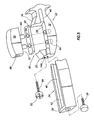
- FIG. 6 is an exploded, perspective view of a sixth embodiment of a vertebral disk stabilizer constructed in accordance with the teachings of the present invention.
- FIG. 7 is a perspective view of the stabilizer of FIG. 6 showing a band for minimizing the height to facilitate insertion into the intervertebral disk space.
- FIG. 8 is an exploded, perspective view of seventh embodiment of a vertebral disk stabilizer constructed in accordance with the teachings of the present invention.
- Stabilizer 20 is intended to be implanted between the bodies of two adjacent vertebrae in the disk space from which a portion of the intervertebral disk has been removed, i.e. by simple diskectomy and small laminotomy.
- the vertebral disk stabilizer 20 is comprised of an elongate implant 22 , lock 24 , and means for detachably mounting the lock 24 to one end 25 of the implant 22 .
- the mounting means takes the form of a bolt 26 passing through a bore 28 in lock 24 , the threads of bolt 26 engaging complementary threads in the walls of the bore 30 in the end 25 of implant 22 .
- a lock nut (not shown) may optionally be provided for resisting the loosening of the bolt 26 once lock 24 is mounted to implant 22 in the manner described below.
- implant 22 is comprised of first and second sides 32 and third and fourth sides 34 providing a substantially rectangularly shaped cross-section.
- the height of the rectangularly shaped cross-section is defined by first and second sides 32 and the width is defined by the third and fourth sides 34 and, as is apparent by comparison of the height and width, the width of implant 22 is less than the height.
- height is minimized to facilitate insertion of the second end 36 into, and positioning of implant 22 in, the disk space from which a portion of the intervertebral disk has been removed and width is maximized so that, when implant 22 is rotated by approximately 90°, implant 22 provides the desired distraction of the adjacent vertebrae.
- Third and fourth sides 34 are arched from one end of implant 22 to the other to provide the portion of implant 22 intermediate the ends 25 and 36 with a height that is larger than the height at the ends 25 and 36 . Because the sides 32 of implant 22 are substantially flat and the sides 34 are arched from one end 25 to the other end 36 , implant 22 is described as being a bi-planar, bi-convex implant.
- the bi-convex sides 34 of implant 22 are optionally provided with a plurality of teeth (not shown) for biting into the adjacent vertebrae to help resist anterior-posterior movement of implant 22 in the disk space as explained in more detail below.
- the end 36 of implant 22 is provided with a flare, or “whale tail,” 38 for this same reason, it being critical to resist such anterior-posterior movement so as to reduce the likelihood of injury to the nerves of the spinal cord both during insertion of implant 22 into the disk space and after implantation.
- lock 24 is substantially square when viewed from the end 40 along the axis of the bore 28 therethrough and “U”-shaped when viewed from the side.
- the inside surfaces 42 of the arms 44 of the “U”-shaped lock 24 are flat for contacting the first and second sides 32 of implant 22 to prevent rotation of lock 24 relative to implant 22 when lock 24 is mounted to implant 22 and secured thereto by bolt 26 .
- the sides 32 of implant 22 are provided with a key 46 that is received in a complementary-shaped keyway 48 formed in the surface 42 of the arms 44 of lock 24 to facilitate assembly of lock 24 to implant 22 ; those skilled in the art who have the benefit of this disclosure will recognize that (as shown in FIGS.
- the key 46 may be located on the lock 24 and keyway 48 may be located on implant 22 without any difference in the manner in which those component parts function.
- the mouth of the keyway 48 at the ends of the arms 44 of lock 24 may be wider than the width of the key 46 to facilatate insertion of keys 46 into keyways 48 .
- the sides of the square end 40 of lock 24 provide surfaces 50 for bearing against the bodies of the adjacent vertebrae as also explained in more detail below. It will be recognized by those skilled in the art who have the benefit of this disclosure that the bearing surfaces 50 need not be flat and that the end 40 of lock 24 need not be square. Other shapes and configurations may be utilized as needed to insure that movement of lock 24 , and the implant 22 once lock 24 is mounted to implant 22 , is limited by engagement of the bodies of the adjacent vertebrae by the vertebral bearing surfaces 50 .
- the purpose of the bi-planar, middle expanded, bi-convex implant 22 is to enable insertion of the implant 22 into the disk space and turning by approximately 90° to increase the disk height and stabilize the disk space.
- lock 24 is to lock implant 22 against instability when in the vertical position so as to maintain the disk height thereafter.
- An applicator (not shown) of the type described in U.S. Pat. No. 5,658,336, which patent is hereby incorporated into this specification in its entirety by this specific reference thereto, is mounted to the end 25 of implant 22 by screwing the threaded end of the applicator into the threaded bore 30 in implant 22 .
- implant 22 is inserted into the disk space with the wide sides 32 (so that the height of implant 22 is of minimal dimension) proximate the bodies of the adjacent vertebrae and rotated in the disk space by approximately 90° using the applicator so that the minimally-dimensioned sides 34 are proximate the bodies of the adjacent vertebrae so as to maximize the height of implant 22 in the disk space.
- the procedure for placement of the implant 22 is set out in more detail below.
- the applicator is then detached from implant 22 by rotating in the opposite direction while rotation of implant 22 is restrained.
- bolt 52 which extends into the portion of the threaded bore 54 A in implant 22 in the end 25 of implant 22 and the portion 54 B in the insert portion 56 of implant 22 , is backed out of implant 22 .
- Backing bolt 52 out of threaded bore 54 B releases insert 56 , which is biased away from the landing 58 in the implant 22 by springs 60 , from a first, compressed position to a second position in which the insert 56 floats on springs 60 so that the portion 34 A of the side 34 of implant 22 comprising insert 56 contacts the body of a vertebrae adjacent the disk space.
- biasing insert 56 toward the adjacent vertebrae in this fashion provides the cushioning function that is lacking from prior known intervertebral implants.
- the pistons 62 on the underside 57 (the side adjacent landing 58 ) of insert 56 are received in complimentary-shaped and sized recesses, or blind bores, 64 to maintain alignment of the insert 56 with implant 22 as insert 56 moves relative to implant 22 , and a stop 66 formed on one end of insert 56 is engaged by the lip 68 formed by the cap 70 that is secured to implant 22 by cap screw 71 to limit movement of insert 56 away from landing 58 .
- the springs 60 bear against the landing 58 of implant 22 and the underside 57 of insert 56 to bias insert 56 away from landing 58 .
- the adjacent surfaces 72 A, 72 B and 74 A, 74 B of insert 56 and implant 22 are shaped in complementary curves so as to assist in maintaining alignment between insert 56 and implant 22 as insert 56 moves relative to implant 22 .
- the adjacent surfaces 72 A, 72 B and 74 A, 74 B may be provided with a key and keyway or other structure that functions to maintain alignment between insert 54 and implant 22 as insert 54 moves relative to implant 22 in the disk space and that the present invention contemplates any and all such structure that functions in this manner to accomplish the result of maintaining alignment.
- Stabilizer 76 includes most of the same component parts as shown in the stabilizer 20 shown in FIG. 1 and the reference numerals utilized in FIG. 2 are therefore the same as are utilized in describing the component parts of stabilizer 20 shown in FIG. 1 (and for the same reason, the same numbering scheme is also utilized in describing the embodiments shown in FIGS. 3-7 ).
- the stabilizer 76 shown in FIG. 2 is provided with leaf spring 78 that is received within the cavity 80 formed on the underside 57 of insert 56 .
- stabilizer 76 functions in the same manner as stablilizer 20 .
- a third embodiment of a stabilizer constructed in accordance with the teachings of the present invention is indicated generally at reference numeral 82 in FIG. 3 .
- Stabilizer 82 differs from stabilizer 20 ( FIG. 1 ) in that the threaded portion of bolt 52 is provided with a weak point, indicated at reference numeral 84 , and that either a portion of bore 54 A extending through implant 22 or a portion of the bolt 52 proximate the head thereof is unthreaded.
- Bolt 52 initially resides in the bore 54 extending through the end 25 of implant 22 and into insert 56 to hold insert 56 in the first position in which the coil springs 60 are compressed and the underside 57 of insert 56 is proximate the landing 58 of implant 22 while implant 22 is inserted into the disk space and then rotated approximately 90° as described briefly above and in more detail below.
- Bolt 52 is then backed out of bore 54 until it extends only part way into the bore 54 B in insert 56 , freeing insert 56 from the first, compressed position in which the underside 57 of insert 56 is proximate the landing 58 of implant 22 so that it is biased away from landing 58 by springs 60 .
- the bolt 52 is then broken at the point 84 and the head and broken portion of bolt 52 are removed from the bore 54 A and from implant 22 .
- removing the bolt 52 from the end 25 of implant 22 allows a close fit between lock 24 and the end 25 of implant 22 when lock 24 is mounted thereto.
- the portion of bolt 52 that remains in the threaded portion of bore 54 A, after bolt 52 was backed part way out of bore 54 extends only part way into the bore 54 B in insert 56 so that insert 56 is retained in alignment with implant 22 by movement of the remaining threaded portion of bolt 52 in the channel 86 formed in the surface 72 A of insert 56 , the bottoming out of bolt 52 in channel 86 also acting as a stop to limit the movement of insert 56 away from landing 58 . Referring to FIG.
- a fourth embodiment of a stabilizer constructed in accordance with the teachings of the present invention shown at reference numeral 88 , is likewise provided with a bolt 52 having the same break point 84 as shown in the stabilizer 82 ( FIG. 3 ), unthreaded proximal portion of bore 54 A, and channel 86 , all of which function in the same manner as described in connection with the embodiment shown in FIG. 3
- a fifth embodiment of a stabilizer constructed in accordance with the teachings of the present invention is designated generally by reference numeral 90 in FIG. 5 .
- Stabilizer 90 is likewise provided with the break point 84 in bolt 52 and channel 86 in the same manner as stabilizer 82 in FIG. 3 , but instead of coil springs around the pistons 62 of insert 56 , stabilizer 90 is provided with a pad 92 comprised of a highly compressible, springy material that is preferably biologically inert that functions in the manner of the springs 60 shown in FIGS. 1 and 3 .
- Such materials are known to those skilled in the art but, by way of example, certain polyurethanes and other medical grade polymers will function for the intended purpose.
- the pistons 62 of insert 56 pass through holes 94 cut through pad 92 .
- Stabilizer 96 is provided with two inserts 56 A and 56 B on opposite sides of implant 22 , each insert 56 A, 56 B being comprised of a compressible, springy material that is preferably biologically inert such that the entire insert 56 A, 56 B is biased into engagement with the adjacent vertebrae in the same manner of the springs 60 ( FIGS. 1 and 3 ), leaf springs 78 ( FIGS. 2 and 4 ), and pad ( FIG. 5 ) when the band 98 that initially encircles the implant 22 ( FIG. 7 ) is cut and then removed from the intervertebral space.
- the inserts 56 A, 56 B are shaped with flanges 100 that are received within the complementary-shaped undercuts 102 formed on both sides of implant 22 adjacent the landings 58 A, 58 B, and the inserts 56 A, 56 B are retained to and in alignment with implant 22 by the interaction between the flanges 100 , undercuts 102 and the curves surfaces 72 A, 72 B and 74 A, 74 B.
- the three-piece implant 22 of stabilizer 96 is assembled by snapping the inserts 56 A, 56 B into place on either side of landings 58 A, 58 B, the compressible nature of the material comprising the inserts 56 A, 56 B providing enough resilience that the inserts 56 A, 56 B must be forced into place and then, once snapped into that place, retained therein.
- the key 46 and keyway 48 on implant 22 and lock 24 may be reversed from the arrangement shown in FIGS. 1-5 such that key 46 is located on lock 24 and keyway 48 is located on implant 22 , and the stabilizer 96 shown in FIGS. 6 and 7 illustrates such an arrangement.
- the funnel-shaped portion 47 of the keyway 48 behind the mouth 45 at the end 25 of implant 22 which gradually decreases in width, acts to increase the ease with which lock 24 is mounted to implant 22 by insertion of the keys 46 on lock 24 into the respective keyways 48 on implant 22 and helps to seat lock 24 thereon and align the bore 28 in lock 24 with the bore 30 in implant 22 .
- Implant 104 differs from the implants 22 of stabilizer 20 ( FIG. 1 ), stabilizer 76 ( FIG. 2 ), stablizer 82 ( FIG. 3 ), stabilizer 88 ( FIG. 4 ), stabilizer 90 ( FIG. 5 ), or stabilizer 96 ( FIGS. 6-7 ) in that the inserts 106 comprising a portion of implant 104 are sized so that the surface 34 A of insert 106 extends out of, or are not flush with, the surface 34 of implant 104 . As with the inserts 56 of stabilizer 96 ( FIGS.
- the inserts 106 of implant 104 are comprised of a material that is highly compressible and springy, or spongy, and that is preferably biologically inert, and is initially compressed by a band in the same manner as shown in FIG. 7 .
- the entire insert 106 functions as a cushion between vertebrae in the same manner as described in connection with the embodiments shown in FIGS. 1-7 .
- the stabilizer of the present invention in, for instance, a method of lumbar intervertebral disk stabilization will now be described.
- Surgery is performed as in a simple diskectomy and the intervertebral disk 20 is exposed through a small laminotomy.
- the herniated portion of the disk is removed and any nerve root compression is corrected.
- the posterior longitudinal ligament (not shown) and disk cartilage are removed until the surfaces of the bodies of the adjacent vertebrae are exposed above and below the disk space, but the portions of the disk on either side of the defect are retained.
- the positioning of the lock 24 at the opening to the disk space as described below virtually seals off the opening to the disk space, making the likelihood of recurring herniation of the disk negligible. Further, the posterior longitudinal ligament is left intact to the opposite side and to the center of the disk space.
- the present invention also contemplates the use of a medical grade adhesive in sealing the opening to the disk space.
- a medical grade adhesive in sealing the opening to the disk space.
- Another modification of the method described herein is the use of various hydrogels, either with or without an adhesive, in the intervertebral space.
- One type of hydrogel that is suitable for the intended purpose is a group of polymers referred to as protein polymers. These polymers are described, for instance, in U.S. Pat. Nos. 5,514,581 and 6,184,348 and in D. C. Martin, et al., “Processing and characterization of protein polymers,” in Protein-Based Materials, K. McGrath and D. Kaplan, Eds. (1996).
- PVP polyvinylpyrolidine
- hydrogels are injected or otherwise introduced into the intervertebral disk space before or after the implant 22 is inserted to fill the space around the implant and the highly viscous “glob” fills the voids in the disk space and functions to help retain the remaining portion of the intervertebral disk intact and further reduce the likelihood of any recurrent herniation of the disk from the opening into the disk space.
- the disk space may also be injected or otherwise provided with the above-described medical grade adhesive for the purpose of helping bind the hydrogel to the disk material and/or helping to maintain the integrity of the remaining disk material.
- the implant 22 is positioned in the disk space at a position in which the expanded, middle portion and the smaller width ends 25 and 36 of the third and fourth sides 34 of implant 22 contact the respective lower and upper surfaces of the bodies of the adjacent vertebrae when rotated by approximately 90°.
- the respective lower and upper surfaces of the vertebral bodies are slightly concave such that the larger width middle portion of implant 22 allows the implant 22 to engage substantially more of the surfaces of the vertebral bodies of the adjacent verterbrae than conventional prosthetic devices, thereby providing increased stability to the implant once further rotation of implant 22 in the disk space is prevented as described below.
- the applicator is detached from implant 22 by backing the applicator out of the incision in the patient.
- Lock 24 is then inserted through that same incision and, using the key 46 and keyway 48 , the bore 28 in lock 24 and bore 30 in implant 22 are aligned and the bolt 26 is inserted and tightened to secure lock 24 to the implant 22 .
- Securing the lock 24 to implant 22 in this manner resists relative rotation between lock 24 and implant 22 and the bearing surfaces 50 of lock 24 bear against the bodies of the adjacent vertebrae to resist rotation of the lock 24 relative to the adjacent vertebrae against which the bearing surfaces 50 bear.
- the bearing surfaces 50 bear against the cortical end plate of the respective vertebral bodies, which is comprised of non-cancellous bone, and provides a hard, relatively smooth surface against which the bearing surfaces 50 bear.
- the bearing surfaces 50 of lock 24 are oriented at an angle of approximately 90° to the height of implant 22 .
- the end 40 of lock 24 is preferably supplied in a plurality of different sizes and shapes other than the square shaped end 40 shown in the figures so as to allow the surgeon to select an appropriately-sized and shaped lock that provides a close fit with the space between vertebral bodies.
- the first and second sides of the implant are substantially flat but not parallel along their longitudinal axes so that the implant is wedge-shaped.
- the wedge shape of the implant facilitates insertion of the implant into the disk space, the rounded end of the implant reducing the likelihood of injury to the nerves of the spinal cord during insertion into the disk space.
- the width at one end of the implant can be less than the width at the end, both widths, however, being less than the width in the middle, expanded portion of the implant.
- the connection by which lock 24 is mounted to implant 22 is capable of being constructed in a manner different than that shown in the figures herein.
- Another such modification relates to manner in which the insert 56 is retained in the first and/or compressed position proximate landing 58 , it being recognized by those skilled in the art that instead of using the bolt 52 for that purpose, the key 46 and keyway 48 may be used to restrain movement of insert 56 away from landing 58 .
- Another modification relates to the above-described medical grade adhesive and protein polymers.
- an adhesive may be utilized to seal the opening to the disk space and/or to facilitate bonding of the protein polymer or other type of hydrogel to the remaining disk material.
- the bore 28 in lock 24 is provided with a reservoir of adhesive that, when punctured by insertion of the bolt 26 therein, causes the adhesive to exude out of bore 28 and into the opening to the disk space as the bolt 26 squeezes the contents from the reservoir as it is tightened against the lock 24 .
- implant 22 is provided with a reservoir of protein polymers, for instance, at the end 36 that is punctured by the point of the key 46 as the key slides into a keyway such as the keyway 48 on both sides of the implant 22 of stabilizer 96 shown in FIGS. 6 and 7 . All such modifications, and other modifications that do not depart from the spirit of the present invention, are intended to fall within the scope of the following claims.
Abstract
Description
Claims (18)
Priority Applications (10)
| Application Number | Priority Date | Filing Date | Title |
|---|---|---|---|
| US10/804,895 US7879095B2 (en) | 1994-03-18 | 2004-03-19 | Method of inserting, rotating and releasing a spring-loaded artificial disk |
| MXPA06010740A MXPA06010740A (en) | 2004-03-19 | 2005-03-19 | Rotating, locking, spring-loaded artificial disk. |
| JP2007504179A JP2007529286A (en) | 2004-03-19 | 2005-03-19 | Rotating, fixed, spring-biased artificial disc |
| EP05725974A EP1737395B1 (en) | 2004-03-19 | 2005-03-19 | Rotating, locking, spring-loaded artificial disk |
| DE602005016909T DE602005016909D1 (en) | 2004-03-19 | 2005-03-19 | ROTATABLE, LOCKING, SPRING LOADED BRAKE PEDESTAL |
| CA002560237A CA2560237A1 (en) | 2004-03-19 | 2005-03-19 | Rotating, locking, spring-loaded artificial disk |
| PCT/US2005/009323 WO2005092250A1 (en) | 2004-03-19 | 2005-03-19 | Rotating, locking, spring-loaded artificial disk |
| AT05725974T ATE444040T1 (en) | 2004-03-19 | 2005-03-19 | ROTATABLE, LOCKING, SPRING-LOADED DISC PROSTHESIS |
| US11/440,552 US20060282165A1 (en) | 2004-03-19 | 2006-05-25 | Intervertebral disc implant |
| US12/930,484 US8480740B2 (en) | 2004-03-19 | 2011-01-07 | Rotating, locking, spring-loaded artificial disk |
Applications Claiming Priority (7)
| Application Number | Priority Date | Filing Date | Title |
|---|---|---|---|
| US08/210,229 US6093207A (en) | 1994-03-18 | 1994-03-18 | Middle expanded, removable intervertebral disk stabilizer disk |
| PCT/US1995/003374 WO1995025487A1 (en) | 1994-03-18 | 1995-03-17 | Middle expanded, removable intervertebral disk stabilizer and method of lumbar intervertebral disk stabilization |
| US08/475,211 US5658336A (en) | 1994-03-18 | 1995-06-07 | Rotating, locking, middle-expanded intervertebral disk stabilizer |
| US08/900,174 US5893890A (en) | 1994-03-18 | 1997-07-25 | Rotating, locking intervertebral disk stabilizer and applicator |
| US09/290,831 US6309421B1 (en) | 1994-03-18 | 1999-04-13 | Rotating, locking intervertebral disk stabilizer and applicator |
| US56148300A | 2000-04-28 | 2000-04-28 | |
| US10/804,895 US7879095B2 (en) | 1994-03-18 | 2004-03-19 | Method of inserting, rotating and releasing a spring-loaded artificial disk |
Related Parent Applications (1)
| Application Number | Title | Priority Date | Filing Date |
|---|---|---|---|
| US56148300A Continuation-In-Part | 1994-03-18 | 2000-04-28 |
Related Child Applications (2)
| Application Number | Title | Priority Date | Filing Date |
|---|---|---|---|
| US11/440,552 Continuation-In-Part US20060282165A1 (en) | 2004-03-19 | 2006-05-25 | Intervertebral disc implant |
| US12/930,484 Division US8480740B2 (en) | 2004-03-19 | 2011-01-07 | Rotating, locking, spring-loaded artificial disk |
Publications (2)
| Publication Number | Publication Date |
|---|---|
| US20050065610A1 US20050065610A1 (en) | 2005-03-24 |
| US7879095B2 true US7879095B2 (en) | 2011-02-01 |
Family
ID=34963305
Family Applications (2)
| Application Number | Title | Priority Date | Filing Date |
|---|---|---|---|
| US10/804,895 Expired - Fee Related US7879095B2 (en) | 1994-03-18 | 2004-03-19 | Method of inserting, rotating and releasing a spring-loaded artificial disk |
| US12/930,484 Active 2024-10-05 US8480740B2 (en) | 2004-03-19 | 2011-01-07 | Rotating, locking, spring-loaded artificial disk |
Family Applications After (1)
| Application Number | Title | Priority Date | Filing Date |
|---|---|---|---|
| US12/930,484 Active 2024-10-05 US8480740B2 (en) | 2004-03-19 | 2011-01-07 | Rotating, locking, spring-loaded artificial disk |
Country Status (8)
| Country | Link |
|---|---|
| US (2) | US7879095B2 (en) |
| EP (1) | EP1737395B1 (en) |
| JP (1) | JP2007529286A (en) |
| AT (1) | ATE444040T1 (en) |
| CA (1) | CA2560237A1 (en) |
| DE (1) | DE602005016909D1 (en) |
| MX (1) | MXPA06010740A (en) |
| WO (1) | WO2005092250A1 (en) |
Cited By (10)
| Publication number | Priority date | Publication date | Assignee | Title |
|---|---|---|---|---|
| US8029574B2 (en) | 2006-11-07 | 2011-10-04 | Biomedflex Llc | Prosthetic knee joint |
| US8070823B2 (en) | 2006-11-07 | 2011-12-06 | Biomedflex Llc | Prosthetic ball-and-socket joint |
| US8308812B2 (en) | 2006-11-07 | 2012-11-13 | Biomedflex, Llc | Prosthetic joint assembly and joint member therefor |
| US8512413B2 (en) | 2006-11-07 | 2013-08-20 | Biomedflex, Llc | Prosthetic knee joint |
| US9005307B2 (en) | 2006-11-07 | 2015-04-14 | Biomedflex, Llc | Prosthetic ball-and-socket joint |
| US9005306B2 (en) | 2006-11-07 | 2015-04-14 | Biomedflex, Llc | Medical Implants With Compliant Wear-Resistant Surfaces |
| US9445918B1 (en) | 2012-10-22 | 2016-09-20 | Nuvasive, Inc. | Expandable spinal fusion implants and related instruments and methods |
| US9566157B2 (en) | 2006-11-07 | 2017-02-14 | Biomedflex, Llc | Three-member prosthetic joint |
| US20180000610A1 (en) * | 2012-10-01 | 2018-01-04 | DePuy Synthes Products, Inc. | Interbody fusion implant |
| US10123829B1 (en) | 2015-06-15 | 2018-11-13 | Nuvasive, Inc. | Reduction instruments and methods |
Families Citing this family (79)
| Publication number | Priority date | Publication date | Assignee | Title |
|---|---|---|---|---|
| US7041309B2 (en) | 2002-06-13 | 2006-05-09 | Neuropro Technologies, Inc. | Spinal fusion using an HMG-CoA reductase inhibitor |
| US6793678B2 (en) | 2002-06-27 | 2004-09-21 | Depuy Acromed, Inc. | Prosthetic intervertebral motion disc having dampening |
| US20040098129A1 (en) * | 2002-11-13 | 2004-05-20 | Jo-Wen Lin | Spinal implant insertion adjustment instrument and implants for use therewith |
| US8597360B2 (en) | 2004-11-03 | 2013-12-03 | Neuropro Technologies, Inc. | Bone fusion device |
| JP4601051B2 (en) * | 2004-12-20 | 2010-12-22 | 株式会社ユニバーサルエンターテインメント | Gaming chips |
| US20060276899A1 (en) * | 2005-06-03 | 2006-12-07 | Zipnick Richard I | Minimally invasive apparatus to manipulate and revitalize spinal column disc |
| US20060276901A1 (en) * | 2005-06-03 | 2006-12-07 | Zipnick Richard I | Minimally invasive apparatus to manipulate and revitalize spinal column disc |
| US7727279B2 (en) * | 2005-06-03 | 2010-06-01 | Zipnick Richard I | Minimally invasive apparatus to manipulate and revitalize spinal column disc |
| US20060276902A1 (en) * | 2005-06-03 | 2006-12-07 | Zipnick Richard I | Minimally invasive apparatus to manipulate and revitalize spinal column disc |
| US7883542B2 (en) * | 2005-06-03 | 2011-02-08 | Zipnick Richard I | Minimally invasive apparatus to manipulate and revitalize spinal column disc |
| US7909872B2 (en) * | 2005-06-03 | 2011-03-22 | Zipnick Richard I | Minimally invasive apparatus to manipulate and revitalize spinal column disc |
| US7879099B2 (en) * | 2005-06-03 | 2011-02-01 | Zipnick Richard I | Minimally invasive apparatus to manipulate and revitalize spinal column disc |
| US20070135827A1 (en) * | 2005-12-12 | 2007-06-14 | Zipnick Richard I | Method and apparatus to penetrate soft tissue and produce passageway in hard tissue while protecting principal vasculature and nerves |
| US8137404B2 (en) * | 2006-03-28 | 2012-03-20 | Depuy Spine, Inc. | Artificial disc replacement using posterior approach |
| US20070233244A1 (en) * | 2006-03-28 | 2007-10-04 | Depuy Spine, Inc. | Artificial Disc Replacement Using Posterior Approach |
| US8282641B2 (en) | 2006-03-28 | 2012-10-09 | Depuy Spine, Inc. | Methods and instrumentation for disc replacement |
| US9526525B2 (en) | 2006-08-22 | 2016-12-27 | Neuropro Technologies, Inc. | Percutaneous system for dynamic spinal stabilization |
| US20080108990A1 (en) * | 2006-11-02 | 2008-05-08 | St. Francis Medical Technologies, Inc. | Interspinous process implant having a fixed wing and a deployable wing and method of implantation |
| US8105382B2 (en) | 2006-12-07 | 2012-01-31 | Interventional Spine, Inc. | Intervertebral implant |
| US11395626B2 (en) | 2006-12-07 | 2022-07-26 | DePuy Synthes Products, Inc. | Sensor for intervertebral fusion indicia |
| US8715352B2 (en) * | 2006-12-14 | 2014-05-06 | Depuy Spine, Inc. | Buckling disc replacement |
| US8034081B2 (en) | 2007-02-06 | 2011-10-11 | CollabComl, LLC | Interspinous dynamic stabilization implant and method of implanting |
| US8298287B2 (en) * | 2007-06-26 | 2012-10-30 | Depuy Spine, Inc. | Intervertebral motion disc with helical shock absorber |
| US8900307B2 (en) | 2007-06-26 | 2014-12-02 | DePuy Synthes Products, LLC | Highly lordosed fusion cage |
| EP2237748B1 (en) | 2008-01-17 | 2012-09-05 | Synthes GmbH | An expandable intervertebral implant |
| CA2720580A1 (en) | 2008-04-05 | 2009-10-08 | Synthes Usa, Llc | Expandable intervertebral implant |
| ES2401235T3 (en) * | 2008-05-07 | 2013-04-18 | University Of Strathclyde | System and method for cell characterization |
| ES2361099B1 (en) * | 2008-05-26 | 2012-05-08 | Rudolf Morgenstern Lopez | "INTERVERTEBRAL PROSTHESIS" |
| US9526620B2 (en) | 2009-03-30 | 2016-12-27 | DePuy Synthes Products, Inc. | Zero profile spinal fusion cage |
| US9642722B2 (en) | 2009-07-02 | 2017-05-09 | Atlas Spine, Inc. | Intervertebral expandable spacer |
| US8529627B2 (en) * | 2009-07-02 | 2013-09-10 | Atlas Spine, Inc. | Intervertebral spacer |
| US9393129B2 (en) | 2009-12-10 | 2016-07-19 | DePuy Synthes Products, Inc. | Bellows-like expandable interbody fusion cage |
| US9827031B2 (en) * | 2010-05-28 | 2017-11-28 | Benvenue Medical, Inc. | Disc space sizing devices |
| US9907560B2 (en) | 2010-06-24 | 2018-03-06 | DePuy Synthes Products, Inc. | Flexible vertebral body shavers |
| US8979860B2 (en) | 2010-06-24 | 2015-03-17 | DePuy Synthes Products. LLC | Enhanced cage insertion device |
| AU2011271465B2 (en) | 2010-06-29 | 2015-03-19 | Synthes Gmbh | Distractible intervertebral implant |
| US20120029639A1 (en) * | 2010-07-29 | 2012-02-02 | Warsaw Orthopedic, Inc. | Interbody spinal implants and insertion techniques |
| US9402732B2 (en) | 2010-10-11 | 2016-08-02 | DePuy Synthes Products, Inc. | Expandable interspinous process spacer implant |
| US10420654B2 (en) | 2011-08-09 | 2019-09-24 | Neuropro Technologies, Inc. | Bone fusion device, system and method |
| US9358123B2 (en) | 2011-08-09 | 2016-06-07 | Neuropro Spinal Jaxx, Inc. | Bone fusion device, apparatus and method |
| WO2013023096A1 (en) | 2011-08-09 | 2013-02-14 | Neuropro Technologies, Inc. | Bone fusion device, system and method |
| US9668783B2 (en) | 2011-09-06 | 2017-06-06 | Atul Goel | Devices and method for treatment of spondylotic disease |
| US10159583B2 (en) | 2012-04-13 | 2018-12-25 | Neuropro Technologies, Inc. | Bone fusion device |
| US9532883B2 (en) | 2012-04-13 | 2017-01-03 | Neuropro Technologies, Inc. | Bone fusion device |
| US8940052B2 (en) | 2012-07-26 | 2015-01-27 | DePuy Synthes Products, LLC | Expandable implant |
| US20140067069A1 (en) | 2012-08-30 | 2014-03-06 | Interventional Spine, Inc. | Artificial disc |
| US9522070B2 (en) | 2013-03-07 | 2016-12-20 | Interventional Spine, Inc. | Intervertebral implant |
| AU2014236698B2 (en) | 2013-03-15 | 2018-09-13 | Neuropro Technologies, Inc. | Bodiless bone fusion device, apparatus and method |
| US9198774B2 (en) * | 2013-11-21 | 2015-12-01 | Perumala Corporation | Intervertebral disk cage and stabilizer |
| US10314605B2 (en) | 2014-07-08 | 2019-06-11 | Benvenue Medical, Inc. | Apparatus and methods for disrupting intervertebral disc tissue |
| US10022243B2 (en) | 2015-02-06 | 2018-07-17 | Benvenue Medical, Inc. | Graft material injector system and method |
| US11426290B2 (en) | 2015-03-06 | 2022-08-30 | DePuy Synthes Products, Inc. | Expandable intervertebral implant, system, kit and method |
| US9913727B2 (en) | 2015-07-02 | 2018-03-13 | Medos International Sarl | Expandable implant |
| RU2641854C2 (en) * | 2015-09-10 | 2018-01-22 | ФГАОУ ВО Севастопольский государственный университет | Torsion intervertebral disk endoprosthesis |
| RU2653622C2 (en) * | 2015-12-11 | 2018-05-11 | Федеральное государственное автономное образовательное учреждение высшего образования "Севастопольский государственный университет" | Six-step intervertebral disk endoprosthesis |
| WO2017112790A1 (en) | 2015-12-21 | 2017-06-29 | Southern Spine, Llc | Expandable interbody devices and related instruments and methods for spinal fusion surgery |
| RU2642722C2 (en) * | 2016-01-12 | 2018-01-25 | Федеральное государственное автономное образовательное учреждение высшего образования "Севастопольский государственный университет" | Intervertebral disc endoprosthesis |
| RU2653621C2 (en) * | 2016-05-26 | 2018-05-11 | Федеральное государственное автономное образовательное учреждение высшего образования (ФГАОУ ВО) Севастопольский государственный университет | Interbody spinal endoprosthesis |
| RU2680917C2 (en) * | 2016-05-26 | 2019-02-28 | Федеральное государственное автономное образовательное учреждение высшего образования (ФГАОУ ВО) Севастопольский государственный университет | Membrane-torsion intervertebral disc endoprosthesis |
| US11596523B2 (en) | 2016-06-28 | 2023-03-07 | Eit Emerging Implant Technologies Gmbh | Expandable and angularly adjustable articulating intervertebral cages |
| EP3474783B1 (en) | 2016-06-28 | 2023-05-03 | Eit Emerging Implant Technologies GmbH | Expandable, angularly adjustable intervertebral cages |
| US10537436B2 (en) | 2016-11-01 | 2020-01-21 | DePuy Synthes Products, Inc. | Curved expandable cage |
| US10888433B2 (en) | 2016-12-14 | 2021-01-12 | DePuy Synthes Products, Inc. | Intervertebral implant inserter and related methods |
| US10111760B2 (en) | 2017-01-18 | 2018-10-30 | Neuropro Technologies, Inc. | Bone fusion system, device and method including a measuring mechanism |
| US10213321B2 (en) | 2017-01-18 | 2019-02-26 | Neuropro Technologies, Inc. | Bone fusion system, device and method including delivery apparatus |
| US10729560B2 (en) | 2017-01-18 | 2020-08-04 | Neuropro Technologies, Inc. | Bone fusion system, device and method including an insertion instrument |
| US10973657B2 (en) | 2017-01-18 | 2021-04-13 | Neuropro Technologies, Inc. | Bone fusion surgical system and method |
| US10758286B2 (en) | 2017-03-22 | 2020-09-01 | Benvenue Medical, Inc. | Minimal impact access system to disc space |
| US10398563B2 (en) | 2017-05-08 | 2019-09-03 | Medos International Sarl | Expandable cage |
| US11344424B2 (en) | 2017-06-14 | 2022-05-31 | Medos International Sarl | Expandable intervertebral implant and related methods |
| US10940016B2 (en) | 2017-07-05 | 2021-03-09 | Medos International Sarl | Expandable intervertebral fusion cage |
| US11583327B2 (en) | 2018-01-29 | 2023-02-21 | Spinal Elements, Inc. | Minimally invasive interbody fusion |
| WO2019178575A1 (en) | 2018-03-16 | 2019-09-19 | Benvenue Medical, Inc. | Articulated instrumentation and methods of using the same |
| US11446156B2 (en) | 2018-10-25 | 2022-09-20 | Medos International Sarl | Expandable intervertebral implant, inserter instrument, and related methods |
| AU2020353089A1 (en) * | 2019-09-24 | 2022-04-21 | Astura Medical Inc. | Standalone anterior lumber interbody spacer |
| US11426286B2 (en) | 2020-03-06 | 2022-08-30 | Eit Emerging Implant Technologies Gmbh | Expandable intervertebral implant |
| US11850160B2 (en) | 2021-03-26 | 2023-12-26 | Medos International Sarl | Expandable lordotic intervertebral fusion cage |
| US11752009B2 (en) | 2021-04-06 | 2023-09-12 | Medos International Sarl | Expandable intervertebral fusion cage |
| WO2023216003A1 (en) * | 2022-05-13 | 2023-11-16 | Caratsch Alexander | Flexible interbody cage |
Citations (48)
| Publication number | Priority date | Publication date | Assignee | Title |
|---|---|---|---|---|
| US4309777A (en) | 1980-11-13 | 1982-01-12 | Patil Arun A | Artificial intervertebral disc |
| US4401112A (en) | 1980-09-15 | 1983-08-30 | Rezaian Seyed M | Spinal fixator |
| US4553273A (en) | 1983-11-23 | 1985-11-19 | Henry Ford Hospital | Vertebral body prosthesis and spine stabilizing method |
| US4657550A (en) * | 1984-12-21 | 1987-04-14 | Daher Youssef H | Buttressing device usable in a vertebral prosthesis |
| EP0260044A1 (en) | 1986-08-29 | 1988-03-16 | John Anthony Norman Shepperd | Spinal implant |
| US4759769A (en) * | 1987-02-12 | 1988-07-26 | Health & Research Services Inc. | Artificial spinal disc |
| DE3729600A1 (en) | 1987-09-04 | 1989-03-16 | Aesculap Werke Ag | Implant for insertion between the vertebral bodies of the spine |
| US4932975A (en) | 1989-10-16 | 1990-06-12 | Vanderbilt University | Vertebral prosthesis |
| US5059193A (en) | 1989-11-20 | 1991-10-22 | Spine-Tech, Inc. | Expandable spinal implant and surgical method |
| US5123926A (en) | 1991-02-22 | 1992-06-23 | Madhavan Pisharodi | Artificial spinal prosthesis |
| US5171278A (en) * | 1991-02-22 | 1992-12-15 | Madhavan Pisharodi | Middle expandable intervertebral disk implants |
| US5197978A (en) * | 1991-04-26 | 1993-03-30 | Advanced Coronary Technology, Inc. | Removable heat-recoverable tissue supporting device |
| US5236460A (en) | 1990-02-12 | 1993-08-17 | Midas Rex Pneumatic Tools, Inc. | Vertebral body prosthesis |
| US5290312A (en) * | 1991-09-03 | 1994-03-01 | Alphatec | Artificial vertebral body |
| US5390683A (en) * | 1991-02-22 | 1995-02-21 | Pisharodi; Madhavan | Spinal implantation methods utilizing a middle expandable implant |
| US5443514A (en) * | 1993-10-01 | 1995-08-22 | Acromed Corporation | Method for using spinal implants |
| US5458641A (en) | 1993-09-08 | 1995-10-17 | Ramirez Jimenez; Juan J. | Vertebral body prosthesis |
| US5522899A (en) | 1988-06-28 | 1996-06-04 | Sofamor Danek Properties, Inc. | Artificial spinal fusion implants |
| WO1996040016A2 (en) | 1994-03-18 | 1996-12-19 | Madhavan Pisharodi | Intervertebral disk stabilizer and instrument for reduction of spondylolisthesis |
| US5658336A (en) * | 1994-03-18 | 1997-08-19 | Pisharodi; Madhavan | Rotating, locking, middle-expanded intervertebral disk stabilizer |
| US5658335A (en) * | 1995-03-09 | 1997-08-19 | Cohort Medical Products Group, Inc. | Spinal fixator |
| US5667522A (en) * | 1994-03-03 | 1997-09-16 | Medinol Ltd. | Urological stent and deployment device therefor |
| US5669909A (en) * | 1995-03-27 | 1997-09-23 | Danek Medical, Inc. | Interbody fusion device and method for restoration of normal spinal anatomy |
| US5800550A (en) * | 1996-03-13 | 1998-09-01 | Sertich; Mario M. | Interbody fusion cage |
| US5827328A (en) * | 1996-11-22 | 1998-10-27 | Buttermann; Glenn R. | Intervertebral prosthetic device |
| US5893890A (en) * | 1994-03-18 | 1999-04-13 | Perumala Corporation | Rotating, locking intervertebral disk stabilizer and applicator |
| US5989291A (en) * | 1998-02-26 | 1999-11-23 | Third Millennium Engineering, Llc | Intervertebral spacer device |
| US6019793A (en) * | 1996-10-21 | 2000-02-01 | Synthes | Surgical prosthetic device |
| US6080158A (en) * | 1999-08-23 | 2000-06-27 | Lin; Chih-I | Intervertebral fusion device |
| US6176882B1 (en) * | 1998-02-20 | 2001-01-23 | Biedermann Motech Gmbh | Intervertebral implant |
| US6206922B1 (en) * | 1995-03-27 | 2001-03-27 | Sdgi Holdings, Inc. | Methods and instruments for interbody fusion |
| US6264695B1 (en) * | 1999-09-30 | 2001-07-24 | Replication Medical, Inc. | Spinal nucleus implant |
| US6264655B1 (en) | 1995-06-07 | 2001-07-24 | Madhavan Pisharodi | Cervical disk and spinal stabilizer |
| US6309421B1 (en) | 1994-03-18 | 2001-10-30 | Madhavan Pisharodi | Rotating, locking intervertebral disk stabilizer and applicator |
| WO2001082844A2 (en) | 2000-04-28 | 2001-11-08 | Perumala Corporation | Rotating, locking intervertebral disk stabilizer |
| US6419724B1 (en) * | 1997-12-03 | 2002-07-16 | Sidmar N.V. | Method for reducing iron oxides and for melting iron and installations therefor |
| US6419705B1 (en) * | 1999-06-23 | 2002-07-16 | Sulzer Spine-Tech Inc. | Expandable fusion device and method |
| US6428576B1 (en) * | 1999-04-16 | 2002-08-06 | Endospine, Ltd. | System for repairing inter-vertebral discs |
| US6454806B1 (en) * | 1999-07-26 | 2002-09-24 | Advanced Prosthetic Technologies, Inc. | Spinal surgical prosthesis |
| US6478822B1 (en) * | 2001-03-20 | 2002-11-12 | Spineco, Inc. | Spherical spinal implant |
| US20030069639A1 (en) * | 2001-04-14 | 2003-04-10 | Tom Sander | Methods and compositions for repair or replacement of joints and soft tissues |
| US6669731B2 (en) * | 2001-10-18 | 2003-12-30 | Spinecore, Inc. | Intervertebral spacer device having a slotted domed arch strip spring |
| US6746484B1 (en) * | 1997-08-26 | 2004-06-08 | Society De Fabrication De Materiel De Orthopedique, S.A. | Spinal implant |
| US20040111161A1 (en) * | 2002-12-10 | 2004-06-10 | Trieu Hai H. | System and method for blocking and/or retaining a prosthetic spinal implant |
| US6863689B2 (en) * | 2001-07-16 | 2005-03-08 | Spinecore, Inc. | Intervertebral spacer having a flexible wire mesh vertebral body contact element |
| US6936070B1 (en) * | 2001-01-17 | 2005-08-30 | Nabil L. Muhanna | Intervertebral disc prosthesis and methods of implantation |
| US20080215153A1 (en) * | 2003-08-07 | 2008-09-04 | Buttermann Glenn Robin | Apparatus and method for performing spinal surgery |
| US7776094B2 (en) * | 1998-05-27 | 2010-08-17 | Nuvasive, Inc. | Spinal implants and methods for inserting spinal implants into intervertebral spaces |
Family Cites Families (6)
| Publication number | Priority date | Publication date | Assignee | Title |
|---|---|---|---|---|
| US2694695A (en) | 1954-11-16 | Mjithacrylic acids | ||
| US6093207A (en) * | 1994-03-18 | 2000-07-25 | Pisharodi; Madhavan | Middle expanded, removable intervertebral disk stabilizer disk |
| US5980522A (en) * | 1994-07-22 | 1999-11-09 | Koros; Tibor | Expandable spinal implants |
| US6102950A (en) * | 1999-01-19 | 2000-08-15 | Vaccaro; Alex | Intervertebral body fusion device |
| DE10130825A1 (en) * | 2001-06-26 | 2002-03-07 | Helge Steffen | Inter articular disk prosthesis, comprises a spiral which is made of a metal with memory, and has spherical ends extending into the prosthesis coupling knobs |
| AR037168A1 (en) * | 2002-10-30 | 2004-10-27 | Carrasco Mauricio Rodolfo | IMPLANT FOR VERTEBRAL REPLACEMENT AND RESTORATION OF THE NORMAL SPINAL CURVATURE. |
-
2004
- 2004-03-19 US US10/804,895 patent/US7879095B2/en not_active Expired - Fee Related
-
2005
- 2005-03-19 CA CA002560237A patent/CA2560237A1/en not_active Abandoned
- 2005-03-19 JP JP2007504179A patent/JP2007529286A/en active Pending
- 2005-03-19 WO PCT/US2005/009323 patent/WO2005092250A1/en active Application Filing
- 2005-03-19 EP EP05725974A patent/EP1737395B1/en not_active Not-in-force
- 2005-03-19 MX MXPA06010740A patent/MXPA06010740A/en active IP Right Grant
- 2005-03-19 DE DE602005016909T patent/DE602005016909D1/en not_active Expired - Fee Related
- 2005-03-19 AT AT05725974T patent/ATE444040T1/en not_active IP Right Cessation
-
2011
- 2011-01-07 US US12/930,484 patent/US8480740B2/en active Active
Patent Citations (52)
| Publication number | Priority date | Publication date | Assignee | Title |
|---|---|---|---|---|
| US4401112A (en) | 1980-09-15 | 1983-08-30 | Rezaian Seyed M | Spinal fixator |
| US4309777A (en) | 1980-11-13 | 1982-01-12 | Patil Arun A | Artificial intervertebral disc |
| US4553273A (en) | 1983-11-23 | 1985-11-19 | Henry Ford Hospital | Vertebral body prosthesis and spine stabilizing method |
| US4657550A (en) * | 1984-12-21 | 1987-04-14 | Daher Youssef H | Buttressing device usable in a vertebral prosthesis |
| EP0260044A1 (en) | 1986-08-29 | 1988-03-16 | John Anthony Norman Shepperd | Spinal implant |
| US4863476A (en) | 1986-08-29 | 1989-09-05 | Shepperd John A N | Spinal implant |
| US4759769A (en) * | 1987-02-12 | 1988-07-26 | Health & Research Services Inc. | Artificial spinal disc |
| DE3729600A1 (en) | 1987-09-04 | 1989-03-16 | Aesculap Werke Ag | Implant for insertion between the vertebral bodies of the spine |
| US5522899A (en) | 1988-06-28 | 1996-06-04 | Sofamor Danek Properties, Inc. | Artificial spinal fusion implants |
| US4932975A (en) | 1989-10-16 | 1990-06-12 | Vanderbilt University | Vertebral prosthesis |
| US5059193A (en) | 1989-11-20 | 1991-10-22 | Spine-Tech, Inc. | Expandable spinal implant and surgical method |
| US5236460A (en) | 1990-02-12 | 1993-08-17 | Midas Rex Pneumatic Tools, Inc. | Vertebral body prosthesis |
| US5123926A (en) | 1991-02-22 | 1992-06-23 | Madhavan Pisharodi | Artificial spinal prosthesis |
| US5171278A (en) * | 1991-02-22 | 1992-12-15 | Madhavan Pisharodi | Middle expandable intervertebral disk implants |
| US5390683A (en) * | 1991-02-22 | 1995-02-21 | Pisharodi; Madhavan | Spinal implantation methods utilizing a middle expandable implant |
| US5197978A (en) * | 1991-04-26 | 1993-03-30 | Advanced Coronary Technology, Inc. | Removable heat-recoverable tissue supporting device |
| US5197978B1 (en) * | 1991-04-26 | 1996-05-28 | Advanced Coronary Tech | Removable heat-recoverable tissue supporting device |
| US5290312A (en) * | 1991-09-03 | 1994-03-01 | Alphatec | Artificial vertebral body |
| US5458641A (en) | 1993-09-08 | 1995-10-17 | Ramirez Jimenez; Juan J. | Vertebral body prosthesis |
| US5443514A (en) * | 1993-10-01 | 1995-08-22 | Acromed Corporation | Method for using spinal implants |
| US5667522A (en) * | 1994-03-03 | 1997-09-16 | Medinol Ltd. | Urological stent and deployment device therefor |
| WO1996040016A2 (en) | 1994-03-18 | 1996-12-19 | Madhavan Pisharodi | Intervertebral disk stabilizer and instrument for reduction of spondylolisthesis |
| US5653762A (en) | 1994-03-18 | 1997-08-05 | Pisharodi; Madhavan | Method of stabilizing adjacent vertebrae with rotating, lockable, middle-expanded intervertebral disk stabilizer |
| US5658336A (en) * | 1994-03-18 | 1997-08-19 | Pisharodi; Madhavan | Rotating, locking, middle-expanded intervertebral disk stabilizer |
| US6309421B1 (en) | 1994-03-18 | 2001-10-30 | Madhavan Pisharodi | Rotating, locking intervertebral disk stabilizer and applicator |
| US5893890A (en) * | 1994-03-18 | 1999-04-13 | Perumala Corporation | Rotating, locking intervertebral disk stabilizer and applicator |
| US5658335A (en) * | 1995-03-09 | 1997-08-19 | Cohort Medical Products Group, Inc. | Spinal fixator |
| US5669909A (en) * | 1995-03-27 | 1997-09-23 | Danek Medical, Inc. | Interbody fusion device and method for restoration of normal spinal anatomy |
| US6206922B1 (en) * | 1995-03-27 | 2001-03-27 | Sdgi Holdings, Inc. | Methods and instruments for interbody fusion |
| US6264655B1 (en) | 1995-06-07 | 2001-07-24 | Madhavan Pisharodi | Cervical disk and spinal stabilizer |
| US5800550A (en) * | 1996-03-13 | 1998-09-01 | Sertich; Mario M. | Interbody fusion cage |
| US6019793A (en) * | 1996-10-21 | 2000-02-01 | Synthes | Surgical prosthetic device |
| US5827328A (en) * | 1996-11-22 | 1998-10-27 | Buttermann; Glenn R. | Intervertebral prosthetic device |
| US6746484B1 (en) * | 1997-08-26 | 2004-06-08 | Society De Fabrication De Materiel De Orthopedique, S.A. | Spinal implant |
| US6419724B1 (en) * | 1997-12-03 | 2002-07-16 | Sidmar N.V. | Method for reducing iron oxides and for melting iron and installations therefor |
| US6176882B1 (en) * | 1998-02-20 | 2001-01-23 | Biedermann Motech Gmbh | Intervertebral implant |
| US5989291A (en) * | 1998-02-26 | 1999-11-23 | Third Millennium Engineering, Llc | Intervertebral spacer device |
| US7776094B2 (en) * | 1998-05-27 | 2010-08-17 | Nuvasive, Inc. | Spinal implants and methods for inserting spinal implants into intervertebral spaces |
| US6428576B1 (en) * | 1999-04-16 | 2002-08-06 | Endospine, Ltd. | System for repairing inter-vertebral discs |
| US6419705B1 (en) * | 1999-06-23 | 2002-07-16 | Sulzer Spine-Tech Inc. | Expandable fusion device and method |
| US6454806B1 (en) * | 1999-07-26 | 2002-09-24 | Advanced Prosthetic Technologies, Inc. | Spinal surgical prosthesis |
| US6080158A (en) * | 1999-08-23 | 2000-06-27 | Lin; Chih-I | Intervertebral fusion device |
| US6264695B1 (en) * | 1999-09-30 | 2001-07-24 | Replication Medical, Inc. | Spinal nucleus implant |
| WO2001082844A2 (en) | 2000-04-28 | 2001-11-08 | Perumala Corporation | Rotating, locking intervertebral disk stabilizer |
| US6936070B1 (en) * | 2001-01-17 | 2005-08-30 | Nabil L. Muhanna | Intervertebral disc prosthesis and methods of implantation |
| US6478822B1 (en) * | 2001-03-20 | 2002-11-12 | Spineco, Inc. | Spherical spinal implant |
| US20030069639A1 (en) * | 2001-04-14 | 2003-04-10 | Tom Sander | Methods and compositions for repair or replacement of joints and soft tissues |
| US6863689B2 (en) * | 2001-07-16 | 2005-03-08 | Spinecore, Inc. | Intervertebral spacer having a flexible wire mesh vertebral body contact element |
| US6669731B2 (en) * | 2001-10-18 | 2003-12-30 | Spinecore, Inc. | Intervertebral spacer device having a slotted domed arch strip spring |
| US6887273B2 (en) * | 2001-10-18 | 2005-05-03 | Spinecore, Inc. | Intervertebral spacer device having a domed arch shaped spring |
| US20040111161A1 (en) * | 2002-12-10 | 2004-06-10 | Trieu Hai H. | System and method for blocking and/or retaining a prosthetic spinal implant |
| US20080215153A1 (en) * | 2003-08-07 | 2008-09-04 | Buttermann Glenn Robin | Apparatus and method for performing spinal surgery |
Cited By (16)
| Publication number | Priority date | Publication date | Assignee | Title |
|---|---|---|---|---|
| US9566157B2 (en) | 2006-11-07 | 2017-02-14 | Biomedflex, Llc | Three-member prosthetic joint |
| US9107754B2 (en) | 2006-11-07 | 2015-08-18 | Biomedflex, Llc | Prosthetic joint assembly and prosthetic joint member |
| US8308812B2 (en) | 2006-11-07 | 2012-11-13 | Biomedflex, Llc | Prosthetic joint assembly and joint member therefor |
| US8512413B2 (en) | 2006-11-07 | 2013-08-20 | Biomedflex, Llc | Prosthetic knee joint |
| US8029574B2 (en) | 2006-11-07 | 2011-10-04 | Biomedflex Llc | Prosthetic knee joint |
| US9005306B2 (en) | 2006-11-07 | 2015-04-14 | Biomedflex, Llc | Medical Implants With Compliant Wear-Resistant Surfaces |
| US8070823B2 (en) | 2006-11-07 | 2011-12-06 | Biomedflex Llc | Prosthetic ball-and-socket joint |
| US9005307B2 (en) | 2006-11-07 | 2015-04-14 | Biomedflex, Llc | Prosthetic ball-and-socket joint |
| US20180000610A1 (en) * | 2012-10-01 | 2018-01-04 | DePuy Synthes Products, Inc. | Interbody fusion implant |
| US11135068B2 (en) * | 2012-10-01 | 2021-10-05 | DePuy Synthes Products, Inc. | Interbody fusion implant |
| US9445918B1 (en) | 2012-10-22 | 2016-09-20 | Nuvasive, Inc. | Expandable spinal fusion implants and related instruments and methods |
| US10350084B1 (en) | 2012-10-22 | 2019-07-16 | Nuvasive, Inc. | Expandable spinal fusion implant, related instruments and methods |
| US11399954B2 (en) | 2012-10-22 | 2022-08-02 | Nuvasive, Inc. | Expandable spinal fusion implant, related instruments and methods |
| US10123829B1 (en) | 2015-06-15 | 2018-11-13 | Nuvasive, Inc. | Reduction instruments and methods |
| US10743921B2 (en) | 2015-06-15 | 2020-08-18 | Nuvasive, Inc. | Reduction instruments and methods |
| US11690657B2 (en) | 2015-06-15 | 2023-07-04 | Nuvasive, Inc. | Reduction instruments and methods |
Also Published As
| Publication number | Publication date |
|---|---|
| EP1737395B1 (en) | 2009-09-30 |
| US8480740B2 (en) | 2013-07-09 |
| DE602005016909D1 (en) | 2009-11-12 |
| MXPA06010740A (en) | 2006-12-15 |
| US20050065610A1 (en) | 2005-03-24 |
| CA2560237A1 (en) | 2005-10-06 |
| US20120016479A1 (en) | 2012-01-19 |
| EP1737395A1 (en) | 2007-01-03 |
| WO2005092250A1 (en) | 2005-10-06 |
| JP2007529286A (en) | 2007-10-25 |
| ATE444040T1 (en) | 2009-10-15 |
Similar Documents
| Publication | Publication Date | Title |
|---|---|---|
| US7879095B2 (en) | Method of inserting, rotating and releasing a spring-loaded artificial disk | |
| US5653762A (en) | Method of stabilizing adjacent vertebrae with rotating, lockable, middle-expanded intervertebral disk stabilizer | |
| US5658336A (en) | Rotating, locking, middle-expanded intervertebral disk stabilizer | |
| US5893890A (en) | Rotating, locking intervertebral disk stabilizer and applicator | |
| US6093207A (en) | Middle expanded, removable intervertebral disk stabilizer disk | |
| US6264655B1 (en) | Cervical disk and spinal stabilizer | |
| US6309421B1 (en) | Rotating, locking intervertebral disk stabilizer and applicator | |
| US6402785B1 (en) | Artificial disc implant | |
| US20060282165A1 (en) | Intervertebral disc implant | |
| US7066960B1 (en) | Intervertebral disk replacement | |
| US20050119751A1 (en) | Intervertebral bone fusion device | |
| CA2407275C (en) | Rotating, locking intervertebral disk stabilizer | |
| MXPA97009599A (en) | Invertebral disk stabilizer and spondiloliste reduction instrument |
Legal Events
| Date | Code | Title | Description |
|---|---|---|---|
| AS | Assignment |
Owner name: PERUMALA CORPORATION, TEXAS Free format text: ASSIGNMENT OF ASSIGNORS INTEREST;ASSIGNOR:PISHARODI, MADHAVAN;REEL/FRAME:015660/0471 Effective date: 20040325 |
|
| FPAY | Fee payment |
Year of fee payment: 4 |
|
| AS | Assignment |
Owner name: PERUMALA CORPORATION (BELIZE COMPANY), TEXAS Free format text: ASSIGNMENT OF ASSIGNORS INTEREST;ASSIGNOR:PERUMALA CORPORATION (CAYMAN ISLANDS COMPANY);REEL/FRAME:044401/0445 Effective date: 20171214 |
|
| FEPP | Fee payment procedure |
Free format text: MAINTENANCE FEE REMINDER MAILED (ORIGINAL EVENT CODE: REM.); ENTITY STATUS OF PATENT OWNER: SMALL ENTITY |
|
| LAPS | Lapse for failure to pay maintenance fees |
Free format text: PATENT EXPIRED FOR FAILURE TO PAY MAINTENANCE FEES (ORIGINAL EVENT CODE: EXP.); ENTITY STATUS OF PATENT OWNER: SMALL ENTITY |
|
| STCH | Information on status: patent discontinuation |
Free format text: PATENT EXPIRED DUE TO NONPAYMENT OF MAINTENANCE FEES UNDER 37 CFR 1.362 |
|
| FP | Lapsed due to failure to pay maintenance fee |
Effective date: 20190201 |
|
| AS | Assignment |
Owner name: PERUMALA HOLDINGS, LLC (A BELIZE LIMITED LIABILITY COMPANY), TEXAS Free format text: ASSIGNMENT OF ASSIGNORS INTEREST;ASSIGNOR:PERUMALA CORPORATION (BELIZE COMPANY);REEL/FRAME:054029/0029 Effective date: 20201012 |