US7884279B2 - Solar tracker - Google Patents
Solar tracker Download PDFInfo
- Publication number
- US7884279B2 US7884279B2 US11/376,849 US37684906A US7884279B2 US 7884279 B2 US7884279 B2 US 7884279B2 US 37684906 A US37684906 A US 37684906A US 7884279 B2 US7884279 B2 US 7884279B2
- Authority
- US
- United States
- Prior art keywords
- solar
- solar tracker
- tracker
- frame
- solar array
- Prior art date
- Legal status (The legal status is an assumption and is not a legal conclusion. Google has not performed a legal analysis and makes no representation as to the accuracy of the status listed.)
- Expired - Fee Related, expires
Links
- 239000011521 glass Substances 0.000 claims description 3
- 229920001169 thermoplastic Polymers 0.000 claims description 3
- 239000004416 thermosoftening plastic Substances 0.000 claims description 3
- 229910052782 aluminium Inorganic materials 0.000 claims description 2
- XAGFODPZIPBFFR-UHFFFAOYSA-N aluminium Chemical compound [Al] XAGFODPZIPBFFR-UHFFFAOYSA-N 0.000 claims description 2
- 229910052751 metal Inorganic materials 0.000 claims 3
- 239000002184 metal Substances 0.000 claims 3
- 238000009434 installation Methods 0.000 description 3
- 230000000087 stabilizing effect Effects 0.000 description 2
- 239000004593 Epoxy Substances 0.000 description 1
- 239000004677 Nylon Substances 0.000 description 1
- 239000000853 adhesive Substances 0.000 description 1
- 230000001070 adhesive effect Effects 0.000 description 1
- 230000009286 beneficial effect Effects 0.000 description 1
- 229910003460 diamond Inorganic materials 0.000 description 1
- 239000010432 diamond Substances 0.000 description 1
- 230000009977 dual effect Effects 0.000 description 1
- 230000005611 electricity Effects 0.000 description 1
- 238000001125 extrusion Methods 0.000 description 1
- 239000003562 lightweight material Substances 0.000 description 1
- 229920001778 nylon Polymers 0.000 description 1
Images


Classifications
-
- H—ELECTRICITY
- H02—GENERATION; CONVERSION OR DISTRIBUTION OF ELECTRIC POWER
- H02S—GENERATION OF ELECTRIC POWER BY CONVERSION OF INFRARED RADIATION, VISIBLE LIGHT OR ULTRAVIOLET LIGHT, e.g. USING PHOTOVOLTAIC [PV] MODULES
- H02S20/00—Supporting structures for PV modules
- H02S20/20—Supporting structures directly fixed to an immovable object
- H02S20/22—Supporting structures directly fixed to an immovable object specially adapted for buildings
- H02S20/23—Supporting structures directly fixed to an immovable object specially adapted for buildings specially adapted for roof structures
-
- F—MECHANICAL ENGINEERING; LIGHTING; HEATING; WEAPONS; BLASTING
- F24—HEATING; RANGES; VENTILATING
- F24S—SOLAR HEAT COLLECTORS; SOLAR HEAT SYSTEMS
- F24S30/00—Arrangements for moving or orienting solar heat collector modules
- F24S30/40—Arrangements for moving or orienting solar heat collector modules for rotary movement
- F24S30/45—Arrangements for moving or orienting solar heat collector modules for rotary movement with two rotation axes
- F24S30/455—Horizontal primary axis
-
- H—ELECTRICITY
- H02—GENERATION; CONVERSION OR DISTRIBUTION OF ELECTRIC POWER
- H02S—GENERATION OF ELECTRIC POWER BY CONVERSION OF INFRARED RADIATION, VISIBLE LIGHT OR ULTRAVIOLET LIGHT, e.g. USING PHOTOVOLTAIC [PV] MODULES
- H02S20/00—Supporting structures for PV modules
- H02S20/30—Supporting structures being movable or adjustable, e.g. for angle adjustment
- H02S20/32—Supporting structures being movable or adjustable, e.g. for angle adjustment specially adapted for solar tracking
-
- F—MECHANICAL ENGINEERING; LIGHTING; HEATING; WEAPONS; BLASTING
- F24—HEATING; RANGES; VENTILATING
- F24S—SOLAR HEAT COLLECTORS; SOLAR HEAT SYSTEMS
- F24S40/00—Safety or protection arrangements of solar heat collectors; Preventing malfunction of solar heat collectors
- F24S40/80—Accommodating differential expansion of solar collector elements
- F24S40/85—Arrangements for protecting solar collectors against adverse weather conditions
-
- Y—GENERAL TAGGING OF NEW TECHNOLOGICAL DEVELOPMENTS; GENERAL TAGGING OF CROSS-SECTIONAL TECHNOLOGIES SPANNING OVER SEVERAL SECTIONS OF THE IPC; TECHNICAL SUBJECTS COVERED BY FORMER USPC CROSS-REFERENCE ART COLLECTIONS [XRACs] AND DIGESTS
- Y02—TECHNOLOGIES OR APPLICATIONS FOR MITIGATION OR ADAPTATION AGAINST CLIMATE CHANGE
- Y02B—CLIMATE CHANGE MITIGATION TECHNOLOGIES RELATED TO BUILDINGS, e.g. HOUSING, HOUSE APPLIANCES OR RELATED END-USER APPLICATIONS
- Y02B10/00—Integration of renewable energy sources in buildings
- Y02B10/10—Photovoltaic [PV]
-
- Y—GENERAL TAGGING OF NEW TECHNOLOGICAL DEVELOPMENTS; GENERAL TAGGING OF CROSS-SECTIONAL TECHNOLOGIES SPANNING OVER SEVERAL SECTIONS OF THE IPC; TECHNICAL SUBJECTS COVERED BY FORMER USPC CROSS-REFERENCE ART COLLECTIONS [XRACs] AND DIGESTS
- Y02—TECHNOLOGIES OR APPLICATIONS FOR MITIGATION OR ADAPTATION AGAINST CLIMATE CHANGE
- Y02E—REDUCTION OF GREENHOUSE GAS [GHG] EMISSIONS, RELATED TO ENERGY GENERATION, TRANSMISSION OR DISTRIBUTION
- Y02E10/00—Energy generation through renewable energy sources
- Y02E10/40—Solar thermal energy, e.g. solar towers
- Y02E10/47—Mountings or tracking
-
- Y—GENERAL TAGGING OF NEW TECHNOLOGICAL DEVELOPMENTS; GENERAL TAGGING OF CROSS-SECTIONAL TECHNOLOGIES SPANNING OVER SEVERAL SECTIONS OF THE IPC; TECHNICAL SUBJECTS COVERED BY FORMER USPC CROSS-REFERENCE ART COLLECTIONS [XRACs] AND DIGESTS
- Y02—TECHNOLOGIES OR APPLICATIONS FOR MITIGATION OR ADAPTATION AGAINST CLIMATE CHANGE
- Y02E—REDUCTION OF GREENHOUSE GAS [GHG] EMISSIONS, RELATED TO ENERGY GENERATION, TRANSMISSION OR DISTRIBUTION
- Y02E10/00—Energy generation through renewable energy sources
- Y02E10/50—Photovoltaic [PV] energy
Definitions
- Solar cells or photovoltaic cells, have the ability to convert sunlight directly into electricity.
- a tracker is connected to the cells and continuously aligns the light-absorbing panels of the cells in a direction perpendicular to rays from the sun so that the cells can absorb the highest amount of energy from the rays of sunlight. This is particularly important for high performance solar panels having concentrated cells.
- Current trackers are typically dual axis tracking systems having a linear actuator for elevational control and a geared or linear motor for azimuthal control.
- geared motors can be expensive and add to the cost of producing the tracker.
- a two-axis solar tracker is capable of withstanding extreme weather conditions.
- the solar tracker includes a solar array, a frame, a base, a pivot frame, and a first and second actuator.
- the solar array is mounted to the frame and captures sunlight.
- the pivot frame is pivotally connected to the frame and defines a pivot axis for azimuthal movement of the solar array.
- the base is pivotally connected to the pivot frame and defines a pivot axis for elevational movement of the solar array.
- the first actuator controls azimuthal movement of the solar array and the second actuator controls elevational movement of the solar array.
- the solar tracker is pivotable between a raised position and a stowed position.
- FIG. 1A is a front perspective view of a first embodiment of a solar tracker.
- FIG. 1B is a side perspective view of the first embodiment of a solar tracker.
- FIG. 2 is a rear perspective view of the first embodiment of a solar tracker in a raised position.
- FIG. 3 is a magnified partial top and rear view of a solar array of the first embodiment of the solar tracker.
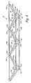
- FIG. 4 is a magnified perspective view of a truss of the first embodiment of the solar tracker.
- FIG. 5 is a magnified rear view of the first embodiment of the solar array with the truss mounted on the solar tracker.
- FIG. 6 is a perspective view of the first embodiment of the solar tracker in a stowed position.
- FIG. 7 is a perspective view of a second embodiment of the solar tracker in a raised position.
- FIG. 8A is a partial magnified view of the second embodiment of the solar tracker.
- FIG. 8B is a partial rear view of the second embodiment of the solar tracker.
- FIG. 9 is a perspective view of the second embodiment of the solar tracker in a stowed position.
- FIGS. 1A and 1B show a front view and a side view, respectively, of a first embodiment of two-axis solar tracker 10 in a raised position and will be discussed in conjunction with one another.
- Solar tracker 10 generally includes solar array 12 consisting of multiple panels, frame 14 , truss 16 , base 18 , leg mount 20 , first actuator 22 , and second actuator 24 .
- Truss 16 is a stiff, lightweight, and cost-effective support for solar array 12 and is pivotable relative to frame 14 and base 18 .
- solar tracker 10 is pivotable between a raised position and a stowed position.
- Solar tracker 10 with truss 16 has increased wind load resistance and is adaptable to various building structures while using conventional linear actuators.
- Solar tracker 10 is designed to align solar array 12 with respect to the sun so that it collects the maximum amount of solar energy. Solar energy is absorbed into solar array 12 where it is subsequently converted to useable energy. Solar array 12 absorbs the maximum amount of solar energy when solar array 12 is aligned normal to the rays of the sun. Solar array 12 is thus mounted to solar tracker 10 , which continually positions solar array 12 relative to the position of the sun.
- solar array 12 can be formed from a plurality of smaller solar panels that are positioned proximate one another to form a large solar array. This allows solar array 12 to capture more sunlight.
- the smaller solar panels are positioned relative to one another to form a diamond shaped array in order to provide less deflection as well as corner-to-corner support.
- Truss 16 is mounted to frame 14 about an azimuthal axis A and is pivotally connected to base 18 about an elevation axis E.
- the triangular shape of truss 16 provides increased wind load resistance for solar tracker 10 .
- Truss 16 is formed from a plurality of truss sections 26 held together by a plurality of tubes 28 .
- truss 16 is formed of a lightweight material, such as aluminum.
- truss 16 can be molded from a glass reinforced nylon or other thermoplastic.
- Base 18 connects solar array 12 to leg mount 20 and generally includes first leg 30 , second leg 32 , and actuator mount 34 .
- First and second legs 30 , 32 of base 18 spread the load of solar tracker 10 .
- Actuator mount 34 is mounted to base 18 and pivotally connects truss 16 to base 18 so that solar array 12 can follow the elevation of the sun about elevation axis E, as well as pivot between a raised position and a stowed position.
- Leg mount 20 generally includes horizontal first and second supports 36 , 38 that connect base 18 to leg mount 20 . Both first and second supports 36 , 38 have attachment posts 40 that allow installation of solar tracker 10 onto a building structure.
- First and second actuators 22 , 24 provide two-axis tracking of solar tracker 10 .
- First actuator 22 controls azimuthal movement of solar array 12 and second actuator 24 controls elevational movement of solar array 12 .
- first and second actuators 22 , 24 are linear actuators.
- FIG. 2 shows a rear view of solar tracker 10 with truss 16 mounted on frame 14 .
- Frame 14 is mounted to the back of solar array 12 and extends across two dimensions of solar array 12 .
- Frame 14 is formed from a plurality of supports 14 a , 14 b positioned relative to one another to form an array. If solar array 12 is formed from a plurality of smaller solar panels, frame 14 also maintains the plurality of smaller solar panels in position relative to one another.
- Truss 16 is attached to frame 14 and in combination with first and second actuators 22 , 24 , controls the alignment of solar array 12 relative to the sun.
- FIG. 2 depicts plurality of supports 14 a , 14 b positioned at intersecting right angles, supports 14 a , 14 b can be formed in any type of array as long as frame 14 can support truss 16 and maintain smaller solar panels relative to one another.
- Truss 16 is mounted to frame 14 and connects solar array 12 to base 18 .
- Truss 16 is formed from a plurality of truss sections 26 a , 26 b , 26 c , 26 d , 26 e , 26 f (collectively truss sections 26 ) held together by first tube 28 a , second tube 28 b , and third tube 28 c (collectively tubes 28 ).
- First tube 28 a pivotally connects truss 16 to frame 14 at frame pivot joints 42 which defines azimuth axis A and allows truss 16 to support solar array 12 .
- Truss 16 is also pivotally connected to base 18 by actuator mount 34 at base pivot joint 44 in order to continually align solar array 12 with respect to the sun about the elevation axis E.
- First leg 30 of base 18 has a first end 30 a , a second end 30 b , and a central portion 30 c .
- First end 30 a and second end 30 b are spaced apart from each other and are connected by central portion 30 c .
- second leg 32 of base 18 has a first end 32 a , a second end 32 b , and a central portion 32 c .
- First end 32 a and second end 32 b are also spaced apart from each other and are connected by central portion 32 c .
- First and second legs 30 and 32 are connected to each other at central portions 30 c , 32 c with first ends 30 a , 32 a of first and second legs 30 , 32 spaced apart from each other in a V-shape and second ends 30 b , 32 b of first and second legs 30 , 32 spaced apart from each other in a V-shape.
- Actuator mount 34 is mounted to base 18 where central portions 30 c , 32 c of first and second legs 30 , 32 are connected.
- First and second supports 36 , 38 of leg mount 20 stabilize base 18 and solar array 12 .
- First support 36 has a first end 36 a and a second end 36 b and second support 38 has a first end 38 a and a second end 38 b .
- First ends 30 a , 32 a of first and second legs 30 , 32 are attached to first support 36 between first and second ends 36 a , 36 b of first support 36 .
- Second ends 30 b , 32 b of first and second legs 30 , 32 are attached to second support 38 between first and second ends 38 a , 38 b of second support 38 .
- First and second supports 36 , 38 have attachment posts 40 a , 40 b , 40 c , 40 d (collectively attachment posts 40 ) located at each of first and second ends 36 a , 36 b and 38 a , 38 b that allow installation of solar tracker 10 onto a building structure.
- FIG. 2 depicts leg mount 20 as having first and second supports 36 , 38 , solar panel 12 may be mounted on any support known in the art.
- FIG. 2 depicts attachment posts 40 as four separate posts, any means known in the art for mounting a device onto a structure can be used to mount solar tracker 10 to the building structure.
- FIG. 3 shows a magnified partial top and rear view of solar array 12 with base 18 removed.
- First actuator 22 has a first end 22 a pivotally connected to truss 16 at a first pivot joint 46 of a connector 48 positioned between second tube 28 b and third tube 28 c , and a second end 22 b pivotally connected to frame 14 at pivot joint 50 .
- First actuator 22 thus pivots solar array 12 about axis A defined by first tube 28 a of truss 16 as first actuator 22 telescopes in and out, controlling movement of solar array 12 in an azimuthal direction.
- First tube 28 a therefore defines the azimuthal axis A for azimuthal movement of solar tracker 10 .
- Second actuator 24 has a first end 24 a pivotally connected to truss 16 at a second pivot joint 52 of connector 48 positioned between second tube 28 b and third tube 28 c , and a middle portion 24 b pivotally connected to actuator mount 34 by pivot joint 54 .
- Second actuator 24 thus pivots solar array 12 about axis E defined by base pivot joint 44 as second actuator 22 telescopes in and out, controlling movement of solar array 12 in an elevational direction.
- Base 18 (through pivot joint 44 ) therefore defines the elevation axis E for elevational movement of solar tracker 10 .
- First pivot joint 46 is generally transverse to second pivot joint 52
- FIG. 4 shows a magnified perspective view of truss 16 .
- Each of first, second, third, fourth, fifth, and sixth truss sections 26 a , 26 b , 26 c , 26 d , 26 e , 26 f (collectively, truss sections 26 ) has a first side 56 , a second side 58 , and a third side 60 that together form a triangular shape.
- First, second, and third pivot holes 62 a , 62 b , 62 c are located between first, second, and third sides 56 , 58 , 60 and are sized to accept tubes 28 .
- First pivot hole 62 a is located between first and second sides 26 a , 26 b
- second pivot hole 62 b is located between second and third sides 26 b , 26 c
- third pivot hole 62 c is located between third and first sides 26 c , 26 a.
- truss sections 26 are sliced at an angle from a truss extrusion and are subsequently assembled together with tubes 28 .
- First and second truss sections 26 a , 26 b are first aligned so that second pivot hole 62 b of first truss section 26 a abuts third pivot hole 62 c of second truss section 26 b and third pivot hole 62 c of first truss section 26 a abuts second pivot hole 62 b of second truss section 26 b .
- first pivot holes 62 a of first and second truss sections 26 a , 26 b are spaced apart.
- Third truss section 26 c is then aligned with second truss section 26 b such that first pivot holes 62 a of second and third truss sections 26 b and 26 c are proximate each other but second and third pivot holes 62 b , 62 c are spaced apart. This pattern is repeated for the length of truss 16 .
- first tube 28 a is passed through first pivot holes 62 a of truss sections 26 .
- Second and third tubes 28 b , 28 c are then passed through alternating second and third pivot holes 62 b , 62 c of truss sections 26 on either side of truss 16 .
- tubes 28 are positioned within pivot holes 62 of truss sections 26 , truss 16 is held together using epoxy.
- Other adhesive means or mechanical fasteners known in the art may also be used to hold truss 16 as a single unit.
- truss 16 allows truss sections 26 to be spaced apart, resulting in increased resistance to side loads imparted to solar array 12 due to wind loading.
- FIG. 4 depicts truss 16 as having six truss sections 26 a - 26 f forming truss 16
- truss 16 may include as many truss sections as necessary to support solar array 12 .
- FIG. 5 shows a magnified back view of solar array 12 with truss 16 mounted to frame 14 .
- truss 16 is mounted to frame 14 at intermediate points along first tube 28 a .
- First tube 28 a is connected to frame 14 by frame pivot joints 42 of frame 14 between first pivot holes 60 a .
- FIG. 5 depicts truss 16 as extending diagonally across diamond-shaped solar array 12 , truss 16 may also extend down the center of the array, similar to a conventional tracking array. Positioning truss 16 diagonally across solar array 12 provides the maximum amount of support to solar array 12 .
- FIG. 6 shows solar tracker 10 in a stowed position.
- solar tracker 10 can be in either a raised position (shown in FIGS. 1A , 1 B, and 2 ) or a stowed position.
- solar tracker 10 is in the raised position so that solar array 12 can capture as much sunlight as possible.
- second actuator 24 retracts and pivots at pivot joint 54 to cause solar array 12 to pivot about pivot joint 44 of actuator mount 34 .
- Solar array 12 pivots about pivot joint 44 until solar array 12 is substantially parallel to the ground.
- Truss 16 is capable of withstanding side load resistance and maintains solar array 12 stable relative to base 18 and leg mount 20 . In the stowed position, solar tracker 10 is better shielded from extreme weather conditions and flying debris that may damage solar array 12 .
- solar array 12 includes a wind sensor and controller that align solar array 12 with the wind in order to minimize the wind loading of solar tracker 10 .
- FIG. 7 shows a perspective view of a second embodiment of solar tracker 100 in a raised position.
- Solar tracker 100 generally includes solar array 102 , frame 104 , first linkage arm 106 , second linkage arm 108 , first actuator 110 , second actuator 112 , and leg mounts 114 a - 114 d .
- Linkage arms 106 , 108 of solar tracker 100 allow solar array 102 to be moved into a stowed position during high winds.
- Solar array 102 of solar tracker 100 functions in the same manner as solar array 12 of solar tracker 10 .
- solar tracker 100 is also pivotable between a raised position and a stowed position, uses conventional linear actuators, and is adaptable to various building structures.
- Frame 104 is attached to solar array 102 and connects solar array 102 to first and second linkage arms 106 , 108 .
- Frame 104 generally includes horizontal crossbars 104 a and 104 b and pivot frame 116 .
- Pivot frame 116 has a first end 116 a and a second end 116 b .
- First end 116 a of pivot frame 116 is connected to crossbar 104 a of frame 104 by first connector 118 a .
- Second end 116 b of pivot frame 116 is connected to crossbar 104 b of frame 104 by second connector 118 b .
- frame 104 of solar tracker 100 depicts frame 104 of solar tracker 100 as including two crossbars 104 a , 104 b and a single pivot frame 116
- frame 104 can be any structure known in the art that allows pivotal connection of at least one of first and second linkage arms 106 , 108 to solar array 102 .
- First and second linkage arms 106 , 108 are pivotally connected to each other by pivot joint 120 .
- First and second linkage arms 106 , 108 are also connected to frame 104 by first, second, and third connectors 122 a , 122 b , 122 c connected to first linkage arm 106 .
- FIG. 7 depicts two linkage arms 106 , 108 pivotally connected to each other, solar tracker 100 may also be constructed with a scissor-type supporting structure or with a single actuator that provides the lift mechanism without departing from the intended scope of the present invention.
- First and second actuators 110 , 112 provide two-axis tracking of solar tracker 100 .
- First actuator 110 controls azimuthal movement of solar array 102 about azimuthal axis A.
- Second actuator 112 controls elevational movement of solar array 102 about elevation axis E.
- first and second actuators 110 and 112 are linear actuators.
- Leg mounts 114 a - 114 d are pivotally attached to first and second linkage arms 106 , 108 and allow installation of solar tracker 100 to a range of locations, such as an existing roof support beam of a commercial building.
- FIG. 7 depicts leg mounts 114 a - 114 d as four separate attachment structures, any means known in the art for mounting a device onto a structure can be used to mount solar tracker 100 to the building structure.
- FIGS. 8A and 8B show a magnified partial view of solar tracker 100 and a partial rear view of solar tracker 100 , respectively, and will be discussed in conjunction with one another.
- Solar array 102 has been removed in FIGS. 8A and 8B .
- First linkage arm 106 has a first end 106 a , a second end 106 b , and a center point 106 c and includes first and second legs 124 a , 124 b .
- First and second legs 124 a , 124 b are parallel to each other from first end 106 a to center point 106 c .
- first and second legs 124 a , 124 b branch out and extend away from each other to form a triangular shape so that first and second legs 124 a , 124 b are spaced from each other at second end 106 b .
- First and second legs 124 a , 124 b are connected to each other at second section 106 b by crossbar 126 .
- second linkage arm 108 also has a first section 108 a , a second section 108 b , and an intermediate section 108 c and includes first and second legs 128 a , 128 b .
- First and second legs 128 a , 128 b extend away from each other slightly from first section 108 a to the intermediate section 108 c .
- First and second legs 128 a , 128 b are connected to each other at intermediate section 108 c by intermediate crossbar 130 .
- Pivot joint 132 at intermediate section 108 c facilitates elevational movement of solar tracker 100 about elevation axis E.
- first and second legs 128 a , 128 b branch out and extend away from each other to form a triangular shape so that first and second legs 128 a , 128 b are spaced from each other at second section 108 b .
- First and second legs 128 a , 128 b are connected to each other by stabilizing crossbar 134 .
- First actuator 110 has a first end 110 a and a middle portion 110 b .
- First end 110 a of first actuator 110 is pivotally connected to solar array 102 at pivot joint 136 and middle portion 110 b of first actuator 110 is pivotally attached to frame 104 by pivot joint 138 .
- First actuator 110 thus pivots solar array 102 about pivot frame 116 as first actuator 110 telescopes in and out, to control movement of solar array 102 in an azimuthal direction about azimuthal axis A.
- Pivot frame 116 therefore defines the azimuthal axis A for azimuthal movement of solar tracker 100 .
- Second actuator 112 has a first rod 112 a and a middle cylinder 112 b .
- First rod 112 a of second actuator 112 is pivotally connected to second linkage arm 108 at intermediate crossbar 130 by pivot 140 .
- Middle cylinder 112 b of second actuator 112 is pivotally attached to stabilizing crossbar 134 by pivot joint 142 .
- first linkage arm 106 pivots about first and second leg mounts 114 a and 114 b
- first and second leg mounts 114 a , 114 b The connection of first and second leg mounts 114 a , 114 b to second linkage arm 106 therefore defines a pivot axis for elevational movement of solar tracker 100 .
- first and second actuators 110 and 112 are linear actuators.
- Leg mounts 114 a , 114 b are pivotally attached to first and second legs 124 a , 124 b of first linkage arm 106 , respectively, at second section 106 b of first linkage arm 106 .
- Leg mounts 114 c and 114 d are pivotally attached to first and second legs 128 a and 128 b of second linkage arm 108 , respectively, at second section 108 b of second linkage arm 108 .
- Pivot joints 144 pivotally connect leg mounts 114 a - 114 d to first and second linkage arms 106 , 108 .
- FIG. 9 shows a perspective view solar tracker 100 in a stowed position. Similar to solar tracker 10 , solar tracker 100 can be in either a raised position ( FIG. 7 ) or a stowed position.
- second actuator 112 telescopes in and pivots second linkage arm 108 at pivot joints 132 so that the intermediate section 108 c of second linkage arm 108 moves toward the ground.
- second section 108 b of second linkage arm 108 also pivots about third and fourth leg mounts 114 c , 114 d , which are attached to the ground.
- First section 108 a of second linkage arm 108 also moves toward the ground as second linkage arm 108 pivots at pivot joint 132 and the intermediate section 108 c lowers. This downward movement of second linkage arm 108 causes first end 106 a of first linkage arm 106 to pivot about pivot joints 120 and also move toward the ground, with solar array 102 . As first end 106 a of first linkage arm 106 moves toward the ground, second section 106 b of first linkage arm 106 pivots about first and second leg mounts 114 a , 114 b until solar tracker 100 is in the fully stowed position. In the stowed position, solar tracker 100 is low to the ground and thus better shielded from extreme weather conditions and flying debris that may damage solar array 102 .
- the solar tracker of the present invention is capable of withstanding extreme weather conditions and being moveable between a raised position and a stowed position. During normal operation, the solar tracker is in the raised position to capture a maximum amount of sunlight. During extreme weather, such as high winds, the solar tracker can retract the solar array into a stowed position. Two linear actuators control the elevational and azimuthal movement of the solar tracker in order to align a solar array with the sun during the day and to move the solar tracker between the raised and stowed positions. The solar tracker also spreads the load of the solar array such that the solar tracker can be mounted on a building structure.
- the solar array of the solar tracker is supported by a truss.
- the truss is designed to provide the solar tracker with increased side load resistance and is formed from a plurality of triangular truss sections that are connected to each other by a plurality of tubes.
- the solar tracker includes a first and a second linkage arm that are pivotally connected to each other and to the solar array. The second linkage arm is also pivotable at a center point of the linkage arm to allow the solar tracker to retract toward the ground.
Abstract
Description
Claims (25)
Priority Applications (3)
| Application Number | Priority Date | Filing Date | Title |
|---|---|---|---|
| US11/376,849 US7884279B2 (en) | 2006-03-16 | 2006-03-16 | Solar tracker |
| CN2007800178110A CN101454619B (en) | 2006-03-16 | 2007-03-12 | Solar tracker |
| PCT/US2007/006151 WO2007108976A2 (en) | 2006-03-16 | 2007-03-12 | Solar tracker |
Applications Claiming Priority (1)
| Application Number | Priority Date | Filing Date | Title |
|---|---|---|---|
| US11/376,849 US7884279B2 (en) | 2006-03-16 | 2006-03-16 | Solar tracker |
Publications (2)
| Publication Number | Publication Date |
|---|---|
| US20070215199A1 US20070215199A1 (en) | 2007-09-20 |
| US7884279B2 true US7884279B2 (en) | 2011-02-08 |
Family
ID=38516507
Family Applications (1)
| Application Number | Title | Priority Date | Filing Date |
|---|---|---|---|
| US11/376,849 Expired - Fee Related US7884279B2 (en) | 2006-03-16 | 2006-03-16 | Solar tracker |
Country Status (3)
| Country | Link |
|---|---|
| US (1) | US7884279B2 (en) |
| CN (1) | CN101454619B (en) |
| WO (1) | WO2007108976A2 (en) |
Cited By (29)
| Publication number | Priority date | Publication date | Assignee | Title |
|---|---|---|---|---|
| US20090250052A1 (en) * | 2007-11-12 | 2009-10-08 | Luz Ii Ltd. | Solar receiver with energy flux measurement and control |
| US20090309568A1 (en) * | 2008-06-17 | 2009-12-17 | Nec Electronics Corporation | Power supply circuit and control method of the same |
| US20100006087A1 (en) * | 2008-07-10 | 2010-01-14 | Brightsource Industries (Israel) Ltd. | Systems and methods for control of a solar power tower using infrared thermography |
| US20100024861A1 (en) * | 2006-10-09 | 2010-02-04 | Cabanillas Ingenieros, S.L. | Dual-Axis Solar Tracker |
| US20100139644A1 (en) * | 2008-10-29 | 2010-06-10 | Brightsource Industries (Israel), Ltd. | Heliostat calibration |
| US20100191378A1 (en) * | 2007-03-26 | 2010-07-29 | Brightsource Industries (Israel) Ltd. | Distributed power towers with differentiated functionalities |
| US20100236239A1 (en) * | 2007-06-11 | 2010-09-23 | Brightsource Industries (Israel) Ltd. | Solar receiver |
| US20100282242A1 (en) * | 2007-11-12 | 2010-11-11 | Brightsource Industries (Israel) Ltd. | Solar power tower system operation and control |
| US20100300510A1 (en) * | 2007-07-23 | 2010-12-02 | Brightsource Industries (Israel), Ltd. | Solar energy systems with reflecting and photovoltaic conversion means |
| US20110036343A1 (en) * | 2008-02-14 | 2011-02-17 | Brightsource Industries (Israel) Ltd. | Devices, methods, and systems for control of heliostats |
| US20110088396A1 (en) * | 2009-10-15 | 2011-04-21 | Brightsource Industries (Israel), Ltd. | Method and system for operating a solar steam system |
| US20110121144A1 (en) * | 2008-08-01 | 2011-05-26 | Vicente Berbegal Pastor | Solar tracker |
| US20110132353A1 (en) * | 2009-12-04 | 2011-06-09 | SunPOD,S INC. | Transportable multi-configurable self-ballasted modular solar power unit |
| US20110220091A1 (en) * | 2010-01-20 | 2011-09-15 | Brightsource Industries (Israel), Ltd. | Method and apparatus for operating a solar energy system to account for cloud shading |
| US20120006317A1 (en) * | 2010-07-06 | 2012-01-12 | Rovshan Sade | Solar Tracker |
| US8210162B2 (en) | 2009-05-04 | 2012-07-03 | Douglas Evan Simmers | Tracking device with weathervaning wind stowage mode of operation |
| US20120192422A1 (en) * | 2009-10-07 | 2012-08-02 | Exosun | Method for embedding a solar structure |
| US20130345886A1 (en) * | 2012-06-20 | 2013-12-26 | General Electric Company | Concentrated solar power system |
| US9003795B2 (en) | 2009-11-24 | 2015-04-14 | Brightsource Industries (Israel) Ltd. | Method and apparatus for operating a solar steam system |
| US9093587B2 (en) | 2012-04-18 | 2015-07-28 | Santa Clara University | Two-axis solar tracker design for low cost deployment and profile for reduced loading moments |
| US9201228B1 (en) * | 2013-02-27 | 2015-12-01 | Focal Technologies, Inc. | Light processing system |
| US9222702B2 (en) | 2011-12-01 | 2015-12-29 | Brightsource Industries (Israel) Ltd. | Systems and methods for control and calibration of a solar power tower system |
| US9249785B2 (en) | 2012-01-31 | 2016-02-02 | Brightsource Industries (Isreal) Ltd. | Method and system for operating a solar steam system during reduced-insolation events |
| US9471050B2 (en) | 2013-01-15 | 2016-10-18 | Wovn, Inc. | Solar tracker and related methods, devices, and systems |
| US9490384B1 (en) | 2009-04-22 | 2016-11-08 | Michael Strahm | Transportable solar power system |
| US20190052224A1 (en) * | 2017-07-18 | 2019-02-14 | Magna Closures Inc. | Solar panel support and drive system |
| US10727782B2 (en) | 2015-05-12 | 2020-07-28 | Dennis Peet | Schedule-based sun tracker for increasing directness of sun exposure upon a solar panel to improve energy production |
| US11444570B2 (en) | 2020-02-28 | 2022-09-13 | OffGrid Power Solutions, LLC | Modular solar skid with enclosures |
| US20220316762A1 (en) * | 2017-06-26 | 2022-10-06 | Unirac Inc. | Multi-level Mounting System |
Families Citing this family (63)
| Publication number | Priority date | Publication date | Assignee | Title |
|---|---|---|---|---|
| US20100095955A1 (en) * | 2006-12-29 | 2010-04-22 | Carlos Maria Carrasco Martinez | Bidirectional solar tracker |
| US7612285B2 (en) * | 2007-01-08 | 2009-11-03 | Edtek, Inc. | Conversion of solar energy to electrical and/or heat energy |
| US8378280B2 (en) | 2007-06-06 | 2013-02-19 | Areva Solar, Inc. | Integrated solar energy receiver-storage unit |
| US8739512B2 (en) | 2007-06-06 | 2014-06-03 | Areva Solar, Inc. | Combined cycle power plant |
| US20090032090A1 (en) * | 2007-07-30 | 2009-02-05 | Emcore Corporation | Method for assembling a terrestrial solar array including a rigid support frame |
| US7381886B1 (en) * | 2007-07-30 | 2008-06-03 | Emcore Corporation | Terrestrial solar array |
| US9022020B2 (en) | 2007-08-27 | 2015-05-05 | Areva Solar, Inc. | Linear Fresnel solar arrays and drives therefor |
| US20090056699A1 (en) | 2007-08-27 | 2009-03-05 | Mills David R | Linear fresnel solar arrays and receievers therefor |
| ITAQ20080009A1 (en) * | 2008-06-12 | 2009-12-13 | Yoav Banin | SECONDARY SYSTEM OF IMPLEMENTATION FOR PRECISION POINTING, MOUNTED ON A TRACKER FOR SOLAR CONCENTRATION SYSTEMS, ABLE TO CARRY SPACE ROTATIONS IN ORDER TO ENSURE ALIGNMENT WITH THE SOLAR SPOKES OF THE CONCENTRATOR OR GROUPS OF |
| US8513514B2 (en) | 2008-10-24 | 2013-08-20 | Suncore Photovoltaics, Inc. | Solar tracking for terrestrial solar arrays with variable start and stop positions |
| US20090293861A1 (en) * | 2008-06-02 | 2009-12-03 | Pvxworks, Llc | Solar tracker system and method of making |
| US20100263659A9 (en) * | 2008-06-02 | 2010-10-21 | Pv Trackers, Llc | Solar tracker system and method of making |
| WO2010022027A2 (en) * | 2008-08-18 | 2010-02-25 | Pratt & Whitney Rocketdyne, Inc. | Heliostat joint |
| IT1391915B1 (en) * | 2008-09-19 | 2012-02-02 | Czaloun | TRACKER DEVICE TO ORIENT MANIFOLDS, ABSORBERS, REFLECTORS, CONCENTRATORS OR PHOTOVOLTAIC MODULES ACCORDING TO THE POSITION OF THE SUN. |
| US8469022B2 (en) * | 2008-09-23 | 2013-06-25 | Jody L. COWAN | Solar panel adjustment mechanism |
| DE102008053605A1 (en) * | 2008-10-17 | 2010-04-29 | Ammersee Solar Gmbh | generator car |
| US8507837B2 (en) * | 2008-10-24 | 2013-08-13 | Suncore Photovoltaics, Inc. | Techniques for monitoring solar array performance and applications thereof |
| CN201319572Y (en) * | 2008-12-18 | 2009-09-30 | 泰通(泰州)工业有限公司 | Photovoltaic generating unit automatically tracking the sun |
| US8188414B2 (en) * | 2008-12-23 | 2012-05-29 | Opel, Inc. | Grid support system for a tracker-mounted solar panel array for rooftop applications |
| TWI367315B (en) * | 2009-03-03 | 2012-07-01 | Univ Nat Taiwan | High efficiency solar tracker designed by the focus track way with array type |
| EP2404124A4 (en) * | 2009-03-05 | 2017-01-25 | Pascal Guillemette | Method and system for optimizing and protecting solar panels |
| WO2010129087A2 (en) * | 2009-05-08 | 2010-11-11 | Sunpower Corporation | Photovoltaic solar collection and tracking system |
| US20100294265A1 (en) * | 2009-05-20 | 2010-11-25 | Zomeworks | Dual axis support for high wind solar panels |
| US20120180846A1 (en) * | 2009-08-21 | 2012-07-19 | Indra Sistemas, S.A. | Solar tracker for the orientation of solar panels |
| EP2293378A1 (en) | 2009-08-24 | 2011-03-09 | Jürgen Zimmermann | Device with orientable parabolic dish |
| US20110043433A1 (en) * | 2009-08-24 | 2011-02-24 | Jurgen Zimmermann | Positioning equipment for aligning a device |
| ES2372688B1 (en) * | 2009-09-17 | 2013-01-24 | Provif Energías Renovables, S.A. | SOLAR FOLLOWER FOR ROOFING OF BUILDINGS. |
| US20120222372A1 (en) * | 2009-11-18 | 2012-09-06 | Hilber Franz | Adjusting device of a stationary photovoltaic system |
| US8490619B2 (en) | 2009-11-20 | 2013-07-23 | International Business Machines Corporation | Solar energy alignment and collection system |
| US8026439B2 (en) * | 2009-11-20 | 2011-09-27 | International Business Machines Corporation | Solar concentration system |
| US8455755B2 (en) * | 2009-12-07 | 2013-06-04 | Electrotherm | Concentrated photovoltaic and thermal solar energy collector |
| US9240510B2 (en) * | 2009-12-07 | 2016-01-19 | Electrotherm, Inc. | Concentrated photovoltaic and thermal solar energy collector |
| CN101783619B (en) * | 2009-12-14 | 2011-11-16 | 干布太阳能股份有限公司 | Solar energy sun-following device structure |
| US9127859B2 (en) * | 2010-01-13 | 2015-09-08 | International Business Machines Corporation | Multi-point cooling system for a solar concentrator |
| CN101826823B (en) * | 2010-01-29 | 2012-03-28 | 中国科学院广州能源研究所 | Thermoelectric-conversion solar thermal power generation system |
| CA2712036A1 (en) * | 2010-07-05 | 2012-01-05 | George G. Lessard | Low profile roof mountable multi axis solar tracker |
| WO2012013827A1 (en) * | 2010-07-28 | 2012-02-02 | Energías Renovables Integrales, S.L. | Folding solar tracker and operating method |
| ITMI20110241A1 (en) * | 2011-02-18 | 2012-08-19 | Integra Renewable En Srl | SOLAR ENERGY CONVERSION PLANT WITH PERFECTED SOLAR TRACKER. |
| US20130037080A1 (en) * | 2011-08-10 | 2013-02-14 | Ron HELFAN | Transportable solar harvester system and method |
| CN102324438B (en) * | 2011-08-18 | 2013-01-23 | 哈尔滨工业大学 | Inflation expansion truss solar panel array capable of on-orbit assembling |
| US20130061845A1 (en) * | 2011-09-12 | 2013-03-14 | Zomeworks Corporation | Radiant energy driven orientation system |
| US8895836B2 (en) * | 2011-10-19 | 2014-11-25 | King Saud University | Dual axis solar tracker apparatus and method |
| US9281777B1 (en) | 2011-11-16 | 2016-03-08 | Charles B. Borgstrom | Solar panel support apparatus |
| CN102589180B (en) * | 2012-02-21 | 2013-10-30 | 浙江恒丰泰减速机制造有限公司 | Intermediate connecting rod mechanism and connecting rod reinforcement rotary positioning mechanism for groove-type thermal power generation system |
| ES2436852B1 (en) * | 2012-05-28 | 2014-10-14 | Abengoa Solar New Technologies, S.A. | SOLAR FOLLOWER WITH AZIMUTAL TURN MECHANISM. |
| US20130334393A1 (en) * | 2012-06-19 | 2013-12-19 | Bruce Sho Umemoto | Dual axis solar array tracker |
| US10720541B2 (en) | 2012-06-26 | 2020-07-21 | Lockheed Martin Corporation | Foldable solar tracking system, assembly and method for assembly, shipping and installation of the same |
| US9496822B2 (en) * | 2012-09-24 | 2016-11-15 | Lockheed Martin Corporation | Hurricane proof solar tracker |
| US9182153B2 (en) | 2012-10-17 | 2015-11-10 | Luanne Moore | Ball bearing tracker assembly |
| CN203325924U (en) * | 2013-05-14 | 2013-12-04 | 比亚迪股份有限公司 | Solar battery assembly support |
| US10495720B2 (en) * | 2014-12-01 | 2019-12-03 | Wts Llc | Control valve assembly for a fluid heating system |
| US11946886B2 (en) * | 2014-12-01 | 2024-04-02 | Wts Llc | Fluid heating system |
| US11255804B2 (en) | 2014-12-01 | 2022-02-22 | Wts Llc | Method of calculating pathogen inactivation for a fluid heating system |
| CN105227055A (en) * | 2015-09-30 | 2016-01-06 | 黑龙江兴安新能源股份有限公司 | A kind of folding and expanding formula solar power plant with function of fascinating |
| JP6263209B2 (en) * | 2016-02-22 | 2018-01-17 | 株式会社ジェンク | Variable angle solar power generation system |
| CN209588428U (en) | 2016-04-29 | 2019-11-05 | 海利奥斯丽特公司 | Photovoltaic solar tracking system |
| PE20191072A1 (en) | 2016-11-18 | 2019-08-16 | Wts Llc | DIGITAL FLUID HEATING SYSTEM |
| BR112019018248A2 (en) * | 2017-03-02 | 2020-06-23 | Array Technologies, Inc. | SPRING COUNTERBALANCE SETS AND SOLAR TRACKERS INCORPORATING SPRING COUNTERBALANCE SETS |
| EP3471265B1 (en) * | 2017-10-10 | 2020-04-29 | CEP-IP Ltd | Deployable solar tracker system |
| CN107943113B (en) * | 2017-11-24 | 2021-03-30 | 山东科技大学 | Foldable solar energy auto-tracing device |
| US11114975B2 (en) | 2018-05-21 | 2021-09-07 | Varun SACHAR | Solar tracking system |
| US11121671B2 (en) * | 2018-09-05 | 2021-09-14 | Ojjo, Inc. | A-frame foundation system for single-axis trackers with weak axis support |
| AU2021340899A1 (en) * | 2020-09-14 | 2023-04-27 | Nextracker Llc | Support frames for solar trackers |
Citations (23)
| Publication number | Priority date | Publication date | Assignee | Title |
|---|---|---|---|---|
| US4256088A (en) | 1978-09-14 | 1981-03-17 | Acurex Corporation | Solar concentrator utilizing a point focusing solar concentrating panel assembly |
| US4404565A (en) * | 1981-11-18 | 1983-09-13 | Radiation Systems Incorporated | Quickly erectable antenna support structure |
| FR2535033A1 (en) | 1982-10-25 | 1984-04-27 | Europ Propulsion | Orientable solar collector. |
| CN85203323U (en) | 1985-08-05 | 1986-08-20 | 任华国 | Stepless adjustable steel truss |
| US4830678A (en) | 1987-06-01 | 1989-05-16 | Todorof William J | Liquid-cooled sealed enclosure for concentrator solar cell and secondary lens |
| US4930493A (en) | 1988-05-09 | 1990-06-05 | Sallis Daniel V | Multi-lever rim-drive heliostat |
| US5022929A (en) * | 1989-02-23 | 1991-06-11 | Gallois Montbrun Roger | Solar collector |
| US5269851A (en) | 1991-02-25 | 1993-12-14 | United Solar Technologies, Inc. | Solar energy system |
| US5317145A (en) * | 1991-12-31 | 1994-05-31 | Wattsun Corporation | Radiation source detector and tracker control having a shade pole and radiation responsive surface in the shape of narrow bands |
| US5986203A (en) * | 1996-06-27 | 1999-11-16 | Evergreen Solar, Inc. | Solar cell roof tile and method of forming same |
| US6080927A (en) | 1994-09-15 | 2000-06-27 | Johnson; Colin Francis | Solar concentrator for heat and electricity |
| US6284968B1 (en) * | 2000-06-19 | 2001-09-04 | Joseph Z. Niesyn | Solar-tracking system |
| US20020074034A1 (en) | 2000-11-10 | 2002-06-20 | Tatsuo Fujisaki | Solar power generation system having cooling mechanism |
| US20020121298A1 (en) | 2001-01-15 | 2002-09-05 | Konold Annemarie Hvistendahl | Combined solar electric power and liquid heat transfer collector panel |
| US20030070705A1 (en) | 2001-10-11 | 2003-04-17 | Hayden Herbert T. | Structure for supporting a photovoltaic module in a solar energy collection system |
| US6662801B2 (en) * | 2001-10-02 | 2003-12-16 | Pinnacle West Capital Corporation | Celestial tracking apparatus and method of controlling wind stow therefor |
| US20040025931A1 (en) | 2002-08-09 | 2004-02-12 | S.I.E.M. S.R.L. | Solar panel for simultaneous generation of electric and thermal energy |
| US20040055631A1 (en) | 2002-05-28 | 2004-03-25 | Kazimierz Szymocha | Hybrid solar energy collector |
| WO2004070281A1 (en) | 2003-02-05 | 2004-08-19 | Panel Ip Pty. Ltd. | Solar energy system |
| US6780365B2 (en) * | 2001-02-13 | 2004-08-24 | Bayer Aktiengesellschaft | Process for preparing composite molded articles by multicomponent injection molding |
| WO2004099682A2 (en) | 2003-05-12 | 2004-11-18 | Ramot At Tel Aviv University Ltd. | Small-scale, concentrating, solar chp system |
| US20050081908A1 (en) | 2003-03-19 | 2005-04-21 | Stewart Roger G. | Method and apparatus for generation of electrical power from solar energy |
| US20050133082A1 (en) | 2003-12-20 | 2005-06-23 | Konold Annemarie H. | Integrated solar energy roofing construction panel |
Family Cites Families (1)
| Publication number | Priority date | Publication date | Assignee | Title |
|---|---|---|---|---|
| EP1272640A2 (en) * | 2000-03-24 | 2003-01-08 | Millennium Pharmaceuticals, Inc. | 3714, 16742, 23546, and 13887 novel protein kinase molecules and uses therefor |
-
2006
- 2006-03-16 US US11/376,849 patent/US7884279B2/en not_active Expired - Fee Related
-
2007
- 2007-03-12 WO PCT/US2007/006151 patent/WO2007108976A2/en active Application Filing
- 2007-03-12 CN CN2007800178110A patent/CN101454619B/en not_active Expired - Fee Related
Patent Citations (24)
| Publication number | Priority date | Publication date | Assignee | Title |
|---|---|---|---|---|
| US4256088A (en) | 1978-09-14 | 1981-03-17 | Acurex Corporation | Solar concentrator utilizing a point focusing solar concentrating panel assembly |
| US4404565A (en) * | 1981-11-18 | 1983-09-13 | Radiation Systems Incorporated | Quickly erectable antenna support structure |
| FR2535033A1 (en) | 1982-10-25 | 1984-04-27 | Europ Propulsion | Orientable solar collector. |
| CN85203323U (en) | 1985-08-05 | 1986-08-20 | 任华国 | Stepless adjustable steel truss |
| US4830678A (en) | 1987-06-01 | 1989-05-16 | Todorof William J | Liquid-cooled sealed enclosure for concentrator solar cell and secondary lens |
| US4930493A (en) | 1988-05-09 | 1990-06-05 | Sallis Daniel V | Multi-lever rim-drive heliostat |
| US5022929A (en) * | 1989-02-23 | 1991-06-11 | Gallois Montbrun Roger | Solar collector |
| US5269851A (en) | 1991-02-25 | 1993-12-14 | United Solar Technologies, Inc. | Solar energy system |
| US5317145A (en) * | 1991-12-31 | 1994-05-31 | Wattsun Corporation | Radiation source detector and tracker control having a shade pole and radiation responsive surface in the shape of narrow bands |
| US6080927A (en) | 1994-09-15 | 2000-06-27 | Johnson; Colin Francis | Solar concentrator for heat and electricity |
| US5986203A (en) * | 1996-06-27 | 1999-11-16 | Evergreen Solar, Inc. | Solar cell roof tile and method of forming same |
| US6284968B1 (en) * | 2000-06-19 | 2001-09-04 | Joseph Z. Niesyn | Solar-tracking system |
| US20020074034A1 (en) | 2000-11-10 | 2002-06-20 | Tatsuo Fujisaki | Solar power generation system having cooling mechanism |
| US20020121298A1 (en) | 2001-01-15 | 2002-09-05 | Konold Annemarie Hvistendahl | Combined solar electric power and liquid heat transfer collector panel |
| US6780365B2 (en) * | 2001-02-13 | 2004-08-24 | Bayer Aktiengesellschaft | Process for preparing composite molded articles by multicomponent injection molding |
| US6662801B2 (en) * | 2001-10-02 | 2003-12-16 | Pinnacle West Capital Corporation | Celestial tracking apparatus and method of controlling wind stow therefor |
| WO2004044502A1 (en) | 2001-10-02 | 2004-05-27 | Pinnacle West Capital Corporation | Celestial tracking apparatus and method of controlling wind stow therefor |
| US20030070705A1 (en) | 2001-10-11 | 2003-04-17 | Hayden Herbert T. | Structure for supporting a photovoltaic module in a solar energy collection system |
| US20040055631A1 (en) | 2002-05-28 | 2004-03-25 | Kazimierz Szymocha | Hybrid solar energy collector |
| US20040025931A1 (en) | 2002-08-09 | 2004-02-12 | S.I.E.M. S.R.L. | Solar panel for simultaneous generation of electric and thermal energy |
| WO2004070281A1 (en) | 2003-02-05 | 2004-08-19 | Panel Ip Pty. Ltd. | Solar energy system |
| US20050081908A1 (en) | 2003-03-19 | 2005-04-21 | Stewart Roger G. | Method and apparatus for generation of electrical power from solar energy |
| WO2004099682A2 (en) | 2003-05-12 | 2004-11-18 | Ramot At Tel Aviv University Ltd. | Small-scale, concentrating, solar chp system |
| US20050133082A1 (en) | 2003-12-20 | 2005-06-23 | Konold Annemarie H. | Integrated solar energy roofing construction panel |
Non-Patent Citations (2)
| Title |
|---|
| First Office Action, Chinese Patent Office, Application No. 200780017811.0, mailed Feb. 5, 2010. |
| Website http://www.newwavetruss.com/about.html. |
Cited By (45)
| Publication number | Priority date | Publication date | Assignee | Title |
|---|---|---|---|---|
| US8237098B2 (en) * | 2006-10-09 | 2012-08-07 | Cabanillas Ingenieros, S.L. | Dual-axis solar tracker |
| US20100024861A1 (en) * | 2006-10-09 | 2010-02-04 | Cabanillas Ingenieros, S.L. | Dual-Axis Solar Tracker |
| US20100191378A1 (en) * | 2007-03-26 | 2010-07-29 | Brightsource Industries (Israel) Ltd. | Distributed power towers with differentiated functionalities |
| US20100236239A1 (en) * | 2007-06-11 | 2010-09-23 | Brightsource Industries (Israel) Ltd. | Solar receiver |
| US8544272B2 (en) | 2007-06-11 | 2013-10-01 | Brightsource Industries (Israel) Ltd. | Solar receiver |
| US20100300510A1 (en) * | 2007-07-23 | 2010-12-02 | Brightsource Industries (Israel), Ltd. | Solar energy systems with reflecting and photovoltaic conversion means |
| US20100282242A1 (en) * | 2007-11-12 | 2010-11-11 | Brightsource Industries (Israel) Ltd. | Solar power tower system operation and control |
| US8365718B2 (en) | 2007-11-12 | 2013-02-05 | Brightsource Industries (Israel) Ltd. | Method and control system for operating a solar power tower system |
| US8360051B2 (en) | 2007-11-12 | 2013-01-29 | Brightsource Industries (Israel) Ltd. | Solar receiver with energy flux measurement and control |
| US8327840B2 (en) | 2007-11-12 | 2012-12-11 | Brightsource Industries (Israel) Ltd. | Solar power tower system operation and control |
| US20090250052A1 (en) * | 2007-11-12 | 2009-10-08 | Luz Ii Ltd. | Solar receiver with energy flux measurement and control |
| US8739775B2 (en) | 2008-02-14 | 2014-06-03 | Brightsource Industries (Israel) Ltd. | Devices, methods, and systems for control of heliostats |
| US20110036343A1 (en) * | 2008-02-14 | 2011-02-17 | Brightsource Industries (Israel) Ltd. | Devices, methods, and systems for control of heliostats |
| US20090309568A1 (en) * | 2008-06-17 | 2009-12-17 | Nec Electronics Corporation | Power supply circuit and control method of the same |
| US8931475B2 (en) | 2008-07-10 | 2015-01-13 | Brightsource Industries (Israel) Ltd. | Systems and methods for control of a solar power tower using infrared thermography |
| US20100006087A1 (en) * | 2008-07-10 | 2010-01-14 | Brightsource Industries (Israel) Ltd. | Systems and methods for control of a solar power tower using infrared thermography |
| US20110121144A1 (en) * | 2008-08-01 | 2011-05-26 | Vicente Berbegal Pastor | Solar tracker |
| US20100139644A1 (en) * | 2008-10-29 | 2010-06-10 | Brightsource Industries (Israel), Ltd. | Heliostat calibration |
| US9490384B1 (en) | 2009-04-22 | 2016-11-08 | Michael Strahm | Transportable solar power system |
| US8210162B2 (en) | 2009-05-04 | 2012-07-03 | Douglas Evan Simmers | Tracking device with weathervaning wind stowage mode of operation |
| US8904734B2 (en) * | 2009-10-07 | 2014-12-09 | Exosun | Method for mounting a solar panel support structure by embedding its legs |
| US20120192422A1 (en) * | 2009-10-07 | 2012-08-02 | Exosun | Method for embedding a solar structure |
| US8627664B2 (en) | 2009-10-15 | 2014-01-14 | Brightsource Industries (Israel), Ltd. | Method and system for operating a solar steam system |
| US20110088396A1 (en) * | 2009-10-15 | 2011-04-21 | Brightsource Industries (Israel), Ltd. | Method and system for operating a solar steam system |
| US9003795B2 (en) | 2009-11-24 | 2015-04-14 | Brightsource Industries (Israel) Ltd. | Method and apparatus for operating a solar steam system |
| US20110132353A1 (en) * | 2009-12-04 | 2011-06-09 | SunPOD,S INC. | Transportable multi-configurable self-ballasted modular solar power unit |
| US20110220091A1 (en) * | 2010-01-20 | 2011-09-15 | Brightsource Industries (Israel), Ltd. | Method and apparatus for operating a solar energy system to account for cloud shading |
| US9170033B2 (en) | 2010-01-20 | 2015-10-27 | Brightsource Industries (Israel) Ltd. | Method and apparatus for operating a solar energy system to account for cloud shading |
| US20120006317A1 (en) * | 2010-07-06 | 2012-01-12 | Rovshan Sade | Solar Tracker |
| US9057546B2 (en) * | 2010-07-06 | 2015-06-16 | Rovshan Sade | Solar tracker |
| US9222702B2 (en) | 2011-12-01 | 2015-12-29 | Brightsource Industries (Israel) Ltd. | Systems and methods for control and calibration of a solar power tower system |
| US9249785B2 (en) | 2012-01-31 | 2016-02-02 | Brightsource Industries (Isreal) Ltd. | Method and system for operating a solar steam system during reduced-insolation events |
| US9093587B2 (en) | 2012-04-18 | 2015-07-28 | Santa Clara University | Two-axis solar tracker design for low cost deployment and profile for reduced loading moments |
| US20130345886A1 (en) * | 2012-06-20 | 2013-12-26 | General Electric Company | Concentrated solar power system |
| US9471050B2 (en) | 2013-01-15 | 2016-10-18 | Wovn, Inc. | Solar tracker and related methods, devices, and systems |
| US9488968B2 (en) | 2013-01-15 | 2016-11-08 | Wovn, Inc. | Energy distribution system and related methods, devices, and systems |
| US9435989B1 (en) * | 2013-02-27 | 2016-09-06 | Focal Technologies, Inc. | Light processing system |
| US9201228B1 (en) * | 2013-02-27 | 2015-12-01 | Focal Technologies, Inc. | Light processing system |
| US10727782B2 (en) | 2015-05-12 | 2020-07-28 | Dennis Peet | Schedule-based sun tracker for increasing directness of sun exposure upon a solar panel to improve energy production |
| US20220316762A1 (en) * | 2017-06-26 | 2022-10-06 | Unirac Inc. | Multi-level Mounting System |
| US11774144B2 (en) * | 2017-06-26 | 2023-10-03 | Unirac Inc. | Multi-level mounting system |
| US20190052224A1 (en) * | 2017-07-18 | 2019-02-14 | Magna Closures Inc. | Solar panel support and drive system |
| US11855581B2 (en) * | 2017-07-18 | 2023-12-26 | Polar Racking Inc. | Solar panel support and drive system |
| US11444570B2 (en) | 2020-02-28 | 2022-09-13 | OffGrid Power Solutions, LLC | Modular solar skid with enclosures |
| US11750145B2 (en) | 2020-02-28 | 2023-09-05 | OffGrid Power Solutions, LLC | Modular solar skid with enclosures |
Also Published As
| Publication number | Publication date |
|---|---|
| US20070215199A1 (en) | 2007-09-20 |
| CN101454619A (en) | 2009-06-10 |
| CN101454619B (en) | 2011-08-31 |
| WO2007108976A2 (en) | 2007-09-27 |
| WO2007108976A3 (en) | 2008-11-20 |
| WO2007108976A4 (en) | 2009-01-15 |
Similar Documents
| Publication | Publication Date | Title |
|---|---|---|
| US7884279B2 (en) | Solar tracker | |
| US7647924B2 (en) | System for supporting energy conversion modules | |
| US8100122B2 (en) | Solar roof tracker | |
| US7252083B2 (en) | Structure for supporting energy conversion modules and solar energy collection system | |
| US8941043B2 (en) | Device for driving a light receiving element to track a light source | |
| EP3202029B1 (en) | Portable solar photovoltaic array | |
| US20090050191A1 (en) | System and Method for Solar Tracking | |
| US8119963B2 (en) | High efficiency counterbalanced dual axis solar tracking array frame system | |
| US8188413B2 (en) | Terrestrial concentrator solar tracking photovoltaic array | |
| US8684190B2 (en) | Multi-position solar panel rack | |
| WO2006116398A2 (en) | Solar panel mounting structure | |
| WO2012071404A1 (en) | Solar collector positioning apparatus | |
| US9093587B2 (en) | Two-axis solar tracker design for low cost deployment and profile for reduced loading moments | |
| KR101318888B1 (en) | Linear Sloped Dual Axis Solar Tracker Supported with Two End Truss Columns | |
| CN101939904A (en) | Solar collector stabilized by cables and a compression element | |
| US20120125408A1 (en) | Solar panel racking assembly and system | |
| KR101585593B1 (en) | Structures for solar panel installation | |
| US20130291926A1 (en) | Solar Tracking Apparatus | |
| US20130334393A1 (en) | Dual axis solar array tracker | |
| JP3070637U (en) | Tower type solar generator | |
| WO2020129830A1 (en) | Solar tracking platform system and solar power generation device of solar tracking type | |
| WO2018099601A1 (en) | Solar module array and method of assembling a solar module array | |
| CA2721850A1 (en) | Multi-position solar panel rack | |
| US20120074285A1 (en) | System and kit for adjustably mounting an article | |
| CA2740264A1 (en) | System and kit for adjustably mounting an article |
Legal Events
| Date | Code | Title | Description |
|---|---|---|---|
| AS | Assignment |
Owner name: UNITED TECHNOLOGIES CORPORATION, CONNECTICUT Free format text: ASSIGNMENT OF ASSIGNORS INTEREST;ASSIGNORS:DOLD, ROBERT H.;NIETER, JEFFREY J.;REEL/FRAME:017680/0730 Effective date: 20060307 |
|
| AS | Assignment |
Owner name: WELLS FARGO BANK, NATIONAL ASSOCIATION, NORTH CARO Free format text: SECURITY AGREEMENT;ASSIGNOR:AEROJET-GENERAL CORPORATION;REEL/FRAME:030628/0319 Effective date: 20130614 |
|
| AS | Assignment |
Owner name: U.S. BANK NATIONAL ASSOCIATION, CALIFORNIA Free format text: SECURITY AGREEMENT;ASSIGNOR:AEROJET-GENERAL CORPORATION;REEL/FRAME:030656/0667 Effective date: 20130614 |
|
| AS | Assignment |
Owner name: RPW ACQUISITION LLC, DELAWARE Free format text: ASSIGNMENT OF ASSIGNORS INTEREST;ASSIGNOR:UNITED TECHNOLOGIES CORPORATION;REEL/FRAME:030750/0283 Effective date: 20130614 Owner name: AEROJET ROCKETDYNE, INC., CALIFORNIA Free format text: MERGER/CHANGE OF NAME;ASSIGNOR:RPW ACQUISITION LLC;REEL/FRAME:030754/0248 Effective date: 20130614 |
|
| FPAY | Fee payment |
Year of fee payment: 4 |
|
| AS | Assignment |
Owner name: SOLARRESERVE TECHNOLOGY, LLC, CALIFORNIA Free format text: ASSIGNMENT OF ASSIGNORS INTEREST;ASSIGNOR:AEROJET ROCKETDYNE OF DE;REEL/FRAME:034530/0978 Effective date: 20141009 |
|
| AS | Assignment |
Owner name: AEROJET ROCKETDYNE OF DE, INC., CALIFORNIA Free format text: RELEASE BY SECURED PARTY;ASSIGNOR:U.S. BANK NATIONAL ASSOCIATION;REEL/FRAME:036666/0103 Effective date: 20141021 |
|
| AS | Assignment |
Owner name: AEROJET ROCKETDYNE, INC. (F/K/A AEROJET-GENERAL CO Free format text: RELEASE BY SECURED PARTY;ASSIGNOR:U.S. BANK NATIONAL ASSOCIATION;REEL/FRAME:039594/0887 Effective date: 20160715 |
|
| FEPP | Fee payment procedure |
Free format text: MAINTENANCE FEE REMINDER MAILED (ORIGINAL EVENT CODE: REM.); ENTITY STATUS OF PATENT OWNER: LARGE ENTITY |
|
| LAPS | Lapse for failure to pay maintenance fees |
Free format text: PATENT EXPIRED FOR FAILURE TO PAY MAINTENANCE FEES (ORIGINAL EVENT CODE: EXP.); ENTITY STATUS OF PATENT OWNER: LARGE ENTITY |
|
| STCH | Information on status: patent discontinuation |
Free format text: PATENT EXPIRED DUE TO NONPAYMENT OF MAINTENANCE FEES UNDER 37 CFR 1.362 |
|
| FP | Lapsed due to failure to pay maintenance fee |
Effective date: 20190208 |