US7904932B2 - Wideband node in a CATV network - Google Patents
Wideband node in a CATV network Download PDFInfo
- Publication number
- US7904932B2 US7904932B2 US12/166,972 US16697208A US7904932B2 US 7904932 B2 US7904932 B2 US 7904932B2 US 16697208 A US16697208 A US 16697208A US 7904932 B2 US7904932 B2 US 7904932B2
- Authority
- US
- United States
- Prior art keywords
- signal
- mhz
- band
- frequency
- converted
- Prior art date
- Legal status (The legal status is an assumption and is not a legal conclusion. Google has not performed a legal analysis and makes no representation as to the accuracy of the status listed.)
- Expired - Fee Related
Links
- 238000011144 upstream manufacturing Methods 0.000 claims abstract description 125
- 239000000835 fiber Substances 0.000 claims description 29
- 238000000034 method Methods 0.000 claims description 21
- 238000006243 chemical reaction Methods 0.000 claims description 15
- 230000003287 optical effect Effects 0.000 claims description 13
- 230000005540 biological transmission Effects 0.000 abstract description 13
- 238000001228 spectrum Methods 0.000 abstract description 10
- 238000012546 transfer Methods 0.000 abstract description 5
- 230000006855 networking Effects 0.000 abstract description 3
- 238000000411 transmission spectrum Methods 0.000 description 6
- 238000012545 processing Methods 0.000 description 5
- 239000000284 extract Substances 0.000 description 3
- 238000011143 downstream manufacturing Methods 0.000 description 2
- 238000001914 filtration Methods 0.000 description 2
- 239000013307 optical fiber Substances 0.000 description 2
- 239000004606 Fillers/Extenders Substances 0.000 description 1
- 230000001154 acute effect Effects 0.000 description 1
- 230000002238 attenuated effect Effects 0.000 description 1
- 238000004891 communication Methods 0.000 description 1
- 238000009434 installation Methods 0.000 description 1
- 238000012986 modification Methods 0.000 description 1
- 230000004048 modification Effects 0.000 description 1
- 238000011017 operating method Methods 0.000 description 1
- 238000000926 separation method Methods 0.000 description 1
Images


Classifications
-
- H—ELECTRICITY
- H04—ELECTRIC COMMUNICATION TECHNIQUE
- H04N—PICTORIAL COMMUNICATION, e.g. TELEVISION
- H04N7/00—Television systems
- H04N7/10—Adaptations for transmission by electrical cable
- H04N7/102—Circuits therefor, e.g. noise reducers, equalisers, amplifiers
-
- H—ELECTRICITY
- H04—ELECTRIC COMMUNICATION TECHNIQUE
- H04N—PICTORIAL COMMUNICATION, e.g. TELEVISION
- H04N7/00—Television systems
- H04N7/10—Adaptations for transmission by electrical cable
- H04N7/102—Circuits therefor, e.g. noise reducers, equalisers, amplifiers
- H04N7/104—Switchers or splitters
-
- H—ELECTRICITY
- H04—ELECTRIC COMMUNICATION TECHNIQUE
- H04N—PICTORIAL COMMUNICATION, e.g. TELEVISION
- H04N7/00—Television systems
- H04N7/16—Analogue secrecy systems; Analogue subscription systems
- H04N7/173—Analogue secrecy systems; Analogue subscription systems with two-way working, e.g. subscriber sending a programme selection signal
- H04N7/17309—Transmission or handling of upstream communications
Definitions
- the present invention relates generally to cable television distribution networks. More particularly, the present invention relates to a node in a HFC infrastructure-based CATV network utilized as an advanced interfacing device between the fiber optic segment and the coaxial segment of the CATV infrastructure.
- the fiber optic trunk and the coaxial trunk of the network are connected via specific devices typically referred to as fiber nodes.
- the fiber node receives optical signals from the head-end via fiber optic cables, converting the optical signals to an RF signal and feeding the RF signal to the network subscribers via the coaxial portion which typically includes the distribution and drop cables and associated amplifiers and splitters.
- the fiber node receives an RF signal from subscribers via the coaxial portion of the network, converts the RF signal to optical signals and feeds the optical signals via the fiber optic portion of the network back to the head-end.
- signals transmitted across a standard cable television infrastructure from a head-end to a network subscriber and back from the network subscriber to the head-end, are modulated such as to have a bandwidth with a frequency range of about 5 MHz to about 860 MHz.
- the signals carry diverse encoded information units representing content, services and applications.
- Logically related and physically grouped information units are suitably modulated into distinct specifically allocated transmission channels.
- the channels are distributed across the available frequency range according to a predefined frequency plan.
- the number of potentially available downstream channels from the head-end to the subscriber and upstream channels from the subscriber to the head-end for the subscribers depends directly on the available bandwidth of the signal.
- the currently utilized signal with an about 5 to 860 MHz transmission bandwidth limits the number of available downstream and upstream channels. In many applications the 5-42 MHz portion of the signal is used for upstream transmission and the 50-860 MHz portion of the signal is used for the downstream or forward portion.
- DOCSIS Data Over Cable Services Interface Specification
- MSOs Multi-system Operators
- SMB small and medium businesses
- the transmission spectrum problem is particularly acute in the upstream where out of the about 15 to 42 MHz portion of the signal used less than 20 MHz are usable.
- equipment which is based on the DOCSIS standard, such as the so-called CMTS routers, located in the head-end of the HFC networks is now suitable for broadcast and reception of a signal ranging between about 5-860 MHz.
- the current solution for increasing the upstream capacity involves costly investment as well as only 80 MHz of the 100 MHz available since some of the spectrum is dedicated to common service for all nodes.
- the co-pending related PCT patent application PCT/IL00/00655 describes and teaches a system and method of a CATV network having a bandwidth of about 5 to about 3000 MHz for the transmission of upstream and downstream wideband signals within.
- the CATV network could be a standard coaxial media-based plant or an HFC-infrastructure.
- the system and method proposed by the above-mentioned related patent application involves the installation and/or modification of a set of active and passive components along the signal transport path of the network in order to enable the transmission of a wideband signal with a frequency range of about 5 to 3000 MHz and higher.
- the apparatus comprises the elements of: a triplexer device to separate in an upstream direction the wideband signal into the high frequency band signal and a CATV signal of about 5 to 860 MHz, an amplifier device to amplify the high frequency band signal in the upstream direction, a splitter device to split the amplified high frequency band signal into at least four reproduced signals in the upstream direction, a first frequency converter device to down-convert the first frequency sub-band of the first reproduced signal into a first down-converted signal of about 12 to 42 MHz in the upstream direction, a second frequency converter device to down-convert the second frequency sub-band of the second reproduced signal into a second down-converted signal in the upstream direction, a third frequency converter device to down-convert the third frequency sub-band
- a second aspect of the present invention regards within a hybrid fiber cable signal distribution network, a method for the division, frequency conversion and multiplexing of at least four signal sub-bands included in a high frequency upstream band signal of a combined wideband signal of about 5 to 3000 MHz.
- the method comprises the steps of: separating in an upstream direction the wideband signal into the high frequency band signal and a CATV signal of about 50 to 860 MHz, amplifying the high frequency band signal in the upstream direction, splitting the amplified high frequency band signal into at least four reproduced signals in the upstream direction, down-converting the first frequency sub-band of the first reproduced signal into a first down-converted signal in the upstream direction, down-converting the second frequency sub-band of the second reproduced signal into a second down-converted signal in the upstream direction, down-converting the third frequency sub-band of the third reproduced signal into a third down-converted signal in the upstream direction, down-converting the fourth frequency sub-band of the fourth reproduced signal into a fourth down-converted signal in the upstream direction; and multiplexing the first down-converted signal, the second down-converted signal, the third down-converted signal and the fourth down-converted signal into a combined signal in the upstream direction.
- CATV data protocols and standards such as DOCSIS
- CMTS CMTS
- DOCSIS DOCSIS
- CMTS CMTS
- FIG. 1 is a schematic illustration of a CATV distribution plant, as known in the art
- FIG. 2A is a schematic illustration of the structure of the wideband node device installed in the CATV network, in accordance with a preferred embodiment of the present invention
- FIG. 2B is a schematic illustration of the structure of an alternative extended node device, in accordance with a preferred embodiment of the present invention.
- FIG. 3 shows an exemplary allocation of the transmission spectrum of the wideband signal in the upstream and downstream, in accordance with a preferred embodiment of the present invention
- FIG. 4 shows another exemplary allocation of the transmission spectrum of the wideband signal in the upstream and downstream, in accordance with a preferred embodiment of the present invention.
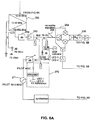
- FIGS. 5A , 5 B, 6 A and 6 B show the detailed exemplary structure of the wideband node device installed in the CATV network, in accordance with a preferred embodiment of the present invention.
- a new and novel node device which enables transmission of a wideband signal consisting of the legacy spectrum of about 5-860 MHz as well as a new downstream spectrum of about 1000-2000 MHz and a new upstream spectrum of about 2000-3000 MHz which enables transfer of data in the upstream direction employing multiple upstream bands without making substantial investment in upstream physical node splitting thus providing networking services to residential subscribers, as well as to small and medium-sized businesses (SMB).
- SMB small and medium-sized businesses
- FIG. 1 illustrates a simplified structure of an existing CATV network.
- Signals from a network head-end 8 are transmitted and received via the fiber trunk section 10 of the network to a conventional CATV node device 12 .
- the head-end may include one or more DOCSIS or other Cable Modem Termination System (CMTS) devices 9 .
- CMTS Cable Modem Termination System
- the CATV node device 12 is connected to network subscribers 32 via one or more ports where each port connected to a distinct distribution coax cable 14 .
- the distribution cable 14 includes one or more line extender amplifiers (LEX) 20 , 26 to maintain the signal levels and several splitters and tap devices 16 , 18 , 22 , 24 , 28 , 30 .
- LEX line extender amplifiers
- the tap devices 28 , 30 are linked via specific drop cables 32 to the Customer Premises Equipment (CPE) of the network subscribers 34 .
- CPE Customer Premises Equipment
- the outlet 40 is connected to a cable modem 42 and a CPE such as a computing device 44 and to Set Top Box 46 connected to CPE such as a television set 48 .
- the transmission path over the cable system can be realized at the head-end by the CMTS 9 and at each subscriber location by a cable modem (not shown).
- CMTS-NSI Cable Modem Termination System-Network-Side Interface
- CMCI cable-modem-to-customer-premises-equipment interface
- the CMTS 9 may be connected to a data network 11 , such as the Internet or other wide or local networks.
- a data network 11 such as the Internet or other wide or local networks.
- the CMTS 9 receives data from the data network 11 .
- the data is modulated by the CMTS 9 to the CMTS downstream RF interface (not shown) and is combined and sent downstream in the 50-860 MHz signal band.
- data is sent from the node 12 via the fiber trunk cable to the head-end 8 in the 5-42 MHz signal band.
- the CMTS upstream RF interface receives the data signal from the upstream splitter (not shown) and demodulates the signal to data signals sent to the data network 11 .
- the CATV node device 12 converts the fiber optic signal into an RF signal to be transmitted downstream on the distribution coax cable 14 .
- the DOCSIS defines the interface requirements for cable modems operative in high-speed data distribution over cable television system networks.
- the current DOCSIS protocol enables the handling of data transmission in the downstream direction at speeds up to about 30 Mbps per 6 MHz channel at quadrature amplitude modulation (QAM) 64 , as well as up to about 10 Mbps per 3.2 MHz channel at QAM 16 for the upstream or return direction.
- the node 12 is the frequency conversion element, which may be implemented by having a multi port hub to interface with a multi port fiber node.
- the apparatus and method proposed by the present invention provide substantially higher upstream data speeds in order to alleviate the problem.
- the downstream signal of between about 100-800 MHz is converted to a first high frequency signal of about 1250-1950 MHz band.
- the fiber node of the present invention further receives the upstream signal carried in a second high frequency signal band of about 2250-2950 MHz band.
- the first and second high frequency signal bands are divided into channels carrying data according to the DOCSIS protocol which can provide up to 100 new 6 MHz channels each carrying 30 Mbps with QAM 64 metrics in the downstream direction, and 100 new 3.2 MHz channels each carrying 10 Mbps with QAM 16 metrics in the upstream direction.
- DOCSIS is a Layer 2 protocol
- Virtual Private Networks may be implemented in association with the present invention in order to replace costly leased line services.
- the node device 200 of the present invention is installed in an HFC infrastructure-based CATV network between the fiber trunk and the distribution cable of the network.
- the node device 200 is connected to at least one distribution line in the downstream and to a fiber node (not shown) in the upstream where the fiber node is connected via the fiber optic lines 84 , 86 to a network head-end 82 .
- the device 200 comprises a triplexer device 74 , an amplifier device 73 , a signal splitter device 76 , at least four frequency conversion devices 78 ′, 78 ′′, 78 ′′′, 78 ′′′′, and a Wavelength Division Multiplexing (WDM) multiplexer device 80 .
- WDM Wavelength Division Multiplexing
- the device 74 receives an upstream wideband signal 72 of about 5 to about 3000 MHz from the distribution segment of the CATV network.
- a node may receive one or more downstream wideband signal from one or more distribution cables. Typically a node will receive 3 distribution cables in the upstream direction.
- the wideband signal 72 is fed to the triplexer device 74 .
- the triplexer device 74 comprises three frequency selective circuits in order to select from the wideband signal 72 three separate frequency bands.
- the CATV frequency selective circuit 74 ′′′ separates the signal 90 of about 5 to about 860 MHz band from the wideband signal.
- the signal 90 carries the standard CATV channels in the downstream and upstream from the network head-end 82 through the fiber node to the network subscribers and vice versa.
- a fiber transceiver 101 converts the RF signal to optic signal in the upstream direction and from the fiber optic to RF signal in the downstream or forward direction.
- the X-High frequency selective circuit 74 ′ separates from the wideband signal 72 a high frequency signal 91 of about 2250 to 3000 MHz band of the wideband signal 72 .
- the separated high frequency signal 91 carries upstream data submitted by the network subscribers in order to be sent to the head-end 82 via an upstream fiber optic trunk 84 .
- the high frequency signal 91 may be divided into about 100 3.2 MHz channels each carrying DOCSIS compliant data at about 10 Mbps in the upstream direction.
- the signal 91 includes at least four frequency sub-bands in between 2250 and 3000 MHz where each sub-band carries 30 MHz of upstream band. The four sub-bands may be collected from one to four different distribution lines.
- the signal 91 includes a first sub-band of an about 2250 to about 2280 MHz frequency range that carries upstream data, a second sub-band of an about 2300 to about 2330 MHz frequency range that carries upstream data, a third sub-band of about 2350 to about 2380 MHz that carries upstream data, and a fourth sub-band of about 2400 to about 2430 MHz that carries upstream data.
- the first, second, third and fourth sub-bands may be received from one to four different distribution lines.
- each sub band may comprise of 9 channels of about 3.2 MHz or 18 channels of about 1.6 MHz carrying data at 10 Mbps and 5 Mbps respectively.
- the signal 91 is fed to the amplifier device 73 and amplified in order to maintain appropriate signal level. Subsequently the amplified signal 91 is fed to a signal splitter device 76 .
- the splitter device 76 splits the signal 91 into at least four identical or near identical reproduced signals 91 ′, 91 ′′, 91 ′′′, and 91 ′′′′.
- the reproduced signals 91 ′, 91 ′′, 91 ′′, 91 ′′′′ are fed into a set of frequency selective block conversion devices 78 ′, 78 ′′, 78 ′′′, 78 ′′′′ respectively.
- the first reproduced signal 91 ′ is down-converted by the frequency conversion device 78 ′ from the about 2250 to 2280 MHz to about 12-42 MHz.
- the second reproduced signal 91 ′′ is down-converted by the frequency conversion device 78 ′′ from the about 2300 to 2330 MHz to about 12-42 MHz.
- the third reproduced signal 91 ′′′ is down-converted by the frequency conversion device 78 ′′′ from the about 2350 to 2380 MHz to about 12-42 MHz.
- the fourth reproduced signal 91 ′′′′ is down-converted by the frequency conversion device 78 ′′′′ from the about 2400 to 2430 MHz to about 12 to 42 MHz.
- the output of the frequency conversion devices the first down-converted signal 78 ′, the second down-converted signal 78 ′′, the third down-converted signal 78 ′′′, and the fourth down-converted signal 78 ′′′′ are four distinct signals at the about 12 to 42 MHz frequency band where each distinct signal carries sub-band and or distribution line-specific upstream data.
- the signals are either converted into optical format by an RF-to-Optical converter (not shown) or converted into digital format by an Analog-to-Digital converter device (not shown).
- the converted signals are fed to a multiplexer device 80 .
- the device 80 could be a Wavelength Division Multiplexing (WDM or DWDM) device or any other multiplexer device in accordance with the network configuration.
- the multiplexer device 80 generates a multiplexed output signal 84 that is transmitted across the trunk segment of the CATV network to the network head-end 82 via an optical transmitter device.
- the multiplexed signal 84 is received by the network head-end 82 .
- the signal is separated into at least four distinct signals 95 ′, 95 ′′, 95 ′′′, 95 ′′′′ and the separated signals are transmitted to separate CMTS ports in order to be suitably handled by the CMTS device 88 .
- the at least four down-converted signals could be converted to optical format by RF-to-Optical converters 104 ′, 104 ′′, 104 ′′′, 104 ′′′′ and fed into at least four separate fiber optic lines 102 ′, 102 ′′, 102 ′′′, 102 ′′′′ that could carry the at least four signals separately to the network head-end 82 via the fiber trunk segment of the CATV network.
- the four optical signals transmitted through the optical fibers 102 ′, 102 ′′, 102 ′′′, 102 ′′′′ are received by the network head-end 82 and are transmitted to separate CMTS ports in order to be suitably handled by the CMTS device 88 .
- a signal carrying data generated through CMTS ports 88 of about 100 to about 800 MHz is transmitted from the head-end 82 to the extended node device 72 via the fiber trunk segment 86 of the CATV network.
- This signal is non-legacy and includes new data and information.
- the signal 86 is suitably converted from optical format to RF analog format via a fiber receiver 100 .
- the signal 86 is then up-converted by the frequency conversion device 93 to signal 92 from the about 150-860 MHz to the about 1250-1950 MHz signal band.
- the X-low frequency selective circuit 74 ′′ combines the low frequency signal 92 of about 1250 MHz to about 1950 MHz to the wideband signal 72 .
- the signal 92 carries a plurality of additional channels in the downstream from the network head-end 82 to network subscribers.
- the low frequency signal 92 may be divided into about 100 6 MHz channels each carrying DOCSIS compliant data at about 30 Mbps per channel in the downstream or forward direction.
- the triplexer device 74 combines the signal 92 with the CATV signal legacy signal 90 into a wideband signal that is transmitted to the distribution lines in the downstream or forward direction.
- the transmission spectrum spans a frequency range of about 5 to 3000 MHz.
- the spectrum includes an about 5 to 42 MHz legacy upstream band 114 , an about 54 to 880 MHz legacy downstream band 116 , an about 1250 to 1950 MHz additional (or extended) downstream band 118 , and an about 2250 to 3000 MHz additional upstream region 120 .
- the legacy region spans a frequency range of about 5 to 860 MHz.
- the legacy upstream band 114 is allocated within the legacy region and carries information units introduced by the network subscribers from the subscribers to the head-end in the upstream.
- the legacy downstream band 116 is allocated within the legacy region and it is utilized to transmit legacy channels from the head-end to the network subscribers in the downstream.
- the additional bandwidth region spans a frequency range of about 1250 to 3000 MHz.
- the additional downstream band 118 is allocated within the additional frequency region, said band is used in the transmission of a plurality of channels from the head-end to the subscribers in the downstream.
- the additional upstream band 120 is allocated to carry information units generated by the subscribers from the subscribers to the head-end in the upstream.
- the upstream band 120 is divided into at least four sub-bands 122 , 124 , 126 , and 128 where each sub-band spans a frequency rage of about 30 MHz.
- the frequency allocation of the sub-bands is as follows: an about 2250 to 2280 MHz sub-band 122 , an about 2300 to 2330 MHz sub-band 124 , an about 2350 to 2380 MHz sub-band 126 , and an about 2400 to 2430 MHz sub-band 128 .
- Each of the sub-bands 122 , 124 , 126 , 128 include about 10 upstream channels assigned for subscriber traffic under the current DOCSIS protocols.
- the bandwidth of each of the upstream channels is about 3 MHz.
- the wideband node extracts the four sub-bands 122 , 124 , 126 , 128 from the additional upstream band 120 . From the extracted sub-bands 122 , 124 , 126 , 128 four separate signals, such as an about 2250 to 2280 MHz signal 130 , about 2300 to 2330 MHz signal 132 , an about 2350 to 3280 MHz signal 134 , and an about 2400 to 2430 MHz signal 136 , are created.
- the signals 130 , 132 , 134 , 136 each has a 30 MHz bandwidth.
- the four signals 130 , 132 , 134 , 136 are down-converted separately to four signals 138 , 140 , 142 , 144 where each of the down-converted signals have the same about 30 MHz bandwidth and the same about 12 to 42 MHz frequency range but carrying different content.
- the wideband node proposed by the present invention can be modified to allow substantially increased upstream data transmission without the need to replace passive elements in upgraded legacy CATV networks if the spectrum used will be confined up to about 1100 MHz.
- the proposed wideband node of FIG. 3 provision is made for about four upstream channels in the 2250 to 3000 MHz frequency range.
- the above mentioned frequency allocation will require the replacement of existing CATV passive elements.
- a frequency range of about 860 MHz to 1100 MHz could be dedicated to the additional upstream data traffic. Still referring to FIG.
- the transmission spectrum includes an about 5 to 42 MHz legacy upstream band 148 , an about 54 to 880 MHz legacy downstream band 150 , and an about 880 to 1100 MHz additional upstream region.
- the additional upstream band 152 is allocated to carry information units generated by the subscribers from the subscribers to the head-end in the upstream.
- the upstream band 152 is divided into at least four sub-bands 154 , 156 , 158 , and 160 where each sub-band spans a frequency rage of about 30 MHz.
- the frequency allocation of the sub-bands is as follows: an about 900 to 930 MHz sub-band 154 , an about 931 960 MHz sub-band 156 , an about 961 to 990 MHz sub-band 158 , and an about 991 to 1100 MHz sub-band 160 .
- Each of the sub-bands 154 , 156 , 158 , 160 include about 10 upstream channels assigned for subscriber traffic.
- the bandwidth of each of the upstream channels is about 3 MHz, all operating under DOCSIS protocols.
- the wideband node extracts the four sub-bands 154 , 156 , 158 , 160 from the additional upstream band 120 . From the extracted sub-bands 154 , 156 , 158 , 160 four separate signals, such as an about 900 to 930 MHz signal 162 , about 931 to 960 MHz signal 164 , an about 961 to 990 MHz signal 166 , and an about 991 to 1100 MHz signal 168 are created.
- the signals 162 , 164 , 166 , 168 each has a 30 MHz bandwidth.
- the at least four signals 162 , 164 , 166 , 168 are down-converted separately to four signals 170 , 172 , 174 , 176 where each of the down-converted signals have the same about 30 MHz bandwidth and the same about 12 to 42 MHz frequency range.
- FIGS. 5A , 5 B, 6 A and 6 B An exemplary detailed structure of the wideband node device and the components is shown in FIGS. 5A , 5 B, 6 A and 6 B.
- FIGS. 5A and 5B show the components for the handling of the signals with an allocated frequency band of about 2250 to 3000 MHz in the upstream
- FIGS. 6A and 6B shows the components used in the handling of the signals with a frequency band of about 1250 to 1950 MHz in the downstream.
- the wideband signal of about 5 to 3000 MHz is fed from the network subscribers to the head-end in the upstream. As shown in FIGS. 6A and 6B the wideband signal is received via a connection point J 4 and fed into a triplexer device 212 .
- the device 212 divides the signal into three distinct bands; a legacy (CATV) frequency band of about 5 to 860 MHz, a downstream frequency band of about 1250 to 1950 MHz, and an upstream frequency band of about 2250 to 3000 MHz.
- the upstream band of about 2250 to 3000 MHz is fed through amplifiers, and split in two stages by splitter devices 214 , 215 , 217 into four identical signals having a frequency bandwidth of about 2250 to 3000 MHz. As was described in association with FIGS.
- each of the identical signals are processed separately by distinct groups of components.
- the groups of components are represented on FIGS. 5A and 5B by electrical symbols successively located in four processing sections leading to the connection points J 7 , J 6 , J 5 , and J 2 , respectively.
- Each of the component groups extract of a specific sub-band from the original wideband signal, in the conversion of the extracted specific sub-band into a different frequency band and in the down-converting of the frequency band into a pre-defined lower frequency band. Since the principles of the operation were already described in association with FIGS. 2A and 2B and since the components associated with the processing sections illustrated are substantially similar only the operation of one processing section will be described. Other sections operate in a similar manner.
- the signal that is fed through the component group that is suitably arranged in the processing section leading to connection point J 7 is converted from a frequency band of about 2250 to 2280 MHz to a first IF of about 700 MHz to 900 MHz by a mixer 20 in association with a PLL 240 . Consequently, the signal is filtered by filter 222 , amplified by amplifier 224 and attenuated by variable attenuator 226 . The signal is down-converted by mixer 228 controlled by PLL 238 to a frequency range of about 12 to 42 MHz. Then, the signal is fed through the connection point J 7 via several filtering devices 230 , 234 , and an amplifier device 232 .
- connection points J 6 , J 5 , and J 2 The three other signals pass through three similar processing sections leading respectively to connection points J 6 , J 5 , and J 2 .
- connection points J 7 , J 6 , J 5 , and J 2 the four separate signals having the same frequency band of about 12 to 42 MHz are fed to the head-end through the optical trunk segment of the network.
- the four signals are either multiplexed by a WDM device or converted separately into optical format by a RF-to-Optical converter sent to the head-end via four separate optical fiber lines.
- the legacy (CATV) frequency band of the signal is sent from the triplexer 212 to the head-end via connection point J 3 .
- the downstream frequency band of the signal is fed from the head-end to connection point J 1 to a diplexer 252 .
- the diplexer 252 separates the about 100 to 800 MHz frequency band and feds the separated portion of the signal to the triplexer 212 device via a downstream processing section.
- the downstream processing section up-converts the about 100 to 800 MHz frequency band into an about 1250 to 1950 MHz band.
- the signal is passed through an amplifier 253 , a variable equalizer 255 and a mixer unit 254 .
- the mixer unit 254 up-converts the signal in accordance with conversion values supplied by a pre-programmed microprocessor 270 .
- a pilot signal of 1910 MHz ( 271 ) controlled by a pilot control AGC circuit 272 is inserted into the signal in order to maintain signal coherence.
- the up-converted downstream signal is passed through a filtering device 256 , an attenuator device controlled by an AGC circuit 273 , several amplifier devices 274 , 275 , a tilt up equalizer device 278 and fed into the triplexer device 212 .
- the triplexer device 212 combines the legacy band, the downstream band and the upstream band to a wideband signal having a frequency range of about 5 to 3000 MHz and feeds the wideband signal downstream through the distribution segment of the network to the network subscribers.
- the low frequency signal carries data in the downstream direction and the high frequency carries data in the upstream direction utilizing an additional bandwidth of above 1 GHz and up to about 3 GHz while presently currently used head-end equipment and the DOCSIS protocol is fully exploited to carry up to about 9 channels of 3.2 MHz per channel 10 Mbps at data streams in the upstream direction.
- the multiple upstream signals transmitted over the high frequency range enable to render a DOCSIS system in the SMB market, as well as for other markets requiring symmetric data transfers into a high-throughput system in the upstream as well as the downstream direction.
Abstract
Description
Claims (31)
Priority Applications (1)
| Application Number | Priority Date | Filing Date | Title |
|---|---|---|---|
| US12/166,972 US7904932B2 (en) | 2000-10-16 | 2008-07-02 | Wideband node in a CATV network |
Applications Claiming Priority (4)
| Application Number | Priority Date | Filing Date | Title |
|---|---|---|---|
| PCT/IL2000/000655 WO2002033968A1 (en) | 2000-10-16 | 2000-10-16 | System and method for expanding the operative bandwidth of a cable television communication system |
| ILPCT/IL00/00655 | 2000-11-16 | ||
| US10/869,578 US20050283816A1 (en) | 2004-06-16 | 2004-06-16 | Wideband node in a cable TV network |
| US12/166,972 US7904932B2 (en) | 2000-10-16 | 2008-07-02 | Wideband node in a CATV network |
Related Parent Applications (1)
| Application Number | Title | Priority Date | Filing Date |
|---|---|---|---|
| US10/869,578 Continuation US20050283816A1 (en) | 2000-10-16 | 2004-06-16 | Wideband node in a cable TV network |
Publications (2)
| Publication Number | Publication Date |
|---|---|
| US20090119735A1 US20090119735A1 (en) | 2009-05-07 |
| US7904932B2 true US7904932B2 (en) | 2011-03-08 |
Family
ID=35482062
Family Applications (2)
| Application Number | Title | Priority Date | Filing Date |
|---|---|---|---|
| US10/869,578 Abandoned US20050283816A1 (en) | 2000-10-16 | 2004-06-16 | Wideband node in a cable TV network |
| US12/166,972 Expired - Fee Related US7904932B2 (en) | 2000-10-16 | 2008-07-02 | Wideband node in a CATV network |
Family Applications Before (1)
| Application Number | Title | Priority Date | Filing Date |
|---|---|---|---|
| US10/869,578 Abandoned US20050283816A1 (en) | 2000-10-16 | 2004-06-16 | Wideband node in a cable TV network |
Country Status (1)
| Country | Link |
|---|---|
| US (2) | US20050283816A1 (en) |
Cited By (5)
| Publication number | Priority date | Publication date | Assignee | Title |
|---|---|---|---|---|
| US20120008665A1 (en) * | 2010-07-09 | 2012-01-12 | Cox Communications, Inc. | Secured Broadband Device |
| WO2013106356A1 (en) | 2012-01-09 | 2013-07-18 | Shlomo Selim Rakib | Hfc cable system with wideband communications pathway and coax domain nodes |
| US20130340020A1 (en) * | 2010-04-28 | 2013-12-19 | Comcast Cable Communications, Llc | Multi-Mode Modem |
| US10237587B2 (en) * | 2016-06-10 | 2019-03-19 | Nokia Of America Corporation | Transporting out-of-band signals in distributed cable systems |
| US11057615B2 (en) | 2018-09-18 | 2021-07-06 | Antronix Inc. | Inventory tracking in cable TV system |
Families Citing this family (27)
| Publication number | Priority date | Publication date | Assignee | Title |
|---|---|---|---|---|
| US7616890B2 (en) * | 2000-10-16 | 2009-11-10 | Xtend Networks Ltd. | System, device and method of expanding the operational bandwidth of a communication infrastructure |
| US7748023B2 (en) * | 2001-02-27 | 2010-06-29 | Xtend Networks Ltd. | Device, system and method for connecting a subscriber device to a wideband distribution network |
| WO2006031927A2 (en) * | 2004-09-15 | 2006-03-23 | Tekelec | Methods, systems, and computer program products for providing wireless-fidelity (wi-fi) gateway visitor location register (vlr) functionality |
| CA2591988A1 (en) * | 2004-12-20 | 2006-06-29 | Xtend Networks Ltd. | System, device and method of expanding the operational bandwidth of a communication infrastructure |
| US20060146861A1 (en) * | 2004-12-20 | 2006-07-06 | Ryuji Maeda | System and Method for Communication over a Network with Extended Frequency Range |
| US7937739B2 (en) * | 2005-03-29 | 2011-05-03 | Xtend Networks | Method, device and system for cable television distribution |
| US7933572B1 (en) * | 2005-09-26 | 2011-04-26 | Sprint Spectrum L.P. | Method and system for communicating between a remote antenna system and a cellular base station via a cable television network |
| BRPI0617307A2 (en) * | 2005-10-12 | 2011-07-19 | Thomson Licensing | switchable band leads and amplifier for use in a cable system |
| FI119313B (en) * | 2006-10-06 | 2008-09-30 | Teleste Oyj | Broadband data transmission in a cable TV network |
| US8935739B1 (en) | 2010-01-22 | 2015-01-13 | Gainespeed, Inc. | Distributed CCAP cable modem termination system |
| US8782729B2 (en) * | 2010-01-22 | 2014-07-15 | Gainspeed, Inc. | Hybrid all digital fiber to CATV cable system and method |
| US9521464B2 (en) * | 2010-01-22 | 2016-12-13 | Gainspeed, Inc. | HFC cable system with alternative wideband communications pathways and coax domain amplifier-repeaters |
| US8826359B2 (en) | 2010-01-22 | 2014-09-02 | Gainspeed, Inc. | HFC cable system with shadow fiber and coax fiber terminals |
| US8510786B2 (en) * | 2010-01-22 | 2013-08-13 | Shlomo Selim Rakib | HFC cable system with wideband communications pathway and coax domain nodes |
| US9584869B2 (en) | 2010-01-22 | 2017-02-28 | Gainspeed, Inc. | Virtual CCAP cable modem termination system with software reconfigurable MAC |
| US8644706B2 (en) | 2010-01-22 | 2014-02-04 | Gainspeed, Inc. | Distributed cable modem termination system with software reconfigurable MAC and PHY capability |
| US8863213B2 (en) | 2010-01-22 | 2014-10-14 | Gainspeed, Inc. | Methods of adaptive cancelling and secondary communications channels for extended capability HFC cable systems |
| US9887855B2 (en) | 2010-01-22 | 2018-02-06 | Alcatel-Lucent Usa, Inc. | Virtual converged cable access platforms for HFC cable networks |
| US8493986B2 (en) * | 2010-05-17 | 2013-07-23 | Cox Communications, Inc. | Service gateways for providing broadband communication |
| US9247310B2 (en) * | 2012-04-13 | 2016-01-26 | Cisco Technologies, Inc. | DOCSIS out-of-band control signal frequency conversion for legacy set-top boxes |
| US9780831B2 (en) * | 2012-06-25 | 2017-10-03 | Commscope, Inc. Of North Carolina | Low distortion signal amplifiers having extended upstream bandwidths and related methods |
| US9049491B2 (en) * | 2012-08-30 | 2015-06-02 | Maxlinear, Inc. | Method and system for power management in a frequency division multiplexed network |
| US11716558B2 (en) | 2018-04-16 | 2023-08-01 | Charter Communications Operating, Llc | Apparatus and methods for integrated high-capacity data and wireless network services |
| CA3115813A1 (en) | 2018-10-12 | 2020-04-16 | Charter Communications Operating, Llc | Apparatus and methods for cell identification in wireless networks |
| US11843474B2 (en) * | 2020-02-11 | 2023-12-12 | Charter Communications Operating, Llc | Apparatus and methods for providing high-capacity data services over a content delivery network |
| US11570015B2 (en) * | 2020-04-22 | 2023-01-31 | Charter Communications Operating, Llc | Premises apparatus and methods for aggregated high-capacity data services |
| US11612009B2 (en) | 2020-07-31 | 2023-03-21 | Charter Communications Operating, Llc | Apparatus and methods for operating multi-link devices in wireless networks |
Citations (73)
| Publication number | Priority date | Publication date | Assignee | Title |
|---|---|---|---|---|
| US3491199A (en) | 1967-05-12 | 1970-01-20 | Xerox Corp | Facsimile multiplex system |
| US4245245A (en) | 1975-02-24 | 1981-01-13 | Pioneer Electronic Corporation | Interactive CATV system |
| US4506387A (en) | 1983-05-25 | 1985-03-19 | Walter Howard F | Programming-on-demand cable system and method |
| US4553161A (en) | 1983-12-09 | 1985-11-12 | Zenith Electronics Corporation | Upstream data packet time slot synchronization with downstream VBI for two-way CATV system |
| US4641363A (en) | 1984-01-19 | 1987-02-03 | Pioneer Electronic Corporation | Community antenna television communication system |
| US4970722A (en) | 1987-11-02 | 1990-11-13 | Amp Incorporated | Broadband local area network |
| US5058198A (en) | 1989-03-31 | 1991-10-15 | Am Communications, Inc. | Radio frequency tap unit which can be reconfigured with minimal disruption of service |
| US5109286A (en) | 1988-03-10 | 1992-04-28 | Scientific-Atlanta, Inc. | CATV reverse path manifold system |
| US5130664A (en) | 1991-03-07 | 1992-07-14 | C-Cor Electronics, Inc. | One GHZ CATV repeater station |
| JPH04196792A (en) | 1990-11-27 | 1992-07-16 | Matsushita Electric Ind Co Ltd | Catv subscriber system transmission method |
| US5194947A (en) | 1990-05-07 | 1993-03-16 | Scientific-Atlanta, Inc. | Apparatus for tapping CATV signals from a cable and for controlling the distribution |
| US5218714A (en) | 1991-08-23 | 1993-06-08 | Nec Corporation | CATV repeating amplifier circuitry |
| EP0577351A2 (en) | 1992-06-30 | 1994-01-05 | Matsushita Electric Industrial Co., Ltd. | Television signal processing apparatus |
| EP0589531A2 (en) | 1992-09-21 | 1994-03-30 | Stichting Regionale Kabeltelevisie Midden-Holland | Method and means for signal distribution via a cable television network |
| US5301245A (en) | 1991-03-29 | 1994-04-05 | Pioneer Electronic Corporation | System for transmitting a commercial program in a CATV system |
| US5481757A (en) | 1992-10-26 | 1996-01-02 | Sanyo Electric Co., Ltd. | CATV terminal device in two-way communication CATV system |
| EP0695092A1 (en) | 1994-07-29 | 1996-01-31 | AT&T Corp. | Network apparatus and method for providing two-way broadband communications |
| US5499047A (en) | 1993-12-30 | 1996-03-12 | Northern Telecom Limited | Distribution network comprising coax and optical fiber paths for transmission of television and additional signals |
| WO1996008925A1 (en) | 1994-09-12 | 1996-03-21 | Scientific-Atlanta, Inc. | Cable television apparatus employing two-way communication |
| US5532733A (en) | 1993-03-10 | 1996-07-02 | Thomson Consumer Electronics, Inc. | Remodulation of a cable box output signal to a UHF channel |
| EP0742658A2 (en) | 1995-05-08 | 1996-11-13 | AT&T IPM Corp. | Dynamic channel assignment for data transmitted via cable television channels |
| US5587734A (en) | 1990-09-28 | 1996-12-24 | Ictv, Inc. | User interface for selecting television information services through pseudo-channel access |
| US5600573A (en) | 1992-12-09 | 1997-02-04 | Discovery Communications, Inc. | Operations center with video storage for a television program packaging and delivery system |
| JPH09162818A (en) | 1995-12-08 | 1997-06-20 | Sony Corp | Television broadcasting device, television broadcasting method, television signal reception device, television signal reception method, remote controller and remote control method |
| US5701152A (en) | 1995-09-28 | 1997-12-23 | Lucent Technologies Inc. | Arrangement for billing interactive communication services |
| US5708961A (en) | 1995-05-01 | 1998-01-13 | Bell Atlantic Network Services, Inc. | Wireless on-premises video distribution using digital multiplexing |
| US5724646A (en) | 1995-06-15 | 1998-03-03 | International Business Machines Corporation | Fixed video-on-demand |
| US5768682A (en) | 1996-07-26 | 1998-06-16 | At&T Corp | Shared hybrid-fiber coax transmission system having improved bandwidth in the stream channel with ingress noise reduction |
| US5774458A (en) * | 1995-12-14 | 1998-06-30 | Time Warner Cable | Multiplex amplifiers for two-way communications in a full-service network |
| US5790202A (en) | 1996-05-15 | 1998-08-04 | Echostar Communications Corporation | Integration of off-air and satellite TV tuners in a direct broadcast system |
| US5790806A (en) | 1996-04-03 | 1998-08-04 | Scientific-Atlanta, Inc. | Cable data network architecture |
| US5805804A (en) | 1994-11-21 | 1998-09-08 | Oracle Corporation | Method and apparatus for scalable, high bandwidth storage retrieval and transportation of multimedia data on a network |
| US5815146A (en) | 1994-06-30 | 1998-09-29 | Hewlett-Packard Company | Video on demand system with multiple data sources configured to provide VCR-like services |
| US5819036A (en) | 1995-12-14 | 1998-10-06 | Time Warner Cable | Method for message addressing in a full service network |
| US5822677A (en) * | 1996-08-26 | 1998-10-13 | At&T Corp. | Shared hybrid-fiber coax transmission system having increased bandwidth in the upstream and downstream directions |
| JPH1141213A (en) | 1997-05-23 | 1999-02-12 | Hitachi Ltd | Transmitting and receiving method for digital data, terminal device, center device and two-way communication system |
| US5881362A (en) | 1994-11-30 | 1999-03-09 | General Instrument Corporation Of Delaware | Method of ingress noise reduction in calbe return paths |
| WO1999014953A1 (en) | 1997-09-15 | 1999-03-25 | Worldgate Service, Inc. | Access system and method for providing interactive access to an information source through a networked distribution system |
| WO1999016201A2 (en) | 1997-09-22 | 1999-04-01 | Zak Sat General Trading Co. Wll | Asymmetric satellite-based internet service |
| US5961603A (en) | 1996-04-10 | 1999-10-05 | Worldgate Communications, Inc. | Access system and method for providing interactive access to an information source through a networked distribution system |
| US5963844A (en) * | 1996-09-18 | 1999-10-05 | At&T Corp. | Hybrid fiber-coax system having at least one digital fiber node and increased upstream bandwidth |
| US5999970A (en) | 1996-04-10 | 1999-12-07 | World Gate Communications, Llc | Access system and method for providing interactive access to an information source through a television distribution system |
| EP0963116A2 (en) | 1993-12-02 | 1999-12-08 | Discovery Communications, Inc. | Apparatus for video on demand programs |
| US6014457A (en) | 1996-11-01 | 2000-01-11 | Fuji Xerox, Co., Ltd. | Image processing apparatus |
| US6134419A (en) | 1997-01-27 | 2000-10-17 | Hughes Electronics Corporation | Transmodulated broadcast delivery system for use in multiple dwelling units |
| US6199207B1 (en) | 1996-06-03 | 2001-03-06 | Scientific-Atlanta, Inc. | Method and apparatus for routing signals through a cable television signal distribution amplifier |
| WO2001022364A2 (en) | 1999-09-18 | 2001-03-29 | Wild Tangent, Inc. | Dynamic scalable multi-media content streaming |
| WO2001041890A2 (en) | 1999-12-07 | 2001-06-14 | Nokia Corporation | Recording game information into a server |
| US6253375B1 (en) | 1997-01-13 | 2001-06-26 | Diva Systems Corporation | System for interactively distributing information services |
| WO2001060066A1 (en) | 2000-02-08 | 2001-08-16 | Avaz Networks | Method and apparatus for a digitized catv network for bundled services |
| US6348837B1 (en) | 2000-08-08 | 2002-02-19 | Scientific-Atlanta, Inc. | Bi-directional amplifier having a single gain block for amplifying both forward and reverse signals |
| WO2002033969A1 (en) | 2000-10-16 | 2002-04-25 | Xtend Networks Ltd. | System and method for expanding the operational bandwidth of a communication system |
| WO2002033968A1 (en) | 2000-10-16 | 2002-04-25 | Xtend Networks Ltd. | System and method for expanding the operative bandwidth of a cable television communication system |
| US6381745B1 (en) | 1998-05-21 | 2002-04-30 | Avaya Technology Corp. | Signal distribution system |
| US6393607B1 (en) | 1999-01-27 | 2002-05-21 | Scientific-Atlanta, Inc. | AC port device for cable television tap |
| US20020078464A1 (en) * | 2000-09-22 | 2002-06-20 | Narad Networks, Inc. | Broadband system with intelligent network devices |
| US6462923B1 (en) | 2000-01-24 | 2002-10-08 | Broadband Telecommunications, L.L.C. | Coaxial cable protection device |
| US6481013B1 (en) | 1998-11-09 | 2002-11-12 | Peracom Networks, Inc. | Entertainment and computer coaxial network and method of distributing signals therethrough |
| US6487391B1 (en) | 1997-05-30 | 2002-11-26 | Daewoo Electronics Co., Ltd. | Method and apparatus for selectively receiving a satellite broadcast signal or a cable television signal |
| US6523177B1 (en) * | 1999-04-01 | 2003-02-18 | Scientific-Atlanta, Inc. | Cable television system with digital reverse path architecture |
| US6536042B1 (en) | 1998-05-21 | 2003-03-18 | Avaya Technology Corp. | Signal distribution system with integrated IR signal control |
| US20030066088A1 (en) | 1997-12-26 | 2003-04-03 | Samsung Electronics Co., Ltd. | Bidirectional trunk amplifier and cable modem for cable hybrid fiber and coax network which utilizes an upstream pilot signal |
| US6577414B1 (en) | 1998-02-20 | 2003-06-10 | Lucent Technologies Inc. | Subcarrier modulation fiber-to-the-home/curb (FTTH/C) access system providing broadband communications |
| WO2003049225A1 (en) | 2001-11-13 | 2003-06-12 | General Instrument Corporation | Bandwidth directional coupler |
| US6581208B1 (en) * | 1999-02-19 | 2003-06-17 | Masprodenkoh Kabushikikaisha | Up-converter and down-converter for in-building CATV system |
| US6615407B1 (en) | 1999-02-19 | 2003-09-02 | Masprodenkoh Kabushikikaisha | In-building CATV system, and up-converter and down-converter for use therein |
| US6785907B1 (en) | 1998-08-14 | 2004-08-31 | Cableserv Electronics, Ltd | Amplifier and equalizer for two way cable transmission |
| US20040172658A1 (en) | 2000-01-14 | 2004-09-02 | Selim Shlomo Rakib | Home network for ordering and delivery of video on demand, telephone and other digital services |
| US20040268402A1 (en) | 2003-05-21 | 2004-12-30 | Mark Bugajski | External mid-split converter for standard cable modem |
| US6941576B2 (en) | 1999-04-12 | 2005-09-06 | Texas Instruments Incorporated | System and methods for home network communications |
| US7072360B2 (en) * | 2000-09-22 | 2006-07-04 | Narad Networks, Inc. | Network architecture for intelligent network elements |
| US7209497B2 (en) * | 2001-11-26 | 2007-04-24 | Xtend Networks Ltd. | System and method for spectral node splitting in a hybrid fiber optic-coaxial cable network |
| US7313130B2 (en) * | 2002-04-01 | 2007-12-25 | Texas Instruments Incorporated | Spectrally compatible mask for enhanced upstream data rates in DSL systems |
-
2004
- 2004-06-16 US US10/869,578 patent/US20050283816A1/en not_active Abandoned
-
2008
- 2008-07-02 US US12/166,972 patent/US7904932B2/en not_active Expired - Fee Related
Patent Citations (77)
| Publication number | Priority date | Publication date | Assignee | Title |
|---|---|---|---|---|
| US3491199A (en) | 1967-05-12 | 1970-01-20 | Xerox Corp | Facsimile multiplex system |
| US4245245A (en) | 1975-02-24 | 1981-01-13 | Pioneer Electronic Corporation | Interactive CATV system |
| US4506387A (en) | 1983-05-25 | 1985-03-19 | Walter Howard F | Programming-on-demand cable system and method |
| US4553161A (en) | 1983-12-09 | 1985-11-12 | Zenith Electronics Corporation | Upstream data packet time slot synchronization with downstream VBI for two-way CATV system |
| US4641363A (en) | 1984-01-19 | 1987-02-03 | Pioneer Electronic Corporation | Community antenna television communication system |
| US4970722A (en) | 1987-11-02 | 1990-11-13 | Amp Incorporated | Broadband local area network |
| US5109286A (en) | 1988-03-10 | 1992-04-28 | Scientific-Atlanta, Inc. | CATV reverse path manifold system |
| US5058198A (en) | 1989-03-31 | 1991-10-15 | Am Communications, Inc. | Radio frequency tap unit which can be reconfigured with minimal disruption of service |
| US5194947A (en) | 1990-05-07 | 1993-03-16 | Scientific-Atlanta, Inc. | Apparatus for tapping CATV signals from a cable and for controlling the distribution |
| US5587734A (en) | 1990-09-28 | 1996-12-24 | Ictv, Inc. | User interface for selecting television information services through pseudo-channel access |
| JPH04196792A (en) | 1990-11-27 | 1992-07-16 | Matsushita Electric Ind Co Ltd | Catv subscriber system transmission method |
| US5130664A (en) | 1991-03-07 | 1992-07-14 | C-Cor Electronics, Inc. | One GHZ CATV repeater station |
| US5301245A (en) | 1991-03-29 | 1994-04-05 | Pioneer Electronic Corporation | System for transmitting a commercial program in a CATV system |
| US5218714A (en) | 1991-08-23 | 1993-06-08 | Nec Corporation | CATV repeating amplifier circuitry |
| EP0577351A2 (en) | 1992-06-30 | 1994-01-05 | Matsushita Electric Industrial Co., Ltd. | Television signal processing apparatus |
| EP0589531A2 (en) | 1992-09-21 | 1994-03-30 | Stichting Regionale Kabeltelevisie Midden-Holland | Method and means for signal distribution via a cable television network |
| US5481757A (en) | 1992-10-26 | 1996-01-02 | Sanyo Electric Co., Ltd. | CATV terminal device in two-way communication CATV system |
| US5600573A (en) | 1992-12-09 | 1997-02-04 | Discovery Communications, Inc. | Operations center with video storage for a television program packaging and delivery system |
| US5532733A (en) | 1993-03-10 | 1996-07-02 | Thomson Consumer Electronics, Inc. | Remodulation of a cable box output signal to a UHF channel |
| EP0963116A2 (en) | 1993-12-02 | 1999-12-08 | Discovery Communications, Inc. | Apparatus for video on demand programs |
| US5499047A (en) | 1993-12-30 | 1996-03-12 | Northern Telecom Limited | Distribution network comprising coax and optical fiber paths for transmission of television and additional signals |
| US5815146A (en) | 1994-06-30 | 1998-09-29 | Hewlett-Packard Company | Video on demand system with multiple data sources configured to provide VCR-like services |
| EP0695092A1 (en) | 1994-07-29 | 1996-01-31 | AT&T Corp. | Network apparatus and method for providing two-way broadband communications |
| US5826167A (en) | 1994-09-12 | 1998-10-20 | Scientific-Atlanta, Inc. | Bi-directional cable television system including a UHF filter |
| WO1996008925A1 (en) | 1994-09-12 | 1996-03-21 | Scientific-Atlanta, Inc. | Cable television apparatus employing two-way communication |
| US5805804A (en) | 1994-11-21 | 1998-09-08 | Oracle Corporation | Method and apparatus for scalable, high bandwidth storage retrieval and transportation of multimedia data on a network |
| US5881362A (en) | 1994-11-30 | 1999-03-09 | General Instrument Corporation Of Delaware | Method of ingress noise reduction in calbe return paths |
| US5708961A (en) | 1995-05-01 | 1998-01-13 | Bell Atlantic Network Services, Inc. | Wireless on-premises video distribution using digital multiplexing |
| EP0742658A2 (en) | 1995-05-08 | 1996-11-13 | AT&T IPM Corp. | Dynamic channel assignment for data transmitted via cable television channels |
| US5724646A (en) | 1995-06-15 | 1998-03-03 | International Business Machines Corporation | Fixed video-on-demand |
| US5701152A (en) | 1995-09-28 | 1997-12-23 | Lucent Technologies Inc. | Arrangement for billing interactive communication services |
| JPH09162818A (en) | 1995-12-08 | 1997-06-20 | Sony Corp | Television broadcasting device, television broadcasting method, television signal reception device, television signal reception method, remote controller and remote control method |
| US5774458A (en) * | 1995-12-14 | 1998-06-30 | Time Warner Cable | Multiplex amplifiers for two-way communications in a full-service network |
| US5819036A (en) | 1995-12-14 | 1998-10-06 | Time Warner Cable | Method for message addressing in a full service network |
| US5790806A (en) | 1996-04-03 | 1998-08-04 | Scientific-Atlanta, Inc. | Cable data network architecture |
| US5961603A (en) | 1996-04-10 | 1999-10-05 | Worldgate Communications, Inc. | Access system and method for providing interactive access to an information source through a networked distribution system |
| US5999970A (en) | 1996-04-10 | 1999-12-07 | World Gate Communications, Llc | Access system and method for providing interactive access to an information source through a television distribution system |
| US5790202A (en) | 1996-05-15 | 1998-08-04 | Echostar Communications Corporation | Integration of off-air and satellite TV tuners in a direct broadcast system |
| US6199207B1 (en) | 1996-06-03 | 2001-03-06 | Scientific-Atlanta, Inc. | Method and apparatus for routing signals through a cable television signal distribution amplifier |
| US5768682A (en) | 1996-07-26 | 1998-06-16 | At&T Corp | Shared hybrid-fiber coax transmission system having improved bandwidth in the stream channel with ingress noise reduction |
| US5822677A (en) * | 1996-08-26 | 1998-10-13 | At&T Corp. | Shared hybrid-fiber coax transmission system having increased bandwidth in the upstream and downstream directions |
| US5963844A (en) * | 1996-09-18 | 1999-10-05 | At&T Corp. | Hybrid fiber-coax system having at least one digital fiber node and increased upstream bandwidth |
| US6014457A (en) | 1996-11-01 | 2000-01-11 | Fuji Xerox, Co., Ltd. | Image processing apparatus |
| US6253375B1 (en) | 1997-01-13 | 2001-06-26 | Diva Systems Corporation | System for interactively distributing information services |
| US6134419A (en) | 1997-01-27 | 2000-10-17 | Hughes Electronics Corporation | Transmodulated broadcast delivery system for use in multiple dwelling units |
| JPH1141213A (en) | 1997-05-23 | 1999-02-12 | Hitachi Ltd | Transmitting and receiving method for digital data, terminal device, center device and two-way communication system |
| US6487391B1 (en) | 1997-05-30 | 2002-11-26 | Daewoo Electronics Co., Ltd. | Method and apparatus for selectively receiving a satellite broadcast signal or a cable television signal |
| WO1999014953A1 (en) | 1997-09-15 | 1999-03-25 | Worldgate Service, Inc. | Access system and method for providing interactive access to an information source through a networked distribution system |
| US6049539A (en) | 1997-09-15 | 2000-04-11 | Worldgate Communications, Inc. | Access system and method for providing interactive access to an information source through a networked distribution system |
| WO1999016201A2 (en) | 1997-09-22 | 1999-04-01 | Zak Sat General Trading Co. Wll | Asymmetric satellite-based internet service |
| US20030066088A1 (en) | 1997-12-26 | 2003-04-03 | Samsung Electronics Co., Ltd. | Bidirectional trunk amplifier and cable modem for cable hybrid fiber and coax network which utilizes an upstream pilot signal |
| US6577414B1 (en) | 1998-02-20 | 2003-06-10 | Lucent Technologies Inc. | Subcarrier modulation fiber-to-the-home/curb (FTTH/C) access system providing broadband communications |
| US6536042B1 (en) | 1998-05-21 | 2003-03-18 | Avaya Technology Corp. | Signal distribution system with integrated IR signal control |
| US6381745B1 (en) | 1998-05-21 | 2002-04-30 | Avaya Technology Corp. | Signal distribution system |
| US6785907B1 (en) | 1998-08-14 | 2004-08-31 | Cableserv Electronics, Ltd | Amplifier and equalizer for two way cable transmission |
| US6481013B1 (en) | 1998-11-09 | 2002-11-12 | Peracom Networks, Inc. | Entertainment and computer coaxial network and method of distributing signals therethrough |
| US6393607B1 (en) | 1999-01-27 | 2002-05-21 | Scientific-Atlanta, Inc. | AC port device for cable television tap |
| US6581208B1 (en) * | 1999-02-19 | 2003-06-17 | Masprodenkoh Kabushikikaisha | Up-converter and down-converter for in-building CATV system |
| US6615407B1 (en) | 1999-02-19 | 2003-09-02 | Masprodenkoh Kabushikikaisha | In-building CATV system, and up-converter and down-converter for use therein |
| US6523177B1 (en) * | 1999-04-01 | 2003-02-18 | Scientific-Atlanta, Inc. | Cable television system with digital reverse path architecture |
| US6941576B2 (en) | 1999-04-12 | 2005-09-06 | Texas Instruments Incorporated | System and methods for home network communications |
| WO2001022364A2 (en) | 1999-09-18 | 2001-03-29 | Wild Tangent, Inc. | Dynamic scalable multi-media content streaming |
| WO2001041890A2 (en) | 1999-12-07 | 2001-06-14 | Nokia Corporation | Recording game information into a server |
| US20040172658A1 (en) | 2000-01-14 | 2004-09-02 | Selim Shlomo Rakib | Home network for ordering and delivery of video on demand, telephone and other digital services |
| US6462923B1 (en) | 2000-01-24 | 2002-10-08 | Broadband Telecommunications, L.L.C. | Coaxial cable protection device |
| US20050114903A1 (en) * | 2000-02-08 | 2005-05-26 | Sherjil Ahmed | Method and apparatus for a digitized CATV network for bundled services |
| WO2001060066A1 (en) | 2000-02-08 | 2001-08-16 | Avaz Networks | Method and apparatus for a digitized catv network for bundled services |
| US6348837B1 (en) | 2000-08-08 | 2002-02-19 | Scientific-Atlanta, Inc. | Bi-directional amplifier having a single gain block for amplifying both forward and reverse signals |
| US20020078464A1 (en) * | 2000-09-22 | 2002-06-20 | Narad Networks, Inc. | Broadband system with intelligent network devices |
| US7072360B2 (en) * | 2000-09-22 | 2006-07-04 | Narad Networks, Inc. | Network architecture for intelligent network elements |
| US7146630B2 (en) * | 2000-09-22 | 2006-12-05 | Narad Networks, Inc. | Broadband system with intelligent network devices |
| WO2002033969A1 (en) | 2000-10-16 | 2002-04-25 | Xtend Networks Ltd. | System and method for expanding the operational bandwidth of a communication system |
| WO2002033968A1 (en) | 2000-10-16 | 2002-04-25 | Xtend Networks Ltd. | System and method for expanding the operative bandwidth of a cable television communication system |
| WO2003049225A1 (en) | 2001-11-13 | 2003-06-12 | General Instrument Corporation | Bandwidth directional coupler |
| US7209497B2 (en) * | 2001-11-26 | 2007-04-24 | Xtend Networks Ltd. | System and method for spectral node splitting in a hybrid fiber optic-coaxial cable network |
| US7313130B2 (en) * | 2002-04-01 | 2007-12-25 | Texas Instruments Incorporated | Spectrally compatible mask for enhanced upstream data rates in DSL systems |
| US20040268402A1 (en) | 2003-05-21 | 2004-12-30 | Mark Bugajski | External mid-split converter for standard cable modem |
Non-Patent Citations (22)
| Title |
|---|
| "Electronics Engineers Handbook 4th Edition" Christiansen, D. (Ed.), McGraw Hill ISBN 0-07-021077-2, 1997. |
| "Interactive Digital Video Networks: Lessons from a Commercial Deployment," Rath, K. et al., IEEE Communication Magazine, vol. 35(6) pp. 70-74, XP000659191, ISSN: 0163-6804; Jun. 1997. |
| "Modern Cable Television Technology, Video, Voice, and data Communications," Ciciora, W. et al, Morgan Kaufmann Publishers, Inc.; Chapters 9, 10, 13, and 14, 1999. |
| "Multimedia Traffic Engineering for HFC Networks: A White Paper on Data, Voice and Video Over IP", 1999, Cisco Systems, Jan. 1, 1999. |
| "Multiplexing DBS and CATV over a Common Coaxial Distribution Plant" Schliserman, A., Xtend Networks Ltd., XP002202040, Sep. 5, 2001; retrieved from http://www.xtendnetworks.com/images/xtend2.pdf, on Jun. 13, 2002. |
| "Personal Video Recorder (PVR) Meets Video-on-Demand (VOD)" First presented at the Society of Cable Telecommunicaiton Engineers (SCTE) 2001 Conference on Emerging Technologies by Robert Chism, Vice President, Development, Concurrent Computer Corporation, Sep. 17, 2001. |
| "Reality Check for Video-on-Demand," The Economist print edition, Jun. 21, 2001, printed from http://www.economist.com/science/tq/displaystory.cfm?story-ID=662210 on Jan. 29, 2009. |
| "RF Transformer DL 3, 6 Splitter B78408-A1226-A3," Aug. 6, 2002, printed from http://www.epcos.com/inf/85/ds/b78408a1226a3.pdf, on Jul. 28, 2004. |
| "SeaChange Offers New Breakthrough Video Server Capabilities for Video-on-Demand," Sea-Change-News INTERNET, www.seachangeinternational.com/2000/pr255.html, Jul. 11, 2001. |
| "Texans Get An Early Taste of Video-on-Demand," Time Warner Cable of Austin, SeaChange-Broadband Case Study, printed Jul. 28, 2004. |
| "Video-on-Demand Overview", INTERNET, www.cs.tut.fi/tlt/stuff/vodOverview/vod1, Jari Peltoniemi, Jan. 30, 1995. |
| "Xtending Cable Bandwith-An Alternative to Node Splitting" Xtend Networks Ltd., XP002202041, Oct. 1, 2001; retrieved from http://www.xtendnetworks.com/images/xtend/pdf. |
| Anonymous: "XHUB 3004 Specification" Internet Article, Jan. 27, 2004, pp. 1-2, XP002304703, Retrieved from the Internet: URL: http://web.archive.org/web/20040202203319/www.xtendnetworks.com/productsXHUB.htm> [retrieved on Nov. 8, 2004]. |
| Anonymous: "XHUB Master Module Block Diagram" Internet Article, Jan. 27, 2004, pp. 1-1, XP002304704, Retrieved from the Internet: URL: http://web.archive.org/web/20040203035218/www.xtendnetworks.com/productsXhubDiag.htm> [retrieved on Nov. 8, 2004]. |
| Anonymous: "XHUB Master Module Block Diagram" Internet Article, Jan. 30, 2003, pp. 1-1, XP002304702, Retrieved from the Internet: URL: http://web.archive.org/web/20021218154059/www.xtendnetworks.com/productsXhubDiag.htm> [retrieved on Nov. 8, 2004]. |
| Anonymous: "XHUB Specification" Internet Article, Jan. 30, 2003, pp. 1-2, XP002304701, Retrieved from the Internet: URL: http://web.archive.org/web/20021203122347/www.xtendnetworks.com/productsXHUB. htm> [retrieved on Nov. 8, 2004]. |
| Anonymous: "Xtending Cable Bandwith- an Alternative to Node Splitting" Internet Article, Oct. 1, 2001, XP002202041. |
| Diva Web Site Overview and DIVA Navigator, printed from Diva website URLS: http://www.divatv.com/HTML-mirror/products/prod-overview.html, www.divatv.com/php/prod-link.php3, www.divatv.corn/HTML-mirror/services/serv-navigator.html, www.divatv.com/php/prod-server.html, on Jul. 29, 2004. |
| Electroline Electronic Equipment, Inc. "Increasing Subscribers & Improving Profitability with Addressable Taps - a White Paper," Nov. 1999; (http://www.electroline.com/en/products/white-papers/tech2/tech2.html). |
| European Search Report of Application No. EP 04 25 3439 issued on Nov. 9, 2004. |
| Motorola Product Details, Advanced Media Technologies, Internet pages printed Jul. 28, 2004 from http://www.dxcomm.com/products/Motorola. |
| Pages from Internet URLs: http://www.eccentrix.com, http://www.divx-digest.com, http://www.ultimateresourcesite.com, http://www.cnet.co, printed Jul. 29, 2004. |
Cited By (8)
| Publication number | Priority date | Publication date | Assignee | Title |
|---|---|---|---|---|
| US20130340020A1 (en) * | 2010-04-28 | 2013-12-19 | Comcast Cable Communications, Llc | Multi-Mode Modem |
| US10181961B2 (en) * | 2010-04-28 | 2019-01-15 | Comcast Cable Communications, Llc | Multi-mode computing device |
| US20120008665A1 (en) * | 2010-07-09 | 2012-01-12 | Cox Communications, Inc. | Secured Broadband Device |
| US8644774B2 (en) * | 2010-07-09 | 2014-02-04 | Cox Communications, Inc. | Secured broadband device |
| WO2013106356A1 (en) | 2012-01-09 | 2013-07-18 | Shlomo Selim Rakib | Hfc cable system with wideband communications pathway and coax domain nodes |
| US10237587B2 (en) * | 2016-06-10 | 2019-03-19 | Nokia Of America Corporation | Transporting out-of-band signals in distributed cable systems |
| US11057615B2 (en) | 2018-09-18 | 2021-07-06 | Antronix Inc. | Inventory tracking in cable TV system |
| US11483548B2 (en) | 2018-09-18 | 2022-10-25 | Antronix Inc. | Inventory tracking in cable TV system |
Also Published As
| Publication number | Publication date |
|---|---|
| US20050283816A1 (en) | 2005-12-22 |
| US20090119735A1 (en) | 2009-05-07 |
Similar Documents
| Publication | Publication Date | Title |
|---|---|---|
| US7904932B2 (en) | Wideband node in a CATV network | |
| US7209497B2 (en) | System and method for spectral node splitting in a hybrid fiber optic-coaxial cable network | |
| US5864672A (en) | System for converter for providing downstream second FDM signals over access path and upstream FDM signals sent to central office over the second path | |
| US5528582A (en) | Network apparatus and method for providing two way broadband communications | |
| US20100319046A1 (en) | System and method to expand catv transmission spectrum using high frequency spectrum overlays | |
| EP1505833A2 (en) | A wideband catv tap device | |
| US20210143910A1 (en) | Method of segmenting an access network of a hybrid fiber coaxial network | |
| EP2619930A1 (en) | Novel rfog cpe device offering enhanced services overlay | |
| US6381248B1 (en) | Network architecture uses mini-fiber node and mini-coaxial node technologies to provide bi-directional broadband communications | |
| KR100687707B1 (en) | Access system for combination of communication and broadcasting and method thereof | |
| US20230102444A1 (en) | Downstream plant capacity | |
| US20090074424A1 (en) | Device, system and method of transferring information over a communication network including optical media | |
| WO2006135139A1 (en) | Optical node unit having multiplexing function in hybrid fiber coaxial cable and method for the same | |
| CA2330031A1 (en) | Method and system for providing bi-directional communications to a broadband network without degrading downstream bandwidth | |
| KR100582556B1 (en) | Access system for combination of communication and broadcasting and method thereof | |
| US20210160454A1 (en) | Switched filter amp circuit for soft duplex catv architectures | |
| US20210377064A1 (en) | Systems and methods for upstream and downstream catv plant capacity expansion | |
| EP1608168A1 (en) | Network node apparatus and method | |
| US20220158733A1 (en) | Fiber-enabled backfeed network architecture | |
| US20230137077A1 (en) | Out of band control for legacy set top boxes | |
| Jordanova et al. | New Architectural Solutions to Improve the CATV System Performances |
Legal Events
| Date | Code | Title | Description |
|---|---|---|---|
| AS | Assignment |
Owner name: GILO VENTURES IL, L.P, CALIFORNIA Free format text: SECURITY AGREEMENT;ASSIGNOR:VYYO INC.;REEL/FRAME:021650/0627 Effective date: 20080930 |
|
| AS | Assignment |
Owner name: GILO VENTURES II, L.P., CALIFORNIA Free format text: CORRECTIVE ASSIGNMENT TO CORRECT THE THE ASSIGNEE'S CORRECT NAME IS;ASSIGNOR:VYYO INC.;REEL/FRAME:021958/0835 Effective date: 20080930 Owner name: GILO VENTURES II, L.P., CALIFORNIA Free format text: CORRECTIVE ASSIGNMENT TO CORRECT THE THE ASSIGNEE'S CORRECT NAME IS: GILO VENTURES II, L.P. PREVIOUSLY RECORDED ON REEL 021650 FRAME 0627. ASSIGNOR(S) HEREBY CONFIRMS THE SECURITY AGREEMENT;ASSIGNOR:VYYO INC.;REEL/FRAME:021958/0835 Effective date: 20080930 |
|
| FEPP | Fee payment procedure |
Free format text: PAYOR NUMBER ASSIGNED (ORIGINAL EVENT CODE: ASPN); ENTITY STATUS OF PATENT OWNER: SMALL ENTITY |
|
| AS | Assignment |
Owner name: XTEND NETWORKS LTD., ISRAEL Free format text: ASSIGNMENT OF ASSIGNORS INTEREST;ASSIGNORS:WEINSTEIN, HILLEL;STRULL, YISHAIAHU;DOUNAEVSKI, OLEG;REEL/FRAME:025474/0420 Effective date: 20040809 |
|
| AS | Assignment |
Owner name: XTEND NETWORKS LTD., ISRAEL Free format text: RELEASE BY SECURED PARTY;ASSIGNORS:GOLDMAN SACHS INVESTMENT PARTNERS AGGREGATING FUND HOLDINGS, L.P.;SYNTEK CAPITAL GMBH;GILO VENTURES II, L.P.;REEL/FRAME:026379/0319 Effective date: 20110101 Owner name: SYNTEK CAPITAL GMBH, GERMANY Free format text: SECURITY AGREEMENT;ASSIGNORS:JAVELIN INNOVATIONS, INC.;VYYO LTD.;XTEND NETWORKS LTD.;AND OTHERS;REEL/FRAME:026380/0677 Effective date: 20110101 Owner name: VYYO LTD., ISRAEL Free format text: RELEASE BY SECURED PARTY;ASSIGNORS:GOLDMAN SACHS INVESTMENT PARTNERS AGGREGATING FUND HOLDINGS, L.P.;SYNTEK CAPITAL GMBH;GILO VENTURES II, L.P.;REEL/FRAME:026379/0319 Effective date: 20110101 Owner name: JAVELIN INNOVATIONS, INC., CALIFORNIA Free format text: RELEASE BY SECURED PARTY;ASSIGNORS:GOLDMAN SACHS INVESTMENT PARTNERS AGGREGATING FUND HOLDINGS, L.P.;SYNTEK CAPITAL GMBH;GILO VENTURES II, L.P.;REEL/FRAME:026379/0319 Effective date: 20110101 Owner name: GILO VENTURES II, L.P., CALIFORNIA Free format text: SECURITY AGREEMENT;ASSIGNORS:JAVELIN INNOVATIONS, INC.;VYYO LTD.;XTEND NETWORKS LTD.;AND OTHERS;REEL/FRAME:026380/0677 Effective date: 20110101 Owner name: XTEND NETWORKS, INC., GEORGIA Free format text: RELEASE BY SECURED PARTY;ASSIGNORS:GOLDMAN SACHS INVESTMENT PARTNERS AGGREGATING FUND HOLDINGS, L.P.;SYNTEK CAPITAL GMBH;GILO VENTURES II, L.P.;REEL/FRAME:026379/0319 Effective date: 20110101 Owner name: GOLDMAN SACHS INVESTMENT PARTNERS AGGREGATING FUND Free format text: SECURITY AGREEMENT;ASSIGNORS:JAVELIN INNOVATIONS, INC.;VYYO LTD.;XTEND NETWORKS LTD.;AND OTHERS;REEL/FRAME:026380/0677 Effective date: 20110101 |
|
| AS | Assignment |
Owner name: VYYO LTD., ISRAEL Free format text: CORRECTIVE ASSIGNMENT TO CORRECT THE RELEASE BY SECURED PARTY TO INCLUDE ITEMIZED LISTING OF PROPERTIES NOT FOUND IN PREVIOUSLY RECORDED ON REEL 026379 FRAME 0319. ASSIGNOR(S) HEREBY CONFIRMS THE ITEMIZED LISTING OF PROPERTIES NOT FOUND IN REEL/FRAME 026379/0319 IS NOW COMPLETE;ASSIGNORS:GOLDMAN SACHS INVESTMENT PARTNERS AGGREGATING FUND HOLDINGS, L.P.;SYNTEK CAPITAL GMBH;GILO VENTURES II. L.P.;REEL/FRAME:028049/0491 Effective date: 20110101 Owner name: XTEND NETWORKS, INC., GEORGIA Free format text: CORRECTIVE ASSIGNMENT TO CORRECT THE RELEASE BY SECURED PARTY TO INCLUDE ITEMIZED LISTING OF PROPERTIES NOT FOUND IN PREVIOUSLY RECORDED ON REEL 026379 FRAME 0319. ASSIGNOR(S) HEREBY CONFIRMS THE ITEMIZED LISTING OF PROPERTIES NOT FOUND IN REEL/FRAME 026379/0319 IS NOW COMPLETE;ASSIGNORS:GOLDMAN SACHS INVESTMENT PARTNERS AGGREGATING FUND HOLDINGS, L.P.;SYNTEK CAPITAL GMBH;GILO VENTURES II. L.P.;REEL/FRAME:028049/0491 Effective date: 20110101 Owner name: XTEND NETWORKS LTD., ISRAEL Free format text: CORRECTIVE ASSIGNMENT TO CORRECT THE RELEASE BY SECURED PARTY TO INCLUDE ITEMIZED LISTING OF PROPERTIES NOT FOUND IN PREVIOUSLY RECORDED ON REEL 026379 FRAME 0319. ASSIGNOR(S) HEREBY CONFIRMS THE ITEMIZED LISTING OF PROPERTIES NOT FOUND IN REEL/FRAME 026379/0319 IS NOW COMPLETE;ASSIGNORS:GOLDMAN SACHS INVESTMENT PARTNERS AGGREGATING FUND HOLDINGS, L.P.;SYNTEK CAPITAL GMBH;GILO VENTURES II. L.P.;REEL/FRAME:028049/0491 Effective date: 20110101 Owner name: JAVELIN INNOVATIONS, INC., CALIFORNIA Free format text: CORRECTIVE ASSIGNMENT TO CORRECT THE RELEASE BY SECURED PARTY TO INCLUDE ITEMIZED LISTING OF PROPERTIES NOT FOUND IN PREVIOUSLY RECORDED ON REEL 026379 FRAME 0319. ASSIGNOR(S) HEREBY CONFIRMS THE ITEMIZED LISTING OF PROPERTIES NOT FOUND IN REEL/FRAME 026379/0319 IS NOW COMPLETE;ASSIGNORS:GOLDMAN SACHS INVESTMENT PARTNERS AGGREGATING FUND HOLDINGS, L.P.;SYNTEK CAPITAL GMBH;GILO VENTURES II. L.P.;REEL/FRAME:028049/0491 Effective date: 20110101 |
|
| REMI | Maintenance fee reminder mailed | ||
| LAPS | Lapse for failure to pay maintenance fees | ||
| FP | Lapsed due to failure to pay maintenance fee |
Effective date: 20150308 |
|
| FEPP | Fee payment procedure |
Free format text: PETITION RELATED TO MAINTENANCE FEES FILED (ORIGINAL EVENT CODE: PMFP); ENTITY STATUS OF PATENT OWNER: SMALL ENTITY |
|
| PRDP | Patent reinstated due to the acceptance of a late maintenance fee |
Effective date: 20190214 |
|
| FEPP | Fee payment procedure |
Free format text: PETITION RELATED TO MAINTENANCE FEES GRANTED (ORIGINAL EVENT CODE: PMFG); ENTITY STATUS OF PATENT OWNER: SMALL ENTITY Free format text: 7.5 YR SURCHARGE - LATE PMT W/IN 6 MO, SMALL ENTITY (ORIGINAL EVENT CODE: M2555); ENTITY STATUS OF PATENT OWNER: SMALL ENTITY Free format text: SURCHARGE, PETITION TO ACCEPT PYMT AFTER EXP, UNINTENTIONAL. (ORIGINAL EVENT CODE: M2558); ENTITY STATUS OF PATENT OWNER: SMALL ENTITY |
|
| MAFP | Maintenance fee payment |
Free format text: PAYMENT OF MAINTENANCE FEE, 8TH YR, SMALL ENTITY (ORIGINAL EVENT CODE: M2552); ENTITY STATUS OF PATENT OWNER: SMALL ENTITY Year of fee payment: 8 Free format text: PAYMENT OF MAINTENANCE FEE, 4TH YR, SMALL ENTITY (ORIGINAL EVENT CODE: M2551); ENTITY STATUS OF PATENT OWNER: SMALL ENTITY Year of fee payment: 4 |
|
| STCF | Information on status: patent grant |
Free format text: PATENTED CASE |
|
| AS | Assignment |
Owner name: ATX NETWORKS (TORONTO) CORP., CANADA Free format text: NUNC PRO TUNC ASSIGNMENT;ASSIGNOR:XTEND NETWORKS, LTD.;REEL/FRAME:052852/0376 Effective date: 20180819 |
|
| AS | Assignment |
Owner name: ATX NETWORKS (TORONTO) CORP., CANADA Free format text: NUNC PRO TUNC ASSIGNMENT;ASSIGNOR:XTEND NETWORKS, LTD.;REEL/FRAME:053508/0085 Effective date: 20180819 |
|
| AS | Assignment |
Owner name: WELLS FARGO BANK, NATIONAL ASSOCIATION, GEORGIA Free format text: SECURITY INTEREST;ASSIGNOR:ATX NETWORKS (TORONTO) CORP.;REEL/FRAME:059747/0687 Effective date: 20220420 |
|
| FEPP | Fee payment procedure |
Free format text: MAINTENANCE FEE REMINDER MAILED (ORIGINAL EVENT CODE: REM.); ENTITY STATUS OF PATENT OWNER: SMALL ENTITY |
|
| LAPS | Lapse for failure to pay maintenance fees |
Free format text: PATENT EXPIRED FOR FAILURE TO PAY MAINTENANCE FEES (ORIGINAL EVENT CODE: EXP.); ENTITY STATUS OF PATENT OWNER: SMALL ENTITY |
|
| STCH | Information on status: patent discontinuation |
Free format text: PATENT EXPIRED DUE TO NONPAYMENT OF MAINTENANCE FEES UNDER 37 CFR 1.362 |
|
| FP | Lapsed due to failure to pay maintenance fee |
Effective date: 20230308 |