US7912583B2 - Environment map building method, environment map building apparatus and mobile robot apparatus - Google Patents
Environment map building method, environment map building apparatus and mobile robot apparatus Download PDFInfo
- Publication number
- US7912583B2 US7912583B2 US11/165,047 US16504705A US7912583B2 US 7912583 B2 US7912583 B2 US 7912583B2 US 16504705 A US16504705 A US 16504705A US 7912583 B2 US7912583 B2 US 7912583B2
- Authority
- US
- United States
- Prior art keywords
- map
- dimensional
- plane
- base
- environment
- Prior art date
- Legal status (The legal status is an assumption and is not a legal conclusion. Google has not performed a legal analysis and makes no representation as to the accuracy of the status listed.)
- Active, expires
Links
Images


Classifications
-
- G—PHYSICS
- G06—COMPUTING; CALCULATING OR COUNTING
- G06V—IMAGE OR VIDEO RECOGNITION OR UNDERSTANDING
- G06V20/00—Scenes; Scene-specific elements
- G06V20/10—Terrestrial scenes
-
- G—PHYSICS
- G06—COMPUTING; CALCULATING OR COUNTING
- G06T—IMAGE DATA PROCESSING OR GENERATION, IN GENERAL
- G06T7/00—Image analysis
- G06T7/50—Depth or shape recovery
- G06T7/55—Depth or shape recovery from multiple images
- G06T7/593—Depth or shape recovery from multiple images from stereo images
Definitions
- the present invention contains subject matter related to Japanese Patent Application JP 2004-188868 filed in Japanese Patent Office on Jun. 25, 2004, the entire contents of which being incorporated herein by reference.
- This invention relates to an environment map building method and an environment map building apparatus for acquiring information within an environment and building an environment map and also to a mobile robot apparatus having a moving means such as legs and adapted to move, recognizing the obstacles within an environment where it is located.
- autonomous robot apparatus can autonomously act according to the external environment conditions of the surroundings and the internal conditions of the robot itself. Therefore, for example, autonomous robot apparatus are required to detect external obstacles and form a plan for its own moving route free from obstacles.
- Known robot apparatus include those that can build an obstacle map showing the obstacles in the environment where it is situated and decide its own moving route according to the built map.
- the detected plane can be used, for example, by the mobile robot apparatus for avoiding obstacles and stepping up and down on staircases as well as for other purposes.
- Patent Document 1 U.S. Pat. No. 5,006,988
- a robot apparatus that can estimate if there is an obstacle or not by detecting the floor surface by means of the distance information it acquires and identify the surrounding environment is realized by causing the robot apparatus to express the surrounding environment thereof by means of an environment map, which provides map information on a coordinate system centered at the robot apparatus, divide the environment into grid cells of a predetermined size so as to be able to hold the probability of existence of an obstacle in each grid of the map and treat each grid that shows a probability of existence exceeding a threshold value as an obstacle ([Patent Document 2]: Japanese Patent Application Laid-Open Publication No. 2003-269937).
- the two-dimensional grids are extended and the environment is expressed by means of a plurality of two-dimensional grids that are parallel to the horizontal plane.
- planes of different heights are expressed by means of a plurality of two-dimensional grids.
- Non-Patent Document 1 H. Moravec. “Robust Navigation by Probabilistic Volumetric Sensing”, DARPA MARS program research progress, 2002).
- the surrounding environment of a robot apparatus is expressed by applying height information to each of two-dimensional grids by means of a 2.5-dimensional (2.5-D) height map that is drawn by assigning only an analog value of height information to each grid on the basis of three-dimensional information acquired by means of a stereovision (see, inter alia, [Non-Patent Document 2]: Kagami et al.
- Patent Documents 1 and 2 become unsatisfactory as the moving body (the mobile robot apparatus) is improved for its performance and become capable of adapting itself to steps, slopes and other changes of the surface where it moves because the surrounding environment is expressed by means of a two-dimensional map. In other words, information acquired in a vertical direction becomes necessary.
- the volume of computations necessary for statistically treating the probabilities of existence of obstacle for the 1,000,000 cells is enormous and requires a large memory capacity. Therefore, it is difficult to apply this technique to a bipedal robot (humanoid robot) because the information processing device that can be mounted in the robot and the detector necessary for acquiring information are subjected to dimensional limitations.
- the humanoid robot cannot analyze the surrounding environment with a resolution higher than 4 cm in a vertical direction, the robot can hardly step up a staircase or stride an obstacle. In other words, the humanoid robot is required to show a vertical resolution of about 4 mm. Then, the number of grids has to be increased to ten times of the above number. Thus, the problem of the volume of computations and the memory capacity that are necessary for recognizing the surrounding environment to an enhanced level of precision will be insurmountable.
- the technique of the Non-Patent Document 2 that utilizes a 2.5-dimensional (2.5-D) height map can reduce the volume of information necessary for analyzing the surrounding environment if compared with a technique of using three-dimensional grids and is beneficial because the vertical resolution is held as an analog value for each grid and hence it is possible to highly accurately express the surrounding environment with a volume of data much smaller than its counterpart for three-dimensional grids.
- FIG. 1 illustrates an environment in cross section where planes A and B exist in front of a mobile robot 400 .
- the mobile robot 400 observes the planes A and B located within visual field region SS by means of stereovision 401 and draws a 2.5-D height map.
- a plane that includes the soles of the mobile robot (not shown) is used as base plane that is referred to as grid G 410 for the purpose of explanation so as to make the built 2.5-D height map correspond to the actual environment.
- One of the cells S of the grid G 410 corresponds to a grating 1 when the surrounding environment of the mobile robot is divided and expressed by a predetermined resolution. Assume here, as an example, that a space of a four meters cube is divided into a horizontal resolution of four centimeters.
- the cells are referred to as S 1 , S 2 , . . . , S n from an end of the visual field region.
- the mobile robot 400 observes the environment at predetermined regular time intervals by means of the stereovision 401 and updates the grid G 410 at each time of observation.
- the cells S 1 through S n are substituted by the height of the plane A, or 100 mm, as height information.
- the mobile robot 400 detects the plane B that has been hidden by the plane A at the next observation. While the height information is updated for the cells S 4 through S 15 that are included in the plane B and the height of the plane B is substituted by 50 mm, the mobile robot cannot see (observe) the cells S 1 through S 3 that are recognized as being included in the plane A and not included in the plane B in the situation of FIG. 2 so that it keeps on holding the height information of the plane A, or 100 mm.
- an observation noise of the stereovision 401 or a plane detector for detecting a plane from the observation data of the stereovision 401 can give rise to such a change more often than not.
- a problem that an obstacle that does not actually exist remains in an unupdatable region on the grid G 410 can arise when a plane detector transmits an observation noise that may appear like an error detection signal and tells that a plane or an obstacle that does not actually exist is detected.
- an environment map building apparatus an environment map building method and a mobile robot apparatus that show resistance to a high degree against observation noises and can express the surrounding environment with a high degree of resolution in the direction of height. It is also desirable to provide an environment recognizing program for causing a computer to execute an environment recognizing method that shows resistance to a high degree against observation noises and can express the surrounding environment with a high degree of resolution in the direction of height.
- an environment map building method for building a three-dimensional environment map to be used for three-dimensionally determining a region allowing a moving body to move therein according to external environment conditions, the method comprising: an external environment conditions detecting step of detecting external environment conditions; a three-dimensional map building step of building a three-dimensional map showing the state of occupancy of a three-dimensional grid on the basis of the external environment conditions detected in the external environment conditions detecting step; a relative-to-base-plane height map building step of building a relative-to-base-plane height map showing heights from a two-dimensional base plane on the basis of the external environment conditions detected in the external environment conditions detecting step; and a height map information modifying step of modifying the information of the relative-to-base-plane height map on the basis of the information on the three-dimensional map; the relative-to-base-plane height map being complemented by the three-dimensional environment map.
- the height map information modifying step height information is acquired from the relative-to-base-plane height map and made to correspond to the height coordinates of the three-dimensional map. Then, the occupancy probability of each unit grid is compared with a threshold value to see if it is greater or smaller than the threshold value for determining if the unit grid represents an obstacle in the three-dimensional grid or not.
- the unit grid is determined to be not an obstacle if it is determined that the occupancy probability is smaller than the threshold value, whereas the unit grid is determined to be an obstacle and the corresponding height information of the relative-to-base-plane height map is modified if it is determined that the occupancy probability is greater than the threshold value.
- the plane detecting step includes: a line segment extracting step of extracting a line segment for each group of distance data points estimated to be on a same plane in a three-dimensional space; and a plane region extending step of extracting a plurality of line segments estimated to be belonging to a same plane from the group of line segments extracted in the line segment extracting step and computationally determining a plane from the plurality of line segments; the line segment extracting step being adapted to detect a plane by adaptively extracting line segments according to the distribution of distance data points.
- an environment map building apparatus for building a three-dimensional environment map to be used for three-dimensionally determining a region allowing a moving body to move therein according to external environment conditions
- the apparatus comprising: an external environment conditions detecting means for detecting external environment conditions; a three-dimensional map building means for building a three-dimensional map showing the state of occupancy of a three-dimensional grid on the basis of the external environment conditions detected by the external environment conditions detecting means; a relative-to-base-plane height map building means for building a relative-to-base-plane height map showing heights from a two-dimensional base plane on the basis of the external environment conditions detected by the external environment conditions detecting means; and a height map information modifying means for modifying the information of the relative-to-base-plane height map on the basis of the information on the three-dimensional map; the relative-to-base-plane height map being complemented by the three-dimensional environment map.
- a mobile robot apparatus movable by means of a moving means, the robot apparatus comprising: an external environment conditions detecting means for detecting external environment conditions; a three-dimensional map building means for building a three-dimensional map showing the state of occupancy of a three-dimensional grid on the basis of the external environment conditions detected by the external environment conditions detecting means; a relative-to-base-plane height map building means for building a relative-to-base-plane height map showing heights from a two-dimensional base plane on the basis of the external environment conditions detected by the external environment conditions detecting means; a height map information modifying means for modifying the information of the relative-to-base-plane height map on the basis of the information on the three-dimensional map; and a movement control means for autonomously determining the moving route, using the map information modified by the height map information modifying means as environment map and controlling the moving actions.
- the invention for detecting external environment conditions, building a three-dimensional map showing the state of occupancy of a three-dimensional grid on the basis of the detected external environment conditions, building a relative-to-base-plane height map showing heights from a two-dimensional base plane on the basis of the detected external environment conditions and modifying the information of the relative-to-base-plane height map on the basis of the information on the three-dimensional map, it is possible to express the surrounding environment with a reduced load of arithmetic operations if compared with a three-dimensional grid showing a comparable degree of resolution, a high degree of robustness relative to observation noises and a high degree of resolution in the height direction.
- FIG. 1 is a schematic illustration of the problem of a known environment recognition process using a 2.5-D height map
- FIG. 2 is another schematic illustration of the problem of a known environment recognition process using a 2.5-D height map
- FIG. 3 is a schematic block diagram of an embodiment of environment map building apparatus, showing the configuration thereof;
- FIG. 4 is a schematic functional block diagram of the system for executing a process down to expressing an environment in the form of an environment map on the basis of the stereo data acquired by the embodiment of environment map building apparatus of FIG. 3 ;
- FIG. 5 is a schematic functional block diagram of the system for executing a process of building an environment map in an environment map building section of the embodiment of environment map building apparatus of FIG. 3 ;
- FIG. 6 is a schematic perspective view of an embodiment of robot apparatus according to the invention.
- FIG. 7 is a schematic illustration of the degrees of freedom of the joints of the embodiment of robot apparatus of FIG. 6 ;
- FIG. 8 is a schematic illustration of the control system of the embodiment of robot apparatus of FIG. 6 ;
- FIG. 9 is a schematic block diagram of the system for recognizing the surrounding environment of a robot apparatus as an environment map when the embodiment of environment map building apparatus of FIG. 3 is applied to the robot apparatus;
- FIG. 10 is a schematic functional block diagram of the system of the embodiment of robot apparatus of FIG. 6 for executing a process down to expressing the environment as an environment map on the basis of the stereo data acquired by an image input apparatus 251 and determining the moving route on the basis of the environment map;
- FIG. 11 is a schematic illustration of a real space recognized by the robot apparatus equipped with the environment map building apparatus of FIG. 3 ;
- FIG. 12 is a schematic illustration of an operation of imaging the surrounding environment of the embodiment of robot apparatus of FIG. 6 ;
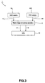
- FIG. 13 is a schematic functional block diagram of a plane detecting apparatus of the embodiment.
- FIG. 14 is a schematic illustration of the plane detecting process that employs the line segment extension method in the embodiment.
- FIG. 15 is a flow chart of the plane detecting process, using the line segment extension method
- FIGS. 16A through 16C are schematic illustrations of a staircase, in which FIG. 16A is a schematic frontal perspective view of the staircase; FIG. 16B is a schematic lateral perspective view of the staircase, and FIG. 16C is a schematic oblique perspective view of the staircase;
- FIGS. 17A through 17C are schematic illustrations of another staircase, in which FIG. 17A is a schematic frontal perspective view of the staircase; FIG. 17B is a schematic lateral perspective view of the staircase; and FIG. 17C is a schematic oblique perspective view of the staircase;
- FIG. 18A is an image of the schematic frontal perspective view of the staircase of FIG. 17A as taken by a stereovision system
- FIGS. 18B through 18D are schematic illustrations of the three-dimensional distance data acquired from the image of FIG. 18A ;
- FIG. 19A is an image of the schematic lateral perspective view of the staircase of FIG. 17B as taken by a stereovision system and FIGS. 19B through 19D are schematic illustrations of the three-dimensional distance data acquired from the image of FIG. 19A ;
- FIG. 20A is an image of the schematic oblique perspective view of the staircase of FIG. 17C as taken by a stereovision system and FIGS. 20B through 20D are schematic illustrations of the three-dimensional distance data acquired from the image of FIG. 20A ;
- FIG. 21 is a schematic illustration of a robot apparatus equipped with a means for applying a texture to an object
- FIG. 22 is a schematic illustration of an operation of updating a three-dimensional grid according to the outcome of an observation as viewed in the direction of the y-axis, showing a lateral view of the robot apparatus;
- FIG. 23 is a schematic illustration of a three-dimensional grid showing a region same as that of the real space of FIG. 11 ;
- FIG. 24 is a schematic illustration of a 2.5-D height map
- FIG. 25 is a flow chart of a process for verifying a 2.5-D height map by the height map verifying section
- FIG. 26 is a flow chart of a process for updating a height map by the height map updating section
- FIG. 27 is a schematic illustration of an environment map built by the environment map building section of FIG. 5 ;
- FIG. 28 is a schematic illustration of a state where a robot apparatus finds a box Z in the visual field of the robot apparatus and recognizes it;
- FIG. 29 is a schematic illustration of a state where the box Z of FIG. 28 is missing;
- FIG. 30 is a schematic illustration of an environment map built by the robot apparatus on the basis of the state of FIG. 28 ;
- FIG. 31 is a schematic illustration of an environment map built only from a 2.5-D height map
- FIG. 32 is a schematic illustration of an environment map built from a 2.5-D height map and complemented by a three-dimensional grid
- FIG. 33 is another schematic illustration of a state where a robot apparatus finds a box Z in the visual field of the robot apparatus and recognizes it;
- FIG. 34 is a schematic illustration of a state where a box Z that is not found in the state of FIG. 33 is moved into the visual field of the robot apparatus of FIG. 28 ;
- FIG. 35 is a schematic illustration of an environment map built by the robot apparatus from the state of FIG. 33 ;
- FIG. 36 is a schematic illustration of an environment map built only from a 2.5-D height map.
- FIG. 37 is a schematic illustration of an environment map built from a 2.5-D height map and complemented by a three-dimensional grid.
- FIG. 3 is a schematic block diagram of the embodiment of environment map building apparatus, showing the configuration thereof.
- the environment map building apparatus 1 comprises a pair of CCD cameras 10 R, 10 L and a stereo image processing apparatus 12 arranged downstream relative to the CCD cameras 10 R, 10 L, (R and L being suffixes indicating right and left respectively throughout this letter of specification).
- the right image 11 R and the left image 11 L picked up by the two CCD cameras are input to stereo image processing apparatus 12 , which stereo image processing apparatus 12 computationally determines disparity data (distance information) of the images 11 R, 11 L and then a color image (YUV: luminance Y, UV color difference) 13 and a parallax image (YDR: luminance Y, parallax D, reliability R) 14 alternately for the left and right CCD cameras in each frame.
- YUV luminance Y, UV color difference
- YDR luminance Y, parallax D, reliability R
- the color image 12 and the parallax image 13 are input to CPU (control section) 15 .
- the CPU 15 receives the color image 13 and the parallax image 14 from the stereo image processing apparatus 12 as inputs and builds an environment map by means of software having a configuration as will be described hereinafter.
- the environment map building apparatus 1 comprises a stereovision system 2 that operates as distance data metering means for acquiring three-dimensional distance data, a plane (segmentation) detector 3 for receiving stereo data D 1 from the stereovision system 2 and detecting one or more than one planes in the environment from the stereo data D 1 and an environment map building section 4 for updating the environment map, which will be described in greater detail hereinafter from the plane data D 2 output from the plane detector 3 and outputting an environment map data D 5 (for updating a grid map and a height map).
- a stereovision system 2 that operates as distance data metering means for acquiring three-dimensional distance data
- a plane (segmentation) detector 3 for receiving stereo data D 1 from the stereovision system 2 and detecting one or more than one planes in the environment from the stereo data D 1
- an environment map building section 4 for updating the environment map, which will be described in greater detail hereinafter from the plane data D 2 output from the plane detector 3 and outputting an environment map data D 5 (for updating a grid map and
- the environment map building section 4 by turn includes a three-dimensional grid updating section 41 for building a three-dimensional environment map (to be referred to as three-dimensional grid hereinafter) or updating it on the basis of the detected surrounding environment, a height map verifying section 42 for verifying the height map on the basis of the obstacle probability data D 3 transmitted from the three-dimensional grid updating section 41 and a height map updating section 43 for updating the height information of the height map on the basis of the outcome of the verification.
- a three-dimensional grid updating section 41 for building a three-dimensional environment map (to be referred to as three-dimensional grid hereinafter) or updating it on the basis of the detected surrounding environment
- a height map verifying section 42 for verifying the height map on the basis of the obstacle probability data D 3 transmitted from the three-dimensional grid updating section 41
- a height map updating section 43 for updating the height information of the height map on the basis of the outcome of the verification.
- the three-dimensional environment map (three-dimensional grid) built by the three-dimensional grid updating section 41 expresses the surrounding environment by dividing an image of the surrounding environment into grids having predetermined horizontal and vertical dimensions. More specifically, the three-dimensional grid updating section 41 expresses a three-dimensional environment map as a set of unit grids (to be referred to cells hereinafter), each cell corresponding to a box-shaped space that is horizontally four centimeters long and four centimeters wide to provide a horizontal resolution of four centimeters but one centimeter high to provide a vertical resolution of one centimeter.
- the three-dimensional grid updating section 41 assigns a probability with which each cell is occupied by an object and modifies the probability of occupation of each cell on the basis of observation data. A threshold value is provided for the probability of occupation and the state of the environment is expressed as a map according to whether the probability of occupation of each cell is greater than the threshold value or not.
- the three-dimensional grid updating section 41 updates the built three-dimensional grid on the basis of the stereo data D 1 and the plane data D 2 and outputs the updated three-dimensional grid to the height map verifying section 42 .
- the height map verifying section 42 builds a relative-to-base-plane height map that expresses the height from a two-dimensional base plane on the basis of the stereo data D 1 .
- the relative-to-base-plane height map is a map that expresses an environment by discriminating a detected plane by means of information showing the height from a two-dimensional base plane. It is referred to as 2.5-D height map for the purpose of the present invention because it does not contain information on planes parallel to the vertical direction (Z-axis) unlike a three-dimensional grid.
- a 2.5-D height map is made to correspond to the three-dimensional grid built by the three-dimensional grid updating section 41 by applying a coordinate system to make it a map for the region same as that of the three-dimensional grid so as to make it possible to identify any specific region in the 2.5-D height map.
- the height map verifying section 42 compares the height information on the cells of the three-dimensional grid and the height information of the cells of the 2.5-D height map and verifies the height map.
- the height map updating section 43 modifies the information on the relative-to-base-plane height map on the basis of the information on the three-dimensional map. In other words, whenever necessary, it executes a process of updating the height information of the 2.5-D height map on the basis of the plane data D 2 and the obstacle probability data D 3 of the three-dimensional grid.
- the environment map building apparatus 1 firstly observes the surrounding environment by means of the stereovision system 2 and outputs the stereo data D 1 that is the three-dimensional distance information computed on the basis of the parallax images of the stereo-viewing cameras. More specifically, it compares the images input from the left and right cameras that correspond to the two eyes of human being for each pixel and its vicinity and estimates the distance to an object from the parallax images. Then, it outputs three-dimensional distance information as image (distance information).
- the environment map building apparatus 1 can recognize a plurality of planes existing in the surrounding environment by detecting them by means of the plane detector 3 from the stereo data D 1 .
- the environment map building apparatus 1 builds an environment map that is divided into grids of predetermined horizontal and vertical dimensions for the surrounding environment acquired by the stereovision system 2 from the plane data D 2 by means of the environment map building section 4 .
- the environment map building apparatus 1 updates the environment map by means of the stereo data D 1 and the plane data D 2 and builds a 2.5-D height map by referring to the obstacle existing probabilities of the three-dimensional grid.
- This mobile type robot apparatus is a biped type utility robot apparatus that supports human activities in various different scenes of daily life in a domestic environment or some other environment and is adapted to behave according to the internal state (anger, grief, joy, pleasure, etc.) thereof. Moreover, it is an entertainment robot apparatus that can express basic actions of man. The robot apparatus can form its own moving route, utilizing the environment map built by the environment map building apparatus 1 .
- FIG. 6 is a schematic perspective view of this embodiment of robot apparatus according to the invention.
- the robot apparatus 201 of this embodiment comprises a trunk unit 202 , a head unit 203 linked to a predetermined position of the trunk unit 202 , left and right arm units 204 R/L and left and right leg units 205 R/L, the arm units 204 R/L and the leg units 204 R/L also being linked to the trunk unit 202 .
- FIG. 7 schematically illustrates the degree of freedom of each of the joints of the robot apparatus 201 .
- the neck joint that supports the head unit 203 has three degrees of freedom realized by a neck joint yaw axis 101 , a neck joint pitch axis 102 and a neck joint roll axis 103 .
- Each of the arm units 204 R/L, or the upper limb units has a shoulder joint pitch axis 107 , a shoulder joint roll axis 108 , an upper arm yaw axis 109 , a elbow joint pitch axis 110 , a forearm yaw axis 111 , a wrist joint pitch axis 112 , a wrist joint roll axis 113 and a hand section 114 .
- the hand section 114 is in fact a multi-joint multi-degree-of-freedom structure that includes a thumb and a plurality of fingers.
- each of the arm units 204 R/L has seven degrees of freedom.
- the trunk unit 202 has a trunk pitch axis 104 , a trunk roll axis 105 and a trunk yaw axis 106 and hens has three degrees of freedom
- Each of the leg units 205 R/L, or the lower limb units has a hip joint yaw axis 115 , a hip joint pitch axis 116 , a hip joint roll axis 117 , a knee joint pitch axis 118 , an ankle joint pitch axis 119 , an ankle joint roll axis 120 and a foot section 121 .
- the intersection of the hip joint pitch axis 116 and the hip joint roll axis 117 is defined as the hip joint position of the robot apparatus 201 .
- the foot section is in fact a multi-joint multi-degree-of-freedom structure that includes a sole. However, the foot section 121 is assumed to have zero degrees of freedom in this letter of specification. Therefore, each of the leg units 205 R/L has six degrees of freedom.
- entertainment robot apparatus are not necessarily limited to 32 degrees of freedom. It may be needless to say that the degrees of freedom and hence the number of joints can be increased or decreased appropriately depending on the restrictive conditions and the requirements of the specification to be met for designing and forming a robot.
- Each of the degrees of freedom of the robot apparatus 201 is realized by means of an actuator.
- each actuator is preferably compact and lightweight.
- the robot apparatus comprises a control system for controlling the overall motion of the robot apparatus that is typically arranged in the trunk unit 202 .
- FIG. 8 is a schematic block diagram of the control system of the robot apparatus of 201 .
- the control system comprises a thinking control module 200 that controls the emotional judgment and the sentimental expression of the robot apparatus that dynamically respond to the user-related input or the like and a movement control module 300 for controlling the concerted movement of the whole body of the robot apparatus 201 that is driven to move by actuators 350 .
- the thinking control module 200 includes a CPU (central processing unit) 211 that executes arithmetic processing operations relating to the emotional judgment and the sentimental expression, a RAM (random access memory) 212 , a ROM (read only memory) 213 and an external memory device (which may include a hard disc drive) 214 . It is a stand-alone type information processing device that can process various pieces of information in a self-conclusive manner in the module itself.
- the thinking control module 200 decides the current emotion and the current will of the robot apparatus 201 according to the external stimuli including the image data input from image input device 251 and sound data input from sound input device 252 .
- the robot apparatus 201 recognizes the expression of the user from the input image data and reflects the information to the sentiment and the will of the robot apparatus 201 so that the robot apparatus 201 can express its own action corresponding to the expression of the user.
- the image input device 251 typically comprises a plurality of CCD (charge coupled device) cameras, and can obtain distance information from the image picked up by these cameras.
- the sound input device 252 typically comprises a plurality of microphones.
- the thinking control module 200 issues a command for carrying out an action or behavior sequence according to the decision made by the robot apparatus 1 by moving the four limes, to the movement control module 300 .
- the movement control module 300 comprises a CPU 311 for controlling the concerted movement of the entire body of the robot apparatus 201 , a RAM 312 , a ROM 313 and an external memory device (which may include a hard disc drive) 314 .
- It is a stand-alone type information processing device that can process various pieces of information in a self-conclusive manner in the module itself.
- the external memory device 314 can accumulate walking patterns, ZMP trajectories and other behavior plans computationally determined on an offline basis.
- the movement control module 300 is connected to various devices of the robot apparatus 201 , shown in FIG. 6 , including the actuators 350 for realizing the degrees of freedom of the joints that are distributed in the whole body of the robot apparatus 201 as illustrated in FIG. 6 , a distance sensor (not shown) for metering the distance between the robot apparatus 201 and an object, an attitude sensor 351 for observing the attitude and the inclination of the trunk unit 202 , landing verification sensors 352 , 353 for detecting the takeoff and the touchdown of the left and right soles, load sensors arranged on the soles 121 and a power source control device 354 for managing the power source that may typically be a battery, by way of the bus interface (I/F) 310 .
- the attitude sensor 351 is typically formed by combining an acceleration sensor and a gyro sensor, whereas the landing verification sensors 352 , 353 are formed by using proximity sensors, micro-switches or the like.
- the thinking control module 200 and the movement control module 300 are built on a common platform and connected to each other by way of respective bus interfaces 210 , 310 .
- the movement control module 300 controls the concerted movement of the whole body of the robot apparatus 201 that is produced by the actuators 350 in order to express the action instructed by the thinking control module 200 to take. More specifically, the CPU 311 takes out an action that corresponds to the behavior specified by the thinking control module 200 from the external memory device 314 or internally generates an action pattern. Then, the CPU 311 defines the movement of each of the feet, the ZMP trajectory, the movement of the trunk, that of each of the upper limbs, the horizontal position and the height of the waist and so on according to the specified action pattern and transfers the command values for realizing the action as indicated by the definitions to the respective actuators 350 .
- the CPU 311 can adaptively control the concerted movement of the whole body of the robot apparatus 201 by detecting the attitude and the inclination of the trunk unit 202 of the robot apparatus 201 according to the output signal of the attitude sensor 351 and, at the same time, if each of the leg units 205 R/L is in an idle state or in a standing state according to the output signal of the corresponding landing verification sensor 352 or 353 . Still additionally, the CPU 311 controls the attitude and the movement of the robot apparatus 201 so as to make the ZMP position to be constantly directed toward the center of the ZMP stability region.
- the movement control module 300 is adapted to feedback the extent to which the behavior of the robot apparatus is manifested according to the will decided by the thinking control module 200 and hence the status of the processing operation of itself to the thinking control module 200 . In this way, the robot apparatus 201 can judge the situation of itself and its surroundings and behave autonomously according to the control program it stores.
- FIG. 9 is a schematic block diagram of the system for recognizing the surrounding environment of a robot apparatus as an environment map when the environment map building apparatus 1 of FIG. 3 is applied to the robot apparatus.
- the robot apparatus 201 comprises actuators 16 and various sensors 17 in addition to the components illustrated in FIG. 3 .
- an image input apparatus 251 is used for the pair of CCD cameras 10 R, 10 L and the thinking control module 200 operates as stereo image processing apparatus 12 .
- the stereo image processing apparatus 12 computationally determines the parallax information (distance information) of the images 11 R, 11 L and then calculates a color image 13 and a parallax image 14 alternately for the left and right CCD cameras in each frame.
- the color image 12 and the parallax image 13 are input to the CPU (control section) 15 contained in the trunk unit 202 of the robot apparatus 1 .
- Actuators 16 are arranged at each joint of the robot apparatus 1 and a control signal 18 that represents a command from the CPU 15 is supplied to each of the actuators to drive the motor of the actuator according to the command value of the control signal 18 .
- Each joint (actuator) is equipped with a potentiometer and the rotary angle of the motor is transmitted to the CPU at each necessary time.
- the various sensors 17 including the potentiometers fitted to the respective actuators, the touch sensors fitted to the soles and the gyro sensor fitted to the trunk unit acquire information on the current state of the robot apparatus that may include the current angle of each joint, grounding information, attitude information and the like and output the acquired information to the CPU 15 as sensor data 19 .
- the CPU 15 receives the color image 13 and the parallax image 14 coming from the stereo image processing apparatus 12 and the sensor data 19 on all the angles of the joints, or the actuators, as input and executes an environment-responding expression process by means of software.
- the software of the robot apparatus 201 is designed on an object unit basis so as to execute various recognition processes for recognizing the current position, the quantity of movement, the obstacles in the surrounding environment and the environment map and output a string of actions to be ultimately taken by the robot apparatus.
- the robot apparatus uses two coordinate systems including a camera coordinate system in world coordinate system (to be also referred to as absolute coordinate system hereinafter) which is a coordinate system having its origin at a specific object such as a landmark, which will be described hereinafter, and a robot-centered coordinate system (to be also referred to as relative coordinate system) having its origin in the robot apparatus itself.
- FIG. 10 is a schematic functional block diagram of the system of the embodiment of robot apparatus 201 of FIG. 6 for executing a process down to expressing the environment as an environment map on the basis of the stereo data acquired by the image input apparatus 251 and determining the moving route on the basis of the environment map.
- the robot apparatus 201 comprises a kinematic odometry 5 for receiving the stereo data D 1 including parallax information and a parallax image and the sensor data D 6 as input, determining the joint angles from the sensor data 6 at the time when the stereo data D 1 is picked up and transmitting joint angle data D 7 , a robot attitude (pose) updating section 6 for converting the robot-centered coordinate system into the camera coordinate system on the basis of the joint angle data D 7 from the kinematic odometry 5 and transmitting robot attitude data D 8 and a route determining section (path planner) 7 for controlling action commands for determining the moving route or the like of the robot apparatus 201 on the basis of the environment map data D 5 from the environment map building section 4 and the robot attitude data from the robot attitude updating section 7 in addition to the stereovision system 2 , the plane detector 3 and the environment map building section 4 .
- a kinematic odometry 5 for receiving the stereo data D 1 including parallax information and a parallax image and
- the robot apparatus 201 firstly observes the surrounding environment by means of the stereovision system 2 and outputs stereo data D 1 as three-dimensional distance information that is computationally obtained on the basis of the parallax between the two eyes. More specifically, it compares the images input from the left and right cameras that correspond to the two eyes of human being for each pixel and its vicinity and estimates the distance to an object from the parallax images. Then, it outputs three-dimensional distance information as image (distance information). The robot apparatus 201 can recognize a plurality of planes existing in the surrounding environment by detecting them by means of the plane detector 3 from the distance image. Additionally, the environment map building section 4 builds an environment map of the surroundings of the robot apparatus.
- the route determining section 7 realizes the moving action of the robot apparatus in the environment by means of the environment map data D 5 and the robot attitude data D 8 .
- the robot apparatus 201 can recognize the intra-visual-field information on the staircase, the obstacles and the steps found in its own visual field as environment map by applying the environment map building apparatus 1 to the robot apparatus 201 and grasp the surrounding environment including the obstacles, the staircase and steps by referring to the environment map. Then, as a result of the recognition, the robot apparatus can take actions that may typically include an action of stepping up a staircase, a walking action and an action of searching a moving route by using the environment map.
- FIG. 11 is a schematic illustration of a real space recognized by the robot apparatus 201 that is equipped with the environment map building apparatus 1 .
- the real space S 500 of FIG. 11 contains a staircase ST 503 including planes PL 501 and PL 502 that the robot apparatus 201 can step up and obstacles OB 504 and OB 505 that are not surmountable to the robot apparatus.
- FIG. 12 is a schematic illustration of an operation of imaging the surrounding environment of the robot apparatus 201 .
- the floor surface (base plane) is referred to as x-y plane while the height direction is referred to as z-axis as shown in FIG. 12 .
- the visual field of the robot apparatus 201 having an image input section (stereo cameras) in the head unit 203 is confined to a predetermined range located in front of the robot apparatus 201 as shown in FIG. 12 .
- the robot apparatus 201 recognizes the environment in the visual field and builds an environment map for it.
- the stereovision system 2 acquires three-dimensional distance data and image data such as color image data and parallax images that are obtained by means of the stereo cameras and transmits the acquired distance information (stereo data D 1 ) to the plane detector 3 .
- the plane detector 3 detects a plurality of planes existing in the environment from the distance information (stereo data D 1 ) output from the distance meter of the stereovision system and outputs plane data D 2 .
- the technique for detecting planes may be selected from known plane detecting techniques such as the line segment extension method and the Hough transformation method. To detect a plurality of planes like a staircase from the distance data including noises, the line segment extension method may typically be used to accurately detect planes.
- the plane detector 3 includes a line segment extracting section 31 for selecting groups of distance data points, the distance data points of each group being estimated to be on the same plane, out of the distance data points of an image and extracting a line segment for each group of distance data points and a region extending section 32 for extracting one or more than one plane regions existing in the image from the groups of all the line segments extracted by the line segment extracting section 31 .
- the region extending section 32 arbitrarily selects three line segments that are estimated to be on the same plane from the groups of line segments and determines a base plane from them.
- the line segment extracting section 31 extracts a group of distance data points that are estimated to be on the same plane in a three-dimensional space out of the data string of each column or each row in the distance image and generates one or more than one line segments from the group of distance data points depending on the distribution of the distance data points of the group. In other words, if it is judged that the distribution is uneven, it is determined that the distance data points of the group are not found on the same plane and the distance data points are divided into groups. Then, the operation of judging if the distribution of the distance data points of each of the groups produced by the division is even or uneven is repeated. A line segment is generated from each group of the distance data points whose distribution is judged to be uniform. The above operation is repeated for all the data strings and the generated group of line segments D 21 is output to the region extending section 32 .
- the region extending section 32 selects three line segments that are estimated to be on the same plane out of the group of line segments D 21 and determines a plane that can be a seed of a base plane from the planes that are defined by three line segments. Then, the region extending section 32 divides the distance image into a plurality of planes by means of the technique of extending a region by sequentially uniting the lines belonging to the plane identical with the region of the plane that can be a seed of a base plane (seed region) and outputs the plane data D 2 on the groups of the planes.
- the plane detecting section 3 is adapted to detect planes by the line segment extension method because this method is adapted to detect planes from an acquired image if it contains a plurality of planes such as those of a staircase unlike the Hough transformation method that is adapted to detect a dominant plane contained in an acquired image.
- line segments are generated depending on the distribution of distance data points to make it possible to acquire robust results of plane detection relative to measurement noises.
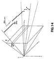
- FIG. 14 is a schematic illustration of a plane detecting process using the line segment extension method.
- the data string in the row direction or in the column direction is processed for image 20 picked up from focal point F.
- line segments are generated from the distance data points that are estimated to be belonging to the same plane by utilizing the fact that a straight line is formed when a group of distance data points belongs to the same plane in a pixel string in the row direction of an image (image row), for example.
- a plane is estimated and detected on the basis of a group of line segments that form the same plane out of the obtained groups of line segments.
- FIG. 15 is a flow chart of the plane detecting process, using the line segment extension method.
- a distance image is input (Step S 1 ) and line segments are determined from the data points that are estimated to be belonging to the same plane in each pixel string in the row direction (or the column direction) of the distance image (Step S 2 ).
- the line segments that are estimated to be belonging to the same plane are extracted from the group of line segments and the plane that is formed by the line segments is determined (Step S 3 ).
- Step S 3 firstly regions that can be a seed of a plane (to be referred to as seed region hereinafter) are selected and then the most likely seed region is selected.
- three line segments including a line extending in the row direction out of vertically adjacent lines (or in the column direction out of horizontally adjacent lines) are required to be in the same plane. Then, the plane to which the seed region formed by the selected three line segments belongs is used as base plane and the plane that is determined from the three line segments by averaging is determined in advance.
- the region defined by the three line segment is referred to as base plane region.
- the straight line formed by the pixel string in the row direction (or the column direction) adjacent to the selected seed region belongs to the base plane or not by comparing a spatial distance. If the straight line belongs to the base plane, it is added to the base plane region (region extending process) and the base plane is updated so as to include the added line segment (plane updating process). The above processes are repeated until there is no longer any line segment existing on the same plane among the data strings adjacent to the plane region. Then, the above operation of detecting seed regions and executing the plane updating process and the region extending process is repeated until there is no longer any region (of three line segments) that can be a seed. Finally, the regions that form the same plane are selected from the obtained plurality of regions and linked together.
- Step S 4 is additionally provided for a plane re-determining process where the line segment or line segments that deviate from the obtained plane by more than a predetermined threshold value are excluded from the group of line segments that are assumed to be belonging to the obtained plane to determine a final plane, which will be described hereinafter.
- the process of detecting line segments from the three-dimensional distance data and each region where the line segments are grouped for the same plane is same as the known plane detecting process using the line segment extension method.
- this embodiment differs from conventional method in terms of the line segment extracting method that is employed in Step S 2 .
- a problem such as over segmentation or under segmentation can arise if line segments are generated from groups of distance data points to make them fit the latter unless the threshold value is modified depending on the accuracy, or the level of refinement, of the distance data points.
- a technique of analyzing the distribution of distance data and adaptively modifying the threshold value depending on the accuracy of distance data and noises is introduced into this embodiment for the operation of extracting line segments.
- FIGS. 16A through 17C the planes detected by the above-described plane detecting process will be described by referring to FIGS. 16A through 17C .
- the planes detected by the plane detector 3 are those of staircases ST 1 and ST 2 as shown in FIGS. 16A through 17C .
- FIG. 16A and 17A are schematic frontal perspective views of the respective staircases.
- FIG. 16B and FIG. 17B are schematic lateral perspective views of the respective staircases.
- FIG. 16C and FIG. 17C are schematic oblique perspective views of the respective staircases.
- each surface of a staircase that people and robot apparatus use for going up or down along the staircase (a surface where a foot or a movable leg section is placed) is referred to as tread and the height from a tread to the next tread (the height of a step) is referred to as riser.
- the steps of a staircase are denoted as the first step, the second step and so on from the lowest step.
- the staircase ST 1 illustrated in FIGS. 16A through 16C has three steps and the riser is 4 cm high, while the tread of the first step and that of the second step are 30 cm wide and 10 cm long and the tread of the third step, or the uppermost step, is 30 cm wide and 21 cm long.
- the staircase ST 2 illustrated in FIGS. 17A through 17C has three steps and the riser is 3 cm high, while the tread of the first step and that of the second step are 33 cm wide and 12 cm long and the tread of the third step, or the uppermost step, is 33 cm wide and 32 cm long.
- FIGS. 18A , 19 A and 20 A are respectively an image of the schematic frontal perspective view, that of the schematic lateral view and that of the oblique perspective view of the staircase ST 2 of FIGS. 17A through 17C as taken by a stereovision system.
- FIGS. 18B , 18 C, 19 B, 19 C, 20 B and 20 C are schematic illustrations of the three-dimensional distance data acquired from the image of FIGS. 18A , 19 A and 20 A.
- the three-dimensional distance data as illustrated in FIGS. 18B and 18C are obtained when the staircase ST 2 is shot from the front side thereof shown in FIG. 18A .
- the horizontal axis represents the y-direction and the vertical axis represents the x-direction.
- the grounding surface of the robot apparatus 201 is 0 and the height of the staircase is expressed by gradation, the higher the paler in the direction of the z-axis (height direction).
- gradation the higher the paler in the direction of the z-axis (height direction).
- the data points of the region corresponding to the tread of the second step are paler than those of the region corresponding to the tread of the first step and the data points of the region corresponding to the third step are paler than those of the region corresponding to the tread of the second step.
- the substantially trapezoidal region where distance data are shown represents the range that the robot apparatus can shoot by its stereovision system (view field range).
- the distance data points are substantially divided into four categories, the darkest area corresponding to the region with the smallest value in the z-direction representing the floor surface.
- the horizontal axis represents the y-direction and the vertical axis represents the z-direction, while the distance in the x-direction is expressed by gradation.
- the horizontal axis represents the x-direction and the vertical axis represents the z-direction, while distance in the y-direction is expressed by gradation.
- the three-dimensional distance data as illustrated in FIGS. 19B and 19C are obtained when the staircase ST 2 is shot by the stereovision system of the robot apparatus 201 from a lateral side thereof shown in FIG. 19A .
- the data points found in the uppermost region having a large value of the x-axis shows a level of gradation similar to the one in the region where the height is 0 to indicate that the floor behind staircase ST 2 is observed.
- the three-dimensional distance data as illustrated in FIGS. 19B and 19C are obtained when the staircase ST 2 is shot by the stereovision system of the robot apparatus 201 from an oblique direction in FIG. 20A . It will be seen that the four regions including the floor surface and the treads of the first through third steps are expressed by gradation so as to be discriminated clearly.
- the surface of the staircase ST 2 is required to bear a pattern (texture) in order for the robot apparatus to acquire such three-dimensional distance data by means of stereo cameras.
- any object bearing no pattern cannot be recognized by computations and the robot apparatus cannot accurately meter the distance between the object and the robot apparatus because it is not possible to recognize the object by means of the parallax between the two images picked up by two cameras.
- the accuracy of measurement in acquiring distance data by means of a stereovision system depends on the texture of the object of observation.
- the term “parallax” as used herein refers to the difference between the image of a spot in space mapped by the left eye (camera) and the image mapped by the right eye (camera). Thus, the parallax varies as a function of the distance from each of the cameras.
- the robot apparatus is typically provided in the head unit with a light source 21 for outputting infrared rays as a projection means.
- the light source 21 projects (irradiates) infrared rays onto staircase ST 3 and other objects have no or little texture such as walls and operates as a pattern applying means for applying a random pattern PT to the object.
- the pattern applying means for applying a random pattern PT is not limited to a light source for projecting infrared rays so long as it can form a random pattern PT and acquire a distance image.
- the robot apparatus itself may alternatively draw a pattern on the object, although infrared rays provide an advantage that a pattern of infrared rays can be observed by the CCD cameras mounted in the robot apparatus, while it is not visible to human eyes.
- the three-dimensional grid updating section 41 of the environment map building section 4 receives the stereo data D 1 that is the three-dimensional information acquired by the stereovision system 2 and the plane data D 2 that is the outcome of the detection of the plane by means of the plane detector 3 relative to the three-dimensional information and builds a three-dimensional grid. Additionally, it executes the following process for all the unit grids (to be referred to as cells hereinafter) p (x, y, z) in the real space S 500 that is expressed by a three-dimensional grid.
- FIG. 22 is a schematic illustration of an operation of updating a three-dimensional grid according to the outcome of an observation as viewed in the direction of the y-axis, showing a lateral view of the robot apparatus.
- the shaded cells that are not found in the visual field (field of view) of the robot apparatus 201 are cells that are not measured yet, whereas the black cells are cells measured by the robot apparatus 201 and the white cells are cells located between the robot apparatus 201 and the points of measurement.
- the hatched region is an unconfirmed region.
- an empty process is executed on the cells located between cell p, which is the object point of measurement, and the stereo cameras 11 L, 11 R of the robot apparatus. Subsequently, an occupied process is executed on the cell that corresponds to the point of measurement p.
- the three-dimensional grid holds an obstacle existence probability (probability of being occupied by an obstacle) p(c) relative to the cells C.
- the empty process and the occupied process are statistic processes that are executed on these cells.
- the empty process is a process of reducing the obstacle existence probability
- the occupied process is a process of raising the obstacle existence probability.
- the Bayes' updating rule is adopted for the technique of computing the existence probability for the empty process and the occupied process.
- Formulas (1) and (2) shown below are used respectively to reduce the existence probability by the empty process and to raise the existence probability by the occupied process.
- the formula (1) expresses the probability of being “occupied” for a cell C having an obstacle existence probability of p(c).
- . . . ) are respectively a predetermined threshold value th for the probability by which the cell C is occupied and a predetermined threshold value th for the probability by which the cell C is not occupied respectively.
- FIG. 23 is a schematic illustration of a three-dimensional grid to each of whose cells an obstacle existence probability is given.
- the three-dimensional grid is formed by cells, each having a horizontal resolution of four centimeters and a vertical resolution of one centimeter. For the purpose of convenience, it shows a region same as that of the real space S 500 of FIG. 11 .
- the robot apparatus 201 acquires information on the surrounding environment at predetermined regular time intervals such as thirty times per second so that, when the robot apparatus 201 is moving, the real space S 500 that is expressed by the three-dimensional grid changes incessantly. Of the acquired cells, each of those that are viewed is expressed by 1, whereas each of those that are not viewed is expressed by 0.5.
- the occupancy probability will be gradually updated as the operation of acquiring information on the surrounding environment is conducted thirty times per second.
- the height map verifying section 42 of the environment map building apparatus 1 builds a 2.5-D height map formed by applying height information to the cells of the 2.5-D height map as analog information and verifies the 2.5-D height map, using the occupancy probability data (obstacle existence probability data) of each of the cells obtained from the three-dimensional grid.
- the conventional technique of recognizing the environment by a 2.5-D height map gives rise to a problem that the obstacle occupancy probability is not updated when the plane that was observed last time has disappeared or when an obstacle has moved into the visual field from the outside of the visual field.
- this embodiment dissolves the problem as the height map verifying section 42 verifies the 2.5-D height map by means of a three-dimensional grid.
- a three-dimensional grid is built and updated on the basis of an algorithm that no obstacle exist on the straight line that geometrically connects a point of measurement and the center of observation (the middle point of the stereo cameras).
- the height map verifying section 42 executes a process of updating the occupancy probability when the height information of the 2.5-D height map is made to correspond to the cells of the three-dimensional grid by referring to the occupancy probability of each cell of the three-dimensional grid.
- FIG. 24 is a schematic illustration of a 2.5-D height map.
- a 2.5-D height map holds height information h and an invalid flag for each cell of the corresponding two-dimensional grid that is expressed by rectangular grids.
- an invalid flag (inv) is given to it.
- a 2.5-D height map is expressed by means of a two-dimensional grid of 4 meters square comprising cells having a horizontal resolution of 4 centimeters. No vertical resolution is considered for a 2.5-D height map and height information is assigned to each cell.
- An invalid flag corresponds to an obstacle for a robot apparatus 201 .
- an unrealistic value for expressing a space such as ⁇ 10,000 may be given instead of an invalid flag so as to show an obstacle to the robot apparatus 201 .
- FIG. 25 is a flow chart of a process for verifying a 2.5-D height map by the height map verifying section 42 .
- the height map verifying section 42 acquires height information from the 2.5-D height map that is a height map relative to the base plane and makes it correspond to the height coordinates of the corresponding three-dimensional grid. Then, it compares the occupancy probability of each cell of the corresponding three-dimensional grid with the threshold value for determining if the cell represents an obstacle to be recognized or not. It judges that the cell does not represent an obstacle when the occupancy probability is smaller than the threshold value, whereas it judges that the cell represents an obstacle when the occupancy probability is greater than the threshold value so as to update the height information of the height map relative to the base plane.
- the height map verifying section 42 acquires the height of the grid for all the cells (i, j) in the 2.5-D height map, referring to the 2.5-D height map (Step S 11 ). If the height information h shows an invalid flag, it terminates the process (Step S 12 ; yes).
- the height information h determines index k for the three-dimensional grid by making the height information h properly correspond to the three-dimensional grid (Step S 13 ). Subsequently, it compares the obstacle existence probability p (Cijk) of each of the cells (i, j, k) in the three-dimensional grid that corresponds to the 2.5-D height map with a threshold value th for determining if the cell represents an obstacle to be recognized or not (Step S 14 ).
- the height map verifying section 42 judges that the cell does not represent an obstacle when the obstacle existence probability is smaller than the threshold value (Step S 14 ; no). At this time, the downstream height map updating section 43 updates the cells (i, j) of the 2.5-D height map on the basis of the algorithm for building a three-dimensional grid. To the contrary, the height map verifying section 42 judges that the cell represents an obstacle when the obstacle existence probability is greater than the threshold value (Step S 14 ; yes) and terminates the process. In other words, it does not update the height information h of the 2.5-D height map.
- the volume of computations can be reduced by applying the above-described process only to the cell region that corresponds to the visual field in the grid.
- the cell region that corresponds to the visual field is denoted as bounding box.
- the height map updating section 43 updates the 2.5-D height map on the basis of the plane data D 2 obtained by the plane detector 3 and the obstacle probability data D 3 of the three-dimensional grid.
- the height map updating section 43 updates the 2.5-D height map when the plane to which the point of measurement p belongs is a horizontal plane and the obstacle existence probability of the cell of the three-dimensional grid that corresponds to the point of measurement p is greater the threshold value th for all the points of measurement (cells) p included in the space to be measured in the visual field of the robot apparatus 201 .
- FIG. 26 is a flow chart of a process for updating a 2.5-D height map by the height map updating section 43 .
- the height map updating section 43 acquires plane information on the planes to which all the point of measurement (cells) p located in the visual field belong (Step S 21 ).
- the plane information is the plane data D 2 that is the outcome of the plane detecting operation of the plane detector 3 . More specifically, it acquires the plane ID (p_id) showing the plane to which a point of measurement p belongs and if the p_id is valid (Step S 22 ; yes), it retrieves plane information on the plane to which the point of measurement p belongs out of the detected group of planes, using the p_id as key (Step S 23 ).
- the height map updating section 43 checks if the plane to which the point of measurement p belongs is a horizontal plane or not and, if the plane is not a horizontal plane (Step S 24 ; no), it terminates the process. If, on the other hand, the plane is a horizontal plane (Step S 24 ; yes), it refers to the obstacle existence probability of the cell in the three-dimensional grid that corresponds to the point of measurement p (Step S 25 ). More specifically, it determines the index (i, j, k) of the cell as positional information of the three-dimensional grid from the positional information (x, y, z) of the point of measurement p in the 2.5-D height map and refers to the cell of the three-dimensional grid according to the index.
- the height map updating section 43 determines if the height information h for the point of measurement p has to be updated or not (Step S 26 ). If the occupancy probability of the cell of the three-dimensional grid that corresponds to the point of measurement p is greater than the threshold value th and indicates the existence of an obstacle (Step S 26 ; yes), it updates the corresponding cell (i, j) of 2.5-D height map with the height information h (Step S 27 ).
- FIG. 27 is a schematic illustration of an environment map built by way of the above-described sequence of processes. As pointed out above, it is possible to dissolve the problem described earlier by referring to FIGS. 1 and 2 by complementing the 2.5D-height map by the corresponding three-dimensional grid. In the environment map, height information h or the probability of existing an obstacle (obs) or not is applied to each cell in the two-dimensional grid.
- the expression of the environment only by the 2.5-D height map and the expression of the same environment by the 2.5-D height map complemented by the corresponding three-dimensional grid built by the robot apparatus 201 by means of the above described environment map building method will be compared for the case where a plane once recognized by the robot apparatus 201 has disappeared and for the case where a plane once recognized by the robot apparatus 201 has been moved.
- FIG. 28 is a schematic illustration of a state where the robot apparatus 201 finds a box Z in its visual field and recognizes it.
- FIG. 29 is a schematic illustration of a state where the box Z of FIG. 28 is missing.
- FIG. 30 is a schematic illustration of an environment map built by the robot apparatus 201 on the basis of the state of FIG. 28 . The cells are discriminated by shading to indicate that they have different pieces of height information h.
- FIG. 30 shows that the robot apparatus 201 detects a plane that corresponds to the box Z placed in front of it.
- FIG. 31 is a schematic illustration of an environment map built only from the 2.5-D height map.
- FIG. 32 is a schematic illustration of an environment map built from the 2.5-D height map and complemented by the three-dimensional grid.
- the cells of the region that the robot apparatus 201 recognized when the box Z was there but can no longer see it have not been updated due to the problem pointed out earlier by referring to FIGS. 1 and 2 although the box Z has been removed and hence the plane of the box Z is no longer there.
- part of the box Z is erroneously recognized as a plane.
- the residual cells are properly updated as a result of a verification process using the algorithm for building the three-dimensional grid.
- FIGS. 33 and 34 show how the robot apparatus 201 recognizes the box Z in its visual field.
- FIG. 34 is a schematic illustration of a state where a box Z that is not found in the state of FIG. 33 is moved into the visual field of the robot apparatus 201 .
- FIG. 35 is a schematic illustration of an environment map built by the robot apparatus 201 from the state of FIG. 33 . The cells are discriminated by shading to indicate that they have different pieces of height information h.
- FIG. 36 is a schematic illustration of an environment map built only from the 2.5-D height map.
- FIG. 37 is a schematic illustration of an environment map built from the 2.5-D height map and complemented by the corresponding three-dimensional grid.
- the cells that are hidden by the top surface of the box Z that has been moved in and become invisible from the robot apparatus 201 are erroneously recognized as the original plane.
- the residual cells are properly updated as a result of a verification process using the algorithm for building the three-dimensional grid.
- the robot apparatus 201 can determine its moving route by means of the route determining section (path planner) 7 on the basis of the environment map built by means of the above described environment map building method.
- the technique of confirming the movable region by actually moving in the environment (space S 500 ) recognized on the basis of the environment map may be used along with the technique of searching for the moving route by means of the conventional two-dimensional grid.
- the environment map building method As described above, with the environment map building method according to the embodiment of the invention, only the detected planes are expressed in the 2.5-D height map and all the other cells are expressed as obstacles. Height information h is applied to the cells. The levels that the robot apparatus 201 cannot step up as indicated by the height information h may be expressed as obstacles or staircases.
- the environment map building method it is possible to build an environment map that is highly robust against observation noises by complementing a 2.5-D plane map that is weak relative to observation noises by a three-dimensional grid adapted to statistically process the obstacle existence probability of each cell. While a three-dimensional grid may reduce the processing speed when the detection accuracy has to be raised because the vertical resolution relies on the cell size, the environment map building method according to the embodiment of the invention makes it possible to accurately express heights with a relatively small amount of data because the height information h can be held as analog values for the 2.5-D height map by using a three-dimensional grid built with a relatively coarse resolution to suppress the quantity of computations.
- the environment map building method according to the invention dissolves the problem of the weakness relative to observation noises while it fully exploits a 2.5-D height map that is advantageous when fine resolutions are required in the height direction to detect planes and staircases that a robot apparatus can step up.
Landscapes
- Engineering & Computer Science (AREA)
- Physics & Mathematics (AREA)
- General Physics & Mathematics (AREA)
- Theoretical Computer Science (AREA)
- Computer Vision & Pattern Recognition (AREA)
- Multimedia (AREA)
- Manipulator (AREA)
- Processing Or Creating Images (AREA)
- Image Processing (AREA)
- Image Analysis (AREA)
Abstract
Description
Claims (13)
Applications Claiming Priority (2)
| Application Number | Priority Date | Filing Date | Title |
|---|---|---|---|
| JPP2004-188868 | 2004-06-25 | ||
| JP2004188868A JP4479372B2 (en) | 2004-06-25 | 2004-06-25 | Environmental map creation method, environmental map creation device, and mobile robot device |
Publications (2)
| Publication Number | Publication Date |
|---|---|
| US20060025888A1 US20060025888A1 (en) | 2006-02-02 |
| US7912583B2 true US7912583B2 (en) | 2011-03-22 |
Family
ID=35733420
Family Applications (1)
| Application Number | Title | Priority Date | Filing Date |
|---|---|---|---|
| US11/165,047 Active 2028-05-28 US7912583B2 (en) | 2004-06-25 | 2005-06-24 | Environment map building method, environment map building apparatus and mobile robot apparatus |
Country Status (2)
| Country | Link |
|---|---|
| US (1) | US7912583B2 (en) |
| JP (1) | JP4479372B2 (en) |
Cited By (55)
| Publication number | Priority date | Publication date | Assignee | Title |
|---|---|---|---|---|
| US20090125175A1 (en) * | 2007-11-09 | 2009-05-14 | Samsung Electronics Co., Ltd. | Apparatus and method for generating three-dimensional map using structured light |
| US20090316956A1 (en) * | 2008-06-23 | 2009-12-24 | Hitachi, Ltd. | Image Processing Apparatus |
| US20100040279A1 (en) * | 2008-08-12 | 2010-02-18 | Samsung Electronics Co., Ltd | Method and apparatus to build 3-dimensional grid map and method and apparatus to control automatic traveling apparatus using the same |
| US20100067738A1 (en) * | 2008-09-16 | 2010-03-18 | Robert Bosch Gmbh | Image analysis using a pre-calibrated pattern of radiation |
| US20100094460A1 (en) * | 2008-10-09 | 2010-04-15 | Samsung Electronics Co., Ltd. | Method and apparatus for simultaneous localization and mapping of robot |
| US20100114374A1 (en) * | 2008-11-03 | 2010-05-06 | Samsung Electronics Co., Ltd. | Apparatus and method for extracting feature information of object and apparatus and method for creating feature map |
| US20110224840A1 (en) * | 2010-03-12 | 2011-09-15 | U.S.A As Represented By The Administrator Of The National Aeronautics And Space Administration | Methods of Real Time Image Enhancement of Flash LIDAR Data and Navigating a Vehicle Using Flash LIDAR Data |
| US20110245973A1 (en) * | 2003-12-09 | 2011-10-06 | Yulun Wang | Protocol for a remotely controlled videoconferencing robot |
| US8836751B2 (en) | 2011-11-08 | 2014-09-16 | Intouch Technologies, Inc. | Tele-presence system with a user interface that displays different communication links |
| US8849679B2 (en) | 2006-06-15 | 2014-09-30 | Intouch Technologies, Inc. | Remote controlled robot system that provides medical images |
| US8849680B2 (en) | 2009-01-29 | 2014-09-30 | Intouch Technologies, Inc. | Documentation through a remote presence robot |
| US8897920B2 (en) | 2009-04-17 | 2014-11-25 | Intouch Technologies, Inc. | Tele-presence robot system with software modularity, projector and laser pointer |
| US8902278B2 (en) | 2012-04-11 | 2014-12-02 | Intouch Technologies, Inc. | Systems and methods for visualizing and managing telepresence devices in healthcare networks |
| US8965579B2 (en) | 2011-01-28 | 2015-02-24 | Intouch Technologies | Interfacing with a mobile telepresence robot |
| US8983174B2 (en) | 2004-07-13 | 2015-03-17 | Intouch Technologies, Inc. | Mobile robot with a head-based movement mapping scheme |
| US8996165B2 (en) | 2008-10-21 | 2015-03-31 | Intouch Technologies, Inc. | Telepresence robot with a camera boom |
| US9089972B2 (en) | 2010-03-04 | 2015-07-28 | Intouch Technologies, Inc. | Remote presence system including a cart that supports a robot face and an overhead camera |
| US9098611B2 (en) | 2012-11-26 | 2015-08-04 | Intouch Technologies, Inc. | Enhanced video interaction for a user interface of a telepresence network |
| US9138891B2 (en) | 2008-11-25 | 2015-09-22 | Intouch Technologies, Inc. | Server connectivity control for tele-presence robot |
| US9160783B2 (en) | 2007-05-09 | 2015-10-13 | Intouch Technologies, Inc. | Robot system that operates through a network firewall |
| US9174342B2 (en) | 2012-05-22 | 2015-11-03 | Intouch Technologies, Inc. | Social behavior rules for a medical telepresence robot |
| US9193065B2 (en) | 2008-07-10 | 2015-11-24 | Intouch Technologies, Inc. | Docking system for a tele-presence robot |
| US9198728B2 (en) | 2005-09-30 | 2015-12-01 | Intouch Technologies, Inc. | Multi-camera mobile teleconferencing platform |
| US9251313B2 (en) | 2012-04-11 | 2016-02-02 | Intouch Technologies, Inc. | Systems and methods for visualizing and managing telepresence devices in healthcare networks |
| US9264664B2 (en) | 2010-12-03 | 2016-02-16 | Intouch Technologies, Inc. | Systems and methods for dynamic bandwidth allocation |
| US9323250B2 (en) | 2011-01-28 | 2016-04-26 | Intouch Technologies, Inc. | Time-dependent navigation of telepresence robots |
| US9361021B2 (en) | 2012-05-22 | 2016-06-07 | Irobot Corporation | Graphical user interfaces including touchpad driving interfaces for telemedicine devices |
| US9381654B2 (en) | 2008-11-25 | 2016-07-05 | Intouch Technologies, Inc. | Server connectivity control for tele-presence robot |
| US9429934B2 (en) | 2008-09-18 | 2016-08-30 | Intouch Technologies, Inc. | Mobile videoconferencing robot system with network adaptive driving |
| US9602765B2 (en) | 2009-08-26 | 2017-03-21 | Intouch Technologies, Inc. | Portable remote presence robot |
| US9616576B2 (en) | 2008-04-17 | 2017-04-11 | Intouch Technologies, Inc. | Mobile tele-presence system with a microphone system |
| US9842192B2 (en) | 2008-07-11 | 2017-12-12 | Intouch Technologies, Inc. | Tele-presence robot system with multi-cast features |
| US9849593B2 (en) | 2002-07-25 | 2017-12-26 | Intouch Technologies, Inc. | Medical tele-robotic system with a master remote station with an arbitrator |
| US9888215B2 (en) | 2013-04-26 | 2018-02-06 | University Of Washington | Indoor scene capture system |
| US9974612B2 (en) | 2011-05-19 | 2018-05-22 | Intouch Technologies, Inc. | Enhanced diagnostics for a telepresence robot |
| US20180189599A1 (en) * | 2017-01-05 | 2018-07-05 | Kabushiki Kaisha Toshiba | Information processing apparatus, information processing method, and computer program product |
| US10093021B2 (en) * | 2015-12-02 | 2018-10-09 | Qualcomm Incorporated | Simultaneous mapping and planning by a robot |
| US10196104B1 (en) | 2016-05-04 | 2019-02-05 | Schaft Inc. | Terrain Evaluation for robot locomotion |
| US10343283B2 (en) | 2010-05-24 | 2019-07-09 | Intouch Technologies, Inc. | Telepresence robot system that can be accessed by a cellular phone |
| US10471588B2 (en) | 2008-04-14 | 2019-11-12 | Intouch Technologies, Inc. | Robotic based health care system |
| US20200183011A1 (en) * | 2018-12-11 | 2020-06-11 | Shanghai Tusen Weilai Artificial Intelligence Technology Co., Ltd. | Method for creating occupancy grid map and processing apparatus |
| US10769739B2 (en) | 2011-04-25 | 2020-09-08 | Intouch Technologies, Inc. | Systems and methods for management of information among medical providers and facilities |
| US10808882B2 (en) | 2010-05-26 | 2020-10-20 | Intouch Technologies, Inc. | Tele-robotic system with a robot face placed on a chair |
| US10875182B2 (en) | 2008-03-20 | 2020-12-29 | Teladoc Health, Inc. | Remote presence system mounted to operating room hardware |
| US11009359B2 (en) | 2018-01-05 | 2021-05-18 | Lacuna Technologies Inc. | Transportation systems and related methods |
| CN113168184A (en) * | 2018-10-12 | 2021-07-23 | 波士顿动力公司 | Terrain-aware step planning system |
| US11154981B2 (en) | 2010-02-04 | 2021-10-26 | Teladoc Health, Inc. | Robot user interface for telepresence robot system |
| US11389064B2 (en) | 2018-04-27 | 2022-07-19 | Teladoc Health, Inc. | Telehealth cart that supports a removable tablet with seamless audio/video switching |
| US11399153B2 (en) | 2009-08-26 | 2022-07-26 | Teladoc Health, Inc. | Portable telepresence apparatus |
| US11441900B2 (en) * | 2017-05-19 | 2022-09-13 | Landor Architecture, Inc. | Movable marking system, controlling method for movable marking apparatus, and computer readable recording medium |
| US11599128B2 (en) | 2020-04-22 | 2023-03-07 | Boston Dynamics, Inc. | Perception and fitting for a stair tracker |
| US11636944B2 (en) | 2017-08-25 | 2023-04-25 | Teladoc Health, Inc. | Connectivity infrastructure for a telehealth platform |
| US11660752B2 (en) | 2019-04-12 | 2023-05-30 | Boston Dynamics, Inc. | Perception and fitting for a stair tracker |
| US11742094B2 (en) | 2017-07-25 | 2023-08-29 | Teladoc Health, Inc. | Modular telehealth cart with thermal imaging and touch screen user interface |
| US11862302B2 (en) | 2017-04-24 | 2024-01-02 | Teladoc Health, Inc. | Automated transcription and documentation of tele-health encounters |
Families Citing this family (58)
| Publication number | Priority date | Publication date | Assignee | Title |
|---|---|---|---|---|
| JP4148276B2 (en) | 2006-05-09 | 2008-09-10 | ソニー株式会社 | POSITION ESTIMATION DEVICE, POSITION ESTIMATION METHOD, AND PROGRAM RECORDING MEDIUM |
| KR100791386B1 (en) * | 2006-08-18 | 2008-01-07 | 삼성전자주식회사 | Method and system of cell decomposition in mobile robot |
| US7916935B2 (en) * | 2006-09-19 | 2011-03-29 | Wisconsin Alumni Research Foundation | Systems and methods for automatically determining 3-dimensional object information and for controlling a process based on automatically-determined 3-dimensional object information |
| KR100823739B1 (en) * | 2006-12-08 | 2008-04-21 | 한국전자통신연구원 | Surroundings mapping apparatus capable of applying quickly changed surroundings information in mobile robot and method thereof |
| JP4143103B2 (en) | 2006-12-20 | 2008-09-03 | 本田技研工業株式会社 | MOBILE DEVICE, ITS CONTROL SYSTEM, CONTROL PROGRAM, AND SUPERVISION SYSTEM |
| JP4645601B2 (en) | 2007-02-13 | 2011-03-09 | トヨタ自動車株式会社 | Environmental map generation method and mobile robot |
| JP4946535B2 (en) * | 2007-03-12 | 2012-06-06 | トヨタ自動車株式会社 | Image recognition device |
| JP2008225785A (en) * | 2007-03-12 | 2008-09-25 | Toyota Motor Corp | Image recognition device |
| JP4929506B2 (en) * | 2007-03-29 | 2012-05-09 | 本田技研工業株式会社 | Legged mobile robot |
| KR100915527B1 (en) * | 2007-07-03 | 2009-09-04 | 한국전자통신연구원 | Method for searching a path |
| EP2254564A1 (en) * | 2007-12-12 | 2010-12-01 | Glaxo Group Limited | Combinations comprising 3-phenylsulfonyl-8-piperazinyl-1yl-quinoline |
| JP2009245884A (en) * | 2008-03-31 | 2009-10-22 | Sanken Electric Co Ltd | Planar light source device |
| JP2010170288A (en) * | 2009-01-22 | 2010-08-05 | Hitachi Ltd | Three-dimensional modeling device |
| US8108148B2 (en) | 2009-02-27 | 2012-01-31 | Toyota Motor Engineering & Manufacturing, North America, Inc. | Method and system for mapping environments containing dynamic obstacles |
| US8392117B2 (en) | 2009-05-22 | 2013-03-05 | Toyota Motor Engineering & Manufacturing North America, Inc. | Using topological structure for path planning in semi-structured environments |
| JP5216690B2 (en) * | 2009-06-01 | 2013-06-19 | 株式会社日立製作所 | Robot management system, robot management terminal, robot management method and program |
| US8532863B2 (en) * | 2009-09-28 | 2013-09-10 | Sri International | Audio based robot control and navigation |
| JP5284923B2 (en) * | 2009-10-28 | 2013-09-11 | 本田技研工業株式会社 | Control device for legged mobile robot |
| JP5432688B2 (en) * | 2009-12-03 | 2014-03-05 | 株式会社日立製作所 | Mobile robot and its running stabilization method |
| ITBO20100117A1 (en) * | 2010-03-01 | 2011-09-01 | Alma Mater Studiorum | AUTOMATIC CREATION OF INTELLIGENT ENVIRONMENTS |
| JP5560794B2 (en) * | 2010-03-16 | 2014-07-30 | ソニー株式会社 | Control device, control method and program |
| US9014848B2 (en) * | 2010-05-20 | 2015-04-21 | Irobot Corporation | Mobile robot system |
| US8751103B2 (en) | 2010-11-22 | 2014-06-10 | Caterpillar Inc. | Object detection system having interference avoidance strategy |
| US8744693B2 (en) | 2010-11-22 | 2014-06-03 | Caterpillar Inc. | Object detection system having adjustable focus |
| KR101306286B1 (en) * | 2010-12-17 | 2013-09-09 | 주식회사 팬택 | Apparatus and method for providing augmented reality based on X-ray view |
| KR20120069924A (en) * | 2010-12-21 | 2012-06-29 | 삼성전자주식회사 | Walking robot and control method thereof |
| US8799201B2 (en) | 2011-07-25 | 2014-08-05 | Toyota Motor Engineering & Manufacturing North America, Inc. | Method and system for tracking objects |
| US9156159B2 (en) * | 2012-03-08 | 2015-10-13 | Disney Enterprises Inc. | Robot cyclic locomotion using a dynamic object |
| JP5959899B2 (en) * | 2012-03-30 | 2016-08-02 | 本田技研工業株式会社 | Contact state estimation device |
| KR101490170B1 (en) * | 2013-03-05 | 2015-02-05 | 엘지전자 주식회사 | Robot cleaner |
| US9292786B2 (en) * | 2014-02-03 | 2016-03-22 | Disney Enterprises, Inc. | Universal balancing controller for lateral stabilization of bipedal robots in dynamic unstable environments |
| DE102014208967A1 (en) * | 2014-05-13 | 2015-11-19 | Bayerische Motoren Werke Aktiengesellschaft | Environment map for driving surfaces with any height gradient |
| EP3002550B1 (en) * | 2014-10-03 | 2017-08-30 | Ricoh Company, Ltd. | Information processing system and information processing method for distance measurement |
| JP5980873B2 (en) * | 2014-10-17 | 2016-08-31 | ファナック株式会社 | Robot interference area setting device |
| US20200409382A1 (en) * | 2014-11-10 | 2020-12-31 | Carnegie Mellon University | Intelligent cleaning robot |
| KR102332752B1 (en) * | 2014-11-24 | 2021-11-30 | 삼성전자주식회사 | Map service providing apparatus and method |
| US9594377B1 (en) * | 2015-05-12 | 2017-03-14 | Google Inc. | Auto-height swing adjustment |
| US10699476B2 (en) * | 2015-08-06 | 2020-06-30 | Ams Sensors Singapore Pte. Ltd. | Generating a merged, fused three-dimensional point cloud based on captured images of a scene |
| US9886035B1 (en) * | 2015-08-17 | 2018-02-06 | X Development Llc | Ground plane detection to verify depth sensor status for robot navigation |
| US9996944B2 (en) * | 2016-07-06 | 2018-06-12 | Qualcomm Incorporated | Systems and methods for mapping an environment |
| KR101949609B1 (en) * | 2016-12-20 | 2019-02-19 | 한국과학기술원 | Method and system for updating occupancy map based on super ray |
| JP2018163614A (en) * | 2017-03-27 | 2018-10-18 | カシオ計算機株式会社 | Autonomous mobile device, autonomous mobile method and program |
| JP6924607B2 (en) * | 2017-04-21 | 2021-08-25 | 佐藤工業株式会社 | Expression method and evaluation method of three-dimensional solid |
| JPWO2019044571A1 (en) * | 2017-09-01 | 2020-10-01 | ソニー株式会社 | Image processing equipment, image processing methods, programs, and moving objects |
| CN110457406A (en) * | 2018-05-02 | 2019-11-15 | 北京京东尚科信息技术有限公司 | Map constructing method, device and computer readable storage medium |
| KR102067543B1 (en) * | 2018-05-31 | 2020-01-16 | 한국건설기술연구원 | Systems and Methods for Updating Geotechnical Information |
| CN110580737B (en) * | 2018-06-11 | 2023-04-14 | 深圳市优必选科技股份有限公司 | Image processing method, system and device with storage function |
| CN109164802A (en) * | 2018-08-23 | 2019-01-08 | 厦门理工学院 | A kind of robot maze traveling method, device and robot |
| US11747825B2 (en) | 2018-10-12 | 2023-09-05 | Boston Dynamics, Inc. | Autonomous map traversal with waypoint matching |
| CN111047642B (en) * | 2018-10-15 | 2024-04-05 | 科沃斯机器人股份有限公司 | Method, device and storage medium for correcting environment map |
| JP7351079B2 (en) * | 2018-11-30 | 2023-09-27 | ソニーグループ株式会社 | Control device, control method and program |
| US20200182623A1 (en) * | 2018-12-10 | 2020-06-11 | Zebra Technologies Corporation | Method, system and apparatus for dynamic target feature mapping |
| CN111381585B (en) * | 2018-12-11 | 2023-06-16 | 北京图森智途科技有限公司 | Method and device for constructing occupied grid map and related equipment |
| WO2021025707A1 (en) | 2019-08-06 | 2021-02-11 | Boston Dynamics, Inc. | Intermediate waypoint generator |
| CN110705879B (en) * | 2019-09-30 | 2023-05-09 | 国网山东省电力公司滨州供电公司 | Power grid vulnerability assessment method under high-proportion renewable energy access |
| JP7460415B2 (en) * | 2020-03-26 | 2024-04-02 | 株式会社タダノ | Guide display system and cranes equipped with it |
| US11609582B2 (en) | 2020-10-08 | 2023-03-21 | Ford Global Technologies, Llc | Systems and methods for planning a travel route of a multifunctional robot |
| WO2023032334A1 (en) * | 2021-08-31 | 2023-03-09 | ソニーグループ株式会社 | Information processing device, information processing method, and program |
Citations (11)
| Publication number | Priority date | Publication date | Assignee | Title |
|---|---|---|---|---|
| US5006988A (en) | 1989-04-28 | 1991-04-09 | University Of Michigan | Obstacle-avoiding navigation system |
| US5819016A (en) * | 1993-10-05 | 1998-10-06 | Kabushiki Kaisha Toshiba | Apparatus for modeling three dimensional information |
| US5977979A (en) * | 1995-10-31 | 1999-11-02 | International Business Machines Corporation | Simulated three-dimensional display using bit-mapped information |
| US20010037378A1 (en) | 2000-03-21 | 2001-11-01 | Sony Corporation | Information processing apparatus, information processing method, information processing system and recording medium |
| JP2003269937A (en) | 2002-03-15 | 2003-09-25 | Sony Corp | Obstruction recognition device, obstruction recognition method, obstruction recognition program and mobile robot device |
| WO2004018159A1 (en) | 2002-08-26 | 2004-03-04 | Sony Corporation | Environment identification device, environment identification method, and robot device |
| JP2004070475A (en) | 2002-08-02 | 2004-03-04 | Hicom:Kk | Topography observation system and its method |
| US20040168148A1 (en) * | 2002-12-17 | 2004-08-26 | Goncalves Luis Filipe Domingues | Systems and methods for landmark generation for visual simultaneous localization and mapping |
| US20040249504A1 (en) | 2001-11-30 | 2004-12-09 | Steffen Gutmann | Robot self-position identification system and self-position identification method |
| US20050131581A1 (en) | 2003-09-19 | 2005-06-16 | Sony Corporation | Environment recognizing device, environment recognizing method, route planning device, route planning method and robot |
| US6961055B2 (en) * | 2001-05-09 | 2005-11-01 | Free Radical Design Limited | Methods and apparatus for constructing virtual environments |
-
2004
- 2004-06-25 JP JP2004188868A patent/JP4479372B2/en active Active
-
2005
- 2005-06-24 US US11/165,047 patent/US7912583B2/en active Active
Patent Citations (17)
| Publication number | Priority date | Publication date | Assignee | Title |
|---|---|---|---|---|
| US5006988A (en) | 1989-04-28 | 1991-04-09 | University Of Michigan | Obstacle-avoiding navigation system |
| US5819016A (en) * | 1993-10-05 | 1998-10-06 | Kabushiki Kaisha Toshiba | Apparatus for modeling three dimensional information |
| US5977979A (en) * | 1995-10-31 | 1999-11-02 | International Business Machines Corporation | Simulated three-dimensional display using bit-mapped information |
| US20010037378A1 (en) | 2000-03-21 | 2001-11-01 | Sony Corporation | Information processing apparatus, information processing method, information processing system and recording medium |
| US6961055B2 (en) * | 2001-05-09 | 2005-11-01 | Free Radical Design Limited | Methods and apparatus for constructing virtual environments |
| US20040249504A1 (en) | 2001-11-30 | 2004-12-09 | Steffen Gutmann | Robot self-position identification system and self-position identification method |
| JP2003269937A (en) | 2002-03-15 | 2003-09-25 | Sony Corp | Obstruction recognition device, obstruction recognition method, obstruction recognition program and mobile robot device |
| US20040013295A1 (en) * | 2002-03-15 | 2004-01-22 | Kohtaro Sabe | Obstacle recognition apparatus and method, obstacle recognition program, and mobile robot apparatus |
| JP2004070475A (en) | 2002-08-02 | 2004-03-04 | Hicom:Kk | Topography observation system and its method |
| WO2004018159A1 (en) | 2002-08-26 | 2004-03-04 | Sony Corporation | Environment identification device, environment identification method, and robot device |
| EP1541295A1 (en) | 2002-08-26 | 2005-06-15 | Sony Corporation | Environment identification device, environment identification method, and robot device |
| US20040168148A1 (en) * | 2002-12-17 | 2004-08-26 | Goncalves Luis Filipe Domingues | Systems and methods for landmark generation for visual simultaneous localization and mapping |
| US20040167688A1 (en) * | 2002-12-17 | 2004-08-26 | Karlsson L. Niklas | Systems and methods for correction of drift via global localization with a visual landmark |
| US20040167716A1 (en) * | 2002-12-17 | 2004-08-26 | Goncalves Luis Filipe Domingues | Systems and methods for controlling a density of visual landmarks in a visual simultaneous localization and mapping system |
| US20040167670A1 (en) * | 2002-12-17 | 2004-08-26 | Goncalves Luis Filipe Domingues | Systems and methods for computing a relative pose for global localization in a visual simultaneous localization and mapping system |
| US20040167669A1 (en) * | 2002-12-17 | 2004-08-26 | Karlsson L. Niklas | Systems and methods for using multiple hypotheses in a visual simultaneous localization and mapping system |
| US20050131581A1 (en) | 2003-09-19 | 2005-06-16 | Sony Corporation | Environment recognizing device, environment recognizing method, route planning device, route planning method and robot |
Non-Patent Citations (4)
| Title |
|---|
| Hans Moravec, Robust Navigation by Probabilistic Volumetric Sensing, Feb. 24, 2002, Carnegie Mellon University, DARPA MARS Program Research Progress, retrieved from: [retrieved on Jun. 21, 2005]. |
| Hans Moravec, Robust Navigation by Probabilistic Volumetric Sensing, Feb. 24, 2002, Carnegie Mellon University, DARPA MARS Program Research Progress, retrieved from: <http://www.frc.ri.cmu.edu/˜hpm/project.archive/robot.papers/2002/ARPA.MARS/Report.0202.html> [retrieved on Jun. 21, 2005]. |
| Japanese Office Action mailed Nov. 24, 2009 in Application No. JP 2004-188868 (2 pages). |
| Satoshi Kagami et al., Vision-Based 2.5D Terrain Modeling for Humanoid Locomotion, Proceedings of the 2003 IEEE International Conference on Robotics & Automation, Taipei, Taiwan, Sep. 14-19, 2003, pp. 2141-2146. |
Cited By (115)
| Publication number | Priority date | Publication date | Assignee | Title |
|---|---|---|---|---|
| US9849593B2 (en) | 2002-07-25 | 2017-12-26 | Intouch Technologies, Inc. | Medical tele-robotic system with a master remote station with an arbitrator |
| US10315312B2 (en) | 2002-07-25 | 2019-06-11 | Intouch Technologies, Inc. | Medical tele-robotic system with a master remote station with an arbitrator |
| US10882190B2 (en) * | 2003-12-09 | 2021-01-05 | Teladoc Health, Inc. | Protocol for a remotely controlled videoconferencing robot |
| US9296107B2 (en) | 2003-12-09 | 2016-03-29 | Intouch Technologies, Inc. | Protocol for a remotely controlled videoconferencing robot |
| US20160303740A1 (en) * | 2003-12-09 | 2016-10-20 | Intouch Technologies, Inc. | Protocol for a remotely controlled videoconferencing robot |
| US9375843B2 (en) * | 2003-12-09 | 2016-06-28 | Intouch Technologies, Inc. | Protocol for a remotely controlled videoconferencing robot |
| US10532463B2 (en) * | 2003-12-09 | 2020-01-14 | Intouch Technologies, Inc. | Protocol for a remotely controlled videoconferencing robot |
| US20110245973A1 (en) * | 2003-12-09 | 2011-10-06 | Yulun Wang | Protocol for a remotely controlled videoconferencing robot |
| US9956690B2 (en) * | 2003-12-09 | 2018-05-01 | Intouch Technologies, Inc. | Protocol for a remotely controlled videoconferencing robot |
| US10241507B2 (en) | 2004-07-13 | 2019-03-26 | Intouch Technologies, Inc. | Mobile robot with a head-based movement mapping scheme |
| US9766624B2 (en) | 2004-07-13 | 2017-09-19 | Intouch Technologies, Inc. | Mobile robot with a head-based movement mapping scheme |
| US8983174B2 (en) | 2004-07-13 | 2015-03-17 | Intouch Technologies, Inc. | Mobile robot with a head-based movement mapping scheme |
| US9198728B2 (en) | 2005-09-30 | 2015-12-01 | Intouch Technologies, Inc. | Multi-camera mobile teleconferencing platform |
| US10259119B2 (en) | 2005-09-30 | 2019-04-16 | Intouch Technologies, Inc. | Multi-camera mobile teleconferencing platform |
| US8849679B2 (en) | 2006-06-15 | 2014-09-30 | Intouch Technologies, Inc. | Remote controlled robot system that provides medical images |
| US10682763B2 (en) | 2007-05-09 | 2020-06-16 | Intouch Technologies, Inc. | Robot system that operates through a network firewall |
| US9160783B2 (en) | 2007-05-09 | 2015-10-13 | Intouch Technologies, Inc. | Robot system that operates through a network firewall |
| US20090125175A1 (en) * | 2007-11-09 | 2009-05-14 | Samsung Electronics Co., Ltd. | Apparatus and method for generating three-dimensional map using structured light |
| US9182763B2 (en) | 2007-11-09 | 2015-11-10 | Samsung Electronics Co., Ltd. | Apparatus and method for generating three-dimensional map using structured light |
| US10875182B2 (en) | 2008-03-20 | 2020-12-29 | Teladoc Health, Inc. | Remote presence system mounted to operating room hardware |
| US11787060B2 (en) | 2008-03-20 | 2023-10-17 | Teladoc Health, Inc. | Remote presence system mounted to operating room hardware |
| US10471588B2 (en) | 2008-04-14 | 2019-11-12 | Intouch Technologies, Inc. | Robotic based health care system |
| US11472021B2 (en) | 2008-04-14 | 2022-10-18 | Teladoc Health, Inc. | Robotic based health care system |
| US9616576B2 (en) | 2008-04-17 | 2017-04-11 | Intouch Technologies, Inc. | Mobile tele-presence system with a microphone system |
| US20090316956A1 (en) * | 2008-06-23 | 2009-12-24 | Hitachi, Ltd. | Image Processing Apparatus |
| US8320626B2 (en) * | 2008-06-23 | 2012-11-27 | Hitachi, Ltd. | Image processing apparatus |
| US9193065B2 (en) | 2008-07-10 | 2015-11-24 | Intouch Technologies, Inc. | Docking system for a tele-presence robot |
| US10493631B2 (en) | 2008-07-10 | 2019-12-03 | Intouch Technologies, Inc. | Docking system for a tele-presence robot |
| US10878960B2 (en) | 2008-07-11 | 2020-12-29 | Teladoc Health, Inc. | Tele-presence robot system with multi-cast features |
| US9842192B2 (en) | 2008-07-11 | 2017-12-12 | Intouch Technologies, Inc. | Tele-presence robot system with multi-cast features |
| US20100040279A1 (en) * | 2008-08-12 | 2010-02-18 | Samsung Electronics Co., Ltd | Method and apparatus to build 3-dimensional grid map and method and apparatus to control automatic traveling apparatus using the same |
| US8571302B2 (en) * | 2008-08-12 | 2013-10-29 | Samsung Electronics Co., Ltd | Method and apparatus to build 3-dimensional grid map and method and apparatus to control automatic traveling apparatus using the same |
| US8229228B2 (en) * | 2008-09-16 | 2012-07-24 | Robert Bosch Gmbh | Image analysis using a pre-calibrated pattern of radiation |
| US20100067738A1 (en) * | 2008-09-16 | 2010-03-18 | Robert Bosch Gmbh | Image analysis using a pre-calibrated pattern of radiation |
| US9429934B2 (en) | 2008-09-18 | 2016-08-30 | Intouch Technologies, Inc. | Mobile videoconferencing robot system with network adaptive driving |
| US8855819B2 (en) * | 2008-10-09 | 2014-10-07 | Samsung Electronics Co., Ltd. | Method and apparatus for simultaneous localization and mapping of robot |
| US20100094460A1 (en) * | 2008-10-09 | 2010-04-15 | Samsung Electronics Co., Ltd. | Method and apparatus for simultaneous localization and mapping of robot |
| US8996165B2 (en) | 2008-10-21 | 2015-03-31 | Intouch Technologies, Inc. | Telepresence robot with a camera boom |
| US20100114374A1 (en) * | 2008-11-03 | 2010-05-06 | Samsung Electronics Co., Ltd. | Apparatus and method for extracting feature information of object and apparatus and method for creating feature map |
| US8352075B2 (en) * | 2008-11-03 | 2013-01-08 | Samsung Electronics Co., Ltd. | Apparatus and method for extracting feature information of object and apparatus and method for creating feature map |
| US10875183B2 (en) | 2008-11-25 | 2020-12-29 | Teladoc Health, Inc. | Server connectivity control for tele-presence robot |
| US9381654B2 (en) | 2008-11-25 | 2016-07-05 | Intouch Technologies, Inc. | Server connectivity control for tele-presence robot |
| US9138891B2 (en) | 2008-11-25 | 2015-09-22 | Intouch Technologies, Inc. | Server connectivity control for tele-presence robot |
| US10059000B2 (en) | 2008-11-25 | 2018-08-28 | Intouch Technologies, Inc. | Server connectivity control for a tele-presence robot |
| US8849680B2 (en) | 2009-01-29 | 2014-09-30 | Intouch Technologies, Inc. | Documentation through a remote presence robot |
| US10969766B2 (en) | 2009-04-17 | 2021-04-06 | Teladoc Health, Inc. | Tele-presence robot system with software modularity, projector and laser pointer |
| US8897920B2 (en) | 2009-04-17 | 2014-11-25 | Intouch Technologies, Inc. | Tele-presence robot system with software modularity, projector and laser pointer |
| US10404939B2 (en) | 2009-08-26 | 2019-09-03 | Intouch Technologies, Inc. | Portable remote presence robot |
| US11399153B2 (en) | 2009-08-26 | 2022-07-26 | Teladoc Health, Inc. | Portable telepresence apparatus |
| US9602765B2 (en) | 2009-08-26 | 2017-03-21 | Intouch Technologies, Inc. | Portable remote presence robot |
| US10911715B2 (en) | 2009-08-26 | 2021-02-02 | Teladoc Health, Inc. | Portable remote presence robot |
| US11154981B2 (en) | 2010-02-04 | 2021-10-26 | Teladoc Health, Inc. | Robot user interface for telepresence robot system |
| US11798683B2 (en) | 2010-03-04 | 2023-10-24 | Teladoc Health, Inc. | Remote presence system including a cart that supports a robot face and an overhead camera |
| US9089972B2 (en) | 2010-03-04 | 2015-07-28 | Intouch Technologies, Inc. | Remote presence system including a cart that supports a robot face and an overhead camera |
| US10887545B2 (en) | 2010-03-04 | 2021-01-05 | Teladoc Health, Inc. | Remote presence system including a cart that supports a robot face and an overhead camera |
| US8655513B2 (en) * | 2010-03-12 | 2014-02-18 | The United States Of America As Represented By The Administrator Of The National Aeronautics And Space Administration | Methods of real time image enhancement of flash LIDAR data and navigating a vehicle using flash LIDAR data |
| US20110224840A1 (en) * | 2010-03-12 | 2011-09-15 | U.S.A As Represented By The Administrator Of The National Aeronautics And Space Administration | Methods of Real Time Image Enhancement of Flash LIDAR Data and Navigating a Vehicle Using Flash LIDAR Data |
| US11389962B2 (en) | 2010-05-24 | 2022-07-19 | Teladoc Health, Inc. | Telepresence robot system that can be accessed by a cellular phone |
| US10343283B2 (en) | 2010-05-24 | 2019-07-09 | Intouch Technologies, Inc. | Telepresence robot system that can be accessed by a cellular phone |
| US10808882B2 (en) | 2010-05-26 | 2020-10-20 | Intouch Technologies, Inc. | Tele-robotic system with a robot face placed on a chair |
| US10218748B2 (en) | 2010-12-03 | 2019-02-26 | Intouch Technologies, Inc. | Systems and methods for dynamic bandwidth allocation |
| US9264664B2 (en) | 2010-12-03 | 2016-02-16 | Intouch Technologies, Inc. | Systems and methods for dynamic bandwidth allocation |
| US8965579B2 (en) | 2011-01-28 | 2015-02-24 | Intouch Technologies | Interfacing with a mobile telepresence robot |
| US11468983B2 (en) | 2011-01-28 | 2022-10-11 | Teladoc Health, Inc. | Time-dependent navigation of telepresence robots |
| US11289192B2 (en) | 2011-01-28 | 2022-03-29 | Intouch Technologies, Inc. | Interfacing with a mobile telepresence robot |
| US10399223B2 (en) | 2011-01-28 | 2019-09-03 | Intouch Technologies, Inc. | Interfacing with a mobile telepresence robot |
| US9323250B2 (en) | 2011-01-28 | 2016-04-26 | Intouch Technologies, Inc. | Time-dependent navigation of telepresence robots |
| US9469030B2 (en) | 2011-01-28 | 2016-10-18 | Intouch Technologies | Interfacing with a mobile telepresence robot |
| US10591921B2 (en) | 2011-01-28 | 2020-03-17 | Intouch Technologies, Inc. | Time-dependent navigation of telepresence robots |
| US9785149B2 (en) | 2011-01-28 | 2017-10-10 | Intouch Technologies, Inc. | Time-dependent navigation of telepresence robots |
| US10769739B2 (en) | 2011-04-25 | 2020-09-08 | Intouch Technologies, Inc. | Systems and methods for management of information among medical providers and facilities |
| US9974612B2 (en) | 2011-05-19 | 2018-05-22 | Intouch Technologies, Inc. | Enhanced diagnostics for a telepresence robot |
| US9715337B2 (en) | 2011-11-08 | 2017-07-25 | Intouch Technologies, Inc. | Tele-presence system with a user interface that displays different communication links |
| US8836751B2 (en) | 2011-11-08 | 2014-09-16 | Intouch Technologies, Inc. | Tele-presence system with a user interface that displays different communication links |
| US10331323B2 (en) | 2011-11-08 | 2019-06-25 | Intouch Technologies, Inc. | Tele-presence system with a user interface that displays different communication links |
| US10762170B2 (en) | 2012-04-11 | 2020-09-01 | Intouch Technologies, Inc. | Systems and methods for visualizing patient and telepresence device statistics in a healthcare network |
| US8902278B2 (en) | 2012-04-11 | 2014-12-02 | Intouch Technologies, Inc. | Systems and methods for visualizing and managing telepresence devices in healthcare networks |
| US11205510B2 (en) | 2012-04-11 | 2021-12-21 | Teladoc Health, Inc. | Systems and methods for visualizing and managing telepresence devices in healthcare networks |
| US9251313B2 (en) | 2012-04-11 | 2016-02-02 | Intouch Technologies, Inc. | Systems and methods for visualizing and managing telepresence devices in healthcare networks |
| US11515049B2 (en) | 2012-05-22 | 2022-11-29 | Teladoc Health, Inc. | Graphical user interfaces including touchpad driving interfaces for telemedicine devices |
| US10328576B2 (en) | 2012-05-22 | 2019-06-25 | Intouch Technologies, Inc. | Social behavior rules for a medical telepresence robot |
| US11628571B2 (en) | 2012-05-22 | 2023-04-18 | Teladoc Health, Inc. | Social behavior rules for a medical telepresence robot |
| US9361021B2 (en) | 2012-05-22 | 2016-06-07 | Irobot Corporation | Graphical user interfaces including touchpad driving interfaces for telemedicine devices |
| US10892052B2 (en) | 2012-05-22 | 2021-01-12 | Intouch Technologies, Inc. | Graphical user interfaces including touchpad driving interfaces for telemedicine devices |
| US10061896B2 (en) | 2012-05-22 | 2018-08-28 | Intouch Technologies, Inc. | Graphical user interfaces including touchpad driving interfaces for telemedicine devices |
| US10658083B2 (en) | 2012-05-22 | 2020-05-19 | Intouch Technologies, Inc. | Graphical user interfaces including touchpad driving interfaces for telemedicine devices |
| US9776327B2 (en) | 2012-05-22 | 2017-10-03 | Intouch Technologies, Inc. | Social behavior rules for a medical telepresence robot |
| US9174342B2 (en) | 2012-05-22 | 2015-11-03 | Intouch Technologies, Inc. | Social behavior rules for a medical telepresence robot |
| US11453126B2 (en) | 2012-05-22 | 2022-09-27 | Teladoc Health, Inc. | Clinical workflows utilizing autonomous and semi-autonomous telemedicine devices |
| US10780582B2 (en) | 2012-05-22 | 2020-09-22 | Intouch Technologies, Inc. | Social behavior rules for a medical telepresence robot |
| US10603792B2 (en) | 2012-05-22 | 2020-03-31 | Intouch Technologies, Inc. | Clinical workflows utilizing autonomous and semiautonomous telemedicine devices |
| US9098611B2 (en) | 2012-11-26 | 2015-08-04 | Intouch Technologies, Inc. | Enhanced video interaction for a user interface of a telepresence network |
| US11910128B2 (en) | 2012-11-26 | 2024-02-20 | Teladoc Health, Inc. | Enhanced video interaction for a user interface of a telepresence network |
| US10334205B2 (en) | 2012-11-26 | 2019-06-25 | Intouch Technologies, Inc. | Enhanced video interaction for a user interface of a telepresence network |
| US10924708B2 (en) | 2012-11-26 | 2021-02-16 | Teladoc Health, Inc. | Enhanced video interaction for a user interface of a telepresence network |
| US9888215B2 (en) | 2013-04-26 | 2018-02-06 | University Of Washington | Indoor scene capture system |
| US10093021B2 (en) * | 2015-12-02 | 2018-10-09 | Qualcomm Incorporated | Simultaneous mapping and planning by a robot |
| US10196104B1 (en) | 2016-05-04 | 2019-02-05 | Schaft Inc. | Terrain Evaluation for robot locomotion |
| US10909411B2 (en) * | 2017-01-05 | 2021-02-02 | Kabushiki Kaisha Toshiba | Information processing apparatus, information processing method, and computer program product |
| US20180189599A1 (en) * | 2017-01-05 | 2018-07-05 | Kabushiki Kaisha Toshiba | Information processing apparatus, information processing method, and computer program product |
| US11862302B2 (en) | 2017-04-24 | 2024-01-02 | Teladoc Health, Inc. | Automated transcription and documentation of tele-health encounters |
| US11441900B2 (en) * | 2017-05-19 | 2022-09-13 | Landor Architecture, Inc. | Movable marking system, controlling method for movable marking apparatus, and computer readable recording medium |
| US11906305B2 (en) * | 2017-05-19 | 2024-02-20 | Landor Architecture, Inc. | Movable marking system, controlling method for movable marking apparatus, and computer readable recording medium |
| US20220390233A1 (en) * | 2017-05-19 | 2022-12-08 | Landor Architecture, Inc. | Movable marking system, controlling method for movable marking apparatus, and computer readable recording medium |
| US11742094B2 (en) | 2017-07-25 | 2023-08-29 | Teladoc Health, Inc. | Modular telehealth cart with thermal imaging and touch screen user interface |
| US11636944B2 (en) | 2017-08-25 | 2023-04-25 | Teladoc Health, Inc. | Connectivity infrastructure for a telehealth platform |
| US11009359B2 (en) | 2018-01-05 | 2021-05-18 | Lacuna Technologies Inc. | Transportation systems and related methods |
| US11389064B2 (en) | 2018-04-27 | 2022-07-19 | Teladoc Health, Inc. | Telehealth cart that supports a removable tablet with seamless audio/video switching |
| US20220179420A1 (en) * | 2018-10-12 | 2022-06-09 | Boston Dynamics, Inc. | Terrain Aware Step Planning System |
| US11287826B2 (en) * | 2018-10-12 | 2022-03-29 | Boston Dynamics, Inc. | Terrain aware step planning system |
| CN113168184A (en) * | 2018-10-12 | 2021-07-23 | 波士顿动力公司 | Terrain-aware step planning system |
| US11630210B2 (en) * | 2018-12-11 | 2023-04-18 | Beijing Tusen Zhitu Technology Co., Ltd. | Method for creating occupancy grid map and processing apparatus |
| US20200183011A1 (en) * | 2018-12-11 | 2020-06-11 | Shanghai Tusen Weilai Artificial Intelligence Technology Co., Ltd. | Method for creating occupancy grid map and processing apparatus |
| US11660752B2 (en) | 2019-04-12 | 2023-05-30 | Boston Dynamics, Inc. | Perception and fitting for a stair tracker |
| US11599128B2 (en) | 2020-04-22 | 2023-03-07 | Boston Dynamics, Inc. | Perception and fitting for a stair tracker |
Also Published As
| Publication number | Publication date |
|---|---|
| JP2006011880A (en) | 2006-01-12 |
| JP4479372B2 (en) | 2010-06-09 |
| US20060025888A1 (en) | 2006-02-02 |
Similar Documents
| Publication | Publication Date | Title |
|---|---|---|
| US7912583B2 (en) | Environment map building method, environment map building apparatus and mobile robot apparatus | |
| US7769491B2 (en) | Obstacle avoiding apparatus, obstacle avoiding method, obstacle avoiding program, and mobile robot apparatus | |
| JP4636016B2 (en) | Plane detection apparatus, plane detection method, and robot apparatus equipped with plane detection apparatus | |
| US7865267B2 (en) | Environment recognizing device, environment recognizing method, route planning device, route planning method and robot | |
| JP4618247B2 (en) | Robot apparatus and operation control method thereof | |
| EP1975046B1 (en) | Legged locomotion robot | |
| EP1975878B1 (en) | Projective transformation convergence calculation method | |
| JP7425854B2 (en) | Constrained mobility mapping | |
| CN109333534B (en) | Preplanned real-time gait control algorithm | |
| JP4100239B2 (en) | Obstacle detection device and autonomous mobile robot using the same device, obstacle detection method, and obstacle detection program | |
| Belter et al. | RGB-D terrain perception and dense mapping for legged robots | |
| Wahrmann et al. | Vision-based 3d modeling of unknown dynamic environments for real-time humanoid navigation | |
| KR20230006507A (en) | Recognition and fitting for stair trackers | |
| CN112947428A (en) | Movement control method and device of quadruped robot | |
| Castejón et al. | Compact modeling technique for outdoor navigation | |
| Adiyatov | Path planning framework for unmanned ground vehicles on uneven terrain | |
| US11693416B2 (en) | Route determination method | |
| WO2023021734A1 (en) | Movement device, movement device control method, and program | |
| Wang et al. | Stair Feature Recognition and Modeling based on Binocular Vision | |
| Castejón et al. | Voronoi-based outdoor traversable region modelling | |
| Ulusoy et al. | Object recognition and cognitive map formation using active stereo vision in a virtual world | |
| Castejón Sisamón et al. | Compact Modeling Technique for Outdoor Navigation |
Legal Events
| Date | Code | Title | Description |
|---|---|---|---|
| AS | Assignment |
Owner name: SONY CORPORATION, JAPAN Free format text: ASSIGNMENT OF ASSIGNORS INTEREST;ASSIGNORS:GUTMANN, STEFFEN;FUKUCHI, MASAKI;SABE, KOHTARO;AND OTHERS;SIGNING DATES FROM 20050901 TO 20050919;REEL/FRAME:017112/0168 Owner name: SONY CORPORATION, JAPAN Free format text: ASSIGNMENT OF ASSIGNORS INTEREST;ASSIGNORS:GUTMANN, STEFFEN;FUKUCHI, MASAKI;SABE, KOHTARO;AND OTHERS;REEL/FRAME:017112/0168;SIGNING DATES FROM 20050901 TO 20050919 |
|
| FEPP | Fee payment procedure |
Free format text: PAYOR NUMBER ASSIGNED (ORIGINAL EVENT CODE: ASPN); ENTITY STATUS OF PATENT OWNER: LARGE ENTITY |
|
| FEPP | Fee payment procedure |
Free format text: PAYER NUMBER DE-ASSIGNED (ORIGINAL EVENT CODE: RMPN); ENTITY STATUS OF PATENT OWNER: LARGE ENTITY Free format text: PAYOR NUMBER ASSIGNED (ORIGINAL EVENT CODE: ASPN); ENTITY STATUS OF PATENT OWNER: LARGE ENTITY |
|
| STCF | Information on status: patent grant |
Free format text: PATENTED CASE |
|
| FPAY | Fee payment |
Year of fee payment: 4 |
|
| MAFP | Maintenance fee payment |
Free format text: PAYMENT OF MAINTENANCE FEE, 8TH YEAR, LARGE ENTITY (ORIGINAL EVENT CODE: M1552); ENTITY STATUS OF PATENT OWNER: LARGE ENTITY Year of fee payment: 8 |
|
| MAFP | Maintenance fee payment |
Free format text: PAYMENT OF MAINTENANCE FEE, 12TH YEAR, LARGE ENTITY (ORIGINAL EVENT CODE: M1553); ENTITY STATUS OF PATENT OWNER: LARGE ENTITY Year of fee payment: 12 |