US7955331B2 - Electrosurgical instrument and method of use - Google Patents
Electrosurgical instrument and method of use Download PDFInfo
- Publication number
- US7955331B2 US7955331B2 US11/080,101 US8010105A US7955331B2 US 7955331 B2 US7955331 B2 US 7955331B2 US 8010105 A US8010105 A US 8010105A US 7955331 B2 US7955331 B2 US 7955331B2
- Authority
- US
- United States
- Prior art keywords
- tissue
- working end
- pixel portions
- jaw
- matrix
- Prior art date
- Legal status (The legal status is an assumption and is not a legal conclusion. Google has not performed a legal analysis and makes no representation as to the accuracy of the status listed.)
- Active, expires
Links
Images


Classifications
-
- A—HUMAN NECESSITIES
- A61—MEDICAL OR VETERINARY SCIENCE; HYGIENE
- A61B—DIAGNOSIS; SURGERY; IDENTIFICATION
- A61B18/00—Surgical instruments, devices or methods for transferring non-mechanical forms of energy to or from the body
- A61B18/04—Surgical instruments, devices or methods for transferring non-mechanical forms of energy to or from the body by heating
- A61B18/12—Surgical instruments, devices or methods for transferring non-mechanical forms of energy to or from the body by heating by passing a current through the tissue to be heated, e.g. high-frequency current
- A61B18/14—Probes or electrodes therefor
- A61B18/1442—Probes having pivoting end effectors, e.g. forceps
Definitions
- Embodiments of the invention relate to an electrosurgical jaw structure. More particularly, embodiments related to a jaw structure with a pixelated energy delivery surface wherein the pixels comprise a positive temperature coefficient of resistance (PTCR) polymeric composition.
- PTCR positive temperature coefficient of resistance
- the commercial Rf surgical devices fail to produce seals with substantial strength in anatomic structures having walls with irregular or thick fibrous content, in bundles of disparate anatomic structures, in substantially thick anatomic structures, and in tissues with thick fascia layers (e.g., large diameter blood vessels).
- a typical Rf system consists of a very high frequency (200 to 1200 KHz) alternating current generator, an Rf monopolar electrode and ground pad (a large dispersive electrode) or a bi-polar electrode arrangement, with the electrodes and targeted tissue all connected in series.
- Rf current enters through both the electrodes with the engaged tissue functioning as a resistor component.
- tissue ions that are attempting to follow the direction of the current are agitated. Due to natural high resistivity in the living tissue, ionic agitation produces frictional heat in tissue captured between bi-polar electrodes in a working end.
- a mono-polar electrode because the grounding pad has a very large surface area, the electrical resistance is low at the ground pad and hence the ionic frictional heat is concentrated about the mono-polar electrode's contact with tissue.
- the application of electromagnetic energy from Rf current produces thermal effects, the extent of which are dependent on temperature and Rf application duration.
- a targeted temperature range between about 70° C. and 90° C., there occurs heat-induced denaturation of proteins.
- the tissue will vaporize and tissue carbonization can result.
- each face of opposing first and second jaws comprises an electrode and Rf current flows across the captured tissue between the opposing polarity electrodes.
- Rf jaws that engage opposing sides of tissue typically cannot cause uniform thermal effects in the tissue—whether the captured tissue is thin or substantially thick.
- the tissue surface becomes desiccated and resistant to additional ohmic heating. Localized tissue desiccation and charring can occur almost instantly as tissue impedance rises, which then can result in a non-uniform seal in the tissue.
- the typical prior art Rf jaws can cause further undesirable effects by propagating Rf density laterally from the engaged tissue thus causing unwanted collateral thermal damage.
- Rf sealing instruments typically attempt to use “power adjustment” approach to control Rf flux in tissue wherein a system controller rapidly adjusts the level of total power delivered to the jaws' electrodes in response to feedback circuitry coupled to the electrodes that measures tissue impedance or electrode temperature.
- Another approach consists of jaws designs that provide spaced apart or offset electrodes wherein the opposing polarity electrode portions are spaced apart by an insulator material—which may cause current to flow within an extended path through captured tissue rather that simply between opposing electrode surfaces of the first and second jaws.
- these device fail to provide high strength tissue welds or seals.
- Various embodiments of the invention provide a systems, devices and methods for modulating the application of radiofrequency (Rf) energy application to biological tissue to create high strength thermal welds or seals in targeted tissues.
- Rf radiofrequency
- Particular embodiments provide a system and method for performing a “one-step” welding-transecting procedure wherein the surgeon can contemporaneously (i) engage tissue within a jaw structure (ii) apply Rf energy to the tissue, and (iii) transect the tissue.
- embodiments of the invention provide an electrosurgical system including a jaw structure configured to apply differential energy levels across jaws engagement surfaces using “smart” materials without the need for complex feedback circuitry coupled to thermocouples or other sensors in the jaw structure.
- Many embodiments provide a jaw structure that can engage and weld tissue bundles, defined herein as bundles of disparate tissue types (e.g., fat, blood vessels, fascia, etc.). For the welding of tissue bundles, the jaw surfaces are configured to apply differential energy levels to each different tissue type simultaneously.
- embodiments of the invention provide system and methods for uniformly heating and welding tissue using the application of Rf energy.
- a targeted volume of tissue is desirably uniformly elevated to the temperature needed to denature proteins therein.
- collagen, elastin and other protein molecules within an engaged tissue volume are desirably denatured by breaking the inter- and intra-molecular hydrogen bonds—followed by re-crosslinking on thermal relaxation to create a fused-together tissue mass. It can be easily understood that ohmic heating in tissue—if not uniform—can at best create localized spots of truly “welded” tissue.
- embodiments of the invention utilize positive temperature coefficient of resistance and related materials to sense and respond to temperature in engaged tissue to modulate Rf energy delivery to the engaged tissue to uniformly heat a target tissue volume to in turn produce a uniformly denatured tissue volume and thus, a uniformly welded tissue volume.
- embodiments of the invention provide systems and methods for creating thermal “welds” or “fusion” within native tissue volumes using a combination of energy and force application.
- tissue “welding” and tissue “fusion” are used interchangeably herein to describe thermal treatments of a targeted tissue volume that result in a substantially uniform fused-together tissue mass, for example in welding blood vessels that exhibit substantial burst strength immediately post-treatment.
- the strength of such welds is particularly useful one or more of the following (i) for permanently sealing blood vessels in vessel transection procedures, (ii) for welding organ margins in resection procedures, (iii) for welding other anatomic ducts wherein permanent closure is required, and also (iv) for vessel anastomosis, vessel closure or other procedures that join together anatomic structures or portions thereof.
- the welding or fusion of tissue as disclosed herein is to be distinguished from “coagulation”, “sealing”, “hemostasis” and other similar descriptive terms that generally relate to the collapse and occlusion of blood flow within small blood vessels or vascularized tissue.
- any surface application of thermal energy can cause coagulation or hemostasis—but does not fall into the category of “welding” as the term is used herein. Such surface coagulation does not create a weld that provides any substantial strength in the affected tissue.
- tissue welding results from the thermally-induced denaturation of collagen, elastin and other protein molecules in a targeted tissue volume to create a transient liquid or gel-like proteinaceous amalgam.
- a selected energy density is provided in the targeted tissue to cause hydrothermal breakdown of intra- and intermolecular hydrogen crosslinks in collagen and other proteins.
- the denatured amalgam is maintained at a selected level of hydration—without desiccation—for a selected time interval which can be very brief.
- the targeted tissue volume is maintained under a selected very high level of mechanical compression to insure that the unwound strands of the denatured proteins are in close proximity to allow their intertwining and entanglement.
- the intermixed amalgam results in “protein entanglement” as re-crosslinking or renaturation occurs to thereby cause a uniform fused-together mass.
- the invention provides an electrosurgical jaw structure that includes a positive temperature coefficient of resistance (PTC or PTCR) body that senses and responds to tissue temperature to thereafter modulate Rf energy application to the engaged tissue.
- the jaws structure comprises first and second opposing jaws, at least one of which can carry PTCR body.
- One or both of the jaws includes an energy delivery jaw surface which can be coupled in series to an Rf energy sources such as an Rf generator.
- the jaw structure can use the PTCR body portions to control the delivery of electrosurgical voltage and current from the Rf energy source to the engaged tissue as well as the current and voltage within the engaged tissue.
- the PTCR body can comprises a matrix comprising PTCR pixels disposed in a field material (i.e., a non pixilated material) such as an electrically insulative polymer material.
- the jaw structure can be configured to use the PTCR pixels for one or more of the following: i) performing highly localized, pixelated temperature sensing of ohmically heated tissue; ii) controlling current flow in engaged tissue on a highly localized pixelated basis; iii) producing rapid on-off switching of current flow to engaged tissue on a highly localized pixelated basis; and iii) producing highly localized, pixelated Rf current densities in engaged tissue.
- the pixel portions can comprise an array wherein each pixel is independently switchable, responsive to the temperature of tissue adjacent each pixel portion, or another tissue property such as resistance, hydration level etc.
- the array can be configured to produce a substantially uniform thermal effect in tissue including at least one of tissue welding, tissue weld strength, ohmic heating or protein denaturization.
- a particular embodiment of the invention provides an electrosurgical working end for performing high strength welding of tissue comprising a body having a tissue contacting surface.
- the body includes pixel portions and non-pixel portions distributed within the tissue contacting surface.
- the pixel portions comprise a positive temperature coefficient of resistance (PTCR) material with at least one pixel portion configured to switch Rf current on and off in the at least one pixel portion responsive to tissue temperature adjacent the at least one pixel portion.
- the pixel portions can be configured to be coupled to an Rf current source such as an Rf generator known in the art.
- the Rf current source can be coupled to an interior of the body, for example, by doping the body with a conductive coating.
- the shape of the pixels can be configured to achieve selectable thermal, electrical and/or mechanical properties or a combination properties for the body (e.g. faster pixel switching times, more precise spatial control, etc.)
- tissue is engaged with the tissue contacting surface of the working end and Rf energy is then delivered to tissue to ohmically heat tissue.
- Rf current flow to tissue through at least one pixel portion can then be switched or toggled off or one responsive to the temperature of ohmically heated tissue adjacent the at least one pixel portion. This switching can be done on a micron scale so that current flows in one pixel, but is switched off in an adjacent pixel only microns away. On a more macro scale, the switching of current flow can also be utilized to produce a substantially uniform thermal effect in a tissue volume engaged with the tissue contacting surface.
- This thermal effect can include without limitation, uniform tissue welding, tissue weld strength, ohmic heating, uniform protein denaturization, uniform. Additionally, the switching of current flow can be utilized to create regionalized or pixilated current densities in the engaged tissue which can correlate to the pixel portions.
- the non-pixel portion can have a different or lesser mechanical compressibility than the pixel portions so as to facilitate the gripping or engagement of tissue during the application of force and energy by the working end.
- the difference in compressibility allows for recesses in the non-pixel portions of the surface to grip the tissue as well as allowing for portions of the surface to dynamically change shape in response to physical changes in the engaged tissue (e.g., shrinkages) as the tissue is heated.
- This difference in compressibility can also be utilized to maintain minimum hydration levels in tissue during Rf energy delivery by capturing migrating tissue fluid in recesses of the non-pixel portions and hydrating engaged tissue during the delivery of Rf energy using the captured fluid.
- FIG. 1 is a perspective view of an exemplary surgical instrument with and a jaw structure carrying variable resistive matrix bodies for tissue welding corresponding to the invention, the matrix bodies coupled to an Rf source via series and parallel circuits for modulating ohmic heating in engaged tissue.
- FIG. 2 is a graphic representation of opposing jaws engaging a tissue bundle comprising large blood vessels, fatty tissue and small blood vessels embedded in the fat.
- FIG. 3 is a schematic sectional view of the jaw structure of FIG. 1 taken along line 3 - 3 of FIG. 1 showing the variable resistive matrices in each jaw together with the series and parallel circuits.
- FIG. 4A is a diagram of the temperature-impedance curves of exemplary variable resistive matrix bodies as in FIG. 3 .
- FIG. 4B is a diagram similar to that of FIG. 4A illustrating alternative temperature-impedance curves of variable resistive matrix bodies.
- FIG. 5 is a block diagram of the series and parallel electrical circuit components of the working end of FIG. 3 .
- FIG. 6A is a sectional schematic view of the variable resistive matrix bodies showing potential current flow paths in the engaged tissue and the matrix bodies.
- FIG. 6B is a graph illustrating power and impedance curves that illustrates feature of the invention.
- FIG. 7 is a perspective view of an alternative instrument with and a jaw structure carrying variable resistive matrix bodies together with blade means for transecting tissue.
- FIG. 8 is a sectional view of the jaw structure of FIG. 7 taken along line 8 - 8 of FIG. 7 showing the variable resistive matrices in each jaw together blade means.
- FIG. 9 is a sectional schematic view of the jaw structure of FIGS. 7-8 that illustrates potential current flow paths in the engaged tissue and the matrix bodies.
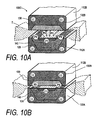
- FIG. 10A is a sectional view of the jaw structure of FIGS. 7-8 illustrating an initial step in a method of the invention wherein Rf current flow paths cross the engaged tissue to cause ohmic heating therein.
- FIG. 10B is a sectional view of the jaw structure of FIG. 10A depicting a subsequent step in a method of the invention with modulated Rf current flow paths in the engaged tissue.
- FIG. 10C is another sectional view similar to FIGS. 10A-10B depicting a step in a method of the invention wherein Rf current flow paths within an interior of a variable resistive matrix prevent sparking at a jaw engagement surface.
- FIG. 10D is another view similar to FIGS. 10A-10C depicting a step in a method of the invention wherein Rf current flow paths occur in different axial regions of the jaws depending on local jaw compression.
- FIG. 11 is a perspective view of an alternative high-compression jaw structure carrying 3D variable resistive matrix bodies that is adapted for one-step tissue welding and transection corresponding to the invention, the matrix bodies coupled to an Rf source via series and parallel circuits.
- FIG. 12 is a schematic sectional view of the jaw structure of FIG. 11 taken along line 12 - 12 of FIG. 11 showing the variable resistive matrices in each jaw together with the series and parallel circuits.
- FIG. 13 is an enlarged sectional view of a portion the jaw structure of FIGS. 11-12 showing the potential current paths in engaged tissue and the variable resistive 3D matrix bodies during operation.
- FIGS. 14A-14C are schematic sectional views of the jaw structure of FIGS. 11-13 with elongate jaws progressively engaging, welding and transecting a tissue bundle.
- FIG. 15 is a perspective view of a portion of an alternative jaw structure similar to that of FIGS. 11-13 with a variable resistive matrix having a pixelated configuration.
- FIG. 16 is an enlarged cut-away view of several pixels of the variable resistive matrix of FIG. 15 .
- FIG. 17A is a cut-away view similar to FIG. 16 illustrating a first step in a method of using the pixelated variable resistive matrix of FIG. 16 .
- FIG. 17B is another cut-away view illustrating a second step in a method of using the pixelated variable resistive matrix of FIG. 16 .
- FIG. 18 is a cut-away view of an alternative variable resistive matrix with PTCR polymeric pixels and polymeric field materials having different durometers for providing dynamic surface relief.
- FIG. 19 is a perspective view of an alternative jaw engagement surface with edge regions having a higher durometer or modulus than non-edge regions.
- FIG. 20 is a view of an alternative jaw engagement surface with an elevated edge region of a higher durometer or modulus.
- FIG. 21 is a view of an alternative pixelated matrix similar to that of FIG. 16 .
- FIG. 22 is a perspective view of an alternative jaw engagement surface with a resilient polymer component at an interior of the jaw.
- FIG. 23 is a view of an alternative pixelated matrix wherein the polymeric pixel composition and the field composition are of different PTCR materials.
- FIG. 24 is a view of an alternative matrix wherein the first and second PTCR compositions have a random distribution.
- FIG. 25 is a perspective view of an alternative jaw engagement surface with a plurality of spaced apart PTCR regions for creating thermal “staple-like” weld features in a tissue margin.
- FIG. 26 is a schematic view of an organ margin with a plurality of thermal “staple-like” welds that is enabled by the working end of FIG. 25 .
- Electrosurgical jaw structure with variable resistive matrices Various embodiments of the invention provide systems and methods to deliver energy to targeted tissue volumes in a controlled manner to thermally weld or seal targeted tissue. Particular embodiments provide systems and methods for contemporaneously (i) engaging tissue between paired jaws, (ii) delivering energy to the tissue, and (iii) optionally transecting the tissue to provide a “one-step” welding-transecting procedure. Many embodiments provide a jaw structure configured to engage and weld tissue bundles, that is bundles of disparate tissue types (e.g., fat, blood vessels, fascia, etc.). For the welding of tissue bundles, the jaw surfaces can be configured to apply differential energy levels to each different tissue type simultaneously. Related aspects of the invention provide an electrosurgical system that can apply differential energy levels across the jaws engagement surfaces with “smart” materials without the need for complex feedback circuitry coupled to thermocouples or other sensors in the jaw structure.
- tissue types e.g., fat, blood vessels, fascia, etc.
- FIG. 1 illustrates an exemplary forceps-type instrument 90 with a working end or electrosurgical jaw structure 100 A corresponding to the invention that comprises first (lower) jaw element 112 A and second (upper) jaw element 112 B that close or approximate about axis 115 that is straight or curved.
- the jaw elements can be of any curved or straight shape for open or endoscopic surgeries with scissors-type actions or with one or more cam mechanism as is known in the art.
- the jaws also can carry a sliding cutting blade as will be described below.
- FIG. 2 depicts a longitudinal sectional view of jaws 112 A and 112 B and an engaged tissue bundle T that contains, for example, insulative fat 118 , large blood vessels 120 and smaller embedded blood vessels 122 .
- the gap between the jaws is not-to-scale, and in an actual jaw structure the compressed tissue bundle T could be reduced to the thickness of a thin membrane.
- the tissue bundle would also contain fascia, ligamentous tissues and other tissues that would exhibit a wide range of hydration levels, electrolyte levels etc. that would locally alter tissue impedance, compressibility etc.
- tissue types e.g. bone, tendon, muscle, etc.
- jaws 112 A and 112 B can be configured to contemporaneously modulate energy densities across the various types of in the tissue bundle T according to the impedance of each engaged tissue type and region. Further, it is desirable to continuously modulate energy delivery to each tissue type as the region dynamically changes in hydration, impedance and geometry. As energy is delivered, the tissue will shrink as it dehydrates.
- FIG. 3 illustrates the tissue-engaging surfaces 124 A and 124 B of jaws 112 A and 112 B.
- the jaws each carry a three-dimensional (3D) temperature-responsive variable resistive body.
- the lower jaw 112 A carries variable resistive body indicated at 125 , also at times referred to herein as a positive temperature coefficient of resistance (PTC or PTCR) body or matrix.
- PTC or PTCR positive temperature coefficient of resistance
- variable resistive body 125 defines an axial dimension X and a cross-axial dimension Y about the tissue-engaging surface, as well as defining a substantial depth dimension Z that is orthogonal to the plane of the tissue-engaging surface 124 A.
- variable resistive body or matrix 125 has a selected thickness dimension in preferred embodiments to provide a multiplicity of varied local current flow paths through the matrix as it dynamically responds to adjacent ohmically heated tissue, as will be described below.
- the upper jaw 112 B in one preferred embodiment as in FIG. 3 carries variable resistive body 130 that again can have any suitable depth dimension.
- lower jaw 112 A has a structural component or body 132 A that is of a suitable electrical conductor material so that it functions as an electrode—that is indicated for convenience with a negative polarity ( ⁇ ).
- the upper jaw 112 B has structural component or body 132 B that is has the same polarity ( ⁇ ) as the lower jaw body.
- An electrically conductive member or electrode 140 is provided within variable resistive matrix 125 either at the tissue-engaging surface 124 A or proximate the surface as depicted in FIG. 3 .
- Both jaws optionally can have an insulative coating indicated at 142 at the exterior of lower jaw 112 A.
- variable resistive matrices 125 and 130 in lower jaw 112 A and upper jaw 112 B comprise a polyethylene or a medical grade silicone polymer that is doped with conductive particles (e.g., carbon).
- conductive particles e.g., carbon
- Polymer positive temperature coefficient materials are known in the field of overcurrent protection devices that will trip and become resistive when a selected trip current and temperature is exceeded.
- the temperature-responsive variable resistive materials for use in the invention are fabricated of a non-conductive polymer that exhibits two phases that define greater and lesser conductive states.
- the first phase is a crystalline or semi-crystalline state where the polymer molecules form long chains and are arranged in a more ordered architecture.
- the polymer is designed to transition to an at least partly amorphous phase from the crystalline state at a selected temperature range. In the amorphous state, the molecules are aligned more randomly, and there may be slight changes in material geometry at the macroscale.
- the non-conductive polymer is combined with a dispersed, highly conductive particles (e.g., carbon micro- or nanoparticles) to form a matrix.
- a dispersed, highly conductive particles e.g., carbon micro- or nanoparticles
- the carbon particles are packed into the crystalline boundaries and form many conductive paths across and through the matrix material.
- the polymer-carbon matrix is engineered to have a low resistance.
- FIG. 4A illustrates the positively-sloped impedance-temperature curve 130 M of an exemplary variable resistive matrix 130 of FIG. 3 .
- the jaw structure 100 A as in FIG. 3 is configured to engage tissue and apply Rf energy to the engaged tissue T to cause ohmic heating therein. After the tissue is elevated in temperature, heat is conducted from the engaged tissue T back to the variable resistive matrices 125 and 130 to thereby elevate temperatures in at least surfaces region of the matrices 125 and 130 . Details of the actual method of using the matrices to provide high temperature and low temperature process limits are described below. As long as the temperature increase in the matrix portion adjacent the ohmically heated tissue does not cause a phase change in the polymer, current can flow unimpeded through the matrix.
- the temperature of the matrix material When the temperature of the matrix material is elevated to a selected temperature, called a switching range herein, the temperature will cause a phase change in the polymer (see FIG. 4A ).
- the crystalline structure of the polymer will disappear, the polymer volume will expand, and the carbon chains that allow conduction across the matrix will be broken—resulting in an extraordinary increase in resistance.
- the polymer-carbon matrix can define a resistance measured in milliohms or ohms before the phase change. After the phase change, the matrix' resistance can be measured in megaohms. Current flow can be reduced accordingly, or terminated, which is used in particular manners corresponding to the invention to precisely control Rf energy densities in the engaged tissue.
- variable resistive body for example body 130 in the upper jaw, can spatially modulate Rf current flows in a dynamic manner wherein micron scale regions are conductive and adjacent micron scale regions are non-conductive in response to the temperature of engaged tissue.
- the polymer matrices of the invention may be temperature cycled several times in the fabrication process which appears to cause the material to have substantially resettable conductive paths.
- the matrix can also be treated in various processes (e.g., gamma, UV irradiation etc.) to cross-link the polymer or co-polymers of the matrix.
- polymer matrix 125 has at least two differentiated regions 144 and 145 that define different temperature-impedance curves as illustrated in FIG. 4B .
- the regions 144 a and 144 b (collectively 144 ) at the center of the lower jaw and the laterally-outward edge of the jaw are of a highly conductive matrix that will only terminate current flow therethrough at a high temperature, for example between 100° C. and 200° C. as shown in FIG. 4B .
- These regions 144 effectively function as the opposing polarity conductive electrodes as the regions 144 are in contact with the central first polarity conductor 140 and the second polarity jaw body 132 A.
- the lower jaw's matrix region 145 can also provide a plurality of slightly different regions 145 a and 145 b the have somewhat different base resistances and/or switching ranges as shown in FIG. 4B for reasons described below. In any event, matrix region 145 has a base resistance that somewhat higher than that of matrix 130 in the upper jaw 112 B.
- the jaw structure is coupled to voltage source 150 A (a radiofrequency generator) and controller 150 B for controlling duration of energy delivery and other Rf parameters ( FIG. 3 ). The manner in which matrices 125 and 130 operate to modulate energy densities in tissue will be described in greater detail below.
- the jaw structure 100 A corresponding to the invention utilized the two differently performing matrices 125 and 130 ( FIG. 3 ) in combination with the series and parallel circuitry of FIG. 5 to provide effective high and low process limits for temperatures and energy densities in the engaged tissue T. It has been found that such dynamic energy and temperature controls are optimal for creating uniform thermal effects in tissue to denature tissue proteins and to create high strength welds.
- the matrix 130 in upper jaw 112 B is engineered to exhibit unique temperature-impedance characteristics represented by the positively-sloped curve 130 M of FIG. 4B .
- This matrix 130 maintains a relatively low base resistance over a selected base temperature range with a dramatically increases resistance above a selected narrow temperature range (switching range) that can be any 1° to 10° range between about 50° C. and 200° C., and more preferably between about 70° C. and 120° C.
- a selected narrow temperature range switching range
- the matrix region 145 in lower jaw 112 A is designed to have an impedance-resistance curve exhibiting a higher initial base resistance (see FIG. 4B ).
- the matrix region 145 provides this higher base resistance over a similar temperature range as matrix 130 .
- the matrix 145 and its temperature-impedance curves ( 145 a , 145 b ) in FIG. 4B again exhibits a dramatically increasing resistance above its selected switching range, which can fall in the range described previously with reference to matrix 130 .
- FIG. 6A schematically depicts the manner in which the jaw structure 100 A of FIGS. 1 and 3 can self-modulate current flow among multiple paths—depending on the temperature of the engaged tissue and other electrical conduction parameters of the tissue to which the matrices 125 and 130 respond.
- FIG. 6A depicts a sectional view of the jaws 112 A and 112 B as in FIG. 3 engaging tissue T in phantom view.
- the tissue thickness is not to scale to allow a graphic representation of potential current paths.
- the working end 100 A of FIG. 6A has the ability to modulate current flow among multiple different paths through the tissue T as well as through the matrices 125 and 130 .
- FIG. 6A , and FIGS. 10A-10D in a simplified jaw illustrate four generally different flow paths, P 1 through P 4 , that effectively describe the general types of current flow paths that come into play in the self-modulating Rf ohmic heating method of the invention.
- the flow paths P 1 through P 4 do not indicate that current flows are dynamic and can be localized (conductive or non-conductive) across micron scale regions of the engagement surface of the matrices. The timing and potential switching between current paths during operation is described in more detail below.
- FIG. 6B graphically depicts important operational characteristics of the method corresponding to the invention, wherein Rf energy application to the engaged tissue is illustrated over a selected time interval.
- the horizontal axis indicates elapsed “time” after initiation of Rf energy delivery and ohmic heating, while the vertical axis indicates impedance ( ⁇ ) or power (P) for various curves.
- the curve marked I T represents the impedance of the engaged tissue over time.
- the curve marked P T represents the power (function of voltage and current) that is applied to the engaged tissue over time.
- the high current flow occurs in the (first) series component indicated at 152 A that engages the tissue. It is during this time interval, that may be only a fraction of a second to several seconds, that the temperature-responsive variable resistive body 130 in the upper jaw plays its major current limiting role in spatially modulating Rf paths in the highly compressed tissue to cause uniform ohmic heating over the engagement surfaces and within adjacent tissue regions.
- tissue impedance rises in curve I T a critical time interval in reached (indicated at 153 ; hatched area) wherein tissue desiccation and potential arcing is possible—which would cause potential tissue carbonization and destroy, reduce or eliminate weld strength.
- the commercially available Rf devices with feedback power control typically fail and cause tissue desiccation and charring.
- the feedback mechanisms such as a thermocouple or impedance monitoring, cannot respond rapidly and cannot provide a spatial response to direct current flow away from only the desiccated tissue.
- tissue impedance rises there is a rapid increase in voltage output from the generating source in this initial period after the source 150 A is turned on.
- the temperature-responsive variable resistive body 125 in the lower jaw 112 A plays its voltage or power limiting role to prevent potential arcs in the lowered-impedance tissue.
- the potential arcs in the tissue would occur principally in flow path P 2 (and related path P 3 ) wherein opposing polarity conductive portions are in closest proximity.
- the objective of the engagement surface and circuitry is to automatically limit power—to insure that an arc does not occur. In various embodiments, this is accomplished by the variable resistive body 125 in lower jaw 112 A to allow current to flow in paths P 4 directly between the opposing polarity body portions at an interior region of the jaw—and not within the tissue.
- the circuitry of the working end referring again to FIG.
- FIG. 10D illustrates that different spaced apart regions of engagement surfaces modulate current flow differently—depending on highly localized temperature and compression parameters of the engaged tissue.
- flow paths P 1 indicates potential Rf microcurrent flows directly through tissue T between first polarity electrode 140 and conductive region 145 and the low resistance matrix 130 of upper jaw 112 B that overlies the (opposing) second polarity jaw body 132 B. It can be understood that these current paths P 1 provide initial rapid ohmic heating of tissue.
- Flow paths P 2 indicate Rf current flow through tissue T between the highly conductive regions 144 a and 144 b that are laterally spaced apart in the lower jaw that are in contact with first polarity conductor 140 and second polarity jaw body 132 A, respectively.
- potential current flow paths indicated at P 3 and P 4 are unique to the invention and come operate to modulate ohmic heating in engaged tissue as its conductive parameters (impedance, temperature, and hydration) are dynamic during energy application.
- Potential flow paths P 3 represent potential microcurrent paths through a region of tissue between spaced apart surface portions of matrix 125 that engage such a tissue region.
- Potential current flow paths P 4 are at an interior of the jaw and the 3D matrix 125 wherein current can flow for voltage limiting purposes from electrode 140 across the matrix region 145 to the interior of the opposing polarity jaw body 132 A.
- FIG. 6A depicts the principles of the working end in a basic forceps-type jaw structure 100 A of FIGS. 1 and 3 .
- the same variable resistive matrices 125 and 130 can be provided in a jaw structure indicated at 100 B in FIGS. 7 and 8 that carries a blade for transecting the welded tissue.
- the same variable resistive matrices 125 and 130 can be carried in a one-step jaw structure that is described below ( FIGS. 11-12 ) wherein jaw closing, Rf energy delivery and tissue transection occur in a single operation.
- a forceps-type instrument is shown with a detachable cartridge 154 that carries a thin flexible blade member 155 that can be pushed by thumb slider 156 when the jaws are locked in a closed position.
- a blade cartridge was disclosed in co-pending U.S. patent application Ser. No. 10/443,974, filed May 22, 2003 titled Electrosurgical Working End with Replaceable Cartridges which is incorporated herein by this reference.
- FIG. 8 illustrates a cross section of the upper and lower jaws 112 A and 112 B with a central blade slot 160 for receiving the slidable, flexible blade member 155 .
- the jaw bodies carry variable resistive matrices 125 ′ and 130 ′ that are similar (or identical) to the matrices depicted in FIG. 3 .
- the lower jaw 112 B has a matrix 125 ′ that is simplified in that electrode 140 is exposed in the center of the jaw's engagement surface 124 A with a portion of the 3D matrix 125 ′ extending laterally on either side of blade slot 160 as well as within the interior of the jaw.
- matrix extends in a “U”-shape around the end of blade slot 160 to allow welding of engaged tissue around the end of a welded and transected tissue region.
- the working end 100 B of FIGS. 7-8 functions to modulate Rf energy application to tissue in between multiple potential paths as described above and depicted in FIG. 6A .
- FIG. 9 illustrates the working end 100 B of FIGS. 7-8 and again graphically depicts the potential Rf current paths in tissue and across regions of the variable resistive matrices.
- the current paths P 1 , P 2 and P 3 again represent potential paths in the engaged tissue T.
- the current paths P 4 represent paths within the interior regions of matrix 125 ′ between first polarity (+) surface conductor 140 and a second polarity ( ⁇ ) region of jaw body 132 A.
- FIGS. 10A-10D the sequential energy delivery phases of the method of the invention is graphically illustrated.
- the opposing jaws 112 A and 112 B are depicted engaging a tissue bundle T, and Rf energy application to tissue is modulated by matrices 125 and 130 between various paths P 1 -P 4 in the tissue to create a uniform temperature without desiccation or charring to provide an effective high strength weld.
- FIGS. 10A-10D illustrate a basic jaw structure 100 C similar to that of FIG. without a blade member, but it should be appreciated that a jaw 100 B with a reciprocal blade as in FIGS. 7-8 would create a weld by the same means of energy application and modulation.
- the engagement surface 124 A of FIGS. 10A-10D has the central conductive member or electrode 140 exposed in the surface (cf. FIGS. 7-9 ).
- FIG. 10A an initial energy application step is illustrated wherein tissue bundle T is engaged as the jaws apply compression and the surgeon applies Rf energy to the tissue.
- FIG. 10A illustrates that current flows are substantially through the tissue between the first polarity conductor 140 and the opposing matrix 130 and laterally-outward upper jaw 132 B as well to the second polarity lower jaw body 132 A, that is in paths P 1 and P 2 as depicted in FIGS. 3 and 9 .
- FIG. 10A depicts current flow that causes very high energy densities and very rapid ohmic heating in the engaged tissue T.
- the matrices 125 and 130 are, in effect, in a stand-by mode and are not yet operating to modulate flow paths of the microcurrents in the tissue.
- the matrix 130 in the upper jaw at ambient room temperature has a low base resistance (see FIG. 4B ) and allows a multiplicity of conductive flow paths all across and through the matrix 130 to the second polarity jaw body 132 B from the first polarity conductor 140 in the lower jaw through the tissue T.
- the ohmically heated tissue causes conductive heat transfer to the matrices 125 and 130 to heat at least the surface regions of both matrices.
- the ohmically heated tissue T dehydrates, changes its geometry by shrinking and exhibits an increased impedance.
- the variable resistive matrix 130 responds according to its selected temperature-impedance curve (see FIG. 4B ) wherein the material regulate and modulate flow paths P 1 of microcurrents therethrough.
- the switching range of the matrix can be between about 60° C. to 120° C. and is more preferably in the 70° C. to 90° C., range.
- the impedance of tissue regions will be substantially matched by the induced impedance of adjacent regions of matrix 130 , to thereby modulate current flow in paths P 1 between the jaws.
- the matrix 130 will prevent any possibility of arcs or sparks at the interface of jaw surfaces 124 A and 124 B with the engaged tissue since current flow will be eliminated before excessive high temperatures are reached about any region of the tissue-jaw interfaces. The prevention of such arcs eliminates the possibility of unwanted tissue charring.
- the ohmically heated tissue also will conduct heat back to matrix 125 in the lower jaw 112 A to elevate the lower matrix above its selected switching range, for example in the 70° C. to 90° C., range.
- the increased impedance of the tissue will first prevent microcurrent flows in paths P 1 as the upper jaw's matrix 130 is masked. At this point, there will remain the possibility of microcurrent flows in paths P 2 between the electrode 140 and the laterally-outward jaw body portion 132 A.
- the dehydrated tissue T typically will be compressed to a thin membrane which can increase its impedance in the most direct paths of current (P 1 and P 2 ) between the opposing polarity body portions.
- the reduction or termination of ohmic heating will cause slight cooling of the tissue and re-hydration of the tissue can occur due to inward fluid migration.
- the lower matrix 125 will respond by cooling and then by causing microcurrent flows in paths P 3 as indicated in FIG. 10B .
- the increase in ohmic heating is then localized is these lateral regions of the engaged tissue while the tissue impedance still masks the upper jaw matrix 130 .
- the engaged tissue may hydrates to allow current flows in paths P 1 and P 2 to cause additional ohmic tissue heating.
- the temperature responsive matrices will self-modulate ohmic energy densities in the tissue between the various potential flow paths.
- FIG. 10C indicates another potential flow path P 4 that can come into play if any voltage occurs that could cause an arc at the jaw-tissue interface.
- the energy can be dissipated by energy flows in the paths indicated at P 4 between the first polarity conductor 140 and the second polarity lower jaw body 132 A directly through the lower matrix 125 at the jaw's interior.
- FIGS. 10A-10C indicate generally how the temperature-responsive matrices 125 and 130 , at the tissue-engaging surfaces 124 A and 124 B, will modulate ohmic heating in the engaged adjacent tissue T. It should be appreciated that the energy modulation also occurs about very localized regions of the engaged tissue T that is made up of different tissue types as discussed in the text accompanying FIG. 2 . Thus as any local region of tissue impedance changes during ohmic heating, the local adjacent region of matrix 130 in the initial phase will move to an impedance matching level.
- FIG. 10D illustrates the pivoting jaw structure 100 C as applying higher compression to more proximal tissue regions and the jaws close and the tissue dehydrates and shrinks during energy delivery. It can be understood that ohmic heating is thus modulated by matrices 125 and 130 in the jaws' engagement surfaces to provide locally independent energy densities in discrete tissue regions depending on local tissue temperature and impedance—as well as tissue geometry.
- duration of energy application to create an effective weld can range between about 1 second and 20 seconds, and more preferably is between about 3 second and 15 seconds.
- FIGS. 11 and 12 another embodiment of jaw structure 200 is illustrated that carries cooperating variable resistive matrices as descried above.
- the upper and lower jaws 212 A and 212 B have respective engagement surfaces 224 A and 224 B that carry cooperating variable resistive matrices 125 and 130 as in the previous embodiments of FIGS. 3 , 6 , 8 and 9 .
- the jaw embodiment of FIGS. 11 and 12 differs in that it is adapted for “one-step” welding and transection of the engaged tissue.
- jaw structure 200 has an opening-closing mechanism that is capable of applying very high compressive forces on tissue on the basis of cam mechanisms with a reciprocating “I”-beam member 240 , wherein jaw closing occurs contemporaneous with Rf energy delivery.
- the slidable “I”-beam member 240 and the exterior jaw surfaces provide cam surfaces (i) for moving the jaw assembly to the (second) closed position to apply very high compressive forces, and (ii) for moving the jaws toward the (first) open position to apply substantially high opening forces for dissecting tissue. This feature allows the surgeon to insert the tip of the closed jaws into a dissectable tissue plane—and thereafter open the jaws to apply such dissecting forces against tissues. Many prior art instruments are spring-loaded toward the open position and may not be useful for dissecting tissue.
- the reciprocating “I”-beam member 240 is actuatable from the handle (not shown) of the instrument by any suitable mechanism, such as a lever arm, that is coupled to a proximal end of member 240 .
- the distal end portion 242 of reciprocating “I”-beam member 240 carries first (lower) and second (upper) continuous laterally-extending flange elements 244 A and 244 B that are coupled by an intermediate transverse element 245 .
- the flange elements 244 A and 244 B slide in a recessed slot portion 246 in each of the upper and lower jaws (see FIG.
- the transverse element 245 and blade edge 250 slide within channels 252 (collectively) in the paired first and second jaws 212 A and 212 B to thereby open and close the jaws.
- the transverse element 245 is adapted to transect tissue captured between the jaws with a sharp leading blade edge 250 ( FIG. 11 ).
- the “I”-beam 240 also is adapted to provide electrosurgical functionality as it transects tissue and has a polarity that matches that of the jaw bodies 232 A and 232 B which is slidably contacts.
- the first and second jaws 212 A and 212 B close about an engagement plane 255 wherein the tissue-engaging surface layers 224 A and 224 B that contact and deliver energy to engaged tissue T as described above.
- the jaws can have any suitable length with teeth or serrations 256 for gripping tissue ( FIG. 11 ).
- One preferred embodiment of FIG. 11 provides such teeth 156 at an inner portion of the jaws along channels 248 thus allowing for substantially smooth engagement surface layers 224 A and 224 B laterally outward of the tissue-gripping elements.
- the axial length of jaws 212 A and 212 B indicated at can be any suitable length depending on the anatomic structure targeted for transection and sealing and typically will range from about 10 mm. to 50 mm.
- the jaw assembly can apply very high compression over much longer lengths, for example up to about 200 mm., for resecting and sealing organs such as a lung or liver.
- the scope of the invention also covers jaw assemblies for an instrument used in micro-surgeries wherein the jaw length can be about 5.0 mm or less.
- FIGS. 11 and 12 it can be seen that the lower jaw 212 A has a variable resistive matrix 125 that has an edge portion 258 that (optionally) extends laterally over the outer edge of the jaw body 232 A.
- This matrix feature has been found useful in modulating Rf energy density in the margin of the treated tissue to create distinct region between welded tissue and unaffected tissue.
- the upper jaw's matrix 130 is positioned to extend slightly outward (dimension 262 ) from the upper jaw body 232 B.
- FIG. 13 illustrates that the jaw structure 200 of FIGS. 11 and 12 provides the multiplicity of flow paths P 1 -P 4 as described previously in FIGS. 10A-10D .
- the jaw structure 200 and variable resistive matrices of FIGS. 11 and 12 functions as described above with reference to FIGS. 3 , 6 , 8 , 9 and 10 A- 10 D.
- FIGS. 14A-14C graphically illustrate the one-step sealing and transection method of the invention.
- the jaw structure 200 of FIGS. 11 and 12 solve such problems by applying Rf energy contemporaneously with jaw closure. Initial Rf energy delivery will begin to dehydrate the engaged tissue T thus making it possible to compress the tissue to a thin membrane.
- the matrices 125 and 130 will modulate Rf ohmic heating axially along the length of the jaws to thereby insure that thin treated tissue regions in the proximal jaw are not being ohmically heated while more distal regions of the engaged tissue are receiving maximal ohmic heating. All the while, each tissue region containing a different tissue type will receive the optimal Rf energy density based on impedance matching with the adjacent region of a variable resistive matrix.
- FIGS. 14A-14C the jaws 212 A and 212 B are shown with greatly exaggerated flex characteristics to illustrate, in effect, a method of the invention.
- the “I”-beam 240 can compress the tissue T dramatically as it is progressively welded.
- a very small jaw structure 200 in a 5 mm. diameter device can chomp down on, weld and transect very thick tissue bundles that are initially up to 1 ⁇ 2 inch or even 1 inch thick.
- the highest ohmic heating progresses in a “front” across the tissue and is automatically modulated by the variable resistive matrices 125 and 130 and series-parallel circuitry as described above.
- the jaw structure 200 further allows the surgeon tactile feedback of the tissue welding process as the advancement of the “I”-beam” 240 indicates that the tissue is welded.
- This inventive method for welding tissue can be most accurately summarized as the microscale modulation of ohmic active heating in engaged tissue as depicted in FIGS. 10A-10D combined with the progressive macroscale application of ohmic heating as in FIGS. 14A-14C as the blade 245 transects the engaged tissue.
- the one-step welding and transecting functionality is provided by the high compression “I”-beam for jaw closure and tissue transection together with the cooperating variable resistive components 125 and 130 of the jaw structure.
- FIG. 15 illustrates a portion of an alternative working end 310 corresponding to the invention with first and second jaws 312 A and 312 B and respective tissue-engaging surfaces 324 A and 324 B in a jaw-closed position.
- the working end 310 in general, is similar to that illustrated in FIGS. 11-13 .
- the engagement surfaces again include variable resistive matrices of a polymeric material the exhibits a positive temperature coefficient of resistance (PTC or PTCR) effect.
- the lower jaw 312 A carries a microfabricated matrix 325 that is best described as a pixelated PTCR matrix.
- the upper jaw carries a matrix 330 that is similar to that described in previous embodiments together with an exposed electrode 335 in a central portion of the engagement surface 324 B.
- the jaw structure of FIG. 15 reverses the location of exposed electrode 335 from that illustrated in FIGS. 9 , 11 and 12 , with no change in functionality.
- the matrix 325 of lower jaw 312 A defines a plurality of polymeric composite PTCR pixels 340 (collectively) spaced apart in a field 342 comprising a field material 344 .
- pixels 340 can comprise a pixel array 340 ′.
- Each pixel 344 of array 340 ′ can be configured to be independently switchable depending upon the temperature of engaged tissue adjacent the pixel as is described herein.
- Field 342 is also described as a non-pixel field comprising a plurality of non-pixel portions 342 ′.
- field material 344 can comprise a substantially electrically insulative material such as a electrically insulative polymer or a ceramic, an electrically and thermally insulative material, a materially having a substantially fixed electrical resistance, or a material having a negative temperature coefficient of resistance (NTC or NTCR).
- field material 344 can comprise an electrically insulative polymer which in one embodiment can be the same polymer as pixels 340 , but with substantially no conductive filler.
- the PTCR pixels 340 are shown as having rectangular or polygonal shape at the engagement surface 324 A.
- pixels 340 can have any number of surface shapes or contours, for example convex, concave, curvilinear, etc. Also pixels 340 can have any highly elongated linear or curvilinear form at engagement surface 324 A.
- field material 344 is an electrically non-conductive polymer (e.g., a polyethylene, silicone, etc.) that has one or more material properties similar to that of the PTCR pixels 340 .
- material properties can include without limitation, Young's modulus, durometer (e.g., Shore A or Shore D rating) and the like.
- pixels 340 are shown as substantially square pixels in FIGS. 15 and 16 .
- PTCR pixels 340 can have any number of round, oval, rectangular or polygonal cross-sectional shapes including combinations thereof.
- the shapes of pixels 340 can be homogeneous or heterogeneous including two or more different shapes.
- the shape of pixels 340 can be configured to achieve selectable thermal, electrical and mechanical properties or a combination of properties (e.g., thermal or electoral conductivity, etc.) for matrix 325 and/or engagement surfaces 224 A and 224 B.
- smaller sized pixels can be employed to obtain a high resolution, finer or otherwise more precise spatial control of current paths and/or to have faster thermal response times (e.g. faster switching times or time constants) due to faster thermal conduction in smaller pixel areas.
- one portion of matrix 325 can be configured with a first pixel size or combination of pixel sizes to have a first time constant and a second portion can be configured with a second pixel size or combination of sizes to have a second time constant.
- the selected pixel size can be an average pixel size with a selected standard deviation.
- the combination of pixel sizes can be a range of pixel sizes, and can also include a bimodal or other multi-model distribution of pixel sizes.
- matrix 325 can include portions having different shaped pixels, for example a first portion having a first shaped pixel and a second portion having a second pixel shape.
- the matrix 325 can include combination of homogenous and heterogeneous pixel shape portion.
- the matrix can include one or more heterogeneous portions and a one or more homogenous portions. The placement and combination of such portions can be configured to produce selectable thermal, electrical and/or mechanical properties.
- the dimension C across a minor axis of a pixel 340 can range from about 1 micron to 1000 microns, and more preferably from about 50 to 500 microns.
- the thickness dimension D of the matrix 325 that corresponds to the height of pixels 340 can range from about 100 microns to 3 mm.
- the spacing E between the pixels 340 can range from about 5 to 1000 microns.
- the pixels 340 extend from the engagement surface 324 A through the full thickness of matrix 325 to contact the jaw body 312 A which functions as an electrode as it is coupled to electrosurgical energy source 150 A.
- the matrix can have a durometer in the range from about 20 to 95 Shore A range, or in the range from about 45-80 Shore D range.
- Shore A and Shore D hardness ratings encompass material properties (e.g. durometer, elasticity, etc.) that have been found useful in particular embodiments. However, they are exemplary and in other embodiments, different ranges can be used, e.g. greater than 95 Shore A or greater than 80 Shore D. They can also be converted to equivalent Young's modulus, IRHD values (International Rubber Hardness Degree) and the like.
- FIGS. 17A-17B illustrate the method of using the pixelated matrix 325 in at least one jaw of an electrosurgical instrument.
- the PTCR pixels 340 function as temperature responsive components as described above, but with the (i) temperature sensing functionality and (ii) the Rf energy delivery functionality being distributed to a plurality of discrete regions, or pixels, over the engagement surface 324 A.
- FIG. 17A depicts the step of energizing the working end wherein Rf current flows are indicated at P in tissue T as the current flows between the opposing polarity electrodes 312 A and 335 via the PTCR pixels 340 a - 340 d .
- each pixel 340 a - 340 d indicate current flow therethrough which is allowed at any time the pixel is below its switching range.
- electrical current cannot flow through the field portion 342 (Note change 344 in drawing to 342 ) of matrix 325 since it is a non-conductive polymer.
- Rf current tends to jump off “edges” of a conductor when interfacing with a less conductive media, such as tissue.
- the plurality of PTCR pixels 340 can be configured as a myriad of such “edges” to induce current to propagate from the engagement surface.
- PTCR pixels 340 can be utilized to control the induction and flow of current from the engagement surface to tissue.
- FIG. 17A it can be easily understood that alternating Rf current will then cause ohmic heating in the engaged tissue T, which is along the idealized current paths P in the tissue.
- the resolution of the PTCR pixels 340 can be specified to be sufficiently fine so that ohmic heating occurs in a substantially continuous and uniform manner across the dimension of the engagement surfaces 324 A and 324 B.
- the idealized current flow paths P indicate that the PTCR pixels 340 are below the switching range (the PTCR effect) of the polymeric composition thus causing Rf energy density, and resultant ohmic heating, in the engaged tissue T.
- the next step of the method relates to the use of the pixelated matrix 325 in its temperature responsive role to adjust its resistivity in response to adjacent tissue temperature.
- the region 350 of tissue T adjacent to pixels 340 a and 340 b is indicated by cross-hatching as being ohmically heated above the switching range of the PTCR pixels.
- the other tissue region 352 adjacent to pixels 340 c and 340 d still carries current flow in paths P and ohmic heating continues—but thermal effects remain below the switching range of the adjacent PTCR pixels 340 c and 340 d .
- tissue Such differential thermal effects in tissue caused by ohmic heating are the norm, as tissues differ greatly in hydration before Rf application, and dynamically change during the course of Rf application.
- the desiccation of tissue plays a major role in ohmic heating, and well as tissue type (i.e., collagenous tissue, fatty tissue, etc.).
- tissue type i.e., collagenous tissue, fatty tissue, etc.
- the highly ohmically heated tissue region 350 conducts heat back to the surface regions 355 of the pixels 340 a and 340 b thereby elevating these pixel surfaces 355 to above the switching range of the material.
- PTCR pixels 340 a and 340 b terminate current flow to the tissue.
- the pixels function as discrete “on-off switches” to either allow or disallow current flow therethrough to the immediately adjacent tissue.
- the working surface 324 A thus can be considered to provide micron-scale localized on-off control of Rf application to engaged tissue based on micron-scale local temperature sensing.
- These and related embodiments provide a means for controlling Rf application to tissue with highly spatially distributed temperature sensing and response—exactly at the engagement surface 324 A.
- this approach allows for a more rapid and spatially precise control of energy application resulting in more uniform thermal effects in the target tissue including more uniform heating and welding with a reduced incidence of desiccation and charring.
- embodiments of this method of thermal tissue treatment using pixilated PTCR materials to control energy application can be accomplished without thermocouples or feedback circuitry This approach differs markedly from other thermal sensing systems that may use a single sensor coupled to feedback circuitry and controller algorithms.
- each pixel 340 a - 340 b will respond and change temperature at and about the engagement surface 324 A.
- the actual “switched” region of each pixel 340 a - 340 b thus is indicated at 355 , wherein the temperature exceeds the PTCR material's switching range.
- the field material 344 is substantially thermally insulative so as to enhance the effect of causing the switched regions 355 of the pixels 340 (collectively) to remain as close as possible to the engagement surface 324 A.
- the insulative field material 344 preferably has a thermal conductivity of less than about 10 W/m-K which insures that it is not retaining heat to conduct back to the pixels.
- the field material 344 has a thermal conductivity of less than about 5 W/m-K, and more preferably less than about 2 W/m-K.
- the pixelated matrix 325 of FIGS. 15-17B can be microfabricated using suitable polymers by several different techniques collectively known as soft lithography.
- microtransfer molding can be used wherein a transparent, elastomeric polydimethylsiloxane (PDMS) stamp has patterned relief on its surface to generate features in the polymer.
- PDMS stamp is filled with a prepolymer or ceramic precursor and placed on a substrate. The material is cured and the stamp is removed.
- the technique generates features as small as 250 nm and is able to generate multilayer systems that can be used to fabricate the pixels and polymeric field in which the pixels reside.
- Replica molding is a similar process wherein a PDMS stamp is cast against a conventionally patterned master. A polyurethane or other polymer is then molded against the secondary PDMS master. In this way, multiple copies can be made without damaging the original master.
- the technique can replicate features as small as about 50 to 100 nm.
- Another process is known as micromolding in capillaries (MIMIC) wherein continuous channels are formed when a PDMS stamp is brought into conformal contact with a solid substrate. Then, capillary action fills the channels with a polymer precursor. The polymer is cured and the stamp is removed. MIMIC can generate features down to 1 ⁇ m in size.
- Solvent-assisted microcontact molding is also known wherein a small amount of solvent is spread on a patterned PDMS stamp and the stamp is placed on a polymer, such as photoresist. The solvent swells the polymer and causes it to expand to fill the surface relief of the stamp. Features as small as 100 nm have been produced. A background on soft lithography microfabrication is found in Xia and Whitesides, Annu. Rev. Mater. Sci. 1998 28:153-84.
- the polymer material comprising the matrix can be extruded using extrusion methods known in the art to disperse or otherwise provide the PTCR pixels 340 within a polymeric field material 344 .
- the extruded material then can be cut into selectable slices to make individual thin pixilated PTCR matrices.
- the extruded material can be also processed using a variety of polymer processing methods known in the art, e.g., calendaring, etc, to produce selectable matrix thickness or other matrix dimension.
- the pixel material can be co-extruded with field material.
- FIG. 18 illustrates an alternative embodiment of matrix 325 ′ wherein pixels 340 and the field material 344 having differing durometer and/or elastic moduli.
- the jaw engagement surfaces 324 A and 324 B are in a closed position with the engaged tissue T under very high compression developed by the translating beam 240 as can be understood from FIGS. 12 , 13 and 15 .
- the lower engagement surface 324 A of FIG. 18 it can be seen that the lower modulus composition 344 is more compressible about the interface with the tissue T.
- the spatially variable moduli in the engagement surface 324 A provides a dynamic form of tissue-gripping structure for grippably engaging the tissue T during modulated Rf application.
- the engagement surfaces provides a dynamic, projecting grip structure that provides for greater surface relief under high tissue compression, just when greater gripping is required.
- the instrument of FIGS. 12 , 13 and 15 can weld and transect tissue in “one-step”, and it is desirable to have a surface gripping structure that insures that the tissue does not slip laterally as it is being welded and transected. Further, it is believed that local recesses 356 of the low modulus polymer 344 in the engagement surface 324 A are beneficial during the tissue-welding process.
- the Young's modulus and/or durometer of the pixels 340 and the insulative field material 344 can be reversed.
- the pixels 340 can be configured to have a lower modulus and be more compressible than the field material 344 , which again will dynamically grip tissue and localize moisture in the transiently recessed portions.
- FIG. 19 further provides at least one edge region 360 of resilient engagement surface 324 A (e.g., pixels 340 and field material 344 ) in a material having a higher Young's modulus (or durometer) than the central region 362 of the surface.
- the upper jaw is not shown for clarity of illustration.
- FIG. 19 depicts the higher modulus outer edge region 360 engaging tissue (phantom view) about the jaw periphery while the central lower modulus region 362 of engagement surface 324 A is compressed under the strength of the jaw closing mechanism.
- the second or inner side 364 of the engagement surface 324 A of FIG. 19 also can have a higher modulus edge region (phantom view).
- first edge region 360 in its repose state is more elevated than the central region 362 of the engagement surface.
- first edge region 360 can have a zigzag or other similar angular form for enhanced gripping of tissue.
- the inner edge 364 of engagement surface 324 A (phantom view) also can be “elevated” (greater surface relief) in its repose state or can have a higher modulus than the central lower modulus region 362 .
- FIG. 21 is another embodiment of matrix 325 wherein the pixels 340 and polymeric field 344 are configured and molded in an alternative manner.
- the engagement surface 324 A again exposes the pixelated regions of a PTCR composition for sensing tissue temperature and on-off switching of Rf current flow in a pixel-by-pixel manner.
- the cross-sectional view of the matrix 325 illustrates that the PTCR pixels 340 can have a tapered form and extend from a continuous base portion 365 of the PTCR polymer.
- the insulative polymer field material 344 is then molded around the pixels 340 to provide the insulated region of the engagement surface about the spaced apart exposed pixels.
- FIG. 21 is another embodiment of matrix 325 wherein the pixels 340 and polymeric field 344 are configured and molded in an alternative manner.
- the engagement surface 324 A again exposes the pixelated regions of a PTCR composition for sensing tissue temperature and on-off switching of Rf current flow in a pixel-by-pixel manner.
- the matrix 325 of FIG. 21 also illustrates another optional component of the electrosurgical working end that comprises a resilient body 366 that comprises a compressible cushion underlying the matrix 325 .
- the resilient body 366 can be any rubber-like material that allows its compression so as to accommodate thicker tissue volumes engaged by the jaws 312 A and 312 B (see FIG. 15 ).
- the resilient body 366 also can be an open cell type of material in which case at least one vent 368 can be provided in the jaw to better allow compression and decompression of the body 366 .
- the resilient body 366 can be a conductively doped polymer, in order for the matrix 325 to conductively coupled with the jaw body 312 A.
- any other conductive clip can be provided to couple the interior of matrix 325 to the jaw body 312 A.
- FIG. 22 illustrates a working end that has an alternative resilient body 370 that can underlie the matrix 325 .
- the resilient body 370 has a cut-out shape to provide space for compression of the resilient material to better allow overall compression of matrix 325 in at least one jaw when engaging thick tissue volumes.
- the pixelated engagement surface 324 A can be formed of first and second differing polymeric PTCR compositions.
- the field PTCR composition 344 ′ can have a low switching range wherein it responds to a low temperature in the ohmically heated adjacent tissue to thereby switch off Rf current, for example in the 80° to the 120° C. range.
- the PTCR composition of the pixels indicated at 340 ′ has a higher switching range wherein it responds only to a higher temperature in the adjacent ohmically heated tissue to thereby switch off current, for example in the 120° to the 300° C. range.
- the use of two differently performing PTCR composites in an engagement surface 324 A has the advantage of rapidly elevating the ohmic heating in the engaged tissue T until the lower-switching matrix turns off, and thereafter functioning as described above with the higher-switching pixels 340 ′ providing controlled Rf application to the engaged tissue.
- the matrix in one or both engagement surfaces 324 A and 324 B can be a more random distribution of first and second PTCR compositions 380 and 382 as depicted in FIG. 24 .
- These first and second PTCR compositions 380 and 382 can respective first switching range between 80°-120° C., and a second switching range between 120°-300° C. as described above.
- the random spatial locations of the first and second PTCR compositions 380 and 382 can provide modulated energy application similar to that of the pixelated embodiments described above.
- the elastic moduli of the respective first and second PTCR compositions 380 and 382 can vary exactly as described above in the dimensionally ordered matrices.
- FIG. 25 illustrates another alternative jaw structure 385 with an engagement surface 324 A that includes a plurality of spaced apart PTCR regions 390 for creating thermal “staple-like” welds in a tissue margin.
- the polymeric composition 394 of the field is preferably an insulative polymer but can also be a second PTCR material as described above.
- the spaced apart PTCR regions 390 typically can have a higher modulus as described above.
- FIG. 26 is a schematic illustration of an organ 400 treated with the jaw structure 385 of FIG. 25 .
- the jaw structure would create a pattern of controllably shaped, controllably dimensioned and controllably spaced apart welds 402 in tissue, or along a transected tissue margin 404 , to provide a seal.
- This manner of treating tissue has the advantage of providing an intermittent weld or seal which will allow the tissue to retain more elasticity and flexibility after being sealed.
- Such an intermittent weld or seal also may be advantageous in thin or fragile tissues.
- the use of such an intermittent weld or seal can be used treating various body organs, such as lung resections, thin-walled veins, bowels and other hollow or tubular organs.
Landscapes
- Health & Medical Sciences (AREA)
- Surgery (AREA)
- Engineering & Computer Science (AREA)
- Life Sciences & Earth Sciences (AREA)
- Biomedical Technology (AREA)
- Otolaryngology (AREA)
- Nuclear Medicine, Radiotherapy & Molecular Imaging (AREA)
- Plasma & Fusion (AREA)
- Physics & Mathematics (AREA)
- Heart & Thoracic Surgery (AREA)
- Medical Informatics (AREA)
- Molecular Biology (AREA)
- Animal Behavior & Ethology (AREA)
- General Health & Medical Sciences (AREA)
- Public Health (AREA)
- Veterinary Medicine (AREA)
- Surgical Instruments (AREA)
Abstract
Description
Claims (22)
Priority Applications (2)
| Application Number | Priority Date | Filing Date | Title |
|---|---|---|---|
| US11/080,101 US7955331B2 (en) | 2004-03-12 | 2005-03-14 | Electrosurgical instrument and method of use |
| US13/101,182 US20110276045A1 (en) | 2004-03-12 | 2011-05-05 | Electrosurgical instrument and method of use |
Applications Claiming Priority (2)
| Application Number | Priority Date | Filing Date | Title |
|---|---|---|---|
| US55297804P | 2004-03-12 | 2004-03-12 | |
| US11/080,101 US7955331B2 (en) | 2004-03-12 | 2005-03-14 | Electrosurgical instrument and method of use |
Related Child Applications (1)
| Application Number | Title | Priority Date | Filing Date |
|---|---|---|---|
| US13/101,182 Continuation US20110276045A1 (en) | 2004-03-12 | 2011-05-05 | Electrosurgical instrument and method of use |
Publications (2)
| Publication Number | Publication Date |
|---|---|
| US20050203507A1 US20050203507A1 (en) | 2005-09-15 |
| US7955331B2 true US7955331B2 (en) | 2011-06-07 |
Family
ID=34922423
Family Applications (2)
| Application Number | Title | Priority Date | Filing Date |
|---|---|---|---|
| US11/080,101 Active 2027-10-03 US7955331B2 (en) | 2004-03-12 | 2005-03-14 | Electrosurgical instrument and method of use |
| US13/101,182 Abandoned US20110276045A1 (en) | 2004-03-12 | 2011-05-05 | Electrosurgical instrument and method of use |
Family Applications After (1)
| Application Number | Title | Priority Date | Filing Date |
|---|---|---|---|
| US13/101,182 Abandoned US20110276045A1 (en) | 2004-03-12 | 2011-05-05 | Electrosurgical instrument and method of use |
Country Status (1)
| Country | Link |
|---|---|
| US (2) | US7955331B2 (en) |
Cited By (214)
| Publication number | Priority date | Publication date | Assignee | Title |
|---|---|---|---|---|
| US20090204112A1 (en) * | 2008-02-11 | 2009-08-13 | Expandoheat, Llc | Appraratus and method for vessel sealing and tissue coagulation |
| US20100274244A1 (en) * | 2009-04-24 | 2010-10-28 | Tyco Healthcare Group Lp | Electrosurgical Tissue Sealer and Cutter |
| US20110087209A1 (en) * | 2009-10-09 | 2011-04-14 | Ethicon Endo-Surgery, Inc. | Surgical instrument for transmitting energy to tissue comprising steam control paths |
| US20120012636A1 (en) * | 2010-07-14 | 2012-01-19 | Ethicon Endo-Surgery, Inc. | Surgical instruments with electrodes |
| USD680220S1 (en) | 2012-01-12 | 2013-04-16 | Coviden IP | Slider handle for laparoscopic device |
| US8454602B2 (en) | 2009-05-07 | 2013-06-04 | Covidien Lp | Apparatus, system, and method for performing an electrosurgical procedure |
| US8453906B2 (en) | 2010-07-14 | 2013-06-04 | Ethicon Endo-Surgery, Inc. | Surgical instruments with electrodes |
| US8496682B2 (en) | 2010-04-12 | 2013-07-30 | Ethicon Endo-Surgery, Inc. | Electrosurgical cutting and sealing instruments with cam-actuated jaws |
| US8523898B2 (en) | 2009-07-08 | 2013-09-03 | Covidien Lp | Endoscopic electrosurgical jaws with offset knife |
| US8535311B2 (en) | 2010-04-22 | 2013-09-17 | Ethicon Endo-Surgery, Inc. | Electrosurgical instrument comprising closing and firing systems |
| US8568444B2 (en) | 2008-10-03 | 2013-10-29 | Covidien Lp | Method of transferring rotational motion in an articulating surgical instrument |
| US8574231B2 (en) | 2009-10-09 | 2013-11-05 | Ethicon Endo-Surgery, Inc. | Surgical instrument for transmitting energy to tissue comprising a movable electrode or insulator |
| US8591506B2 (en) | 1998-10-23 | 2013-11-26 | Covidien Ag | Vessel sealing system |
| US8597296B2 (en) | 2003-11-17 | 2013-12-03 | Covidien Ag | Bipolar forceps having monopolar extension |
| US8628529B2 (en) | 2010-10-26 | 2014-01-14 | Ethicon Endo-Surgery, Inc. | Surgical instrument with magnetic clamping force |
| US8715277B2 (en) | 2010-12-08 | 2014-05-06 | Ethicon Endo-Surgery, Inc. | Control of jaw compression in surgical instrument having end effector with opposing jaw members |
| US8747404B2 (en) | 2009-10-09 | 2014-06-10 | Ethicon Endo-Surgery, Inc. | Surgical instrument for transmitting energy to tissue comprising non-conductive grasping portions |
| US8753338B2 (en) | 2010-06-10 | 2014-06-17 | Ethicon Endo-Surgery, Inc. | Electrosurgical instrument employing a thermal management system |
| US8764747B2 (en) | 2010-06-10 | 2014-07-01 | Ethicon Endo-Surgery, Inc. | Electrosurgical instrument comprising sequentially activated electrodes |
| US8834518B2 (en) | 2010-04-12 | 2014-09-16 | Ethicon Endo-Surgery, Inc. | Electrosurgical cutting and sealing instruments with cam-actuated jaws |
| US8852228B2 (en) | 2009-01-13 | 2014-10-07 | Covidien Lp | Apparatus, system, and method for performing an electrosurgical procedure |
| US8888776B2 (en) | 2010-06-09 | 2014-11-18 | Ethicon Endo-Surgery, Inc. | Electrosurgical instrument employing an electrode |
| US8898888B2 (en) | 2009-09-28 | 2014-12-02 | Covidien Lp | System for manufacturing electrosurgical seal plates |
| US8939975B2 (en) | 2012-07-17 | 2015-01-27 | Covidien Lp | Gap control via overmold teeth and hard stops |
| US8939974B2 (en) | 2009-10-09 | 2015-01-27 | Ethicon Endo-Surgery, Inc. | Surgical instrument comprising first and second drive systems actuatable by a common trigger mechanism |
| US8979843B2 (en) | 2010-07-23 | 2015-03-17 | Ethicon Endo-Surgery, Inc. | Electrosurgical cutting and sealing instrument |
| US9005199B2 (en) | 2010-06-10 | 2015-04-14 | Ethicon Endo-Surgery, Inc. | Heat management configurations for controlling heat dissipation from electrosurgical instruments |
| US9011437B2 (en) | 2010-07-23 | 2015-04-21 | Ethicon Endo-Surgery, Inc. | Electrosurgical cutting and sealing instrument |
| US9028493B2 (en) | 2009-09-18 | 2015-05-12 | Covidien Lp | In vivo attachable and detachable end effector assembly and laparoscopic surgical instrument and methods therefor |
| US9044243B2 (en) | 2011-08-30 | 2015-06-02 | Ethcon Endo-Surgery, Inc. | Surgical cutting and fastening device with descendible second trigger arrangement |
| US9113940B2 (en) | 2011-01-14 | 2015-08-25 | Covidien Lp | Trigger lockout and kickback mechanism for surgical instruments |
| US9113897B2 (en) | 2012-01-23 | 2015-08-25 | Covidien Lp | Partitioned surgical instrument |
| US20150250526A1 (en) * | 2011-06-22 | 2015-09-10 | Covidien Lp | Forceps |
| US9149324B2 (en) | 2010-07-08 | 2015-10-06 | Ethicon Endo-Surgery, Inc. | Surgical instrument comprising an articulatable end effector |
| US9192431B2 (en) | 2010-07-23 | 2015-11-24 | Ethicon Endo-Surgery, Inc. | Electrosurgical cutting and sealing instrument |
| US9204918B2 (en) | 2011-09-28 | 2015-12-08 | RELIGN Corporation | Medical ablation system and method of use |
| US9247983B2 (en) | 2011-11-14 | 2016-02-02 | Arqos Surgical, Inc. | Medical instrument and method of use |
| US9259265B2 (en) | 2011-07-22 | 2016-02-16 | Ethicon Endo-Surgery, Llc | Surgical instruments for tensioning tissue |
| US9265926B2 (en) | 2013-11-08 | 2016-02-23 | Ethicon Endo-Surgery, Llc | Electrosurgical devices |
| US9271783B2 (en) | 2012-07-17 | 2016-03-01 | Covidien Lp | End-effector assembly including a pressure-sensitive layer disposed on an electrode |
| US9277954B2 (en) | 2011-03-21 | 2016-03-08 | Arqos Surgical, Inc. | Medical ablation system and method of use |
| US9283027B2 (en) | 2011-10-24 | 2016-03-15 | Ethicon Endo-Surgery, Llc | Battery drain kill feature in a battery powered device |
| US20160074095A1 (en) * | 2014-09-15 | 2016-03-17 | Ethicon Endo-Surgery, Inc. | Methods and devices for creating thermal zones within an electrosurgical instrument |
| US9295514B2 (en) | 2013-08-30 | 2016-03-29 | Ethicon Endo-Surgery, Llc | Surgical devices with close quarter articulation features |
| US9375232B2 (en) | 2010-03-26 | 2016-06-28 | Ethicon Endo-Surgery, Llc | Surgical cutting and sealing instrument with reduced firing force |
| US9408660B2 (en) | 2014-01-17 | 2016-08-09 | Ethicon Endo-Surgery, Llc | Device trigger dampening mechanism |
| US9445863B2 (en) | 2013-03-15 | 2016-09-20 | Gyrus Acmi, Inc. | Combination electrosurgical device |
| US9452011B2 (en) | 2013-03-15 | 2016-09-27 | Gyrus Acmi, Inc. | Combination electrosurgical device |
| US9456864B2 (en) | 2010-05-17 | 2016-10-04 | Ethicon Endo-Surgery, Llc | Surgical instruments and end effectors therefor |
| US9492224B2 (en) | 2012-09-28 | 2016-11-15 | EthiconEndo-Surgery, LLC | Multi-function bi-polar forceps |
| US9526565B2 (en) | 2013-11-08 | 2016-12-27 | Ethicon Endo-Surgery, Llc | Electrosurgical devices |
| US9554846B2 (en) | 2010-10-01 | 2017-01-31 | Ethicon Endo-Surgery, Llc | Surgical instrument with jaw member |
| US9554854B2 (en) | 2014-03-18 | 2017-01-31 | Ethicon Endo-Surgery, Llc | Detecting short circuits in electrosurgical medical devices |
| US9585675B1 (en) | 2015-10-23 | 2017-03-07 | RELIGN Corporation | Arthroscopic devices and methods |
| US9603656B1 (en) | 2015-10-23 | 2017-03-28 | RELIGN Corporation | Arthroscopic devices and methods |
| US9610091B2 (en) | 2010-04-12 | 2017-04-04 | Ethicon Endo-Surgery, Llc | Electrosurgical cutting and sealing instruments with jaws having a parallel closure motion |
| US9681913B2 (en) | 2015-04-21 | 2017-06-20 | RELIGN Corporation | Arthroscopic devices and methods |
| US9700333B2 (en) | 2014-06-30 | 2017-07-11 | Ethicon Llc | Surgical instrument with variable tissue compression |
| US9707028B2 (en) | 2014-08-20 | 2017-07-18 | Gyrus Acmi, Inc. | Multi-mode combination electrosurgical device |
| US9737355B2 (en) | 2014-03-31 | 2017-08-22 | Ethicon Llc | Controlling impedance rise in electrosurgical medical devices |
| US9757186B2 (en) | 2014-04-17 | 2017-09-12 | Ethicon Llc | Device status feedback for bipolar tissue spacer |
| US9763730B2 (en) | 2013-03-15 | 2017-09-19 | Gyrus Acmi, Inc. | Electrosurgical instrument |
| US9782216B2 (en) | 2015-03-23 | 2017-10-10 | Gyrus Acmi, Inc. | Medical forceps with vessel transection capability |
| US9795436B2 (en) | 2014-01-07 | 2017-10-24 | Ethicon Llc | Harvesting energy from a surgical generator |
| US9814514B2 (en) | 2013-09-13 | 2017-11-14 | Ethicon Llc | Electrosurgical (RF) medical instruments for cutting and coagulating tissue |
| US9848937B2 (en) | 2014-12-22 | 2017-12-26 | Ethicon Llc | End effector with detectable configurations |
| US9861428B2 (en) | 2013-09-16 | 2018-01-09 | Ethicon Llc | Integrated systems for electrosurgical steam or smoke control |
| US9872725B2 (en) | 2015-04-29 | 2018-01-23 | Ethicon Llc | RF tissue sealer with mode selection |
| US9877776B2 (en) | 2014-08-25 | 2018-01-30 | Ethicon Llc | Simultaneous I-beam and spring driven cam jaw closure mechanism |
| US9901389B2 (en) | 2013-03-15 | 2018-02-27 | Gyrus Acmi, Inc. | Offset forceps |
| US9901388B2 (en) | 2013-03-15 | 2018-02-27 | Gyrus Acmi, Inc. | Hand switched combined electrosurgical monopolar and bipolar device |
| US9913680B2 (en) | 2014-04-15 | 2018-03-13 | Ethicon Llc | Software algorithms for electrosurgical instruments |
| US10004556B2 (en) | 2013-05-10 | 2018-06-26 | Corinth MedTech, Inc. | Tissue resecting devices and methods |
| US10022140B2 (en) | 2016-02-04 | 2018-07-17 | RELIGN Corporation | Arthroscopic devices and methods |
| US10080606B2 (en) | 2014-09-17 | 2018-09-25 | Covidien Lp | Method of forming a member of an end effector |
| US10092310B2 (en) | 2014-03-27 | 2018-10-09 | Ethicon Llc | Electrosurgical devices |
| US10092348B2 (en) | 2014-12-22 | 2018-10-09 | Ethicon Llc | RF tissue sealer, shear grip, trigger lock mechanism and energy activation |
| US10111699B2 (en) | 2014-12-22 | 2018-10-30 | Ethicon Llc | RF tissue sealer, shear grip, trigger lock mechanism and energy activation |
| US10117667B2 (en) | 2010-02-11 | 2018-11-06 | Ethicon Llc | Control systems for ultrasonically powered surgical instruments |
| US10117702B2 (en) | 2015-04-10 | 2018-11-06 | Ethicon Llc | Surgical generator systems and related methods |
| US10130410B2 (en) | 2015-04-17 | 2018-11-20 | Ethicon Llc | Electrosurgical instrument including a cutting member decouplable from a cutting member trigger |
| US10154852B2 (en) | 2015-07-01 | 2018-12-18 | Ethicon Llc | Ultrasonic surgical blade with improved cutting and coagulation features |
| US10159524B2 (en) | 2014-12-22 | 2018-12-25 | Ethicon Llc | High power battery powered RF amplifier topology |
| US10172669B2 (en) | 2009-10-09 | 2019-01-08 | Ethicon Llc | Surgical instrument comprising an energy trigger lockout |
| US10179022B2 (en) | 2015-12-30 | 2019-01-15 | Ethicon Llc | Jaw position impedance limiter for electrosurgical instrument |
| US10194976B2 (en) | 2014-08-25 | 2019-02-05 | Ethicon Llc | Lockout disabling mechanism |
| US10194972B2 (en) | 2014-08-26 | 2019-02-05 | Ethicon Llc | Managing tissue treatment |
| US10194973B2 (en) | 2015-09-30 | 2019-02-05 | Ethicon Llc | Generator for digitally generating electrical signal waveforms for electrosurgical and ultrasonic surgical instruments |
| US10201382B2 (en) | 2009-10-09 | 2019-02-12 | Ethicon Llc | Surgical generator for ultrasonic and electrosurgical devices |
| US10226273B2 (en) | 2013-03-14 | 2019-03-12 | Ethicon Llc | Mechanical fasteners for use with surgical energy devices |
| US10245065B2 (en) | 2007-11-30 | 2019-04-02 | Ethicon Llc | Ultrasonic surgical blades |
| US10245064B2 (en) | 2016-07-12 | 2019-04-02 | Ethicon Llc | Ultrasonic surgical instrument with piezoelectric central lumen transducer |
| US10251696B2 (en) | 2001-04-06 | 2019-04-09 | Covidien Ag | Vessel sealer and divider with stop members |
| US10251664B2 (en) | 2016-01-15 | 2019-04-09 | Ethicon Llc | Modular battery powered handheld surgical instrument with multi-function motor via shifting gear assembly |
| US10258404B2 (en) | 2014-04-24 | 2019-04-16 | Gyrus, ACMI, Inc. | Partially covered jaw electrodes |
| US10278721B2 (en) | 2010-07-22 | 2019-05-07 | Ethicon Llc | Electrosurgical instrument with separate closure and cutting members |
| USD847990S1 (en) | 2016-08-16 | 2019-05-07 | Ethicon Llc | Surgical instrument |
| US10285724B2 (en) | 2014-07-31 | 2019-05-14 | Ethicon Llc | Actuation mechanisms and load adjustment assemblies for surgical instruments |
| US10285723B2 (en) | 2016-08-09 | 2019-05-14 | Ethicon Llc | Ultrasonic surgical blade with improved heel portion |
| US10299810B2 (en) | 2010-02-11 | 2019-05-28 | Ethicon Llc | Rotatable cutting implements with friction reducing material for ultrasonic surgical instruments |
| US10314638B2 (en) | 2015-04-07 | 2019-06-11 | Ethicon Llc | Articulating radio frequency (RF) tissue seal with articulating state sensing |
| US10321950B2 (en) | 2015-03-17 | 2019-06-18 | Ethicon Llc | Managing tissue treatment |
| US10335182B2 (en) | 2012-06-29 | 2019-07-02 | Ethicon Llc | Surgical instruments with articulating shafts |
| US10335183B2 (en) | 2012-06-29 | 2019-07-02 | Ethicon Llc | Feedback devices for surgical control systems |
| US10335614B2 (en) | 2008-08-06 | 2019-07-02 | Ethicon Llc | Devices and techniques for cutting and coagulating tissue |
| US10342602B2 (en) | 2015-03-17 | 2019-07-09 | Ethicon Llc | Managing tissue treatment |
| US10357303B2 (en) | 2015-06-30 | 2019-07-23 | Ethicon Llc | Translatable outer tube for sealing using shielded lap chole dissector |
| US10376305B2 (en) | 2016-08-05 | 2019-08-13 | Ethicon Llc | Methods and systems for advanced harmonic energy |
| US10398466B2 (en) | 2007-07-27 | 2019-09-03 | Ethicon Llc | Ultrasonic end effectors with increased active length |
| US10420580B2 (en) | 2016-08-25 | 2019-09-24 | Ethicon Llc | Ultrasonic transducer for surgical instrument |
| US10420579B2 (en) | 2007-07-31 | 2019-09-24 | Ethicon Llc | Surgical instruments |
| US10426507B2 (en) | 2007-07-31 | 2019-10-01 | Ethicon Llc | Ultrasonic surgical instruments |
| US10441345B2 (en) | 2009-10-09 | 2019-10-15 | Ethicon Llc | Surgical generator for ultrasonic and electrosurgical devices |
| US10441308B2 (en) | 2007-11-30 | 2019-10-15 | Ethicon Llc | Ultrasonic surgical instrument blades |
| US10441310B2 (en) | 2012-06-29 | 2019-10-15 | Ethicon Llc | Surgical instruments with curved section |
| US10456193B2 (en) | 2016-05-03 | 2019-10-29 | Ethicon Llc | Medical device with a bilateral jaw configuration for nerve stimulation |
| US10463421B2 (en) | 2014-03-27 | 2019-11-05 | Ethicon Llc | Two stage trigger, clamp and cut bipolar vessel sealer |
| US10485607B2 (en) | 2016-04-29 | 2019-11-26 | Ethicon Llc | Jaw structure with distal closure for electrosurgical instruments |
| US10517627B2 (en) | 2012-04-09 | 2019-12-31 | Ethicon Llc | Switch arrangements for ultrasonic surgical instruments |
| US10524852B1 (en) | 2014-03-28 | 2020-01-07 | Ethicon Llc | Distal sealing end effector with spacers |
| US10524872B2 (en) | 2012-06-29 | 2020-01-07 | Ethicon Llc | Closed feedback control for electrosurgical device |
| US10531910B2 (en) | 2007-07-27 | 2020-01-14 | Ethicon Llc | Surgical instruments |
| US10537352B2 (en) | 2004-10-08 | 2020-01-21 | Ethicon Llc | Tissue pads for use with surgical instruments |
| US10543008B2 (en) | 2012-06-29 | 2020-01-28 | Ethicon Llc | Ultrasonic surgical instruments with distally positioned jaw assemblies |
| US10555769B2 (en) | 2016-02-22 | 2020-02-11 | Ethicon Llc | Flexible circuits for electrosurgical instrument |
| US10575892B2 (en) | 2015-12-31 | 2020-03-03 | Ethicon Llc | Adapter for electrical surgical instruments |
| US10595930B2 (en) | 2015-10-16 | 2020-03-24 | Ethicon Llc | Electrode wiping surgical device |
| US10595889B2 (en) | 2016-04-11 | 2020-03-24 | RELIGN Corporation | Arthroscopic devices and methods |
| US10595929B2 (en) | 2015-03-24 | 2020-03-24 | Ethicon Llc | Surgical instruments with firing system overload protection mechanisms |
| US10603117B2 (en) | 2017-06-28 | 2020-03-31 | Ethicon Llc | Articulation state detection mechanisms |
| US10603064B2 (en) | 2016-11-28 | 2020-03-31 | Ethicon Llc | Ultrasonic transducer |
| US10639092B2 (en) | 2014-12-08 | 2020-05-05 | Ethicon Llc | Electrode configurations for surgical instruments |
| US10646269B2 (en) | 2016-04-29 | 2020-05-12 | Ethicon Llc | Non-linear jaw gap for electrosurgical instruments |
| US10667834B2 (en) | 2017-11-02 | 2020-06-02 | Gyrus Acmi, Inc. | Bias device for biasing a gripping device with a shuttle on a central body |
| US10688321B2 (en) | 2009-07-15 | 2020-06-23 | Ethicon Llc | Ultrasonic surgical instruments |
| US10702329B2 (en) | 2016-04-29 | 2020-07-07 | Ethicon Llc | Jaw structure with distal post for electrosurgical instruments |
| US10709906B2 (en) | 2009-05-20 | 2020-07-14 | Ethicon Llc | Coupling arrangements and methods for attaching tools to ultrasonic surgical instruments |
| US10716615B2 (en) | 2016-01-15 | 2020-07-21 | Ethicon Llc | Modular battery powered handheld surgical instrument with curved end effectors having asymmetric engagement between jaw and blade |
| US10722261B2 (en) | 2007-03-22 | 2020-07-28 | Ethicon Llc | Surgical instruments |
| US10729494B2 (en) | 2012-02-10 | 2020-08-04 | Ethicon Llc | Robotically controlled surgical instrument |
| US10751117B2 (en) | 2016-09-23 | 2020-08-25 | Ethicon Llc | Electrosurgical instrument with fluid diverter |
| US10765470B2 (en) | 2015-06-30 | 2020-09-08 | Ethicon Llc | Surgical system with user adaptable techniques employing simultaneous energy modalities based on tissue parameters |
| US10779848B2 (en) | 2006-01-20 | 2020-09-22 | Ethicon Llc | Ultrasound medical instrument having a medical ultrasonic blade |
| US10779845B2 (en) | 2012-06-29 | 2020-09-22 | Ethicon Llc | Ultrasonic surgical instruments with distally positioned transducers |
| US10799284B2 (en) | 2017-03-15 | 2020-10-13 | Ethicon Llc | Electrosurgical instrument with textured jaws |
| US10820920B2 (en) | 2017-07-05 | 2020-11-03 | Ethicon Llc | Reusable ultrasonic medical devices and methods of their use |
| US10828057B2 (en) | 2007-03-22 | 2020-11-10 | Ethicon Llc | Ultrasonic surgical instruments |
| US10828059B2 (en) | 2007-10-05 | 2020-11-10 | Ethicon Llc | Ergonomic surgical instruments |
| US10835768B2 (en) | 2010-02-11 | 2020-11-17 | Ethicon Llc | Dual purpose surgical instrument for cutting and coagulating tissue |
| US10835307B2 (en) | 2001-06-12 | 2020-11-17 | Ethicon Llc | Modular battery powered handheld surgical instrument containing elongated multi-layered shaft |
| US10842580B2 (en) | 2012-06-29 | 2020-11-24 | Ethicon Llc | Ultrasonic surgical instruments with control mechanisms |
| US10842522B2 (en) | 2016-07-15 | 2020-11-24 | Ethicon Llc | Ultrasonic surgical instruments having offset blades |
| US10856934B2 (en) | 2016-04-29 | 2020-12-08 | Ethicon Llc | Electrosurgical instrument with electrically conductive gap setting and tissue engaging members |
| US10856896B2 (en) | 2005-10-14 | 2020-12-08 | Ethicon Llc | Ultrasonic device for cutting and coagulating |
| US10874418B2 (en) | 2004-02-27 | 2020-12-29 | Ethicon Llc | Ultrasonic surgical shears and method for sealing a blood vessel using same |
| US10893883B2 (en) | 2016-07-13 | 2021-01-19 | Ethicon Llc | Ultrasonic assembly for use with ultrasonic surgical instruments |
| US10898256B2 (en) | 2015-06-30 | 2021-01-26 | Ethicon Llc | Surgical system with user adaptable techniques based on tissue impedance |
| US10912580B2 (en) | 2013-12-16 | 2021-02-09 | Ethicon Llc | Medical device |
| US10952788B2 (en) | 2015-06-30 | 2021-03-23 | Ethicon Llc | Surgical instrument with user adaptable algorithms |
| US10952759B2 (en) | 2016-08-25 | 2021-03-23 | Ethicon Llc | Tissue loading of a surgical instrument |
| US10959771B2 (en) | 2015-10-16 | 2021-03-30 | Ethicon Llc | Suction and irrigation sealing grasper |
| US10959806B2 (en) | 2015-12-30 | 2021-03-30 | Ethicon Llc | Energized medical device with reusable handle |
| US10966780B2 (en) | 2012-04-17 | 2021-04-06 | Covidien Lp | Electrosurgical instrument having a coated electrode |
| US10987156B2 (en) | 2016-04-29 | 2021-04-27 | Ethicon Llc | Electrosurgical instrument with electrically conductive gap setting member and electrically insulative tissue engaging members |
| US10987123B2 (en) | 2012-06-28 | 2021-04-27 | Ethicon Llc | Surgical instruments with articulating shafts |
| US10993763B2 (en) | 2012-06-29 | 2021-05-04 | Ethicon Llc | Lockout mechanism for use with robotic electrosurgical device |
| US11020140B2 (en) | 2015-06-17 | 2021-06-01 | Cilag Gmbh International | Ultrasonic surgical blade for use with ultrasonic surgical instruments |
| US11033325B2 (en) | 2017-02-16 | 2021-06-15 | Cilag Gmbh International | Electrosurgical instrument with telescoping suction port and debris cleaner |
| US11033323B2 (en) | 2017-09-29 | 2021-06-15 | Cilag Gmbh International | Systems and methods for managing fluid and suction in electrosurgical systems |
| US11033292B2 (en) | 2013-12-16 | 2021-06-15 | Cilag Gmbh International | Medical device |
| US11051873B2 (en) | 2015-06-30 | 2021-07-06 | Cilag Gmbh International | Surgical system with user adaptable techniques employing multiple energy modalities based on tissue parameters |
| US11058447B2 (en) | 2007-07-31 | 2021-07-13 | Cilag Gmbh International | Temperature controlled ultrasonic surgical instruments |
| US11065023B2 (en) | 2017-03-17 | 2021-07-20 | RELIGN Corporation | Arthroscopic devices and methods |
| US11090103B2 (en) | 2010-05-21 | 2021-08-17 | Cilag Gmbh International | Medical device |
| US11090104B2 (en) | 2009-10-09 | 2021-08-17 | Cilag Gmbh International | Surgical generator for ultrasonic and electrosurgical devices |
| US11129670B2 (en) | 2016-01-15 | 2021-09-28 | Cilag Gmbh International | Modular battery powered handheld surgical instrument with selective application of energy based on button displacement, intensity, or local tissue characterization |
| US11129669B2 (en) | 2015-06-30 | 2021-09-28 | Cilag Gmbh International | Surgical system with user adaptable techniques based on tissue type |
| US11172953B2 (en) | 2016-04-11 | 2021-11-16 | RELIGN Corporation | Arthroscopic devices and methods |
| US11179173B2 (en) | 2012-10-22 | 2021-11-23 | Cilag Gmbh International | Surgical instrument |
| US11207119B2 (en) | 2016-03-11 | 2021-12-28 | RELIGN Corporation | Arthroscopic devices and methods |
| US11229471B2 (en) | 2016-01-15 | 2022-01-25 | Cilag Gmbh International | Modular battery powered handheld surgical instrument with selective application of energy based on tissue characterization |
| US11266430B2 (en) | 2016-11-29 | 2022-03-08 | Cilag Gmbh International | End effector control and calibration |
| US11298801B2 (en) | 2017-11-02 | 2022-04-12 | Gyrus Acmi, Inc. | Bias device for biasing a gripping device including a central body and shuttles on the working arms |
| US11311326B2 (en) | 2015-02-06 | 2022-04-26 | Cilag Gmbh International | Electrosurgical instrument with rotation and articulation mechanisms |
| US11324527B2 (en) | 2012-11-15 | 2022-05-10 | Cilag Gmbh International | Ultrasonic and electrosurgical devices |
| US11383373B2 (en) | 2017-11-02 | 2022-07-12 | Gyms Acmi, Inc. | Bias device for biasing a gripping device by biasing working arms apart |
| US11413102B2 (en) | 2019-06-27 | 2022-08-16 | Cilag Gmbh International | Multi-access port for surgical robotic systems |
| US11426231B2 (en) | 2017-01-11 | 2022-08-30 | RELIGN Corporation | Arthroscopic devices and methods |
| US11452525B2 (en) | 2019-12-30 | 2022-09-27 | Cilag Gmbh International | Surgical instrument comprising an adjustment system |
| US11484358B2 (en) | 2017-09-29 | 2022-11-01 | Cilag Gmbh International | Flexible electrosurgical instrument |
| US11490951B2 (en) | 2017-09-29 | 2022-11-08 | Cilag Gmbh International | Saline contact with electrodes |
| US11497546B2 (en) | 2017-03-31 | 2022-11-15 | Cilag Gmbh International | Area ratios of patterned coatings on RF electrodes to reduce sticking |
| US11523859B2 (en) | 2012-06-28 | 2022-12-13 | Cilag Gmbh International | Surgical instrument assembly including a removably attachable end effector |
| US11547468B2 (en) | 2019-06-27 | 2023-01-10 | Cilag Gmbh International | Robotic surgical system with safety and cooperative sensing control |
| US11589916B2 (en) | 2019-12-30 | 2023-02-28 | Cilag Gmbh International | Electrosurgical instruments with electrodes having variable energy densities |
| US11607278B2 (en) | 2019-06-27 | 2023-03-21 | Cilag Gmbh International | Cooperative robotic surgical systems |
| US11612445B2 (en) | 2019-06-27 | 2023-03-28 | Cilag Gmbh International | Cooperative operation of robotic arms |
| US11660089B2 (en) | 2019-12-30 | 2023-05-30 | Cilag Gmbh International | Surgical instrument comprising a sensing system |
| US11684412B2 (en) | 2019-12-30 | 2023-06-27 | Cilag Gmbh International | Surgical instrument with rotatable and articulatable surgical end effector |
| US11696776B2 (en) | 2019-12-30 | 2023-07-11 | Cilag Gmbh International | Articulatable surgical instrument |
| US11723729B2 (en) | 2019-06-27 | 2023-08-15 | Cilag Gmbh International | Robotic surgical assembly coupling safety mechanisms |
| US11723716B2 (en) | 2019-12-30 | 2023-08-15 | Cilag Gmbh International | Electrosurgical instrument with variable control mechanisms |
| US11759251B2 (en) | 2019-12-30 | 2023-09-19 | Cilag Gmbh International | Control program adaptation based on device status and user input |
| US11779387B2 (en) | 2019-12-30 | 2023-10-10 | Cilag Gmbh International | Clamp arm jaw to minimize tissue sticking and improve tissue control |
| US11779329B2 (en) | 2019-12-30 | 2023-10-10 | Cilag Gmbh International | Surgical instrument comprising a flex circuit including a sensor system |
| US11786291B2 (en) | 2019-12-30 | 2023-10-17 | Cilag Gmbh International | Deflectable support of RF energy electrode with respect to opposing ultrasonic blade |
| US11812957B2 (en) | 2019-12-30 | 2023-11-14 | Cilag Gmbh International | Surgical instrument comprising a signal interference resolution system |
| US11911063B2 (en) | 2019-12-30 | 2024-02-27 | Cilag Gmbh International | Techniques for detecting ultrasonic blade to electrode contact and reducing power to ultrasonic blade |
| US11931026B2 (en) | 2021-06-30 | 2024-03-19 | Cilag Gmbh International | Staple cartridge replacement |
| US11937866B2 (en) | 2019-12-30 | 2024-03-26 | Cilag Gmbh International | Method for an electrosurgical procedure |
| US11937863B2 (en) | 2019-12-30 | 2024-03-26 | Cilag Gmbh International | Deflectable electrode with variable compression bias along the length of the deflectable electrode |
| US11944366B2 (en) | 2019-12-30 | 2024-04-02 | Cilag Gmbh International | Asymmetric segmented ultrasonic support pad for cooperative engagement with a movable RF electrode |
| US11950797B2 (en) | 2019-12-30 | 2024-04-09 | Cilag Gmbh International | Deflectable electrode with higher distal bias relative to proximal bias |
| US11957342B2 (en) | 2021-11-01 | 2024-04-16 | Cilag Gmbh International | Devices, systems, and methods for detecting tissue and foreign objects during a surgical operation |
Families Citing this family (47)
| Publication number | Priority date | Publication date | Assignee | Title |
|---|---|---|---|---|
| US8075558B2 (en) | 2002-04-30 | 2011-12-13 | Surgrx, Inc. | Electrosurgical instrument and method |
| US9510900B2 (en) * | 2003-01-21 | 2016-12-06 | Baylis Medical Company Inc. | Electrosurgical device for creating a channel through a region of tissue and methods of use thereof |
| US7955331B2 (en) | 2004-03-12 | 2011-06-07 | Ethicon Endo-Surgery, Inc. | Electrosurgical instrument and method of use |
| US7909819B2 (en) * | 2006-09-01 | 2011-03-22 | Applied Medical Resources Corporation | Monopolar electrosurgical return electrode |
| US20210121227A1 (en) | 2006-09-29 | 2021-04-29 | Baylis Medical Company Inc. | Connector system for electrosurgical device |
| US11666377B2 (en) | 2006-09-29 | 2023-06-06 | Boston Scientific Medical Device Limited | Electrosurgical device |
| US8202269B2 (en) * | 2007-05-25 | 2012-06-19 | The Regents Of The Universtiy Of Michigan | Electrical cautery device |
| US20090048589A1 (en) * | 2007-08-14 | 2009-02-19 | Tomoyuki Takashino | Treatment device and treatment method for living tissue |
| US20090076506A1 (en) * | 2007-09-18 | 2009-03-19 | Surgrx, Inc. | Electrosurgical instrument and method |
| US8623044B2 (en) | 2010-04-12 | 2014-01-07 | Ethicon Endo-Surgery, Inc. | Cable actuated end-effector for a surgical instrument |
| US9144455B2 (en) | 2010-06-07 | 2015-09-29 | Just Right Surgical, Llc | Low power tissue sealing device and method |
| US8790342B2 (en) | 2010-06-09 | 2014-07-29 | Ethicon Endo-Surgery, Inc. | Electrosurgical instrument employing pressure-variation electrodes |
| US8926607B2 (en) | 2010-06-09 | 2015-01-06 | Ethicon Endo-Surgery, Inc. | Electrosurgical instrument employing multiple positive temperature coefficient electrodes |
| US8795276B2 (en) | 2010-06-09 | 2014-08-05 | Ethicon Endo-Surgery, Inc. | Electrosurgical instrument employing a plurality of electrodes |
| US8834466B2 (en) | 2010-07-08 | 2014-09-16 | Ethicon Endo-Surgery, Inc. | Surgical instrument comprising an articulatable end effector |
| US8979844B2 (en) | 2010-07-23 | 2015-03-17 | Ethicon Endo-Surgery, Inc. | Electrosurgical cutting and sealing instrument |
| US8702704B2 (en) | 2010-07-23 | 2014-04-22 | Ethicon Endo-Surgery, Inc. | Electrosurgical cutting and sealing instrument |
| US9498278B2 (en) | 2010-09-08 | 2016-11-22 | Covidien Lp | Asymmetrical electrodes for bipolar vessel sealing |
| US9039694B2 (en) | 2010-10-22 | 2015-05-26 | Just Right Surgical, Llc | RF generator system for surgical vessel sealing |
| US9039732B2 (en) * | 2011-07-11 | 2015-05-26 | Covidien Lp | Surgical forceps |
| US9474562B2 (en) | 2012-02-08 | 2016-10-25 | Avenu Medical, Inc. | Intravascular arterial to venous anastomosis and tissue welding catheter |
| BR112014030643A8 (en) | 2012-05-31 | 2018-05-15 | Baylis Medical Co Inc | radiofrequency drilling rig. |
| US9439712B2 (en) | 2012-07-12 | 2016-09-13 | Covidien Lp | Heat-distribution indicators, thermal zone indicators, electrosurgical systems including same and methods of directing energy to tissue using same |
| US20140018793A1 (en) * | 2012-07-12 | 2014-01-16 | Covidien Lp | Heat-distribution indicators, thermal zone indicators, electrosurgical systems including same and methods of directing energy to tissue using same |
| US11937873B2 (en) | 2013-03-12 | 2024-03-26 | Boston Scientific Medical Device Limited | Electrosurgical device having a lumen |
| US10779883B2 (en) | 2015-09-09 | 2020-09-22 | Baylis Medical Company Inc. | Epicardial access system and methods |
| US11076908B2 (en) * | 2016-06-02 | 2021-08-03 | Gyrus Acmi, Inc. | Two-stage electrosurgical device for vessel sealing |
| US11464561B2 (en) | 2016-06-02 | 2022-10-11 | Gyrus Acmi, Inc. | Two-stage electrosurgical device for vessel sealing |
| US10881446B2 (en) | 2016-12-19 | 2021-01-05 | Ethicon Llc | Visual displays of electrical pathways |
| US11432869B2 (en) | 2017-09-22 | 2022-09-06 | Covidien Lp | Method for coating electrosurgical tissue sealing device with non-stick coating |
| US10709497B2 (en) | 2017-09-22 | 2020-07-14 | Covidien Lp | Electrosurgical tissue sealing device with non-stick coating |
| CA3082622C (en) | 2017-12-05 | 2021-02-02 | Wesley Robert PEDERSEN | Transseptal guide wire puncture system |
| US11324544B2 (en) | 2018-07-25 | 2022-05-10 | Gyrus Acmi, Inc. | Medical instrument |
| USD904611S1 (en) | 2018-10-10 | 2020-12-08 | Bolder Surgical, Llc | Jaw design for a surgical instrument |
| US11207124B2 (en) | 2019-07-08 | 2021-12-28 | Covidien Lp | Electrosurgical system for use with non-stick coated electrodes |
| US11759190B2 (en) | 2019-10-18 | 2023-09-19 | Boston Scientific Medical Device Limited | Lock for medical devices, and related systems and methods |
| US11801087B2 (en) | 2019-11-13 | 2023-10-31 | Boston Scientific Medical Device Limited | Apparatus and methods for puncturing tissue |
| US11369427B2 (en) | 2019-12-17 | 2022-06-28 | Covidien Lp | System and method of manufacturing non-stick coated electrodes |
| US11724070B2 (en) | 2019-12-19 | 2023-08-15 | Boston Scientific Medical Device Limited | Methods for determining a position of a first medical device with respect to a second medical device, and related systems and medical devices |
| US11931098B2 (en) | 2020-02-19 | 2024-03-19 | Boston Scientific Medical Device Limited | System and method for carrying out a medical procedure |
| US11819243B2 (en) | 2020-03-19 | 2023-11-21 | Boston Scientific Medical Device Limited | Medical sheath and related systems and methods |
| US11826075B2 (en) | 2020-04-07 | 2023-11-28 | Boston Scientific Medical Device Limited | Elongated medical assembly |
| US11653921B2 (en) | 2020-05-04 | 2023-05-23 | Bolder Surgical, Llc | Anti-buckling actuation members for a surgical instrument |
| US11793446B2 (en) | 2020-06-17 | 2023-10-24 | Boston Scientific Medical Device Limited | Electroanatomical mapping system with visualization of energy-delivery and elongated needle assemblies |
| US11938285B2 (en) | 2020-06-17 | 2024-03-26 | Boston Scientific Medical Device Limited | Stop-movement device for elongated medical assembly |
| US11937796B2 (en) | 2020-06-18 | 2024-03-26 | Boston Scientific Medical Device Limited | Tissue-spreader assembly |
| USD934423S1 (en) | 2020-09-11 | 2021-10-26 | Bolder Surgical, Llc | End effector for a surgical device |
Citations (214)
| Publication number | Priority date | Publication date | Assignee | Title |
|---|---|---|---|---|
| US659409A (en) | 1900-08-25 | 1900-10-09 | Charles L Mosher | Electric bipolar dilator. |
| US1586645A (en) | 1925-07-06 | 1926-06-01 | Bierman William | Method of and means for treating animal tissue to coagulate the same |
| US1798902A (en) | 1928-11-05 | 1931-03-31 | Edwin M Raney | Surgical instrument |
| US1881250A (en) | 1929-06-20 | 1932-10-04 | Tomlinson George Milton | Electrosurgical instrument |
| US2031682A (en) | 1932-11-18 | 1936-02-25 | Wappler Frederick Charles | Method and means for electrosurgical severance of adhesions |
| US3243753A (en) | 1962-11-13 | 1966-03-29 | Kohler Fred | Resistance element |
| US3651811A (en) | 1969-10-10 | 1972-03-28 | Aesculap Werke Ag | Surgical cutting instrument |
| US3685518A (en) | 1970-07-29 | 1972-08-22 | Aesculap Werke Ag | Surgical instrument for high-frequency surgery |
| US3730188A (en) | 1971-03-24 | 1973-05-01 | I Ellman | Electrosurgical apparatus for dental use |
| US3752161A (en) | 1971-08-02 | 1973-08-14 | Minnesota Mining & Mfg | Fluid operated surgical tool |
| US3762482A (en) | 1971-06-14 | 1973-10-02 | L Johnson | Marker for farm implement |
| US3768482A (en) | 1972-10-10 | 1973-10-30 | R Shaw | Surgical cutting instrument having electrically heated cutting edge |
| US3826263A (en) | 1970-08-13 | 1974-07-30 | R Shaw | Electrically heated surgical cutting instrument |
| SU575103A2 (en) | 1976-05-14 | 1977-10-05 | Харьковская Областная Клиническая Больница | Bipolar biologically active shears |
| US4092986A (en) | 1976-06-14 | 1978-06-06 | Ipco Hospital Supply Corporation (Whaledent International Division) | Constant output electrosurgical unit |
| US4198957A (en) | 1967-11-09 | 1980-04-22 | Robert F. Shaw | Method of using an electrically heated surgical cutting instrument |
| GB2037167A (en) | 1978-11-16 | 1980-07-09 | Corning Glass Works | Electrosurgical cutting instrument |
| US4219025A (en) | 1978-11-16 | 1980-08-26 | Corning Glass Works | Electrically heated surgical cutting instrument |
| US4231371A (en) | 1978-11-16 | 1980-11-04 | Corning Glass Works | Electrically heated surgical cutting instrument |
| US4232676A (en) | 1978-11-16 | 1980-11-11 | Corning Glass Works | Surgical cutting instrument |
| US4237441A (en) | 1978-12-01 | 1980-12-02 | Raychem Corporation | Low resistivity PTC compositions |
| US4271838A (en) | 1978-04-05 | 1981-06-09 | Laschal Instruments Corp. | Suture cutter |
| GB2066104A (en) | 1979-12-12 | 1981-07-08 | Corning Glass Works | Electrically conductive non-stick coating |
| US4304987A (en) | 1978-09-18 | 1981-12-08 | Raychem Corporation | Electrical devices comprising conductive polymer compositions |
| US4353371A (en) | 1980-09-24 | 1982-10-12 | Cosman Eric R | Longitudinally, side-biting, bipolar coagulating, surgical instrument |
| US4370980A (en) | 1981-03-11 | 1983-02-01 | Lottick Edward A | Electrocautery hemostat |
| US4375218A (en) | 1981-05-26 | 1983-03-01 | Digeronimo Ernest M | Forceps, scalpel and blood coagulating surgical instrument |
| US4492231A (en) | 1982-09-17 | 1985-01-08 | Auth David C | Non-sticking electrocautery system and forceps |
| FR2536924B1 (en) | 1982-11-25 | 1985-03-22 | Courtois Michele | |
| US4545926A (en) | 1980-04-21 | 1985-10-08 | Raychem Corporation | Conductive polymer compositions and devices |
| US4590934A (en) | 1983-05-18 | 1986-05-27 | Jerry L. Malis | Bipolar cutter/coagulator |
| US4608981A (en) | 1984-10-19 | 1986-09-02 | Senmed, Inc. | Surgical stapling instrument with staple height adjusting mechanism |
| GB2161082B (en) | 1984-01-30 | 1986-12-03 | Kh Nii Obschei Neot Khirurg | Bipolar electric surgical instrument |
| US4633874A (en) | 1984-10-19 | 1987-01-06 | Senmed, Inc. | Surgical stapling instrument with jaw latching mechanism and disposable staple cartridge |
| US4654511A (en) | 1974-09-27 | 1987-03-31 | Raychem Corporation | Layered self-regulating heating article |
| US4655216A (en) | 1985-07-23 | 1987-04-07 | Alfred Tischer | Combination instrument for laparoscopical tube sterilization |
| US4691703A (en) | 1986-04-25 | 1987-09-08 | Board Of Regents, University Of Washington | Thermal cautery system |
| US4763669A (en) | 1986-01-09 | 1988-08-16 | Jaeger John C | Surgical instrument with adjustable angle of operation |
| US4785807A (en) | 1987-02-24 | 1988-11-22 | American Medical Products, Inc. | Electrosurgical knife |
| US4799479A (en) | 1984-10-24 | 1989-01-24 | The Beth Israel Hospital Association | Method and apparatus for angioplasty |
| US4849133A (en) | 1986-10-24 | 1989-07-18 | Nippon Mektron, Ltd. | PTC compositions |
| US4848337A (en) | 1979-09-10 | 1989-07-18 | Shaw Robert F | Abherent surgical instrument and method |
| US4850353A (en) | 1988-08-08 | 1989-07-25 | Everest Medical Corporation | Silicon nitride electrosurgical blade |
| US4887612A (en) | 1988-04-27 | 1989-12-19 | Esco Precision, Inc. | Endoscopic biopsy forceps |
| US4910389A (en) | 1988-06-03 | 1990-03-20 | Raychem Corporation | Conductive polymer compositions |
| US4930494A (en) | 1988-03-09 | 1990-06-05 | Olympus Optical Co., Ltd. | Apparatus for bending an insertion section of an endoscope using a shape memory alloy |
| US4940468A (en) | 1988-01-13 | 1990-07-10 | Petillo Phillip J | Apparatus for microsurgery |
| US4958539A (en) | 1988-02-29 | 1990-09-25 | Everest Medical Corporation | Method of making an electrosurgical spatula blade |
| US4969885A (en) | 1987-11-17 | 1990-11-13 | Erbe Elektromedizin Gmbh | High frequency surgery device for cutting and/or coagulating biologic tissue |
| US4971068A (en) | 1989-07-07 | 1990-11-20 | Bio-Plexus, Inc. | Blood vessel locating needle assembly with thermochromic indicator |
| US4985030A (en) | 1989-05-27 | 1991-01-15 | Richard Wolf Gmbh | Bipolar coagulation instrument |
| US5009656A (en) | 1989-08-17 | 1991-04-23 | Mentor O&O Inc. | Bipolar electrosurgical instrument |
| US5057106A (en) | 1986-02-27 | 1991-10-15 | Kasevich Associates, Inc. | Microwave balloon angioplasty |
| US5057107A (en) | 1989-04-13 | 1991-10-15 | Everest Medical Corporation | Ablation catheter with selectively deployable electrodes |
| US5085659A (en) | 1990-11-21 | 1992-02-04 | Everest Medical Corporation | Biopsy device with bipolar coagulation capability |
| US5086586A (en) | 1991-04-23 | 1992-02-11 | General Motors Corporation | Vehicle side door flush glass system |
| US5104025A (en) | 1990-09-28 | 1992-04-14 | Ethicon, Inc. | Intraluminal anastomotic surgical stapler with detached anvil |
| US5106538A (en) | 1987-07-21 | 1992-04-21 | Raychem Corporation | Conductive polymer composition |
| US5122137A (en) | 1990-04-27 | 1992-06-16 | Boston Scientific Corporation | Temperature controlled rf coagulation |
| US5147357A (en) | 1991-03-18 | 1992-09-15 | Rose Anthony T | Medical instrument |
| US5147356A (en) | 1991-04-16 | 1992-09-15 | Microsurge, Inc. | Surgical instrument |
| US5151102A (en) | 1989-05-31 | 1992-09-29 | Kyocera Corporation | Blood vessel coagulation/stanching device |
| US5201900A (en) | 1992-02-27 | 1993-04-13 | Medical Scientific, Inc. | Bipolar surgical clip |
| US5207691A (en) | 1991-11-01 | 1993-05-04 | Medical Scientific, Inc. | Electrosurgical clip applicator |
| US5217460A (en) | 1991-03-22 | 1993-06-08 | Knoepfler Dennis J | Multiple purpose forceps |
| US5258006A (en) | 1992-08-21 | 1993-11-02 | Everest Medical Corporation | Bipolar electrosurgical forceps |
| US5267998A (en) | 1991-11-19 | 1993-12-07 | Delma Elektro-Und Medizinische Apparatebau Gesellschaft Mbh | Medical high frequency coagulation cutting instrument |
| US5269780A (en) | 1990-10-12 | 1993-12-14 | Delma Elektro- Und Medizinische Apparatebau Gesellschaft Mbh | Electro-surgical devices |
| US5290286A (en) | 1991-11-12 | 1994-03-01 | Everest Medical Corporation | Bipolar instrument utilizing one stationary electrode and one movable electrode |
| US5306280A (en) | 1992-03-02 | 1994-04-26 | Ethicon, Inc. | Endoscopic suture clip applying device with heater |
| US5308311A (en) | 1992-05-01 | 1994-05-03 | Robert F. Shaw | Electrically heated surgical blade and methods of making |
| US5318565A (en) | 1992-11-12 | 1994-06-07 | Daniel B. Kuriloff | Suction cautery dissector |
| US5324289A (en) | 1991-06-07 | 1994-06-28 | Hemostatic Surgery Corporation | Hemostatic bi-polar electrosurgical cutting apparatus and methods of use |
| US5336221A (en) | 1992-10-14 | 1994-08-09 | Premier Laser Systems, Inc. | Method and apparatus for applying thermal energy to tissue using a clamp |
| US5360428A (en) | 1992-07-22 | 1994-11-01 | Hutchinson Jr William B | Laparoscopic instrument with electrical cutting wires |
| US5364389A (en) | 1992-11-25 | 1994-11-15 | Premier Laser Systems, Inc. | Method and apparatus for sealing and/or grasping luminal tissue |
| US5382384A (en) | 1991-11-06 | 1995-01-17 | Raychem Corporation | Conductive polymer composition |
| US5389098A (en) | 1992-05-19 | 1995-02-14 | Olympus Optical Co., Ltd. | Surgical device for stapling and/or fastening body tissues |
| US5395369A (en) | 1993-06-10 | 1995-03-07 | Symbiosis Corporation | Endoscopic bipolar electrocautery instruments |
| US5403312A (en) | 1993-07-22 | 1995-04-04 | Ethicon, Inc. | Electrosurgical hemostatic device |
| US5417687A (en) | 1993-04-30 | 1995-05-23 | Medical Scientific, Inc. | Bipolar electrosurgical trocar |
| US5445638A (en) | 1993-03-08 | 1995-08-29 | Everest Medical Corporation | Bipolar coagulation and cutting forceps |
| US5451224A (en) | 1992-02-27 | 1995-09-19 | G2 Design Limited | Apparatus for radio frequency bipolar electrosurgery |
| US5458598A (en) | 1993-12-02 | 1995-10-17 | Cabot Technology Corporation | Cutting and coagulating forceps |
| US5480398A (en) | 1992-05-01 | 1996-01-02 | Hemostatic Surgery Corporation | Endoscopic instrument with disposable auto-regulating heater |
| US5480397A (en) | 1992-05-01 | 1996-01-02 | Hemostatic Surgery Corporation | Surgical instrument with auto-regulating heater and method of using same |
| US5507106A (en) | 1993-06-18 | 1996-04-16 | Fox; Marcus | Exercise shoe with forward and rearward angled sections |
| US5529235A (en) | 1994-04-28 | 1996-06-25 | Ethicon Endo-Surgery, Inc. | Identification device for surgical instrument |
| US5531744A (en) | 1991-11-01 | 1996-07-02 | Medical Scientific, Inc. | Alternative current pathways for bipolar surgical cutting tool |
| US5571153A (en) | 1991-09-20 | 1996-11-05 | Wallst+E,Acu E+Ee N; Hans I. | Device for hyperthermia treatment |
| US5573535A (en) | 1994-09-23 | 1996-11-12 | United States Surgical Corporation | Bipolar surgical instrument for coagulation and cutting |
| US5593406A (en) | 1992-05-01 | 1997-01-14 | Hemostatic Surgery Corporation | Endoscopic instrument with auto-regulating heater and method of using same |
| US5595689A (en) | 1994-07-21 | 1997-01-21 | Americhem, Inc. | Highly conductive polymer blends with intrinsically conductive polymers |
| US5603825A (en) | 1994-07-18 | 1997-02-18 | Costinel; Paul | Multi-stage apparatus for separating immiscible fluids |
| US5611798A (en) | 1995-03-02 | 1997-03-18 | Eggers; Philip E. | Resistively heated cutting and coagulating surgical instrument |
| US5624452A (en) | 1995-04-07 | 1997-04-29 | Ethicon Endo-Surgery, Inc. | Hemostatic surgical cutting or stapling instrument |
| US5665100A (en) | 1989-12-05 | 1997-09-09 | Yoon; Inbae | Multifunctional instrument with interchangeable operating units for performing endoscopic procedures |
| US5674220A (en) | 1995-09-29 | 1997-10-07 | Ethicon Endo-Surgery, Inc. | Bipolar electrosurgical clamping device |
| US5693051A (en) | 1993-07-22 | 1997-12-02 | Ethicon Endo-Surgery, Inc. | Electrosurgical hemostatic device with adaptive electrodes |
| US5735848A (en) | 1993-07-22 | 1998-04-07 | Ethicon, Inc. | Electrosurgical stapling device |
| US5755717A (en) | 1996-01-16 | 1998-05-26 | Ethicon Endo-Surgery, Inc. | Electrosurgical clamping device with improved coagulation feedback |
| US5766166A (en) | 1995-03-07 | 1998-06-16 | Enable Medical Corporation | Bipolar Electrosurgical scissors |
| US5776130A (en) | 1995-09-19 | 1998-07-07 | Valleylab, Inc. | Vascular tissue sealing pressure control |
| US5797938A (en) | 1995-10-20 | 1998-08-25 | Ethicon Endo-Surgery, Inc. | Self protecting knife for curved jaw surgical instruments |
| US5800449A (en) | 1997-03-11 | 1998-09-01 | Ethicon Endo-Surgery, Inc. | Knife shield for surgical instruments |
| US5836874A (en) | 1996-04-08 | 1998-11-17 | Ep Technologies, Inc. | Multi-function electrode structures for electrically analyzing and heating body tissue |
| US5849011A (en) | 1995-06-19 | 1998-12-15 | Vidamed, Inc. | Medical device with trigger actuation assembly |
| US5880668A (en) | 1995-09-29 | 1999-03-09 | Littelfuse, Inc. | Electrical devices having improved PTC polymeric compositions |
| US5891142A (en) | 1996-12-06 | 1999-04-06 | Eggers & Associates, Inc. | Electrosurgical forceps |
| US5897142A (en) | 1996-12-19 | 1999-04-27 | Itt Automotive, Inc. | Push-to-release quick connector |
| US5911719A (en) | 1997-06-05 | 1999-06-15 | Eggers; Philip E. | Resistively heating cutting and coagulating surgical instrument |
| US5947984A (en) | 1997-10-10 | 1999-09-07 | Ethicon Endo-Surger, Inc. | Ultrasonic clamp coagulator apparatus having force limiting clamping mechanism |
| US5980485A (en) | 1998-03-13 | 1999-11-09 | Medtronics Ave, Inc. | Pressure-sensitive balloon catheter |
| US6019758A (en) | 1996-01-11 | 2000-02-01 | Symbiosis Corporation | Endoscopic bipolar multiple sample bioptome |
| US6030384A (en) | 1998-05-01 | 2000-02-29 | Nezhat; Camran | Bipolar surgical instruments having focused electrical fields |
| US6032674A (en) * | 1992-01-07 | 2000-03-07 | Arthrocare Corporation | Systems and methods for myocardial revascularization |
| US6059778A (en) * | 1998-05-05 | 2000-05-09 | Cardiac Pacemakers, Inc. | RF ablation apparatus and method using unipolar and bipolar techniques |
| US6074389A (en) | 1995-03-10 | 2000-06-13 | Seedling Enterprises, Llc | Electrosurgery with cooled electrodes |
| US6086586A (en) | 1998-09-14 | 2000-07-11 | Enable Medical Corporation | Bipolar tissue grasping apparatus and tissue welding method |
| US6106558A (en) | 1997-09-15 | 2000-08-22 | Applied Medical Research, Inc. | Neuro decompression device |
| US6107699A (en) | 1998-05-22 | 2000-08-22 | Scimed Life Systems, Inc. | Power supply for use in electrophysiological apparatus employing high-voltage pulses to render tissue temporarily unresponsive |
| US6113598A (en) | 1998-02-17 | 2000-09-05 | Baker; James A. | Radiofrequency medical instrument and methods for vessel welding |
| USH1904H (en) | 1997-05-14 | 2000-10-03 | Ethicon Endo-Surgery, Inc. | Electrosurgical hemostatic method and device |
| US6132426A (en) | 1998-05-05 | 2000-10-17 | Daig Corporation | Temperature and current limited ablation catheter |
| US6139508A (en) | 1998-08-04 | 2000-10-31 | Endonetics, Inc. | Articulated medical device |
| US6143207A (en) | 1996-09-18 | 2000-11-07 | Kabushiki Kaisha Toyota Chuo Kenkyusho | Wide-range thermistor material and method for producing it |
| US6152923A (en) | 1999-04-28 | 2000-11-28 | Sherwood Services Ag | Multi-contact forceps and method of sealing, coagulating, cauterizing and/or cutting vessels and tissue |
| US6174309B1 (en) | 1999-02-11 | 2001-01-16 | Medical Scientific, Inc. | Seal & cut electrosurgical instrument |
| US6176857B1 (en) | 1997-10-22 | 2001-01-23 | Oratec Interventions, Inc. | Method and apparatus for applying thermal energy to tissue asymmetrically |
| US6179835B1 (en) | 1996-01-19 | 2001-01-30 | Ep Technologies, Inc. | Expandable-collapsible electrode structures made of electrically conductive material |
| US6179837B1 (en) | 1995-03-07 | 2001-01-30 | Enable Medical Corporation | Bipolar electrosurgical scissors |
| US6187003B1 (en) | 1997-11-12 | 2001-02-13 | Sherwood Services Ag | Bipolar electrosurgical instrument for sealing vessels |
| US6190386B1 (en) | 1999-03-09 | 2001-02-20 | Everest Medical Corporation | Electrosurgical forceps with needle electrodes |
| US6193709B1 (en) | 1998-05-13 | 2001-02-27 | Olympus Optical Co., Ltd. | Ultrasonic treatment apparatus |
| JP2001057302A (en) | 1999-08-17 | 2001-02-27 | Tdk Corp | Organic ptc thermistor and manufacture thereof |
| JP2001170069A (en) | 1999-12-17 | 2001-06-26 | Olympus Optical Co Ltd | Medical treatment instrument |
| US6270497B1 (en) | 1998-08-27 | 2001-08-07 | Olympus Optical Co., Ltd. | High-frequency treatment apparatus having control mechanism for incising tissue after completion of coagulation by high-frequency treatment tool |
| US6273887B1 (en) | 1998-01-23 | 2001-08-14 | Olympus Optical Co., Ltd. | High-frequency treatment tool |
| US6277117B1 (en) | 1998-10-23 | 2001-08-21 | Sherwood Services Ag | Open vessel sealing forceps with disposable electrodes |
| US6277177B1 (en) | 1995-06-10 | 2001-08-21 | Leybold Vakuum Gmbh | Gas passage with selectively acting penetration surface and process for producing the penetration surface |
| US6296640B1 (en) | 1998-02-06 | 2001-10-02 | Ethicon Endo-Surgery, Inc. | RF bipolar end effector for use in electrosurgical instruments |
| US6298550B1 (en) | 1997-06-26 | 2001-10-09 | Kirwan Surgical Products, Inc. | Process for manufacturing electro-surgical forceps which minimizes or prevents sticking of tissue |
| US6328703B1 (en) | 1999-07-02 | 2001-12-11 | Olympus Optical Co., Ltd. | Ultrasonic treating apparatus |
| US6334861B1 (en) | 1997-09-10 | 2002-01-01 | Sherwood Services Ag | Biopolar instrument for vessel sealing |
| US6352536B1 (en) | 2000-02-11 | 2002-03-05 | Sherwood Services Ag | Bipolar electrosurgical instrument for sealing vessels |
| US20020052599A1 (en) | 2000-10-31 | 2002-05-02 | Gyrus Medical Limited | Electrosurgical system |
| US6398779B1 (en) | 1998-10-23 | 2002-06-04 | Sherwood Services Ag | Vessel sealing system |
| US6409725B1 (en) | 2000-02-01 | 2002-06-25 | Triad Surgical Technologies, Inc. | Electrosurgical knife |
| US20020107517A1 (en) | 2001-01-26 | 2002-08-08 | Witt David A. | Electrosurgical instrument for coagulation and cutting |
| US20020115997A1 (en) | 2000-10-23 | 2002-08-22 | Csaba Truckai | Electrosurgical systems and techniques for sealing tissue |
| US20020120266A1 (en) | 2001-02-24 | 2002-08-29 | Csaba Truckai | Electrosurgical working end for transecting and sealing tissue |
| US20020120261A1 (en) * | 2001-02-28 | 2002-08-29 | Morris David L. | Tissue surface treatment apparatus and method |
| US6451018B1 (en) | 1997-11-14 | 2002-09-17 | Sherwood Services Ag | Laparoscopic bipolar electrosurgical instrument |
| US6457018B1 (en) | 1996-04-30 | 2002-09-24 | International Business Machines Corporation | Object oriented information retrieval framework mechanism |
| US6458130B1 (en) | 1998-10-23 | 2002-10-01 | Sherwood Services Ag | Endoscopic bipolar electrosurgical forceps |
| US6458127B1 (en) | 1999-11-22 | 2002-10-01 | Csaba Truckai | Polymer embolic elements with metallic coatings for occlusion of vascular malformations |
| US6458128B1 (en) | 2001-01-24 | 2002-10-01 | Ethicon, Inc. | Electrosurgical instrument with a longitudinal element for conducting RF energy and moving a cutting element |
| US6464702B2 (en) | 2001-01-24 | 2002-10-15 | Ethicon, Inc. | Electrosurgical instrument with closing tube for conducting RF energy and moving jaws |
| US6464704B2 (en) | 1997-11-12 | 2002-10-15 | Sherwood Services Ag | Bipolar electrosurgical instrument with replaceable electrodes |
| US6468275B1 (en) | 1998-02-06 | 2002-10-22 | Ethicon Endo-Surgery, Inc. | RF bipolar mesentery takedown device including improved bipolar end effector |
| US20020169392A1 (en) | 2001-05-01 | 2002-11-14 | Csaba Truckai | Electrosurgical working end and method for obtaining tissue samples for biopsy |
| US6485436B1 (en) | 2000-08-10 | 2002-11-26 | Csaba Truckai | Pressure-assisted biopsy needle apparatus and technique |
| US20020177848A1 (en) | 2001-05-24 | 2002-11-28 | Csaba Truckai | Electrosurgical working end for sealing tissue |
| US6492629B1 (en) | 1999-05-14 | 2002-12-10 | Umesh Sopory | Electrical heating devices and resettable fuses |
| US6500176B1 (en) | 2000-10-23 | 2002-12-31 | Csaba Truckai | Electrosurgical systems and techniques for sealing tissue |
| US20030018327A1 (en) | 2001-07-20 | 2003-01-23 | Csaba Truckai | Systems and techniques for lung volume reduction |
| US6511480B1 (en) | 1998-10-23 | 2003-01-28 | Sherwood Services Ag | Open vessel sealing forceps with disposable electrodes |
| US20030027028A1 (en) | 2001-07-18 | 2003-02-06 | Davis Herbert John | Metal-cored bipolar separator and end plates for polymer electrolyte membrane electrochemical and fuel cells |
| US6527767B2 (en) | 1998-05-20 | 2003-03-04 | New England Medical Center | Cardiac ablation system and method for treatment of cardiac arrhythmias and transmyocardial revascularization |
| US20030050635A1 (en) | 2001-08-22 | 2003-03-13 | Csaba Truckai | Embolization systems and techniques for treating tumors |
| US20030055417A1 (en) | 2001-09-19 | 2003-03-20 | Csaba Truckai | Surgical system for applying ultrasonic energy to tissue |
| US20030069579A1 (en) | 2001-09-13 | 2003-04-10 | Csaba Truckai | Electrosurgical working end with resistive gradient electrodes |
| US20030078577A1 (en) * | 2001-10-22 | 2003-04-24 | Csaba Truckai | Electrosurgical jaw structure for controlled energy delivery |
| US20030078578A1 (en) | 2001-10-22 | 2003-04-24 | Csaba Truckai | Electrosurgical instrument and method of use |
| US20030078573A1 (en) * | 2001-10-18 | 2003-04-24 | Csaba Truckai | Electrosurgical working end for controlled energy delivery |
| US6554829B2 (en) | 2001-01-24 | 2003-04-29 | Ethicon, Inc. | Electrosurgical instrument with minimally invasive jaws |
| US20030088243A1 (en) * | 2001-11-02 | 2003-05-08 | Yuval Carmel | High efficiency electrosurgery probe |
| US6575968B1 (en) | 1992-01-07 | 2003-06-10 | Arthrocare Corp. | Electrosurgical system for treating the spine |
| US20030114851A1 (en) | 2001-12-13 | 2003-06-19 | Csaba Truckai | Electrosurgical jaws for controlled application of clamping pressure |
| US6585735B1 (en) | 1998-10-23 | 2003-07-01 | Sherwood Services Ag | Endoscopic bipolar electrosurgical forceps |
| US20030125727A1 (en) | 1999-05-24 | 2003-07-03 | Csaba Truckai | Electrical discharge devices and techniques for medical procedures |
| US20030139741A1 (en) * | 2000-10-31 | 2003-07-24 | Gyrus Medical Limited | Surgical instrument |
| US20030144652A1 (en) | 2001-11-09 | 2003-07-31 | Baker James A. | Electrosurgical instrument |
| US6602252B2 (en) | 2002-01-03 | 2003-08-05 | Starion Instruments Corporation | Combined dissecting, cauterizing, and stapling device |
| US20030171748A1 (en) * | 2001-10-22 | 2003-09-11 | Sciogen Llc | Electrosurgical instrument and method of use |
| US6632193B1 (en) | 1995-06-07 | 2003-10-14 | Arthrocare Corporation | Systems and methods for electrosurgical tissue treatment |
| US20030199870A1 (en) | 2001-10-22 | 2003-10-23 | Csaba Truckai | Jaw structure for electrosurgical instrument |
| US20030208201A1 (en) * | 2002-05-06 | 2003-11-06 | Olympus Optical Co., Ltd. | Therapeutic device for tissue from living body |
| US20030212444A1 (en) | 2001-10-22 | 2003-11-13 | Csaba Truckai | Jaw structure for electrosurgical instrument and method of use |
| US20030216733A1 (en) | 2002-05-16 | 2003-11-20 | Mcclurken Michael E. | Fluid-assisted medical devices, systems and methods |
| US6652521B2 (en) | 2001-01-24 | 2003-11-25 | Ethicon, Inc. | Surgical instrument with a bi-directional cutting element |
| US20030220637A1 (en) | 2001-10-22 | 2003-11-27 | Csaba Truckai | Electrosurgical working end with replaceable cartridges |
| US6770072B1 (en) | 2001-10-22 | 2004-08-03 | Surgrx, Inc. | Electrosurgical jaw structure for controlled energy delivery |
| US6808525B2 (en) | 2001-08-27 | 2004-10-26 | Gyrus Medical, Inc. | Bipolar electrosurgical hook probe for cutting and coagulating tissue |
| US6835199B2 (en) | 2001-01-31 | 2004-12-28 | Rex Medical, L.P. | Apparatus and method for resectioning gastro-esophageal tissue |
| US6843789B2 (en) | 2000-10-31 | 2005-01-18 | Gyrus Medical Limited | Electrosurgical system |
| US20050096651A1 (en) | 2001-10-22 | 2005-05-05 | Surgrx, Inc. | Electrosurgical instrument |
| US6929622B2 (en) | 2002-07-15 | 2005-08-16 | Lai-Wen Chian | Safety syringe cylinder |
| US20050203507A1 (en) | 2004-03-12 | 2005-09-15 | Surgrx, Inc. | Electrosurgical instrument and method of use |
| US20060000823A1 (en) | 2003-11-19 | 2006-01-05 | Surgrx, Inc. | Polymer compositions exhibiting a PTC property and methods of fabrication |
| US7070597B2 (en) | 2001-10-18 | 2006-07-04 | Surgrx, Inc. | Electrosurgical working end for controlled energy delivery |
| US7087054B2 (en) | 2002-10-01 | 2006-08-08 | Surgrx, Inc. | Electrosurgical instrument and method of use |
| US7125409B2 (en) | 2001-10-22 | 2006-10-24 | Surgrx, Inc. | Electrosurgical working end for controlled energy delivery |
| US20060293656A1 (en) | 2001-10-22 | 2006-12-28 | Shadduck John H | Electrosurgical instrument and method of use |
| US7169147B2 (en) | 2003-05-30 | 2007-01-30 | Olympus Winter & Ibe Gmbh | Ureter resectoscope |
| US7169146B2 (en) | 2003-02-14 | 2007-01-30 | Surgrx, Inc. | Electrosurgical probe and method of use |
| EP1769765A1 (en) | 2005-09-30 | 2007-04-04 | Sherwood Services AG | Insulating boot for electrosurgical forceps |
| US20070106295A1 (en) | 2005-09-30 | 2007-05-10 | Garrison David M | Insulating boot for electrosurgical forceps |
| US7220951B2 (en) | 2004-04-19 | 2007-05-22 | Surgrx, Inc. | Surgical sealing surfaces and methods of use |
| US7311709B2 (en) | 2001-10-22 | 2007-12-25 | Surgrx, Inc. | Electrosurgical instrument and method of use |
| US7354400B2 (en) | 2003-01-07 | 2008-04-08 | Hitachi Medical Corporation | Ultrasonographic method and ultrasonographic device |
| US20090076506A1 (en) | 2007-09-18 | 2009-03-19 | Surgrx, Inc. | Electrosurgical instrument and method |
| US7632269B2 (en) | 2004-01-16 | 2009-12-15 | Ethicon Endo-Surgery, Inc. | Electrosurgical instrument with replaceable cartridge |
| EP1769767B1 (en) | 2005-09-30 | 2010-12-08 | Covidien AG | In-line vessel sealer and divider |
Family Cites Families (4)
| Publication number | Priority date | Publication date | Assignee | Title |
|---|---|---|---|---|
| US579938A (en) * | 1897-03-30 | Rubber-tubing machine | ||
| US1659409A (en) * | 1925-10-26 | 1928-02-14 | Clarence A Porter | Light deflector |
| US3658518A (en) * | 1969-04-04 | 1972-04-25 | Addressograph Multigraph | Three-layered reflex electrophotographic recording element |
| US4509934A (en) * | 1982-08-03 | 1985-04-09 | Balius Donald G | External transfer case chain slack adjustment structure |
-
2005
- 2005-03-14 US US11/080,101 patent/US7955331B2/en active Active
-
2011
- 2011-05-05 US US13/101,182 patent/US20110276045A1/en not_active Abandoned
Patent Citations (246)
| Publication number | Priority date | Publication date | Assignee | Title |
|---|---|---|---|---|
| US659409A (en) | 1900-08-25 | 1900-10-09 | Charles L Mosher | Electric bipolar dilator. |
| US1586645A (en) | 1925-07-06 | 1926-06-01 | Bierman William | Method of and means for treating animal tissue to coagulate the same |
| US1798902A (en) | 1928-11-05 | 1931-03-31 | Edwin M Raney | Surgical instrument |
| US1881250A (en) | 1929-06-20 | 1932-10-04 | Tomlinson George Milton | Electrosurgical instrument |
| US2031682A (en) | 1932-11-18 | 1936-02-25 | Wappler Frederick Charles | Method and means for electrosurgical severance of adhesions |
| US3243753A (en) | 1962-11-13 | 1966-03-29 | Kohler Fred | Resistance element |
| US4198957A (en) | 1967-11-09 | 1980-04-22 | Robert F. Shaw | Method of using an electrically heated surgical cutting instrument |
| US3651811A (en) | 1969-10-10 | 1972-03-28 | Aesculap Werke Ag | Surgical cutting instrument |
| US3685518A (en) | 1970-07-29 | 1972-08-22 | Aesculap Werke Ag | Surgical instrument for high-frequency surgery |
| US3826263A (en) | 1970-08-13 | 1974-07-30 | R Shaw | Electrically heated surgical cutting instrument |
| US3730188A (en) | 1971-03-24 | 1973-05-01 | I Ellman | Electrosurgical apparatus for dental use |
| US3762482A (en) | 1971-06-14 | 1973-10-02 | L Johnson | Marker for farm implement |
| US3752161A (en) | 1971-08-02 | 1973-08-14 | Minnesota Mining & Mfg | Fluid operated surgical tool |
| US3768482A (en) | 1972-10-10 | 1973-10-30 | R Shaw | Surgical cutting instrument having electrically heated cutting edge |
| US4654511A (en) | 1974-09-27 | 1987-03-31 | Raychem Corporation | Layered self-regulating heating article |
| SU575103A2 (en) | 1976-05-14 | 1977-10-05 | Харьковская Областная Клиническая Больница | Bipolar biologically active shears |
| US4092986A (en) | 1976-06-14 | 1978-06-06 | Ipco Hospital Supply Corporation (Whaledent International Division) | Constant output electrosurgical unit |
| US4271838A (en) | 1978-04-05 | 1981-06-09 | Laschal Instruments Corp. | Suture cutter |
| US4304987A (en) | 1978-09-18 | 1981-12-08 | Raychem Corporation | Electrical devices comprising conductive polymer compositions |
| US4232676A (en) | 1978-11-16 | 1980-11-11 | Corning Glass Works | Surgical cutting instrument |
| US4231371A (en) | 1978-11-16 | 1980-11-04 | Corning Glass Works | Electrically heated surgical cutting instrument |
| US4219025A (en) | 1978-11-16 | 1980-08-26 | Corning Glass Works | Electrically heated surgical cutting instrument |
| GB2037167A (en) | 1978-11-16 | 1980-07-09 | Corning Glass Works | Electrosurgical cutting instrument |
| US4237441A (en) | 1978-12-01 | 1980-12-02 | Raychem Corporation | Low resistivity PTC compositions |
| US4848337A (en) | 1979-09-10 | 1989-07-18 | Shaw Robert F | Abherent surgical instrument and method |
| GB2066104A (en) | 1979-12-12 | 1981-07-08 | Corning Glass Works | Electrically conductive non-stick coating |
| US4545926A (en) | 1980-04-21 | 1985-10-08 | Raychem Corporation | Conductive polymer compositions and devices |
| US4353371A (en) | 1980-09-24 | 1982-10-12 | Cosman Eric R | Longitudinally, side-biting, bipolar coagulating, surgical instrument |
| US4370980A (en) | 1981-03-11 | 1983-02-01 | Lottick Edward A | Electrocautery hemostat |
| US4375218A (en) | 1981-05-26 | 1983-03-01 | Digeronimo Ernest M | Forceps, scalpel and blood coagulating surgical instrument |
| US4492231A (en) | 1982-09-17 | 1985-01-08 | Auth David C | Non-sticking electrocautery system and forceps |
| GB2133290B (en) | 1982-11-25 | 1986-10-15 | Lombardi Michele | Electrosurgical generator |
| FR2536924B1 (en) | 1982-11-25 | 1985-03-22 | Courtois Michele | |
| US4590934A (en) | 1983-05-18 | 1986-05-27 | Jerry L. Malis | Bipolar cutter/coagulator |
| GB2161082B (en) | 1984-01-30 | 1986-12-03 | Kh Nii Obschei Neot Khirurg | Bipolar electric surgical instrument |
| US4671274A (en) | 1984-01-30 | 1987-06-09 | Kharkovsky Nauchno-Issledovatelsky Institut Obschei I | Bipolar electrosurgical instrument |
| US4608981A (en) | 1984-10-19 | 1986-09-02 | Senmed, Inc. | Surgical stapling instrument with staple height adjusting mechanism |
| US4633874A (en) | 1984-10-19 | 1987-01-06 | Senmed, Inc. | Surgical stapling instrument with jaw latching mechanism and disposable staple cartridge |
| US4799479A (en) | 1984-10-24 | 1989-01-24 | The Beth Israel Hospital Association | Method and apparatus for angioplasty |
| US4655216A (en) | 1985-07-23 | 1987-04-07 | Alfred Tischer | Combination instrument for laparoscopical tube sterilization |
| US4763669A (en) | 1986-01-09 | 1988-08-16 | Jaeger John C | Surgical instrument with adjustable angle of operation |
| US5057106A (en) | 1986-02-27 | 1991-10-15 | Kasevich Associates, Inc. | Microwave balloon angioplasty |
| US4691703A (en) | 1986-04-25 | 1987-09-08 | Board Of Regents, University Of Washington | Thermal cautery system |
| US4849133A (en) | 1986-10-24 | 1989-07-18 | Nippon Mektron, Ltd. | PTC compositions |
| US4785807A (en) | 1987-02-24 | 1988-11-22 | American Medical Products, Inc. | Electrosurgical knife |
| US4785807B1 (en) | 1987-02-24 | 1996-07-16 | American Medical Products Inc | Electrosurgical knife |
| US5106538A (en) | 1987-07-21 | 1992-04-21 | Raychem Corporation | Conductive polymer composition |
| US4969885A (en) | 1987-11-17 | 1990-11-13 | Erbe Elektromedizin Gmbh | High frequency surgery device for cutting and/or coagulating biologic tissue |
| US4940468A (en) | 1988-01-13 | 1990-07-10 | Petillo Phillip J | Apparatus for microsurgery |
| US4958539A (en) | 1988-02-29 | 1990-09-25 | Everest Medical Corporation | Method of making an electrosurgical spatula blade |
| US4930494A (en) | 1988-03-09 | 1990-06-05 | Olympus Optical Co., Ltd. | Apparatus for bending an insertion section of an endoscope using a shape memory alloy |
| US4887612A (en) | 1988-04-27 | 1989-12-19 | Esco Precision, Inc. | Endoscopic biopsy forceps |
| US4910389A (en) | 1988-06-03 | 1990-03-20 | Raychem Corporation | Conductive polymer compositions |
| US4850353A (en) | 1988-08-08 | 1989-07-25 | Everest Medical Corporation | Silicon nitride electrosurgical blade |
| US5057107A (en) | 1989-04-13 | 1991-10-15 | Everest Medical Corporation | Ablation catheter with selectively deployable electrodes |
| US4985030A (en) | 1989-05-27 | 1991-01-15 | Richard Wolf Gmbh | Bipolar coagulation instrument |
| FR2647683B1 (en) | 1989-05-31 | 1993-02-12 | Kyocera Corp | BLOOD WATERPROOFING / COAGULATION DEVICE OUTSIDE BLOOD VESSELS |
| US5151102A (en) | 1989-05-31 | 1992-09-29 | Kyocera Corporation | Blood vessel coagulation/stanching device |
| US4971068A (en) | 1989-07-07 | 1990-11-20 | Bio-Plexus, Inc. | Blood vessel locating needle assembly with thermochromic indicator |
| US5009656A (en) | 1989-08-17 | 1991-04-23 | Mentor O&O Inc. | Bipolar electrosurgical instrument |
| US5665100A (en) | 1989-12-05 | 1997-09-09 | Yoon; Inbae | Multifunctional instrument with interchangeable operating units for performing endoscopic procedures |
| US5122137A (en) | 1990-04-27 | 1992-06-16 | Boston Scientific Corporation | Temperature controlled rf coagulation |
| US5104025A (en) | 1990-09-28 | 1992-04-14 | Ethicon, Inc. | Intraluminal anastomotic surgical stapler with detached anvil |
| US5269780A (en) | 1990-10-12 | 1993-12-14 | Delma Elektro- Und Medizinische Apparatebau Gesellschaft Mbh | Electro-surgical devices |
| US5085659A (en) | 1990-11-21 | 1992-02-04 | Everest Medical Corporation | Biopsy device with bipolar coagulation capability |
| US5147357A (en) | 1991-03-18 | 1992-09-15 | Rose Anthony T | Medical instrument |
| US5217460A (en) | 1991-03-22 | 1993-06-08 | Knoepfler Dennis J | Multiple purpose forceps |
| US5147356A (en) | 1991-04-16 | 1992-09-15 | Microsurge, Inc. | Surgical instrument |
| US5086586A (en) | 1991-04-23 | 1992-02-11 | General Motors Corporation | Vehicle side door flush glass system |
| US5324289A (en) | 1991-06-07 | 1994-06-28 | Hemostatic Surgery Corporation | Hemostatic bi-polar electrosurgical cutting apparatus and methods of use |
| US5571153A (en) | 1991-09-20 | 1996-11-05 | Wallst+E,Acu E+Ee N; Hans I. | Device for hyperthermia treatment |
| US5207691A (en) | 1991-11-01 | 1993-05-04 | Medical Scientific, Inc. | Electrosurgical clip applicator |
| US5531744A (en) | 1991-11-01 | 1996-07-02 | Medical Scientific, Inc. | Alternative current pathways for bipolar surgical cutting tool |
| US5382384A (en) | 1991-11-06 | 1995-01-17 | Raychem Corporation | Conductive polymer composition |
| US5290286A (en) | 1991-11-12 | 1994-03-01 | Everest Medical Corporation | Bipolar instrument utilizing one stationary electrode and one movable electrode |
| US5267998A (en) | 1991-11-19 | 1993-12-07 | Delma Elektro-Und Medizinische Apparatebau Gesellschaft Mbh | Medical high frequency coagulation cutting instrument |
| US6032674A (en) * | 1992-01-07 | 2000-03-07 | Arthrocare Corporation | Systems and methods for myocardial revascularization |
| US6575968B1 (en) | 1992-01-07 | 2003-06-10 | Arthrocare Corp. | Electrosurgical system for treating the spine |
| US5201900A (en) | 1992-02-27 | 1993-04-13 | Medical Scientific, Inc. | Bipolar surgical clip |
| US5451224A (en) | 1992-02-27 | 1995-09-19 | G2 Design Limited | Apparatus for radio frequency bipolar electrosurgery |
| US5306280A (en) | 1992-03-02 | 1994-04-26 | Ethicon, Inc. | Endoscopic suture clip applying device with heater |
| US5480397A (en) | 1992-05-01 | 1996-01-02 | Hemostatic Surgery Corporation | Surgical instrument with auto-regulating heater and method of using same |
| US5308311A (en) | 1992-05-01 | 1994-05-03 | Robert F. Shaw | Electrically heated surgical blade and methods of making |
| US5593406A (en) | 1992-05-01 | 1997-01-14 | Hemostatic Surgery Corporation | Endoscopic instrument with auto-regulating heater and method of using same |
| US5480398A (en) | 1992-05-01 | 1996-01-02 | Hemostatic Surgery Corporation | Endoscopic instrument with disposable auto-regulating heater |
| US5582611A (en) | 1992-05-19 | 1996-12-10 | Olympus Optical Co., Ltd. | Surgical device for stapling and/or fastening body tissues |
| US5389098A (en) | 1992-05-19 | 1995-02-14 | Olympus Optical Co., Ltd. | Surgical device for stapling and/or fastening body tissues |
| US5360428A (en) | 1992-07-22 | 1994-11-01 | Hutchinson Jr William B | Laparoscopic instrument with electrical cutting wires |
| US5258006A (en) | 1992-08-21 | 1993-11-02 | Everest Medical Corporation | Bipolar electrosurgical forceps |
| US5336221A (en) | 1992-10-14 | 1994-08-09 | Premier Laser Systems, Inc. | Method and apparatus for applying thermal energy to tissue using a clamp |
| US5318565A (en) | 1992-11-12 | 1994-06-07 | Daniel B. Kuriloff | Suction cautery dissector |
| US5364389A (en) | 1992-11-25 | 1994-11-15 | Premier Laser Systems, Inc. | Method and apparatus for sealing and/or grasping luminal tissue |
| US5445638B1 (en) | 1993-03-08 | 1998-05-05 | Everest Medical Corp | Bipolar coagulation and cutting forceps |
| US5445638A (en) | 1993-03-08 | 1995-08-29 | Everest Medical Corporation | Bipolar coagulation and cutting forceps |
| US5417687A (en) | 1993-04-30 | 1995-05-23 | Medical Scientific, Inc. | Bipolar electrosurgical trocar |
| US5395369A (en) | 1993-06-10 | 1995-03-07 | Symbiosis Corporation | Endoscopic bipolar electrocautery instruments |
| US5507106A (en) | 1993-06-18 | 1996-04-16 | Fox; Marcus | Exercise shoe with forward and rearward angled sections |
| US5403312A (en) | 1993-07-22 | 1995-04-04 | Ethicon, Inc. | Electrosurgical hemostatic device |
| US5833690A (en) | 1993-07-22 | 1998-11-10 | Ethicon, Inc. | Electrosurgical device and method |
| US5693051A (en) | 1993-07-22 | 1997-12-02 | Ethicon Endo-Surgery, Inc. | Electrosurgical hemostatic device with adaptive electrodes |
| US5735848A (en) | 1993-07-22 | 1998-04-07 | Ethicon, Inc. | Electrosurgical stapling device |
| US5458598A (en) | 1993-12-02 | 1995-10-17 | Cabot Technology Corporation | Cutting and coagulating forceps |
| US5529235A (en) | 1994-04-28 | 1996-06-25 | Ethicon Endo-Surgery, Inc. | Identification device for surgical instrument |
| US5603825A (en) | 1994-07-18 | 1997-02-18 | Costinel; Paul | Multi-stage apparatus for separating immiscible fluids |
| US5595689A (en) | 1994-07-21 | 1997-01-21 | Americhem, Inc. | Highly conductive polymer blends with intrinsically conductive polymers |
| US5573535A (en) | 1994-09-23 | 1996-11-12 | United States Surgical Corporation | Bipolar surgical instrument for coagulation and cutting |
| US5807392A (en) | 1995-03-02 | 1998-09-15 | Eggers; Philip E. | Resistively heated cutting and coagulating surgical instrument |
| US5611798A (en) | 1995-03-02 | 1997-03-18 | Eggers; Philip E. | Resistively heated cutting and coagulating surgical instrument |
| US5766166A (en) | 1995-03-07 | 1998-06-16 | Enable Medical Corporation | Bipolar Electrosurgical scissors |
| US6179837B1 (en) | 1995-03-07 | 2001-01-30 | Enable Medical Corporation | Bipolar electrosurgical scissors |
| US6350264B1 (en) | 1995-03-07 | 2002-02-26 | Enable Medical Corporation | Bipolar electrosurgical scissors |
| US6074389A (en) | 1995-03-10 | 2000-06-13 | Seedling Enterprises, Llc | Electrosurgery with cooled electrodes |
| US5624452A (en) | 1995-04-07 | 1997-04-29 | Ethicon Endo-Surgery, Inc. | Hemostatic surgical cutting or stapling instrument |
| US5716366A (en) | 1995-04-07 | 1998-02-10 | Ethicon Endo-Surgery, Inc. | Hemostatic surgical cutting or stapling instrument |
| US6632193B1 (en) | 1995-06-07 | 2003-10-14 | Arthrocare Corporation | Systems and methods for electrosurgical tissue treatment |
| US6277177B1 (en) | 1995-06-10 | 2001-08-21 | Leybold Vakuum Gmbh | Gas passage with selectively acting penetration surface and process for producing the penetration surface |
| US5849011A (en) | 1995-06-19 | 1998-12-15 | Vidamed, Inc. | Medical device with trigger actuation assembly |
| US6179834B1 (en) | 1995-09-19 | 2001-01-30 | Sherwood Services Ag | Vascular tissue sealing pressure control and method |
| US6039733A (en) | 1995-09-19 | 2000-03-21 | Valleylab, Inc. | Method of vascular tissue sealing pressure control |
| US5776130A (en) | 1995-09-19 | 1998-07-07 | Valleylab, Inc. | Vascular tissue sealing pressure control |
| US5880668A (en) | 1995-09-29 | 1999-03-09 | Littelfuse, Inc. | Electrical devices having improved PTC polymeric compositions |
| US5674220A (en) | 1995-09-29 | 1997-10-07 | Ethicon Endo-Surgery, Inc. | Bipolar electrosurgical clamping device |
| US5797938A (en) | 1995-10-20 | 1998-08-25 | Ethicon Endo-Surgery, Inc. | Self protecting knife for curved jaw surgical instruments |
| US6019758A (en) | 1996-01-11 | 2000-02-01 | Symbiosis Corporation | Endoscopic bipolar multiple sample bioptome |
| US5755717A (en) | 1996-01-16 | 1998-05-26 | Ethicon Endo-Surgery, Inc. | Electrosurgical clamping device with improved coagulation feedback |
| US6179835B1 (en) | 1996-01-19 | 2001-01-30 | Ep Technologies, Inc. | Expandable-collapsible electrode structures made of electrically conductive material |
| US5836874A (en) | 1996-04-08 | 1998-11-17 | Ep Technologies, Inc. | Multi-function electrode structures for electrically analyzing and heating body tissue |
| US6457018B1 (en) | 1996-04-30 | 2002-09-24 | International Business Machines Corporation | Object oriented information retrieval framework mechanism |
| US6143207A (en) | 1996-09-18 | 2000-11-07 | Kabushiki Kaisha Toyota Chuo Kenkyusho | Wide-range thermistor material and method for producing it |
| US5891142A (en) | 1996-12-06 | 1999-04-06 | Eggers & Associates, Inc. | Electrosurgical forceps |
| US5897142A (en) | 1996-12-19 | 1999-04-27 | Itt Automotive, Inc. | Push-to-release quick connector |
| US5800449A (en) | 1997-03-11 | 1998-09-01 | Ethicon Endo-Surgery, Inc. | Knife shield for surgical instruments |
| USH1904H (en) | 1997-05-14 | 2000-10-03 | Ethicon Endo-Surgery, Inc. | Electrosurgical hemostatic method and device |
| US5911719A (en) | 1997-06-05 | 1999-06-15 | Eggers; Philip E. | Resistively heating cutting and coagulating surgical instrument |
| US6298550B1 (en) | 1997-06-26 | 2001-10-09 | Kirwan Surgical Products, Inc. | Process for manufacturing electro-surgical forceps which minimizes or prevents sticking of tissue |
| US6334861B1 (en) | 1997-09-10 | 2002-01-01 | Sherwood Services Ag | Biopolar instrument for vessel sealing |
| US6106558A (en) | 1997-09-15 | 2000-08-22 | Applied Medical Research, Inc. | Neuro decompression device |
| US5947984A (en) | 1997-10-10 | 1999-09-07 | Ethicon Endo-Surger, Inc. | Ultrasonic clamp coagulator apparatus having force limiting clamping mechanism |
| US6176857B1 (en) | 1997-10-22 | 2001-01-23 | Oratec Interventions, Inc. | Method and apparatus for applying thermal energy to tissue asymmetrically |
| US6464704B2 (en) | 1997-11-12 | 2002-10-15 | Sherwood Services Ag | Bipolar electrosurgical instrument with replaceable electrodes |
| US6187003B1 (en) | 1997-11-12 | 2001-02-13 | Sherwood Services Ag | Bipolar electrosurgical instrument for sealing vessels |
| US6451018B1 (en) | 1997-11-14 | 2002-09-17 | Sherwood Services Ag | Laparoscopic bipolar electrosurgical instrument |
| US6273887B1 (en) | 1998-01-23 | 2001-08-14 | Olympus Optical Co., Ltd. | High-frequency treatment tool |
| US6468275B1 (en) | 1998-02-06 | 2002-10-22 | Ethicon Endo-Surgery, Inc. | RF bipolar mesentery takedown device including improved bipolar end effector |
| US6296640B1 (en) | 1998-02-06 | 2001-10-02 | Ethicon Endo-Surgery, Inc. | RF bipolar end effector for use in electrosurgical instruments |
| US6113598A (en) | 1998-02-17 | 2000-09-05 | Baker; James A. | Radiofrequency medical instrument and methods for vessel welding |
| US5980485A (en) | 1998-03-13 | 1999-11-09 | Medtronics Ave, Inc. | Pressure-sensitive balloon catheter |
| US6030384A (en) | 1998-05-01 | 2000-02-29 | Nezhat; Camran | Bipolar surgical instruments having focused electrical fields |
| US6162220A (en) | 1998-05-01 | 2000-12-19 | Perfect Surgical Techniques, Inc. | Bipolar surgical instruments having focused electrical fields |
| US6059778A (en) * | 1998-05-05 | 2000-05-09 | Cardiac Pacemakers, Inc. | RF ablation apparatus and method using unipolar and bipolar techniques |
| US6132426A (en) | 1998-05-05 | 2000-10-17 | Daig Corporation | Temperature and current limited ablation catheter |
| US6193709B1 (en) | 1998-05-13 | 2001-02-27 | Olympus Optical Co., Ltd. | Ultrasonic treatment apparatus |
| US6527767B2 (en) | 1998-05-20 | 2003-03-04 | New England Medical Center | Cardiac ablation system and method for treatment of cardiac arrhythmias and transmyocardial revascularization |
| US6107699A (en) | 1998-05-22 | 2000-08-22 | Scimed Life Systems, Inc. | Power supply for use in electrophysiological apparatus employing high-voltage pulses to render tissue temporarily unresponsive |
| US6139508A (en) | 1998-08-04 | 2000-10-31 | Endonetics, Inc. | Articulated medical device |
| US6270497B1 (en) | 1998-08-27 | 2001-08-07 | Olympus Optical Co., Ltd. | High-frequency treatment apparatus having control mechanism for incising tissue after completion of coagulation by high-frequency treatment tool |
| US6086586A (en) | 1998-09-14 | 2000-07-11 | Enable Medical Corporation | Bipolar tissue grasping apparatus and tissue welding method |
| US6585735B1 (en) | 1998-10-23 | 2003-07-01 | Sherwood Services Ag | Endoscopic bipolar electrosurgical forceps |
| US6458130B1 (en) | 1998-10-23 | 2002-10-01 | Sherwood Services Ag | Endoscopic bipolar electrosurgical forceps |
| US6277117B1 (en) | 1998-10-23 | 2001-08-21 | Sherwood Services Ag | Open vessel sealing forceps with disposable electrodes |
| US6511480B1 (en) | 1998-10-23 | 2003-01-28 | Sherwood Services Ag | Open vessel sealing forceps with disposable electrodes |
| US6398779B1 (en) | 1998-10-23 | 2002-06-04 | Sherwood Services Ag | Vessel sealing system |
| US6174309B1 (en) | 1999-02-11 | 2001-01-16 | Medical Scientific, Inc. | Seal & cut electrosurgical instrument |
| US6190386B1 (en) | 1999-03-09 | 2001-02-20 | Everest Medical Corporation | Electrosurgical forceps with needle electrodes |
| US6152923A (en) | 1999-04-28 | 2000-11-28 | Sherwood Services Ag | Multi-contact forceps and method of sealing, coagulating, cauterizing and/or cutting vessels and tissue |
| US6492629B1 (en) | 1999-05-14 | 2002-12-10 | Umesh Sopory | Electrical heating devices and resettable fuses |
| US6890332B2 (en) | 1999-05-24 | 2005-05-10 | Csaba Truckai | Electrical discharge devices and techniques for medical procedures |
| US20030125727A1 (en) | 1999-05-24 | 2003-07-03 | Csaba Truckai | Electrical discharge devices and techniques for medical procedures |
| US6328703B1 (en) | 1999-07-02 | 2001-12-11 | Olympus Optical Co., Ltd. | Ultrasonic treating apparatus |
| JP2001057302A (en) | 1999-08-17 | 2001-02-27 | Tdk Corp | Organic ptc thermistor and manufacture thereof |
| US6458127B1 (en) | 1999-11-22 | 2002-10-01 | Csaba Truckai | Polymer embolic elements with metallic coatings for occlusion of vascular malformations |
| JP2001170069A (en) | 1999-12-17 | 2001-06-26 | Olympus Optical Co Ltd | Medical treatment instrument |
| US6409725B1 (en) | 2000-02-01 | 2002-06-25 | Triad Surgical Technologies, Inc. | Electrosurgical knife |
| US6352536B1 (en) | 2000-02-11 | 2002-03-05 | Sherwood Services Ag | Bipolar electrosurgical instrument for sealing vessels |
| US6485436B1 (en) | 2000-08-10 | 2002-11-26 | Csaba Truckai | Pressure-assisted biopsy needle apparatus and technique |
| US20020115997A1 (en) | 2000-10-23 | 2002-08-22 | Csaba Truckai | Electrosurgical systems and techniques for sealing tissue |
| US6656177B2 (en) | 2000-10-23 | 2003-12-02 | Csaba Truckai | Electrosurgical systems and techniques for sealing tissue |
| US6500176B1 (en) | 2000-10-23 | 2002-12-31 | Csaba Truckai | Electrosurgical systems and techniques for sealing tissue |
| US20030139741A1 (en) * | 2000-10-31 | 2003-07-24 | Gyrus Medical Limited | Surgical instrument |
| US6893435B2 (en) | 2000-10-31 | 2005-05-17 | Gyrus Medical Limited | Electrosurgical system |
| US20020052599A1 (en) | 2000-10-31 | 2002-05-02 | Gyrus Medical Limited | Electrosurgical system |
| US6843789B2 (en) | 2000-10-31 | 2005-01-18 | Gyrus Medical Limited | Electrosurgical system |
| US6464702B2 (en) | 2001-01-24 | 2002-10-15 | Ethicon, Inc. | Electrosurgical instrument with closing tube for conducting RF energy and moving jaws |
| US6652521B2 (en) | 2001-01-24 | 2003-11-25 | Ethicon, Inc. | Surgical instrument with a bi-directional cutting element |
| US6458128B1 (en) | 2001-01-24 | 2002-10-01 | Ethicon, Inc. | Electrosurgical instrument with a longitudinal element for conducting RF energy and moving a cutting element |
| US6554829B2 (en) | 2001-01-24 | 2003-04-29 | Ethicon, Inc. | Electrosurgical instrument with minimally invasive jaws |
| US20020107517A1 (en) | 2001-01-26 | 2002-08-08 | Witt David A. | Electrosurgical instrument for coagulation and cutting |
| US6835199B2 (en) | 2001-01-31 | 2004-12-28 | Rex Medical, L.P. | Apparatus and method for resectioning gastro-esophageal tissue |
| US6533784B2 (en) | 2001-02-24 | 2003-03-18 | Csaba Truckai | Electrosurgical working end for transecting and sealing tissue |
| US20020120266A1 (en) | 2001-02-24 | 2002-08-29 | Csaba Truckai | Electrosurgical working end for transecting and sealing tissue |
| US20020120261A1 (en) * | 2001-02-28 | 2002-08-29 | Morris David L. | Tissue surface treatment apparatus and method |
| US6913579B2 (en) | 2001-05-01 | 2005-07-05 | Surgrx, Inc. | Electrosurgical working end and method for obtaining tissue samples for biopsy |
| US20020169392A1 (en) | 2001-05-01 | 2002-11-14 | Csaba Truckai | Electrosurgical working end and method for obtaining tissue samples for biopsy |
| US20020177848A1 (en) | 2001-05-24 | 2002-11-28 | Csaba Truckai | Electrosurgical working end for sealing tissue |
| US20030027028A1 (en) | 2001-07-18 | 2003-02-06 | Davis Herbert John | Metal-cored bipolar separator and end plates for polymer electrolyte membrane electrochemical and fuel cells |
| US20030018327A1 (en) | 2001-07-20 | 2003-01-23 | Csaba Truckai | Systems and techniques for lung volume reduction |
| US20030050635A1 (en) | 2001-08-22 | 2003-03-13 | Csaba Truckai | Embolization systems and techniques for treating tumors |
| US6808525B2 (en) | 2001-08-27 | 2004-10-26 | Gyrus Medical, Inc. | Bipolar electrosurgical hook probe for cutting and coagulating tissue |
| US20030069579A1 (en) | 2001-09-13 | 2003-04-10 | Csaba Truckai | Electrosurgical working end with resistive gradient electrodes |
| US6802843B2 (en) | 2001-09-13 | 2004-10-12 | Csaba Truckai | Electrosurgical working end with resistive gradient electrodes |
| US20030055417A1 (en) | 2001-09-19 | 2003-03-20 | Csaba Truckai | Surgical system for applying ultrasonic energy to tissue |
| US6773409B2 (en) | 2001-09-19 | 2004-08-10 | Surgrx Llc | Surgical system for applying ultrasonic energy to tissue |
| US20030078573A1 (en) * | 2001-10-18 | 2003-04-24 | Csaba Truckai | Electrosurgical working end for controlled energy delivery |
| US7070597B2 (en) | 2001-10-18 | 2006-07-04 | Surgrx, Inc. | Electrosurgical working end for controlled energy delivery |
| US6905497B2 (en) | 2001-10-22 | 2005-06-14 | Surgrx, Inc. | Jaw structure for electrosurgical instrument |
| US20030220637A1 (en) | 2001-10-22 | 2003-11-27 | Csaba Truckai | Electrosurgical working end with replaceable cartridges |
| US20030078577A1 (en) * | 2001-10-22 | 2003-04-24 | Csaba Truckai | Electrosurgical jaw structure for controlled energy delivery |
| US6770072B1 (en) | 2001-10-22 | 2004-08-03 | Surgrx, Inc. | Electrosurgical jaw structure for controlled energy delivery |
| US7381209B2 (en) | 2001-10-22 | 2008-06-03 | Surgrx, Inc. | Electrosurgical instrument |
| US20030212444A1 (en) | 2001-10-22 | 2003-11-13 | Csaba Truckai | Jaw structure for electrosurgical instrument and method of use |
| US7311709B2 (en) | 2001-10-22 | 2007-12-25 | Surgrx, Inc. | Electrosurgical instrument and method of use |
| US20030199870A1 (en) | 2001-10-22 | 2003-10-23 | Csaba Truckai | Jaw structure for electrosurgical instrument |
| US20030078578A1 (en) | 2001-10-22 | 2003-04-24 | Csaba Truckai | Electrosurgical instrument and method of use |
| US20050096651A1 (en) | 2001-10-22 | 2005-05-05 | Surgrx, Inc. | Electrosurgical instrument |
| US20030171748A1 (en) * | 2001-10-22 | 2003-09-11 | Sciogen Llc | Electrosurgical instrument and method of use |
| US7112201B2 (en) | 2001-10-22 | 2006-09-26 | Surgrx Inc. | Electrosurgical instrument and method of use |
| US7125409B2 (en) | 2001-10-22 | 2006-10-24 | Surgrx, Inc. | Electrosurgical working end for controlled energy delivery |
| US7083619B2 (en) | 2001-10-22 | 2006-08-01 | Surgrx, Inc. | Electrosurgical instrument and method of use |
| US7041102B2 (en) | 2001-10-22 | 2006-05-09 | Surgrx, Inc. | Electrosurgical working end with replaceable cartridges |
| US6929644B2 (en) | 2001-10-22 | 2005-08-16 | Surgrx Inc. | Electrosurgical jaw structure for controlled energy delivery |
| US7189233B2 (en) | 2001-10-22 | 2007-03-13 | Surgrx, Inc. | Electrosurgical instrument |
| US7186253B2 (en) | 2001-10-22 | 2007-03-06 | Surgrx, Inc. | Electrosurgical jaw structure for controlled energy delivery |
| US20060293656A1 (en) | 2001-10-22 | 2006-12-28 | Shadduck John H | Electrosurgical instrument and method of use |
| US7011657B2 (en) | 2001-10-22 | 2006-03-14 | Surgrx, Inc. | Jaw structure for electrosurgical instrument and method of use |
| US20030088243A1 (en) * | 2001-11-02 | 2003-05-08 | Yuval Carmel | High efficiency electrosurgery probe |
| US6926716B2 (en) | 2001-11-09 | 2005-08-09 | Surgrx Inc. | Electrosurgical instrument |
| US20030144652A1 (en) | 2001-11-09 | 2003-07-31 | Baker James A. | Electrosurgical instrument |
| US20030114851A1 (en) | 2001-12-13 | 2003-06-19 | Csaba Truckai | Electrosurgical jaws for controlled application of clamping pressure |
| US6602252B2 (en) | 2002-01-03 | 2003-08-05 | Starion Instruments Corporation | Combined dissecting, cauterizing, and stapling device |
| US20030208201A1 (en) * | 2002-05-06 | 2003-11-06 | Olympus Optical Co., Ltd. | Therapeutic device for tissue from living body |
| US20030216733A1 (en) | 2002-05-16 | 2003-11-20 | Mcclurken Michael E. | Fluid-assisted medical devices, systems and methods |
| US6929622B2 (en) | 2002-07-15 | 2005-08-16 | Lai-Wen Chian | Safety syringe cylinder |
| US7087054B2 (en) | 2002-10-01 | 2006-08-08 | Surgrx, Inc. | Electrosurgical instrument and method of use |
| US7354400B2 (en) | 2003-01-07 | 2008-04-08 | Hitachi Medical Corporation | Ultrasonographic method and ultrasonographic device |
| US7169146B2 (en) | 2003-02-14 | 2007-01-30 | Surgrx, Inc. | Electrosurgical probe and method of use |
| US7169147B2 (en) | 2003-05-30 | 2007-01-30 | Olympus Winter & Ibe Gmbh | Ureter resectoscope |
| US7309849B2 (en) | 2003-11-19 | 2007-12-18 | Surgrx, Inc. | Polymer compositions exhibiting a PTC property and methods of fabrication |
| US20060000823A1 (en) | 2003-11-19 | 2006-01-05 | Surgrx, Inc. | Polymer compositions exhibiting a PTC property and methods of fabrication |
| US7632269B2 (en) | 2004-01-16 | 2009-12-15 | Ethicon Endo-Surgery, Inc. | Electrosurgical instrument with replaceable cartridge |
| US20050203507A1 (en) | 2004-03-12 | 2005-09-15 | Surgrx, Inc. | Electrosurgical instrument and method of use |
| US20070146113A1 (en) | 2004-04-19 | 2007-06-28 | Surgrx, Inc. | Surgical sealing surfaces and methods of use |
| US7220951B2 (en) | 2004-04-19 | 2007-05-22 | Surgrx, Inc. | Surgical sealing surfaces and methods of use |
| US20070106295A1 (en) | 2005-09-30 | 2007-05-10 | Garrison David M | Insulating boot for electrosurgical forceps |
| EP1769765A1 (en) | 2005-09-30 | 2007-04-04 | Sherwood Services AG | Insulating boot for electrosurgical forceps |
| EP1769767B1 (en) | 2005-09-30 | 2010-12-08 | Covidien AG | In-line vessel sealer and divider |
| US20090076506A1 (en) | 2007-09-18 | 2009-03-19 | Surgrx, Inc. | Electrosurgical instrument and method |
Non-Patent Citations (13)
| Title |
|---|
| Burton, J.D.K., "New Inventions", The Lancet, pp. 650-651 (1959). |
| Corson, S.L., "Two new laparoscopic instruments: Biopolar sterilizing forceps and uterine manipulator", Medical Instrumentation, 11(1):7-8 (1977). |
| International Search Report from corresponding application PCT/US04/39251 dated Jan. 18, 2006. |
| International Search Report from corresponding application PCT/US08/076683 dated Nov. 25, 2008. |
| International Search Report from related application PCT/US09/052797 dated Oct. 29, 2009. |
| Mayeaux, Jr., "Loop Electrosurgical Excisional Procedure (LEEP) History and Principles", AAFP Colposcopy Course-1994, Louisianna State University Medical Center Shreveport, Louisiana, downloaded from the Internet, http:/ /libsh.lsuhsc.edu/fammed/grounds/leephx.html, 3 pages total. |
| Nardella, P.C., "Radio Frequency Energy and Impedance Feedback", Proc. SPIE, Catheter-Based Sensing and Imaging Technology, 1068: 42-48 (1989). |
| Office Action in corresponding Japanese patent application JP2003-561406 mailed Feb. 23, 2010. |
| Smith et al., "Electrosurgery in Otolaryngology-Head and Neck Surgery: Pinciples, Advances, and Complications", Laryngoscope May 2001; 111(5):769-80. |
| Valleylab, "Biopolar Electrosurgery", retrieved from the Internet, http:/ /www.valleylab.com/education/poes/poes 05.html, copyright 2005, 1 page. |
| Valleylab, "Electrosurgical Tissue Effect-Electrosurgical Cutting", retrieved from the Internet, http:/ /www.valleylab.com/education/poes/poes-08.html, copyright 2005, 2 pages. |
| Valleylab, "Principles of Electrosurgery-Electrocautery", retrieved from the Internet, http://www.valleylab.com/education/poes/poes 02.html, copyright2005, 2 pages. |
| Vallfors et al., "Automatically controlled bipolar electrocoagulation-COA-COMP", Neurosurg Rev., 187-190 (1984). |
Cited By (379)
| Publication number | Priority date | Publication date | Assignee | Title |
|---|---|---|---|---|
| US9375270B2 (en) | 1998-10-23 | 2016-06-28 | Covidien Ag | Vessel sealing system |
| US9375271B2 (en) | 1998-10-23 | 2016-06-28 | Covidien Ag | Vessel sealing system |
| US9463067B2 (en) | 1998-10-23 | 2016-10-11 | Covidien Ag | Vessel sealing system |
| US8591506B2 (en) | 1998-10-23 | 2013-11-26 | Covidien Ag | Vessel sealing system |
| US10687887B2 (en) | 2001-04-06 | 2020-06-23 | Covidien Ag | Vessel sealer and divider |
| US10265121B2 (en) | 2001-04-06 | 2019-04-23 | Covidien Ag | Vessel sealer and divider |
| US10251696B2 (en) | 2001-04-06 | 2019-04-09 | Covidien Ag | Vessel sealer and divider with stop members |
| US10835307B2 (en) | 2001-06-12 | 2020-11-17 | Ethicon Llc | Modular battery powered handheld surgical instrument containing elongated multi-layered shaft |
| US11229472B2 (en) | 2001-06-12 | 2022-01-25 | Cilag Gmbh International | Modular battery powered handheld surgical instrument with multiple magnetic position sensors |
| US8597296B2 (en) | 2003-11-17 | 2013-12-03 | Covidien Ag | Bipolar forceps having monopolar extension |
| US10441350B2 (en) | 2003-11-17 | 2019-10-15 | Covidien Ag | Bipolar forceps having monopolar extension |
| US11730507B2 (en) | 2004-02-27 | 2023-08-22 | Cilag Gmbh International | Ultrasonic surgical shears and method for sealing a blood vessel using same |
| US10874418B2 (en) | 2004-02-27 | 2020-12-29 | Ethicon Llc | Ultrasonic surgical shears and method for sealing a blood vessel using same |
| US11006971B2 (en) | 2004-10-08 | 2021-05-18 | Ethicon Llc | Actuation mechanism for use with an ultrasonic surgical instrument |
| US10537352B2 (en) | 2004-10-08 | 2020-01-21 | Ethicon Llc | Tissue pads for use with surgical instruments |
| US10856896B2 (en) | 2005-10-14 | 2020-12-08 | Ethicon Llc | Ultrasonic device for cutting and coagulating |
| US10779848B2 (en) | 2006-01-20 | 2020-09-22 | Ethicon Llc | Ultrasound medical instrument having a medical ultrasonic blade |
| US10722261B2 (en) | 2007-03-22 | 2020-07-28 | Ethicon Llc | Surgical instruments |
| US10828057B2 (en) | 2007-03-22 | 2020-11-10 | Ethicon Llc | Ultrasonic surgical instruments |
| US10531910B2 (en) | 2007-07-27 | 2020-01-14 | Ethicon Llc | Surgical instruments |
| US11607268B2 (en) | 2007-07-27 | 2023-03-21 | Cilag Gmbh International | Surgical instruments |
| US11690641B2 (en) | 2007-07-27 | 2023-07-04 | Cilag Gmbh International | Ultrasonic end effectors with increased active length |
| US10398466B2 (en) | 2007-07-27 | 2019-09-03 | Ethicon Llc | Ultrasonic end effectors with increased active length |
| US11666784B2 (en) | 2007-07-31 | 2023-06-06 | Cilag Gmbh International | Surgical instruments |
| US11877734B2 (en) | 2007-07-31 | 2024-01-23 | Cilag Gmbh International | Ultrasonic surgical instruments |
| US10426507B2 (en) | 2007-07-31 | 2019-10-01 | Ethicon Llc | Ultrasonic surgical instruments |
| US10420579B2 (en) | 2007-07-31 | 2019-09-24 | Ethicon Llc | Surgical instruments |
| US11058447B2 (en) | 2007-07-31 | 2021-07-13 | Cilag Gmbh International | Temperature controlled ultrasonic surgical instruments |
| US10828059B2 (en) | 2007-10-05 | 2020-11-10 | Ethicon Llc | Ergonomic surgical instruments |
| US11690643B2 (en) | 2007-11-30 | 2023-07-04 | Cilag Gmbh International | Ultrasonic surgical blades |
| US11766276B2 (en) | 2007-11-30 | 2023-09-26 | Cilag Gmbh International | Ultrasonic surgical blades |
| US11253288B2 (en) | 2007-11-30 | 2022-02-22 | Cilag Gmbh International | Ultrasonic surgical instrument blades |
| US10441308B2 (en) | 2007-11-30 | 2019-10-15 | Ethicon Llc | Ultrasonic surgical instrument blades |
| US11439426B2 (en) | 2007-11-30 | 2022-09-13 | Cilag Gmbh International | Ultrasonic surgical blades |
| US10245065B2 (en) | 2007-11-30 | 2019-04-02 | Ethicon Llc | Ultrasonic surgical blades |
| US11266433B2 (en) | 2007-11-30 | 2022-03-08 | Cilag Gmbh International | Ultrasonic surgical instrument blades |
| US10888347B2 (en) | 2007-11-30 | 2021-01-12 | Ethicon Llc | Ultrasonic surgical blades |
| US10433865B2 (en) | 2007-11-30 | 2019-10-08 | Ethicon Llc | Ultrasonic surgical blades |
| US10433866B2 (en) | 2007-11-30 | 2019-10-08 | Ethicon Llc | Ultrasonic surgical blades |
| US10463887B2 (en) | 2007-11-30 | 2019-11-05 | Ethicon Llc | Ultrasonic surgical blades |
| US10265094B2 (en) | 2007-11-30 | 2019-04-23 | Ethicon Llc | Ultrasonic surgical blades |
| US20090204112A1 (en) * | 2008-02-11 | 2009-08-13 | Expandoheat, Llc | Appraratus and method for vessel sealing and tissue coagulation |
| US8343144B2 (en) * | 2008-02-11 | 2013-01-01 | Expandoheat, Llc | Apparatus and method for vessel sealing and tissue coagulation |
| US11890491B2 (en) | 2008-08-06 | 2024-02-06 | Cilag Gmbh International | Devices and techniques for cutting and coagulating tissue |
| US10335614B2 (en) | 2008-08-06 | 2019-07-02 | Ethicon Llc | Devices and techniques for cutting and coagulating tissue |
| US8568444B2 (en) | 2008-10-03 | 2013-10-29 | Covidien Lp | Method of transferring rotational motion in an articulating surgical instrument |
| US8852228B2 (en) | 2009-01-13 | 2014-10-07 | Covidien Lp | Apparatus, system, and method for performing an electrosurgical procedure |
| US9655674B2 (en) | 2009-01-13 | 2017-05-23 | Covidien Lp | Apparatus, system and method for performing an electrosurgical procedure |
| US20140142574A1 (en) * | 2009-04-24 | 2014-05-22 | Covidien Lp | Electrosurgical tissue sealer and cutter |
| US8668691B2 (en) * | 2009-04-24 | 2014-03-11 | Covidien Lp | Electrosurgical tissue sealer and cutter |
| US9265570B2 (en) * | 2009-04-24 | 2016-02-23 | Covidien Lp | Electrosurgical tissue sealer and cutter |
| US8277446B2 (en) * | 2009-04-24 | 2012-10-02 | Tyco Healthcare Group Lp | Electrosurgical tissue sealer and cutter |
| US10335227B2 (en) * | 2009-04-24 | 2019-07-02 | Covidien Lp | Electrosurgical tissue sealer and cutter |
| US20130030433A1 (en) * | 2009-04-24 | 2013-01-31 | Covidien Lp | Electrosurgical Tissue Sealer and Cutter |
| US20100274244A1 (en) * | 2009-04-24 | 2010-10-28 | Tyco Healthcare Group Lp | Electrosurgical Tissue Sealer and Cutter |
| US9345535B2 (en) | 2009-05-07 | 2016-05-24 | Covidien Lp | Apparatus, system and method for performing an electrosurgical procedure |
| US10085794B2 (en) | 2009-05-07 | 2018-10-02 | Covidien Lp | Apparatus, system and method for performing an electrosurgical procedure |
| US8454602B2 (en) | 2009-05-07 | 2013-06-04 | Covidien Lp | Apparatus, system, and method for performing an electrosurgical procedure |
| US8858554B2 (en) | 2009-05-07 | 2014-10-14 | Covidien Lp | Apparatus, system, and method for performing an electrosurgical procedure |
| US10709906B2 (en) | 2009-05-20 | 2020-07-14 | Ethicon Llc | Coupling arrangements and methods for attaching tools to ultrasonic surgical instruments |
| US8523898B2 (en) | 2009-07-08 | 2013-09-03 | Covidien Lp | Endoscopic electrosurgical jaws with offset knife |
| US11717706B2 (en) | 2009-07-15 | 2023-08-08 | Cilag Gmbh International | Ultrasonic surgical instruments |
| US10688321B2 (en) | 2009-07-15 | 2020-06-23 | Ethicon Llc | Ultrasonic surgical instruments |
| US9028493B2 (en) | 2009-09-18 | 2015-05-12 | Covidien Lp | In vivo attachable and detachable end effector assembly and laparoscopic surgical instrument and methods therefor |
| US9931131B2 (en) | 2009-09-18 | 2018-04-03 | Covidien Lp | In vivo attachable and detachable end effector assembly and laparoscopic surgical instrument and methods therefor |
| US9265552B2 (en) | 2009-09-28 | 2016-02-23 | Covidien Lp | Method of manufacturing electrosurgical seal plates |
| US9750561B2 (en) | 2009-09-28 | 2017-09-05 | Covidien Lp | System for manufacturing electrosurgical seal plates |
| US11026741B2 (en) | 2009-09-28 | 2021-06-08 | Covidien Lp | Electrosurgical seal plates |
| US8898888B2 (en) | 2009-09-28 | 2014-12-02 | Covidien Lp | System for manufacturing electrosurgical seal plates |
| US10188454B2 (en) | 2009-09-28 | 2019-01-29 | Covidien Lp | System for manufacturing electrosurgical seal plates |
| US11490955B2 (en) | 2009-09-28 | 2022-11-08 | Covidien Lp | Electrosurgical seal plates |
| US10441345B2 (en) | 2009-10-09 | 2019-10-15 | Ethicon Llc | Surgical generator for ultrasonic and electrosurgical devices |
| US8939974B2 (en) | 2009-10-09 | 2015-01-27 | Ethicon Endo-Surgery, Inc. | Surgical instrument comprising first and second drive systems actuatable by a common trigger mechanism |
| US8906016B2 (en) | 2009-10-09 | 2014-12-09 | Ethicon Endo-Surgery, Inc. | Surgical instrument for transmitting energy to tissue comprising steam control paths |
| US10265117B2 (en) | 2009-10-09 | 2019-04-23 | Ethicon Llc | Surgical generator method for controlling and ultrasonic transducer waveform for ultrasonic and electrosurgical devices |
| US10172669B2 (en) | 2009-10-09 | 2019-01-08 | Ethicon Llc | Surgical instrument comprising an energy trigger lockout |
| US8574231B2 (en) | 2009-10-09 | 2013-11-05 | Ethicon Endo-Surgery, Inc. | Surgical instrument for transmitting energy to tissue comprising a movable electrode or insulator |
| US8747404B2 (en) | 2009-10-09 | 2014-06-10 | Ethicon Endo-Surgery, Inc. | Surgical instrument for transmitting energy to tissue comprising non-conductive grasping portions |
| US11871982B2 (en) | 2009-10-09 | 2024-01-16 | Cilag Gmbh International | Surgical generator for ultrasonic and electrosurgical devices |
| US20110087209A1 (en) * | 2009-10-09 | 2011-04-14 | Ethicon Endo-Surgery, Inc. | Surgical instrument for transmitting energy to tissue comprising steam control paths |
| US11090104B2 (en) | 2009-10-09 | 2021-08-17 | Cilag Gmbh International | Surgical generator for ultrasonic and electrosurgical devices |
| US10201382B2 (en) | 2009-10-09 | 2019-02-12 | Ethicon Llc | Surgical generator for ultrasonic and electrosurgical devices |
| US10299810B2 (en) | 2010-02-11 | 2019-05-28 | Ethicon Llc | Rotatable cutting implements with friction reducing material for ultrasonic surgical instruments |
| US10835768B2 (en) | 2010-02-11 | 2020-11-17 | Ethicon Llc | Dual purpose surgical instrument for cutting and coagulating tissue |
| US11382642B2 (en) | 2010-02-11 | 2022-07-12 | Cilag Gmbh International | Rotatable cutting implements with friction reducing material for ultrasonic surgical instruments |
| US10117667B2 (en) | 2010-02-11 | 2018-11-06 | Ethicon Llc | Control systems for ultrasonically powered surgical instruments |
| US11369402B2 (en) | 2010-02-11 | 2022-06-28 | Cilag Gmbh International | Control systems for ultrasonically powered surgical instruments |
| US9375232B2 (en) | 2010-03-26 | 2016-06-28 | Ethicon Endo-Surgery, Llc | Surgical cutting and sealing instrument with reduced firing force |
| US9808308B2 (en) | 2010-04-12 | 2017-11-07 | Ethicon Llc | Electrosurgical cutting and sealing instruments with cam-actuated jaws |
| US8496682B2 (en) | 2010-04-12 | 2013-07-30 | Ethicon Endo-Surgery, Inc. | Electrosurgical cutting and sealing instruments with cam-actuated jaws |
| US9610091B2 (en) | 2010-04-12 | 2017-04-04 | Ethicon Endo-Surgery, Llc | Electrosurgical cutting and sealing instruments with jaws having a parallel closure motion |
| US8834518B2 (en) | 2010-04-12 | 2014-09-16 | Ethicon Endo-Surgery, Inc. | Electrosurgical cutting and sealing instruments with cam-actuated jaws |
| US8535311B2 (en) | 2010-04-22 | 2013-09-17 | Ethicon Endo-Surgery, Inc. | Electrosurgical instrument comprising closing and firing systems |
| US9456864B2 (en) | 2010-05-17 | 2016-10-04 | Ethicon Endo-Surgery, Llc | Surgical instruments and end effectors therefor |
| US11090103B2 (en) | 2010-05-21 | 2021-08-17 | Cilag Gmbh International | Medical device |
| US8888776B2 (en) | 2010-06-09 | 2014-11-18 | Ethicon Endo-Surgery, Inc. | Electrosurgical instrument employing an electrode |
| US8764747B2 (en) | 2010-06-10 | 2014-07-01 | Ethicon Endo-Surgery, Inc. | Electrosurgical instrument comprising sequentially activated electrodes |
| US9737358B2 (en) | 2010-06-10 | 2017-08-22 | Ethicon Llc | Heat management configurations for controlling heat dissipation from electrosurgical instruments |
| US8753338B2 (en) | 2010-06-10 | 2014-06-17 | Ethicon Endo-Surgery, Inc. | Electrosurgical instrument employing a thermal management system |
| US9005199B2 (en) | 2010-06-10 | 2015-04-14 | Ethicon Endo-Surgery, Inc. | Heat management configurations for controlling heat dissipation from electrosurgical instruments |
| US9149324B2 (en) | 2010-07-08 | 2015-10-06 | Ethicon Endo-Surgery, Inc. | Surgical instrument comprising an articulatable end effector |
| US20120012636A1 (en) * | 2010-07-14 | 2012-01-19 | Ethicon Endo-Surgery, Inc. | Surgical instruments with electrodes |
| US8453906B2 (en) | 2010-07-14 | 2013-06-04 | Ethicon Endo-Surgery, Inc. | Surgical instruments with electrodes |
| US8613383B2 (en) * | 2010-07-14 | 2013-12-24 | Ethicon Endo-Surgery, Inc. | Surgical instruments with electrodes |
| US10278721B2 (en) | 2010-07-22 | 2019-05-07 | Ethicon Llc | Electrosurgical instrument with separate closure and cutting members |
| US10524854B2 (en) | 2010-07-23 | 2020-01-07 | Ethicon Llc | Surgical instrument |
| US9192431B2 (en) | 2010-07-23 | 2015-11-24 | Ethicon Endo-Surgery, Inc. | Electrosurgical cutting and sealing instrument |
| US9011437B2 (en) | 2010-07-23 | 2015-04-21 | Ethicon Endo-Surgery, Inc. | Electrosurgical cutting and sealing instrument |
| US8979843B2 (en) | 2010-07-23 | 2015-03-17 | Ethicon Endo-Surgery, Inc. | Electrosurgical cutting and sealing instrument |
| US9554846B2 (en) | 2010-10-01 | 2017-01-31 | Ethicon Endo-Surgery, Llc | Surgical instrument with jaw member |
| US9707030B2 (en) | 2010-10-01 | 2017-07-18 | Ethicon Endo-Surgery, Llc | Surgical instrument with jaw member |
| US8628529B2 (en) | 2010-10-26 | 2014-01-14 | Ethicon Endo-Surgery, Inc. | Surgical instrument with magnetic clamping force |
| US8715277B2 (en) | 2010-12-08 | 2014-05-06 | Ethicon Endo-Surgery, Inc. | Control of jaw compression in surgical instrument having end effector with opposing jaw members |
| US10383649B2 (en) | 2011-01-14 | 2019-08-20 | Covidien Lp | Trigger lockout and kickback mechanism for surgical instruments |
| US9113940B2 (en) | 2011-01-14 | 2015-08-25 | Covidien Lp | Trigger lockout and kickback mechanism for surgical instruments |
| US11660108B2 (en) | 2011-01-14 | 2023-05-30 | Covidien Lp | Trigger lockout and kickback mechanism for surgical instruments |
| US11712282B2 (en) | 2011-03-21 | 2023-08-01 | RELIGN Corporation | Medical ablation system and method of use |
| US10292751B2 (en) | 2011-03-21 | 2019-05-21 | RELIGN Corporation | Medical ablation system and method of use |
| US9277954B2 (en) | 2011-03-21 | 2016-03-08 | Arqos Surgical, Inc. | Medical ablation system and method of use |
| US20150250526A1 (en) * | 2011-06-22 | 2015-09-10 | Covidien Lp | Forceps |
| US9993288B2 (en) * | 2011-06-22 | 2018-06-12 | Covidien Lp | Forceps |
| US9259265B2 (en) | 2011-07-22 | 2016-02-16 | Ethicon Endo-Surgery, Llc | Surgical instruments for tensioning tissue |
| US10433900B2 (en) | 2011-07-22 | 2019-10-08 | Ethicon Llc | Surgical instruments for tensioning tissue |
| US9044243B2 (en) | 2011-08-30 | 2015-06-02 | Ethcon Endo-Surgery, Inc. | Surgical cutting and fastening device with descendible second trigger arrangement |
| US10166060B2 (en) | 2011-08-30 | 2019-01-01 | Ethicon Llc | Surgical instruments comprising a trigger assembly |
| US9204918B2 (en) | 2011-09-28 | 2015-12-08 | RELIGN Corporation | Medical ablation system and method of use |
| US9592085B2 (en) | 2011-09-28 | 2017-03-14 | RELIGN Corporation | Medical ablation system and method of use |
| US11229477B2 (en) | 2011-09-28 | 2022-01-25 | RELIGN Corporation | Medical ablation system and method of use |
| US11672586B2 (en) | 2011-09-28 | 2023-06-13 | RELIGN Corporation | Medical ablation system and method of use |
| US9795434B2 (en) | 2011-09-28 | 2017-10-24 | RELIGN Corporation | Medical ablation system and method of use |
| US9283027B2 (en) | 2011-10-24 | 2016-03-15 | Ethicon Endo-Surgery, Llc | Battery drain kill feature in a battery powered device |
| US9333025B2 (en) | 2011-10-24 | 2016-05-10 | Ethicon Endo-Surgery, Llc | Battery initialization clip |
| US9421060B2 (en) | 2011-10-24 | 2016-08-23 | Ethicon Endo-Surgery, Llc | Litz wire battery powered device |
| US9414880B2 (en) | 2011-10-24 | 2016-08-16 | Ethicon Endo-Surgery, Llc | User interface in a battery powered device |
| US10779876B2 (en) | 2011-10-24 | 2020-09-22 | Ethicon Llc | Battery powered surgical instrument |
| US9314292B2 (en) | 2011-10-24 | 2016-04-19 | Ethicon Endo-Surgery, Llc | Trigger lockout mechanism |
| US9247983B2 (en) | 2011-11-14 | 2016-02-02 | Arqos Surgical, Inc. | Medical instrument and method of use |
| US10342603B2 (en) | 2011-11-14 | 2019-07-09 | RELIGN Corporation | Medical instrument and method of use |
| USD680220S1 (en) | 2012-01-12 | 2013-04-16 | Coviden IP | Slider handle for laparoscopic device |
| US9113897B2 (en) | 2012-01-23 | 2015-08-25 | Covidien Lp | Partitioned surgical instrument |
| US9918777B2 (en) | 2012-01-23 | 2018-03-20 | Covidien Lp | Partitioned surgical instrument |
| US11007000B2 (en) | 2012-01-23 | 2021-05-18 | Covidien Lp | Partitioned surgical instrument |
| US10729494B2 (en) | 2012-02-10 | 2020-08-04 | Ethicon Llc | Robotically controlled surgical instrument |
| US11419626B2 (en) | 2012-04-09 | 2022-08-23 | Cilag Gmbh International | Switch arrangements for ultrasonic surgical instruments |
| US10517627B2 (en) | 2012-04-09 | 2019-12-31 | Ethicon Llc | Switch arrangements for ultrasonic surgical instruments |
| US10966780B2 (en) | 2012-04-17 | 2021-04-06 | Covidien Lp | Electrosurgical instrument having a coated electrode |
| US10987123B2 (en) | 2012-06-28 | 2021-04-27 | Ethicon Llc | Surgical instruments with articulating shafts |
| US11839420B2 (en) | 2012-06-28 | 2023-12-12 | Cilag Gmbh International | Stapling assembly comprising a firing member push tube |
| US11547465B2 (en) | 2012-06-28 | 2023-01-10 | Cilag Gmbh International | Surgical end effector jaw and electrode configurations |
| US11523859B2 (en) | 2012-06-28 | 2022-12-13 | Cilag Gmbh International | Surgical instrument assembly including a removably attachable end effector |
| US11096752B2 (en) | 2012-06-29 | 2021-08-24 | Cilag Gmbh International | Closed feedback control for electrosurgical device |
| US10842580B2 (en) | 2012-06-29 | 2020-11-24 | Ethicon Llc | Ultrasonic surgical instruments with control mechanisms |
| US10335183B2 (en) | 2012-06-29 | 2019-07-02 | Ethicon Llc | Feedback devices for surgical control systems |
| US11602371B2 (en) | 2012-06-29 | 2023-03-14 | Cilag Gmbh International | Ultrasonic surgical instruments with control mechanisms |
| US10993763B2 (en) | 2012-06-29 | 2021-05-04 | Ethicon Llc | Lockout mechanism for use with robotic electrosurgical device |
| US11717311B2 (en) | 2012-06-29 | 2023-08-08 | Cilag Gmbh International | Surgical instruments with articulating shafts |
| US10543008B2 (en) | 2012-06-29 | 2020-01-28 | Ethicon Llc | Ultrasonic surgical instruments with distally positioned jaw assemblies |
| US10335182B2 (en) | 2012-06-29 | 2019-07-02 | Ethicon Llc | Surgical instruments with articulating shafts |
| US10966747B2 (en) | 2012-06-29 | 2021-04-06 | Ethicon Llc | Haptic feedback devices for surgical robot |
| US10779845B2 (en) | 2012-06-29 | 2020-09-22 | Ethicon Llc | Ultrasonic surgical instruments with distally positioned transducers |
| US10441310B2 (en) | 2012-06-29 | 2019-10-15 | Ethicon Llc | Surgical instruments with curved section |
| US10524872B2 (en) | 2012-06-29 | 2020-01-07 | Ethicon Llc | Closed feedback control for electrosurgical device |
| US11426191B2 (en) | 2012-06-29 | 2022-08-30 | Cilag Gmbh International | Ultrasonic surgical instruments with distally positioned jaw assemblies |
| US11871955B2 (en) | 2012-06-29 | 2024-01-16 | Cilag Gmbh International | Surgical instruments with articulating shafts |
| US11583306B2 (en) | 2012-06-29 | 2023-02-21 | Cilag Gmbh International | Surgical instruments with articulating shafts |
| US9468490B2 (en) | 2012-07-17 | 2016-10-18 | Covidien Lp | Gap control via overmold teeth and hard stops |
| US11490954B2 (en) | 2012-07-17 | 2022-11-08 | Covidien Lp | Gap control via overmold teeth and hard stops |
| US9931159B2 (en) | 2012-07-17 | 2018-04-03 | Covidien Lp | Gap control via overmold teeth and hard stops |
| US10702332B2 (en) | 2012-07-17 | 2020-07-07 | Covidien Lp | Gap control via overmold teeth and hard stops |
| US8939975B2 (en) | 2012-07-17 | 2015-01-27 | Covidien Lp | Gap control via overmold teeth and hard stops |
| US9271783B2 (en) | 2012-07-17 | 2016-03-01 | Covidien Lp | End-effector assembly including a pressure-sensitive layer disposed on an electrode |
| US9192434B2 (en) | 2012-07-17 | 2015-11-24 | Covidien Lp | Gap control via overmold teeth and hard stops |
| US9492224B2 (en) | 2012-09-28 | 2016-11-15 | EthiconEndo-Surgery, LLC | Multi-function bi-polar forceps |
| US10881449B2 (en) | 2012-09-28 | 2021-01-05 | Ethicon Llc | Multi-function bi-polar forceps |
| US11179173B2 (en) | 2012-10-22 | 2021-11-23 | Cilag Gmbh International | Surgical instrument |
| US11324527B2 (en) | 2012-11-15 | 2022-05-10 | Cilag Gmbh International | Ultrasonic and electrosurgical devices |
| US10226273B2 (en) | 2013-03-14 | 2019-03-12 | Ethicon Llc | Mechanical fasteners for use with surgical energy devices |
| US11272952B2 (en) | 2013-03-14 | 2022-03-15 | Cilag Gmbh International | Mechanical fasteners for use with surgical energy devices |
| US9452009B2 (en) | 2013-03-15 | 2016-09-27 | Gyrus Acmi, Inc. | Combination electrosurgical device |
| US11744634B2 (en) | 2013-03-15 | 2023-09-05 | Gyrus Acmi, Inc. | Offset forceps |
| US9901389B2 (en) | 2013-03-15 | 2018-02-27 | Gyrus Acmi, Inc. | Offset forceps |
| US11224477B2 (en) | 2013-03-15 | 2022-01-18 | Gyrus Acmi, Inc. | Combination electrosurgical device |
| US9901388B2 (en) | 2013-03-15 | 2018-02-27 | Gyrus Acmi, Inc. | Hand switched combined electrosurgical monopolar and bipolar device |
| US11779384B2 (en) | 2013-03-15 | 2023-10-10 | Gyrus Acmi, Inc. | Combination electrosurgical device |
| US10085793B2 (en) | 2013-03-15 | 2018-10-02 | Gyrus Acmi, Inc. | Offset forceps |
| US9763730B2 (en) | 2013-03-15 | 2017-09-19 | Gyrus Acmi, Inc. | Electrosurgical instrument |
| US11957401B2 (en) | 2013-03-15 | 2024-04-16 | Gyrus Acmi, Inc. | Electrosurgical instrument |
| US9452011B2 (en) | 2013-03-15 | 2016-09-27 | Gyrus Acmi, Inc. | Combination electrosurgical device |
| US10271895B2 (en) | 2013-03-15 | 2019-04-30 | Gyrus Acmi Inc | Combination electrosurgical device |
| US9445863B2 (en) | 2013-03-15 | 2016-09-20 | Gyrus Acmi, Inc. | Combination electrosurgical device |
| US10828087B2 (en) | 2013-03-15 | 2020-11-10 | Gyrus Acmi, Inc. | Hand switched combined electrosurgical monopolar and bipolar device |
| US10893900B2 (en) | 2013-03-15 | 2021-01-19 | Gyrus Acmi, Inc. | Combination electrosurgical device |
| US9668805B2 (en) | 2013-03-15 | 2017-06-06 | Gyrus Acmi Inc | Combination electrosurgical device |
| US10292757B2 (en) | 2013-03-15 | 2019-05-21 | Gyrus Acmi, Inc. | Electrosurgical instrument |
| US10004556B2 (en) | 2013-05-10 | 2018-06-26 | Corinth MedTech, Inc. | Tissue resecting devices and methods |
| US9295514B2 (en) | 2013-08-30 | 2016-03-29 | Ethicon Endo-Surgery, Llc | Surgical devices with close quarter articulation features |
| US9814514B2 (en) | 2013-09-13 | 2017-11-14 | Ethicon Llc | Electrosurgical (RF) medical instruments for cutting and coagulating tissue |
| US10925659B2 (en) | 2013-09-13 | 2021-02-23 | Ethicon Llc | Electrosurgical (RF) medical instruments for cutting and coagulating tissue |
| US9861428B2 (en) | 2013-09-16 | 2018-01-09 | Ethicon Llc | Integrated systems for electrosurgical steam or smoke control |
| US9265926B2 (en) | 2013-11-08 | 2016-02-23 | Ethicon Endo-Surgery, Llc | Electrosurgical devices |
| US9526565B2 (en) | 2013-11-08 | 2016-12-27 | Ethicon Endo-Surgery, Llc | Electrosurgical devices |
| US10912603B2 (en) | 2013-11-08 | 2021-02-09 | Ethicon Llc | Electrosurgical devices |
| US9949788B2 (en) | 2013-11-08 | 2018-04-24 | Ethicon Endo-Surgery, Llc | Electrosurgical devices |
| US10912580B2 (en) | 2013-12-16 | 2021-02-09 | Ethicon Llc | Medical device |
| US11033292B2 (en) | 2013-12-16 | 2021-06-15 | Cilag Gmbh International | Medical device |
| US10856929B2 (en) | 2014-01-07 | 2020-12-08 | Ethicon Llc | Harvesting energy from a surgical generator |
| US9795436B2 (en) | 2014-01-07 | 2017-10-24 | Ethicon Llc | Harvesting energy from a surgical generator |
| US9408660B2 (en) | 2014-01-17 | 2016-08-09 | Ethicon Endo-Surgery, Llc | Device trigger dampening mechanism |
| US10932847B2 (en) | 2014-03-18 | 2021-03-02 | Ethicon Llc | Detecting short circuits in electrosurgical medical devices |
| US9554854B2 (en) | 2014-03-18 | 2017-01-31 | Ethicon Endo-Surgery, Llc | Detecting short circuits in electrosurgical medical devices |
| US10779879B2 (en) | 2014-03-18 | 2020-09-22 | Ethicon Llc | Detecting short circuits in electrosurgical medical devices |
| US10463421B2 (en) | 2014-03-27 | 2019-11-05 | Ethicon Llc | Two stage trigger, clamp and cut bipolar vessel sealer |
| US10092310B2 (en) | 2014-03-27 | 2018-10-09 | Ethicon Llc | Electrosurgical devices |
| US11399855B2 (en) | 2014-03-27 | 2022-08-02 | Cilag Gmbh International | Electrosurgical devices |
| US10524852B1 (en) | 2014-03-28 | 2020-01-07 | Ethicon Llc | Distal sealing end effector with spacers |
| US9737355B2 (en) | 2014-03-31 | 2017-08-22 | Ethicon Llc | Controlling impedance rise in electrosurgical medical devices |
| US11471209B2 (en) | 2014-03-31 | 2022-10-18 | Cilag Gmbh International | Controlling impedance rise in electrosurgical medical devices |
| US10349999B2 (en) | 2014-03-31 | 2019-07-16 | Ethicon Llc | Controlling impedance rise in electrosurgical medical devices |
| US11337747B2 (en) | 2014-04-15 | 2022-05-24 | Cilag Gmbh International | Software algorithms for electrosurgical instruments |
| US9913680B2 (en) | 2014-04-15 | 2018-03-13 | Ethicon Llc | Software algorithms for electrosurgical instruments |
| US9757186B2 (en) | 2014-04-17 | 2017-09-12 | Ethicon Llc | Device status feedback for bipolar tissue spacer |
| US10258404B2 (en) | 2014-04-24 | 2019-04-16 | Gyrus, ACMI, Inc. | Partially covered jaw electrodes |
| US9700333B2 (en) | 2014-06-30 | 2017-07-11 | Ethicon Llc | Surgical instrument with variable tissue compression |
| US11413060B2 (en) | 2014-07-31 | 2022-08-16 | Cilag Gmbh International | Actuation mechanisms and load adjustment assemblies for surgical instruments |
| US10285724B2 (en) | 2014-07-31 | 2019-05-14 | Ethicon Llc | Actuation mechanisms and load adjustment assemblies for surgical instruments |
| US10898260B2 (en) | 2014-08-20 | 2021-01-26 | Gyrus Acmi, Inc. | Reconfigurable electrosurgical device |
| US10182861B2 (en) | 2014-08-20 | 2019-01-22 | Gyrus Acmi, Inc. | Reconfigurable electrosurgical device |
| US10456191B2 (en) | 2014-08-20 | 2019-10-29 | Gyrus Acmi, Inc. | Surgical forceps and latching system |
| US11344361B2 (en) | 2014-08-20 | 2022-05-31 | Gyms Acmi, Inc. | Surgical forceps and latching system |
| US9707028B2 (en) | 2014-08-20 | 2017-07-18 | Gyrus Acmi, Inc. | Multi-mode combination electrosurgical device |
| US10194976B2 (en) | 2014-08-25 | 2019-02-05 | Ethicon Llc | Lockout disabling mechanism |
| US9877776B2 (en) | 2014-08-25 | 2018-01-30 | Ethicon Llc | Simultaneous I-beam and spring driven cam jaw closure mechanism |
| US10194972B2 (en) | 2014-08-26 | 2019-02-05 | Ethicon Llc | Managing tissue treatment |
| US20160074095A1 (en) * | 2014-09-15 | 2016-03-17 | Ethicon Endo-Surgery, Inc. | Methods and devices for creating thermal zones within an electrosurgical instrument |
| WO2016044165A1 (en) * | 2014-09-15 | 2016-03-24 | Ethicon Endo-Surgery, Inc. | Methods and devices for creating thermal zones within an electrosurgical instrument |
| US9931157B2 (en) * | 2014-09-15 | 2018-04-03 | Ethicon Llc | Methods and devices for creating thermal zones within an electrosurgical instrument |
| US10080606B2 (en) | 2014-09-17 | 2018-09-25 | Covidien Lp | Method of forming a member of an end effector |
| US10342605B2 (en) | 2014-09-17 | 2019-07-09 | Covidien Lp | Method of forming a member of an end effector |
| US10639092B2 (en) | 2014-12-08 | 2020-05-05 | Ethicon Llc | Electrode configurations for surgical instruments |
| US10751109B2 (en) | 2014-12-22 | 2020-08-25 | Ethicon Llc | High power battery powered RF amplifier topology |
| US10159524B2 (en) | 2014-12-22 | 2018-12-25 | Ethicon Llc | High power battery powered RF amplifier topology |
| US10111699B2 (en) | 2014-12-22 | 2018-10-30 | Ethicon Llc | RF tissue sealer, shear grip, trigger lock mechanism and energy activation |
| US10092348B2 (en) | 2014-12-22 | 2018-10-09 | Ethicon Llc | RF tissue sealer, shear grip, trigger lock mechanism and energy activation |
| US9848937B2 (en) | 2014-12-22 | 2017-12-26 | Ethicon Llc | End effector with detectable configurations |
| US11311326B2 (en) | 2015-02-06 | 2022-04-26 | Cilag Gmbh International | Electrosurgical instrument with rotation and articulation mechanisms |
| US10342602B2 (en) | 2015-03-17 | 2019-07-09 | Ethicon Llc | Managing tissue treatment |
| US10321950B2 (en) | 2015-03-17 | 2019-06-18 | Ethicon Llc | Managing tissue treatment |
| US9782216B2 (en) | 2015-03-23 | 2017-10-10 | Gyrus Acmi, Inc. | Medical forceps with vessel transection capability |
| US10939953B2 (en) | 2015-03-23 | 2021-03-09 | Gyrus Acmi, Inc. | Medical forceps with vessel transection capability |
| US10595929B2 (en) | 2015-03-24 | 2020-03-24 | Ethicon Llc | Surgical instruments with firing system overload protection mechanisms |
| US10314638B2 (en) | 2015-04-07 | 2019-06-11 | Ethicon Llc | Articulating radio frequency (RF) tissue seal with articulating state sensing |
| US10117702B2 (en) | 2015-04-10 | 2018-11-06 | Ethicon Llc | Surgical generator systems and related methods |
| US10130410B2 (en) | 2015-04-17 | 2018-11-20 | Ethicon Llc | Electrosurgical instrument including a cutting member decouplable from a cutting member trigger |
| US10582966B2 (en) | 2015-04-21 | 2020-03-10 | RELIGN Corporation | Arthroscopic devices and methods |
| US9681913B2 (en) | 2015-04-21 | 2017-06-20 | RELIGN Corporation | Arthroscopic devices and methods |
| US9872725B2 (en) | 2015-04-29 | 2018-01-23 | Ethicon Llc | RF tissue sealer with mode selection |
| US11020140B2 (en) | 2015-06-17 | 2021-06-01 | Cilag Gmbh International | Ultrasonic surgical blade for use with ultrasonic surgical instruments |
| US11903634B2 (en) | 2015-06-30 | 2024-02-20 | Cilag Gmbh International | Surgical instrument with user adaptable techniques |
| US10952788B2 (en) | 2015-06-30 | 2021-03-23 | Ethicon Llc | Surgical instrument with user adaptable algorithms |
| US10898256B2 (en) | 2015-06-30 | 2021-01-26 | Ethicon Llc | Surgical system with user adaptable techniques based on tissue impedance |
| US10357303B2 (en) | 2015-06-30 | 2019-07-23 | Ethicon Llc | Translatable outer tube for sealing using shielded lap chole dissector |
| US10765470B2 (en) | 2015-06-30 | 2020-09-08 | Ethicon Llc | Surgical system with user adaptable techniques employing simultaneous energy modalities based on tissue parameters |
| US11553954B2 (en) | 2015-06-30 | 2023-01-17 | Cilag Gmbh International | Translatable outer tube for sealing using shielded lap chole dissector |
| US11141213B2 (en) | 2015-06-30 | 2021-10-12 | Cilag Gmbh International | Surgical instrument with user adaptable techniques |
| US11129669B2 (en) | 2015-06-30 | 2021-09-28 | Cilag Gmbh International | Surgical system with user adaptable techniques based on tissue type |
| US11051873B2 (en) | 2015-06-30 | 2021-07-06 | Cilag Gmbh International | Surgical system with user adaptable techniques employing multiple energy modalities based on tissue parameters |
| US10154852B2 (en) | 2015-07-01 | 2018-12-18 | Ethicon Llc | Ultrasonic surgical blade with improved cutting and coagulation features |
| US11058475B2 (en) | 2015-09-30 | 2021-07-13 | Cilag Gmbh International | Method and apparatus for selecting operations of a surgical instrument based on user intention |
| US10687884B2 (en) | 2015-09-30 | 2020-06-23 | Ethicon Llc | Circuits for supplying isolated direct current (DC) voltage to surgical instruments |
| US10624691B2 (en) | 2015-09-30 | 2020-04-21 | Ethicon Llc | Techniques for operating generator for digitally generating electrical signal waveforms and surgical instruments |
| US10610286B2 (en) | 2015-09-30 | 2020-04-07 | Ethicon Llc | Techniques for circuit topologies for combined generator |
| US11559347B2 (en) | 2015-09-30 | 2023-01-24 | Cilag Gmbh International | Techniques for circuit topologies for combined generator |
| US10194973B2 (en) | 2015-09-30 | 2019-02-05 | Ethicon Llc | Generator for digitally generating electrical signal waveforms for electrosurgical and ultrasonic surgical instruments |
| US10736685B2 (en) | 2015-09-30 | 2020-08-11 | Ethicon Llc | Generator for digitally generating combined electrical signal waveforms for ultrasonic surgical instruments |
| US11766287B2 (en) | 2015-09-30 | 2023-09-26 | Cilag Gmbh International | Methods for operating generator for digitally generating electrical signal waveforms and surgical instruments |
| US10751108B2 (en) | 2015-09-30 | 2020-08-25 | Ethicon Llc | Protection techniques for generator for digitally generating electrosurgical and ultrasonic electrical signal waveforms |
| US11033322B2 (en) | 2015-09-30 | 2021-06-15 | Ethicon Llc | Circuit topologies for combined generator |
| US10959771B2 (en) | 2015-10-16 | 2021-03-30 | Ethicon Llc | Suction and irrigation sealing grasper |
| US11666375B2 (en) | 2015-10-16 | 2023-06-06 | Cilag Gmbh International | Electrode wiping surgical device |
| US10595930B2 (en) | 2015-10-16 | 2020-03-24 | Ethicon Llc | Electrode wiping surgical device |
| US10568685B2 (en) | 2015-10-23 | 2020-02-25 | RELIGN Corporation | Arthroscopic devices and methods |
| US9585675B1 (en) | 2015-10-23 | 2017-03-07 | RELIGN Corporation | Arthroscopic devices and methods |
| US11419670B2 (en) | 2015-10-23 | 2022-08-23 | RELIGN Corporation | Arthroscopic devices and methods |
| US10327842B2 (en) | 2015-10-23 | 2019-06-25 | RELIGN Corporation | Arthroscopic devices and methods |
| US9603656B1 (en) | 2015-10-23 | 2017-03-28 | RELIGN Corporation | Arthroscopic devices and methods |
| US11234759B2 (en) | 2015-10-23 | 2022-02-01 | RELIGN Corporation | Arthroscopic devices and methods |
| US10959806B2 (en) | 2015-12-30 | 2021-03-30 | Ethicon Llc | Energized medical device with reusable handle |
| US10179022B2 (en) | 2015-12-30 | 2019-01-15 | Ethicon Llc | Jaw position impedance limiter for electrosurgical instrument |
| US10575892B2 (en) | 2015-12-31 | 2020-03-03 | Ethicon Llc | Adapter for electrical surgical instruments |
| US11684402B2 (en) | 2016-01-15 | 2023-06-27 | Cilag Gmbh International | Modular battery powered handheld surgical instrument with selective application of energy based on tissue characterization |
| US10537351B2 (en) | 2016-01-15 | 2020-01-21 | Ethicon Llc | Modular battery powered handheld surgical instrument with variable motor control limits |
| US11229471B2 (en) | 2016-01-15 | 2022-01-25 | Cilag Gmbh International | Modular battery powered handheld surgical instrument with selective application of energy based on tissue characterization |
| US11051840B2 (en) | 2016-01-15 | 2021-07-06 | Ethicon Llc | Modular battery powered handheld surgical instrument with reusable asymmetric handle housing |
| US11896280B2 (en) | 2016-01-15 | 2024-02-13 | Cilag Gmbh International | Clamp arm comprising a circuit |
| US10716615B2 (en) | 2016-01-15 | 2020-07-21 | Ethicon Llc | Modular battery powered handheld surgical instrument with curved end effectors having asymmetric engagement between jaw and blade |
| US11129670B2 (en) | 2016-01-15 | 2021-09-28 | Cilag Gmbh International | Modular battery powered handheld surgical instrument with selective application of energy based on button displacement, intensity, or local tissue characterization |
| US10251664B2 (en) | 2016-01-15 | 2019-04-09 | Ethicon Llc | Modular battery powered handheld surgical instrument with multi-function motor via shifting gear assembly |
| US10828058B2 (en) | 2016-01-15 | 2020-11-10 | Ethicon Llc | Modular battery powered handheld surgical instrument with motor control limits based on tissue characterization |
| US10299821B2 (en) | 2016-01-15 | 2019-05-28 | Ethicon Llc | Modular battery powered handheld surgical instrument with motor control limit profile |
| US11134978B2 (en) | 2016-01-15 | 2021-10-05 | Cilag Gmbh International | Modular battery powered handheld surgical instrument with self-diagnosing control switches for reusable handle assembly |
| US11751929B2 (en) | 2016-01-15 | 2023-09-12 | Cilag Gmbh International | Modular battery powered handheld surgical instrument with selective application of energy based on tissue characterization |
| US11229450B2 (en) | 2016-01-15 | 2022-01-25 | Cilag Gmbh International | Modular battery powered handheld surgical instrument with motor drive |
| US11058448B2 (en) | 2016-01-15 | 2021-07-13 | Cilag Gmbh International | Modular battery powered handheld surgical instrument with multistage generator circuits |
| US10709469B2 (en) | 2016-01-15 | 2020-07-14 | Ethicon Llc | Modular battery powered handheld surgical instrument with energy conservation techniques |
| US10842523B2 (en) | 2016-01-15 | 2020-11-24 | Ethicon Llc | Modular battery powered handheld surgical instrument and methods therefor |
| US10779849B2 (en) | 2016-01-15 | 2020-09-22 | Ethicon Llc | Modular battery powered handheld surgical instrument with voltage sag resistant battery pack |
| US11771456B2 (en) | 2016-02-04 | 2023-10-03 | RELIGN Corporation | Arthroscopic devices and methods |
| US10022140B2 (en) | 2016-02-04 | 2018-07-17 | RELIGN Corporation | Arthroscopic devices and methods |
| US11202670B2 (en) | 2016-02-22 | 2021-12-21 | Cilag Gmbh International | Method of manufacturing a flexible circuit electrode for electrosurgical instrument |
| US10555769B2 (en) | 2016-02-22 | 2020-02-11 | Ethicon Llc | Flexible circuits for electrosurgical instrument |
| US11207119B2 (en) | 2016-03-11 | 2021-12-28 | RELIGN Corporation | Arthroscopic devices and methods |
| US10595889B2 (en) | 2016-04-11 | 2020-03-24 | RELIGN Corporation | Arthroscopic devices and methods |
| US11172953B2 (en) | 2016-04-11 | 2021-11-16 | RELIGN Corporation | Arthroscopic devices and methods |
| US11622784B2 (en) | 2016-04-11 | 2023-04-11 | RELIGN Corporation | Arthroscopic devices and methods |
| US10646269B2 (en) | 2016-04-29 | 2020-05-12 | Ethicon Llc | Non-linear jaw gap for electrosurgical instruments |
| US10987156B2 (en) | 2016-04-29 | 2021-04-27 | Ethicon Llc | Electrosurgical instrument with electrically conductive gap setting member and electrically insulative tissue engaging members |
| US10485607B2 (en) | 2016-04-29 | 2019-11-26 | Ethicon Llc | Jaw structure with distal closure for electrosurgical instruments |
| US10856934B2 (en) | 2016-04-29 | 2020-12-08 | Ethicon Llc | Electrosurgical instrument with electrically conductive gap setting and tissue engaging members |
| US10702329B2 (en) | 2016-04-29 | 2020-07-07 | Ethicon Llc | Jaw structure with distal post for electrosurgical instruments |
| US10456193B2 (en) | 2016-05-03 | 2019-10-29 | Ethicon Llc | Medical device with a bilateral jaw configuration for nerve stimulation |
| US11864820B2 (en) | 2016-05-03 | 2024-01-09 | Cilag Gmbh International | Medical device with a bilateral jaw configuration for nerve stimulation |
| US10966744B2 (en) | 2016-07-12 | 2021-04-06 | Ethicon Llc | Ultrasonic surgical instrument with piezoelectric central lumen transducer |
| US10245064B2 (en) | 2016-07-12 | 2019-04-02 | Ethicon Llc | Ultrasonic surgical instrument with piezoelectric central lumen transducer |
| US11883055B2 (en) | 2016-07-12 | 2024-01-30 | Cilag Gmbh International | Ultrasonic surgical instrument with piezoelectric central lumen transducer |
| US10893883B2 (en) | 2016-07-13 | 2021-01-19 | Ethicon Llc | Ultrasonic assembly for use with ultrasonic surgical instruments |
| US10842522B2 (en) | 2016-07-15 | 2020-11-24 | Ethicon Llc | Ultrasonic surgical instruments having offset blades |
| US11344362B2 (en) | 2016-08-05 | 2022-05-31 | Cilag Gmbh International | Methods and systems for advanced harmonic energy |
| US10376305B2 (en) | 2016-08-05 | 2019-08-13 | Ethicon Llc | Methods and systems for advanced harmonic energy |
| US10285723B2 (en) | 2016-08-09 | 2019-05-14 | Ethicon Llc | Ultrasonic surgical blade with improved heel portion |
| USD847990S1 (en) | 2016-08-16 | 2019-05-07 | Ethicon Llc | Surgical instrument |
| USD924400S1 (en) | 2016-08-16 | 2021-07-06 | Cilag Gmbh International | Surgical instrument |
| US10420580B2 (en) | 2016-08-25 | 2019-09-24 | Ethicon Llc | Ultrasonic transducer for surgical instrument |
| US11350959B2 (en) | 2016-08-25 | 2022-06-07 | Cilag Gmbh International | Ultrasonic transducer techniques for ultrasonic surgical instrument |
| US11925378B2 (en) | 2016-08-25 | 2024-03-12 | Cilag Gmbh International | Ultrasonic transducer for surgical instrument |
| US10952759B2 (en) | 2016-08-25 | 2021-03-23 | Ethicon Llc | Tissue loading of a surgical instrument |
| US10779847B2 (en) | 2016-08-25 | 2020-09-22 | Ethicon Llc | Ultrasonic transducer to waveguide joining |
| US10751117B2 (en) | 2016-09-23 | 2020-08-25 | Ethicon Llc | Electrosurgical instrument with fluid diverter |
| US11839422B2 (en) | 2016-09-23 | 2023-12-12 | Cilag Gmbh International | Electrosurgical instrument with fluid diverter |
| US10603064B2 (en) | 2016-11-28 | 2020-03-31 | Ethicon Llc | Ultrasonic transducer |
| US11266430B2 (en) | 2016-11-29 | 2022-03-08 | Cilag Gmbh International | End effector control and calibration |
| US11426231B2 (en) | 2017-01-11 | 2022-08-30 | RELIGN Corporation | Arthroscopic devices and methods |
| US11033325B2 (en) | 2017-02-16 | 2021-06-15 | Cilag Gmbh International | Electrosurgical instrument with telescoping suction port and debris cleaner |
| US10799284B2 (en) | 2017-03-15 | 2020-10-13 | Ethicon Llc | Electrosurgical instrument with textured jaws |
| US11065023B2 (en) | 2017-03-17 | 2021-07-20 | RELIGN Corporation | Arthroscopic devices and methods |
| US11497546B2 (en) | 2017-03-31 | 2022-11-15 | Cilag Gmbh International | Area ratios of patterned coatings on RF electrodes to reduce sticking |
| US10603117B2 (en) | 2017-06-28 | 2020-03-31 | Ethicon Llc | Articulation state detection mechanisms |
| US10820920B2 (en) | 2017-07-05 | 2020-11-03 | Ethicon Llc | Reusable ultrasonic medical devices and methods of their use |
| US11033323B2 (en) | 2017-09-29 | 2021-06-15 | Cilag Gmbh International | Systems and methods for managing fluid and suction in electrosurgical systems |
| US11490951B2 (en) | 2017-09-29 | 2022-11-08 | Cilag Gmbh International | Saline contact with electrodes |
| US11484358B2 (en) | 2017-09-29 | 2022-11-01 | Cilag Gmbh International | Flexible electrosurgical instrument |
| US11383373B2 (en) | 2017-11-02 | 2022-07-12 | Gyms Acmi, Inc. | Bias device for biasing a gripping device by biasing working arms apart |
| US10667834B2 (en) | 2017-11-02 | 2020-06-02 | Gyrus Acmi, Inc. | Bias device for biasing a gripping device with a shuttle on a central body |
| US11298801B2 (en) | 2017-11-02 | 2022-04-12 | Gyrus Acmi, Inc. | Bias device for biasing a gripping device including a central body and shuttles on the working arms |
| US11607278B2 (en) | 2019-06-27 | 2023-03-21 | Cilag Gmbh International | Cooperative robotic surgical systems |
| US11612445B2 (en) | 2019-06-27 | 2023-03-28 | Cilag Gmbh International | Cooperative operation of robotic arms |
| US11413102B2 (en) | 2019-06-27 | 2022-08-16 | Cilag Gmbh International | Multi-access port for surgical robotic systems |
| US11723729B2 (en) | 2019-06-27 | 2023-08-15 | Cilag Gmbh International | Robotic surgical assembly coupling safety mechanisms |
| US11547468B2 (en) | 2019-06-27 | 2023-01-10 | Cilag Gmbh International | Robotic surgical system with safety and cooperative sensing control |
| US11696776B2 (en) | 2019-12-30 | 2023-07-11 | Cilag Gmbh International | Articulatable surgical instrument |
| US11589916B2 (en) | 2019-12-30 | 2023-02-28 | Cilag Gmbh International | Electrosurgical instruments with electrodes having variable energy densities |
| US11786291B2 (en) | 2019-12-30 | 2023-10-17 | Cilag Gmbh International | Deflectable support of RF energy electrode with respect to opposing ultrasonic blade |
| US11911063B2 (en) | 2019-12-30 | 2024-02-27 | Cilag Gmbh International | Techniques for detecting ultrasonic blade to electrode contact and reducing power to ultrasonic blade |
| US11779329B2 (en) | 2019-12-30 | 2023-10-10 | Cilag Gmbh International | Surgical instrument comprising a flex circuit including a sensor system |
| US11744636B2 (en) | 2019-12-30 | 2023-09-05 | Cilag Gmbh International | Electrosurgical systems with integrated and external power sources |
| US11723716B2 (en) | 2019-12-30 | 2023-08-15 | Cilag Gmbh International | Electrosurgical instrument with variable control mechanisms |
| US11452525B2 (en) | 2019-12-30 | 2022-09-27 | Cilag Gmbh International | Surgical instrument comprising an adjustment system |
| US11779387B2 (en) | 2019-12-30 | 2023-10-10 | Cilag Gmbh International | Clamp arm jaw to minimize tissue sticking and improve tissue control |
| US11707318B2 (en) | 2019-12-30 | 2023-07-25 | Cilag Gmbh International | Surgical instrument with jaw alignment features |
| US11786294B2 (en) | 2019-12-30 | 2023-10-17 | Cilag Gmbh International | Control program for modular combination energy device |
| US11812957B2 (en) | 2019-12-30 | 2023-11-14 | Cilag Gmbh International | Surgical instrument comprising a signal interference resolution system |
| US11759251B2 (en) | 2019-12-30 | 2023-09-19 | Cilag Gmbh International | Control program adaptation based on device status and user input |
| US11684412B2 (en) | 2019-12-30 | 2023-06-27 | Cilag Gmbh International | Surgical instrument with rotatable and articulatable surgical end effector |
| US11660089B2 (en) | 2019-12-30 | 2023-05-30 | Cilag Gmbh International | Surgical instrument comprising a sensing system |
| US11937866B2 (en) | 2019-12-30 | 2024-03-26 | Cilag Gmbh International | Method for an electrosurgical procedure |
| US11937863B2 (en) | 2019-12-30 | 2024-03-26 | Cilag Gmbh International | Deflectable electrode with variable compression bias along the length of the deflectable electrode |
| US11944366B2 (en) | 2019-12-30 | 2024-04-02 | Cilag Gmbh International | Asymmetric segmented ultrasonic support pad for cooperative engagement with a movable RF electrode |
| US11950797B2 (en) | 2019-12-30 | 2024-04-09 | Cilag Gmbh International | Deflectable electrode with higher distal bias relative to proximal bias |
| US11931026B2 (en) | 2021-06-30 | 2024-03-19 | Cilag Gmbh International | Staple cartridge replacement |
| US11957342B2 (en) | 2021-11-01 | 2024-04-16 | Cilag Gmbh International | Devices, systems, and methods for detecting tissue and foreign objects during a surgical operation |
Also Published As
| Publication number | Publication date |
|---|---|
| US20050203507A1 (en) | 2005-09-15 |
| US20110276045A1 (en) | 2011-11-10 |
Similar Documents
| Publication | Publication Date | Title |
|---|---|---|
| US7955331B2 (en) | Electrosurgical instrument and method of use | |
| US7354440B2 (en) | Electrosurgical instrument and method of use | |
| US7632269B2 (en) | Electrosurgical instrument with replaceable cartridge | |
| US7381209B2 (en) | Electrosurgical instrument | |
| US7041102B2 (en) | Electrosurgical working end with replaceable cartridges | |
| US7169146B2 (en) | Electrosurgical probe and method of use | |
| US7087054B2 (en) | Electrosurgical instrument and method of use | |
| US7311709B2 (en) | Electrosurgical instrument and method of use | |
| US7112201B2 (en) | Electrosurgical instrument and method of use | |
| US7011657B2 (en) | Jaw structure for electrosurgical instrument and method of use | |
| US9931157B2 (en) | Methods and devices for creating thermal zones within an electrosurgical instrument | |
| US20060293656A1 (en) | Electrosurgical instrument and method of use | |
| US8460292B2 (en) | Electrosurgical instrument and method | |
| US6905497B2 (en) | Jaw structure for electrosurgical instrument | |
| US7083619B2 (en) | Electrosurgical instrument and method of use | |
| US20030216732A1 (en) | Medical instrument with thermochromic or piezochromic surface indicators | |
| US20020115997A1 (en) | Electrosurgical systems and techniques for sealing tissue | |
| US20030114851A1 (en) | Electrosurgical jaws for controlled application of clamping pressure | |
| US20100036370A1 (en) | Electrosurgical instrument jaw structure with cutting tip | |
| US20050267464A1 (en) | Electrosurgical instrument and method of use |
Legal Events
| Date | Code | Title | Description |
|---|---|---|---|
| AS | Assignment |
Owner name: SURGRX, INC., CALIFORNIA Free format text: ASSIGNMENT OF ASSIGNORS INTEREST;ASSIGNORS:TRUCKAI, CSABA;SHADDUCK, JOHN H.;REEL/FRAME:016627/0577 Effective date: 20050314 |
|
| STCF | Information on status: patent grant |
Free format text: PATENTED CASE |
|
| AS | Assignment |
Owner name: ETHICON ENDO-SURGERY, INC., OHIO Free format text: ASSIGNMENT OF ASSIGNORS INTEREST;ASSIGNOR:SURGRX, INC.;REEL/FRAME:029573/0277 Effective date: 20121204 |
|
| FEPP | Fee payment procedure |
Free format text: PAT HOLDER NO LONGER CLAIMS SMALL ENTITY STATUS, ENTITY STATUS SET TO UNDISCOUNTED (ORIGINAL EVENT CODE: STOL); ENTITY STATUS OF PATENT OWNER: LARGE ENTITY |
|
| FPAY | Fee payment |
Year of fee payment: 4 |
|
| MAFP | Maintenance fee payment |
Free format text: PAYMENT OF MAINTENANCE FEE, 8TH YEAR, LARGE ENTITY (ORIGINAL EVENT CODE: M1552); ENTITY STATUS OF PATENT OWNER: LARGE ENTITY Year of fee payment: 8 |
|
| MAFP | Maintenance fee payment |
Free format text: PAYMENT OF MAINTENANCE FEE, 12TH YEAR, LARGE ENTITY (ORIGINAL EVENT CODE: M1553); ENTITY STATUS OF PATENT OWNER: LARGE ENTITY Year of fee payment: 12 |