US7971902B2 - Vehicle occupant restraint system - Google Patents
Vehicle occupant restraint system Download PDFInfo
- Publication number
- US7971902B2 US7971902B2 US12/431,919 US43191909A US7971902B2 US 7971902 B2 US7971902 B2 US 7971902B2 US 43191909 A US43191909 A US 43191909A US 7971902 B2 US7971902 B2 US 7971902B2
- Authority
- US
- United States
- Prior art keywords
- airbag
- vehicle occupant
- deployed
- vehicle
- belt portion
- Prior art date
- Legal status (The legal status is an assumption and is not a legal conclusion. Google has not performed a legal analysis and makes no representation as to the accuracy of the status listed.)
- Expired - Fee Related, expires
Links
Images


Classifications
-
- B—PERFORMING OPERATIONS; TRANSPORTING
- B60—VEHICLES IN GENERAL
- B60R—VEHICLES, VEHICLE FITTINGS, OR VEHICLE PARTS, NOT OTHERWISE PROVIDED FOR
- B60R22/00—Safety belts or body harnesses in vehicles
- B60R22/12—Construction of belts or harnesses
- B60R22/14—Construction of belts or harnesses incorporating enlarged restraint areas, e.g. vests, nets, crash pads, optionally for children
-
- B—PERFORMING OPERATIONS; TRANSPORTING
- B60—VEHICLES IN GENERAL
- B60R—VEHICLES, VEHICLE FITTINGS, OR VEHICLE PARTS, NOT OTHERWISE PROVIDED FOR
- B60R21/00—Arrangements or fittings on vehicles for protecting or preventing injuries to occupants or pedestrians in case of accidents or other traffic risks
- B60R21/02—Occupant safety arrangements or fittings, e.g. crash pads
- B60R21/16—Inflatable occupant restraints or confinements designed to inflate upon impact or impending impact, e.g. air bags
- B60R21/18—Inflatable occupant restraints or confinements designed to inflate upon impact or impending impact, e.g. air bags the inflatable member formed as a belt or harness or combined with a belt or harness arrangement
-
- B—PERFORMING OPERATIONS; TRANSPORTING
- B60—VEHICLES IN GENERAL
- B60R—VEHICLES, VEHICLE FITTINGS, OR VEHICLE PARTS, NOT OTHERWISE PROVIDED FOR
- B60R21/00—Arrangements or fittings on vehicles for protecting or preventing injuries to occupants or pedestrians in case of accidents or other traffic risks
- B60R21/02—Occupant safety arrangements or fittings, e.g. crash pads
- B60R21/16—Inflatable occupant restraints or confinements designed to inflate upon impact or impending impact, e.g. air bags
- B60R21/23—Inflatable members
- B60R21/231—Inflatable members characterised by their shape, construction or spatial configuration
Definitions
- the present invention relates to a vehicle occupant restraint system for protecting an occupant of a vehicle when the vehicle detects or predicts a collision.
- Japanese Patent Application Laid-Open Publication No. 2006-160062 discloses a vehicle occupant restraint system which has airbags installed inside a seatbelt and is configured to protect an occupant of a vehicle by deploying the airbags when a front collision of the vehicle occurs.
- an upper airbag and a lower airbag are respectively installed inside a shoulder belt portion and a lap belt portion which form the seatbelt. Additionally, when a collision of the vehicle occurs, the upper and lower airbags are prevented from being displaced from each other in a front-rear direction of the vehicle by individually deploying the upper and lower airbags so that a lower face of the upper airbag can come into contact with an upper face of the lower airbag.
- the present invention was made in consideration of the above problem, and an object of the present invention is to provide a vehicle occupant restraint system capable of deploying an upper airbag and a lower airbag installed in a seatbelt while maintaining their proper relative positions in a front-rear direction of a vehicle.
- An aspect of the present invention is a vehicle occupant restraint system including: a seatbelt device including a shoulder belt portion for restraining a part of a vehicle occupant from one of shoulders to a chest, and a lap belt portion for restraining a waist of the vehicle occupant; an upper airbag provided in the shoulder belt portion, and configured to be deployed forward from the shoulder belt portion when a collision of the vehicle is detected or predicted; a lower airbag provided in the lap belt portion, and configured to be deployed forward from the lap belt portion when a collision of the vehicle is detected or predicted, the deployed upper and lower airbags coming into contact with each other in a vertical direction; and a movement restraining portion for restraining relative movement of the deployed upper and lower airbags in a front-rear direction, the movement restraining portion extending downward from a lower side of the deployed upper airbag, and positioned in the rear of the deployed lower airbag.
- FIG. 1 is a side view of a vehicle occupant fastening a seatbelt device according to a first embodiment of the present invention.
- FIG. 2 is a perspective view showing a state where the upper airbag and the lower airbag according to the first embodiment of the present invention are deployed.
- FIG. 3 is a front view of the upper airbag according to the first embodiment of the present invention, which is yet to be deployed and is provided with a first movement restraining portion.
- FIG. 4 is a perspective view of the lower airbag according to the present invention.
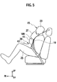
- FIG. 5 is a side view of a state where the upper airbag and the lower airbag according to the first embodiment of the present invention are deployed.
- FIG. 6 is schematic views explaining a tensile force acting on the upper airbag according to the first embodiment of the present invention.
- FIG. 6( a ) shows a pressurized state inside the upper airbag when a fluid is supplied into the inside of the upper airbag.
- FIG. 6( b ) shows a tensile force acting upon the first movement restraining portion due to the pressures inside the upper airbag which are shown in FIG. 6( a ).
- FIG. 7 is a front view of an upper airbag according to a second embodiment of the present invention, which is yet to be deployed and provided with a second movement restraining portion.
- FIG. 8 is a front view showing an upper airbag according to a third embodiment of the present invention, which is yet to be deployed.
- FIG. 9 is a side view of a state where the upper airbag shown in FIG. 8 and a lower airbag are deployed.
- FIG. 10 is side views showing operations of vehicle occupant restraint systems according to the first to third embodiments of the present invention
- FIGS. 10( a ), ( b ) and ( c ) show an initial stage immediately following detection or prediction of a vehicle collision, an intermediate stage following the initial stage, and a late stage, where a lower airbag bends, following the intermediate stage, respectively.
- a vehicle occupant restraint system according to a first embodiment of the present invention will be described with reference to FIG. 1 .
- the upper airbag and the lower airbag are deployed when a vehicle collision detection/prediction system “detects” or “predicts” a collision of the vehicle.
- the “detection” or “prediction” is not limited to a case where a collision load inputted to the vehicle is detected, but broadly includes, for example, such cases as where a running speed decrease of the vehicle is detected, where a situation that the vehicle is expected to come into contact with an obstacle is detected, and where a collision with an obstacle is predicted by external environment detection means formed by an ultrasonic sensor, a laser radar, a camera or the like.
- a seatbelt device 22 in this embodiment is a three-point seatbelt device, and restraints a vehicle occupant 15 by using three points as supporting points, the three points being: a shoulder anchor portion 7 arranged in an upper position in the right side (the outer side in a width direction of the vehicle) of the vehicle occupant 15 ; an unillustrated lap anchor portion arranged in a lower position in the right side (the outer side in the vehicle width direction) of the vehicle occupant 15 ; and an unillustrated buckle anchor portion arranged in a lower position in the left side (the inner side in the vehicle width direction) of the vehicle occupant 15 .
- These shoulder anchor portion 7 , lap anchor portion and buckle anchor portion may be fixed to a vehicle body, or may be fixed to a vehicle seat 6 .
- the seatbelt device 22 is provided with a shoulder belt portion 11 and a lap belt portion 13 .
- the shoulder belt portion 11 is provided to obliquely extend from the anchor portion 7 to a buckle portion 9 , and restrains a part of the vehicle occupant 15 from a right shoulder 17 to a chest 19 .
- the lap belt portion 13 is provided to extend from the lap anchor portion to the buckle portion 9 , and restrains a waist 21 of the vehicle occupant 15 .
- reference numerals 23 and 25 indicate a head and a femoral region of the vehicle occupant 15 , respectively.
- FIG. 2 is a perspective view showing a state where the upper airbag and the lower airbag according to the first embodiment of the present invention have been deployed.
- a command signal is transmitted from the vehicle collision detection/prediction system to an inflator via an airbag control module, and the inflator supplies a pressurized gas to the upper airbag 27 and the lower airbag 29 .
- the upper airbag 27 and the lower airbag 29 are deployed forward of the shoulder belt portion 11 and the lap belt portion 13 , respectively. That is, although being stored inside the shoulder belt portion 11 at normal times (when a collision of the vehicle has not yet been detected or predicted), the upper airbag 27 is deployed forward in the vehicle front-rear direction from the shoulder belt portion 11 when a collision of the vehicle is detected or predicted.
- the upper airbag 27 positions itself, in a deployed/inflated state, in front of the shoulder belt portion 11 and in front of the chest 19 of the vehicle occupant 15 with a part of the upper airbag 27 being connected to the shoulder belt portion 11 .
- the lower airbag 29 is deployed forward in the vehicle front-rear direction from the lap belt portion 13 when a collision of the vehicle is detected or predicted.
- the lower airbag 29 positions itself, in a deployed/inflated state, in front of the lap belt portion 13 and in front of an abdomen of the vehicle occupant 15 with a part of the lower airbag 29 being connected to the lap belt portion 13 .
- the deployed upper airbag 27 and the deployed lower airbag 29 vertically come into contact with each other. That is, the deployed upper airbag 27 is positioned upward of the lower airbag 29 , and has a lower part thereof making direct contact with an upper part of the lower airbag 29 .
- an inertial force forcing the vehicle occupant 15 to move forward in the vehicle front-rear direction relative to a vehicle body (the seat 6 ) acts on the vehicle occupant 15 .
- an upper body of the vehicle occupant 15 turns forward about the neighborhood of the waist 21 restrained by the lap belt portion 13 , and a shoulder 17 of the shoulders 17 , which is located in the buckle portion 9 side where the shoulder 17 is not restrained by the shoulder belt portion 11 , moves forward and downward of the vehicle due to the inertial force.
- FIG. 3 is a front view of the upper airbag according to the first embodiment of the present invention, which is yet to be deployed and is provided with a first movement restraining portion.
- the upper airbag 27 is formed into a bag by sewing together marginal portions 95 of two sheet materials along a sewing line 97 substantially rectangular in a plan view, and has a pressurized gas inflow port 99 provided to a bottom end portion thereof.
- a concaved section 103 (a concave portion 101 ) is formed where the sewing line 97 is formed into a substantially V-shaped curve curved inward (toward the upper right side in FIG. 3 ) with respect to the upper airbag 27 in a plan view.
- the first movement restraining portion 109 linearly joining end portions 105 and 107 which are both ends of the concaved section 103 in the vehicle width direction. That is, in the concaved section 103 , the deployed upper airbag 27 has an outer surface having a shape concaved inwardly.
- the end portion 105 is, out of the end portions of the concaved section 103 having the outer surface concaved inwardly, an end portion in one side corresponding to where the anchor portion 7 of the shoulder belt portion 11 is arranged (that is, out of the left and right shoulders 17 of the vehicle occupant 15 , the side corresponding to a shoulder restrained by the shoulder belt portion 11 ).
- the end portion 107 is, out of the end portions of the concaved section 13 , an end portion in one side corresponding to where the buckle portion 9 of the shoulder belt portion 11 is arranged (that is, out of the left and right shoulders 17 of the vehicle occupant 15 , the side corresponding to a shoulder unrestrained by the shoulder belt portion 11 ).
- the first movement restraining portion 109 specifically is a substantially triangular remainder of at least any one of the two sheet materials when the sheet materials are cut.
- the front-side sheet material is cut out, and a part of the back-side sheet material is kept remaining in a substantially triangle shape.
- the first movement restraining portion 109 is provided so as to, in a lower side of the deployed upper airbag 27 , linearly join the end portion in one side corresponding to where the anchor portion 7 (refer to FIG. 1 ) is arranged and the end portion in the other side corresponding to where the buckle portion 9 (refer to FIG. 1 ) is arranged.
- the upper airbag 27 is thus integrally formed of: an upper airbag main body portion 93 ; and the first movement restraining portion 109 provided along the vehicle width direction to a lower side portion of the upper airbag main body portion 93 . Note that, when a pressurized fluid is supplied into the inside of the upper airbag main body portion 93 through the inflow port 99 , the upper airbag main body portion 93 inflates and is deployed.
- the lower airbag 29 is formed, as shown in FIG. 4 , by lapping a front-side sheet material 31 over a back-side sheet material 33 , and joining marginal portions 35 of these sheet materials to each other through sewing or the like.
- a pair of left and right round discharging holes 45 are formed in an upper portion of the front-side sheet material 31 .
- a part of an inner face of the front-side sheet material 31 and a part of an inner face of the back-side sheet material 33 are joined to each other in a front-rear direction by means of an deployment regulating member 37 formed into a sheet.
- the deployment regulating member 37 is thus arranged inside the lower airbag 29 , and sections in the front-side sheet material 31 and the back-side sheet material 33 are pulled inward with respect to the lower airbag 29 and in a direction substantially parallel to the front-rear direction, the sections having the deployment regulating member 37 fixed thereto. Consequently, in the front-rear direction, a thickness of the lower airbag 29 at a portion where the deployment regulating member 37 is fixed is smaller than those of the other portions, and a hollow 39 is formed on an outer surface of the lower airbag 29 .
- the deployment regulating member 37 thus regulates deployment of the lower airbag 29 in the front-rear direction when the lower airbag 29 is deployed.
- a section in the lower airbag 29 which is upper than the deployment regulating member 37 will be referred to as an upper section 41
- a section in the lower airbag 29 which is lower than the deployment regulating member 37 will be referred to as a lower section 43 .
- a thickness of the lower airbag 29 at the portion where the deployment regulating member 37 is fixed is smaller than those of the other portions. Consequently, the deployed lower airbag 29 becomes more likely to bend about the portion where the deployment regulating member 37 is fixed, and the upper section 41 becomes moveable in a front-rear direction relatively freely as compared to the lower section 43 .
- FIG. 5 is a side view of a state where the upper airbag and the lower airbag according to the first embodiment of the present invention are deployed.
- the first movement restraining portion 109 When the upper airbag 27 including the first movement restraining portion 109 and the lower airbag 29 are deployed, the first movement restraining portion 109 extends downward from the lower side of the upper airbag 27 , and is positioned, with respect to the vehicle, in the rear of the upper section 41 of the deployed lower airbag 29 (that is, between the upper section 41 of the lower airbag 29 and the vehicle occupant 15 ), as shown in FIG. 5 .
- the first movement restraining portion 109 serves as a non-deploying portion in the upper airbag 27 .
- FIG. 6 is schematic views explaining a tensile force acting on the upper airbag according to the first embodiment of the present invention.
- FIG. 6( a ) shows a pressurized state inside the upper airbag when a fluid is flown into the inside of the upper airbag
- FIG. 6( b ) shows a tensile force acting on the first movement restraining portion due to the pressures inside the upper airbag.
- a supply pipe 111 connected to the inflator is fit to the inflow port 99 formed in the bottom end portion of the upper airbag 27 .
- the upper airbag 27 is deployed when a pressurized fluid is supplied from the inflator into the inside of the upper airbag 27 via the supply pipe 111 .
- a pressure P uniformly acts on each of sections in the inner surface of the deployed upper airbag 27 .
- the concaved section 103 (the concave portion 101 ) is provided in the upper airbag 27 where the upper airbag 27 has an outer surface concaved inwardly when deployed.
- the pressure P acts on the concaved section 103 in a manner pushing the concaved section 103 in an outward direction with respect the upper airbag 27 , whereby the end portions 105 and 107 of the concaved section 103 are forced to be more distant from each other.
- a tensile force T along an arrow in FIG. 6( b ) acts on the first movement restraining portion 109 .
- the first movement restraining portion 109 is provided which extends downward from the lower side of the deployed upper airbag 27 , is positioned in the rear, in the vehicle front-rear direction, of the deployed lower airbag 29 , and, when the deployed upper airbag 27 and the deployed lower airbag 29 comes into contact with each other, restrains relative movement between the airbags 27 and 29 in the front-rear direction.
- the head 23 of the vehicle occupant 15 can be more quickly restrained in a manner allowing the head 23 of the vehicle occupant 15 bending forward to be received by the upper and lower airbags 27 and 29 , and thereby allowing a load thereof to be supported by the femoral regions 25 of the vehicle occupant 15 or a seating face of a seat cushion 3 through the upper and lower airbags 27 and 29 .
- the shoulder belt portion 11 is provided to extend, from the anchor portion arranged in one of the left and right sides of the sitting vehicle occupant 15 near the level of the corresponding left and right shoulders 17 thereof, to the buckle portion 9 arranged in the other side, and the first movement restraining portion 109 is provided to, in the lower side of the deployed upper airbag 27 , join the end portion in the side corresponding to where the anchor portion 7 is arranged and the end portion in the side corresponding to where the buckle portion 9 is arranged.
- the tensile force T occurs on the first movement restraining portion 109 located between the end portion in the side corresponding to where the anchor portion 7 is arranged and the end portion in the side where the buckle portion 9 is arranged.
- the first movement restraining portion 109 made tense by this tensile force T, intrusion of the upper section 41 of the lower airbag 29 into the rear of the upper airbag 27 can be prevented.
- This provides a reliable guide for the upper section 41 of the lower airbag 29 by which the lower airbag 29 is securely bent and the upper section 41 thereof securely falls forward in the vehicle front-rear direction.
- the tensile force T is applied on the first movement restraining portion 109 of the upper airbag 27 .
- the upper airbag 27 is prevented from moving forward relative to the lower airbag 29 , whereby relative positions of the upper airbag 27 and the lower airbag 29 in the front-rear direction can be maintained properly.
- the concave portion 101 where the upper airbag 27 has the outer surface concaved inwardly when deployed is provided in the above upper airbag 27 , and the first movement restraining portion 109 joins the end portions 105 and 107 of the concave portion 101 in the vehicle width direction.
- the first movement restraining portion 109 is provided as a non-deploying portion in the upper airbag 27 . Consequently, when the upper airbag 27 and the lower airbag 29 are deployed, the lower airbag 29 and the first movement restraining portion 109 of the upper airbag 27 are positioned in a state overlapping each other in the vehicle front-rear direction. On the other hand, if the first movement restraining portion 109 is provided as a deploying portion, the lower airbag 29 and the first movement restraining portion 109 of the upper airbag 27 are deployed at the same time in a overlapping region, which leads to a risk that an excessive force of deployment may be applied to the vehicle occupant 15 . Consequently, by setting a non-deploying portion in the upper airbag 27 as the first movement restraining portion 109 , a force of deployment applied on the vehicle occupant 15 can be controlled.
- the upper airbag 27 is formed by joining together the marginal portions 95 of the two sheet materials;
- the concave portion 101 is the concaved section 103 obtained by arranging the joined portions inward with respect to the upper airbag 27 ;
- the first movement restraining portion 109 is formed of a part of the sheet materials which is arranged in the concaved section 103 .
- first movement restraining portion 109 production work of the first movement restraining portion 109 can be made simple since the first movement restraining portion 109 can be produced only by having a part of the marginal portions 95 not cut out, but left as it is.
- FIG. 7 is a front view of an upper airbag according to the second embodiment of the present invention, which is provided with a second movement restraining portion.
- This upper airbag 113 is formed of an upper airbag main body portion 115 , and the second movement restraining portion 117 which is a linear member joining the end portions 105 and 107 of the concaved section 103 of the upper airbag main body portion 115 .
- the second movement restraining portion 117 any one of various linear members can be applied as long as the one is an inelastic string, strip, and the like. Additionally, both ends of the second movement restraining portion 117 can be fixed to the upper airbag main body portion 115 through sewing or the like.
- the second movement restraining portion 117 is formed of a linear member, whereby a length of the second movement restraining portion 117 can be easily changed.
- FIG. 8 is a front view showing an upper airbag according to a third embodiment of the present invention, which is yet to be deployed
- FIG. 9 is a side view of a state where the upper airbag shown in FIG. 8 and a lower airbag are deployed.
- the upper airbag 119 is integrally formed of: an upper airbag main body portion 121 ; the first movement restraining portion 109 provided to a lower side of the upper airbag main body portion 121 ; and an extended portion 123 provided on top of the upper airbag main body portion 121 .
- the extended portion 123 is a substantially trapezoidal remainder of at least any one of two front-side and back-side sheet materials forming the upper airbag main body portion 121 when the sheet materials are cut.
- an insertion hole 125 is formed through which the shoulder belt portion 11 (webbing) is inserted.
- the insertion hole 125 is formed into a size which allows the upper airbag 119 to move with respect to the shoulder belt portion 11 with the shoulder belt portion 11 being inserted therethrough.
- an upper end of the deployed upper airbag 119 is movably supported by the shoulder belt portion 11 .
- the upper end of the deployed upper airbag 119 is movably supported by the shoulder belt portion 11 . Consequently, as shown in FIG. 9 , when the upper airbag 119 and the lower airbag 29 are deployed, an upper portion of the upper airbag main body portion 121 , which is forced by the deployment to be more distant from the vehicle occupant 15 , is pulled rearward (toward the vehicle occupant 15 ) in an arrowed direction by the extended portion 123 through which the shoulder belt portion 11 (webbing) is inserted (the closeness between the upper airbag 27 and the shoulder belt portion 11 is maintained). Thereby, the upper airbag 119 is prevented from moving forward and thereby moving apart from the chest 19 of the vehicle occupant 15 .
- FIG. 10 is side views showing the operations of vehicle occupant restraint systems according to the first to third embodiments of the present invention
- FIGS. 10( a ), ( b ) and ( c ) show an initial stage immediately following detection or prediction of a vehicle collision, an intermediate stage following the initial stage, and a late stage, where the lower airbag bends, following the intermediate stage, respectively.
- the upper airbag 27 is deployed forward in the vehicle front-rear direction from the shoulder belt portion 11
- the lower airbag 29 is deployed forward in the vehicle front-rear direction from the lap belt portion 13 .
- the lower airbag 29 is deployed upward from the lap belt portion 13 also, whereby an upper face of the lower airbag 29 makes a direct contact with a lower face of the upper airbag 27 .
- the discharging holes 45 are formed in a front face of the lower airbag 29 , a pressurized fluid (for example, a pressurized gas) inside the lower airbag 29 is discharged forward in the vehicle front-rear direction from these discharging holes 45 .
- the deployment regulating member 37 is arranged in the lower airbag 29 , the upper section 41 thereof bends about the deployment regulating member 37 with respect to the lower section 43 thereof in a manner falling down forward in the vehicle front-rear direction.
- the fluid 63 is discharged forward so that the discharging holes 45 can be prevented from becoming narrow even when the lower airbag 29 bends.
Abstract
Description
Claims (11)
Applications Claiming Priority (2)
| Application Number | Priority Date | Filing Date | Title |
|---|---|---|---|
| JP2008123406A JP4929230B2 (en) | 2008-05-09 | 2008-05-09 | Crew protection device |
| JP2008-123406 | 2008-05-09 |
Publications (2)
| Publication Number | Publication Date |
|---|---|
| US20090278339A1 US20090278339A1 (en) | 2009-11-12 |
| US7971902B2 true US7971902B2 (en) | 2011-07-05 |
Family
ID=41100493
Family Applications (1)
| Application Number | Title | Priority Date | Filing Date |
|---|---|---|---|
| US12/431,919 Expired - Fee Related US7971902B2 (en) | 2008-05-09 | 2009-04-29 | Vehicle occupant restraint system |
Country Status (6)
| Country | Link |
|---|---|
| US (1) | US7971902B2 (en) |
| EP (1) | EP2116429B1 (en) |
| JP (1) | JP4929230B2 (en) |
| KR (1) | KR101051238B1 (en) |
| CN (1) | CN101574950B (en) |
| AT (1) | ATE530393T1 (en) |
Cited By (2)
| Publication number | Priority date | Publication date | Assignee | Title |
|---|---|---|---|---|
| US9616747B1 (en) | 2013-01-29 | 2017-04-11 | Intelligent Technologies International, Inc. | Method for controlling travel of golf carts and all-terrain vehicles |
| US11390232B2 (en) * | 2019-10-31 | 2022-07-19 | ZF Passive Safety Systems US Inc. | Vehicle safety systems including inflatable seatbelt restraint |
Families Citing this family (12)
| Publication number | Priority date | Publication date | Assignee | Title |
|---|---|---|---|---|
| JP4569684B2 (en) * | 2008-08-01 | 2010-10-27 | トヨタ自動車株式会社 | Vehicle occupant restraint system |
| DE102011000052A1 (en) * | 2010-01-08 | 2011-07-28 | TK Holdings, Inc., Mich. | air bag |
| JP5440456B2 (en) * | 2010-09-07 | 2014-03-12 | トヨタ紡織株式会社 | Vehicle seat |
| CN105966341A (en) * | 2016-05-31 | 2016-09-28 | 孙本新 | Safety baffle device in front of seat of passenger car |
| JP6438996B2 (en) * | 2017-03-27 | 2018-12-19 | 株式会社Subaru | Crew protection device |
| DE102017003291A1 (en) | 2017-04-04 | 2018-10-04 | GM Global Technology Operations LLC (n. d. Ges. d. Staates Delaware) | Motor vehicle with seat belt restraint system |
| DE102018123209A1 (en) * | 2018-09-20 | 2020-03-26 | Joyson Safety Systems Germany Gmbh | Seat belt assemblies for a motor vehicle |
| CN109204218B (en) * | 2018-09-28 | 2024-02-27 | 上海东方久乐汽车安全气囊有限公司 | Child seat safety airbag and child seat provided with same |
| JP7243557B2 (en) * | 2018-10-22 | 2023-03-22 | 豊田合成株式会社 | passenger protection device |
| US11548468B2 (en) * | 2019-09-30 | 2023-01-10 | Toyoda Gosei Co., Ltd. | Occupant protection system |
| JP7276224B2 (en) * | 2020-03-31 | 2023-05-18 | 豊田合成株式会社 | passenger protection device |
| US11648905B2 (en) * | 2020-08-11 | 2023-05-16 | Toyoda Gosei Co., Ltd. | Occupant protection device |
Citations (16)
| Publication number | Priority date | Publication date | Assignee | Title |
|---|---|---|---|---|
| US3801156A (en) * | 1971-11-15 | 1974-04-02 | H Granig | Safety-belt |
| US3841654A (en) * | 1972-09-21 | 1974-10-15 | Allied Chem | Vehicle safety system |
| US3865398A (en) * | 1973-02-05 | 1975-02-11 | Toni Woll | Expandable crash-restraining means |
| US3866940A (en) * | 1973-01-11 | 1975-02-18 | Allied Chem | Differentially inflatable restraining band for vehicles |
| US3905615A (en) | 1974-06-27 | 1975-09-16 | Us Navy | Inflatable body and head restraint |
| US6142511A (en) * | 1995-12-22 | 2000-11-07 | Universal Propulsion Company | Inflatable passenger restraint and inflator therefor |
| KR100276975B1 (en) | 1998-02-10 | 2001-01-15 | 윤장진 | Collision detector for airbag system and method |
| US20060028004A1 (en) * | 2004-08-09 | 2006-02-09 | Nissan Motor Co., Ltd. | Vehicle occupant restraint system and method |
| EP1669253A2 (en) | 2004-12-07 | 2006-06-14 | Nissan Motor Co., Ltd. | Vehicle occupant restraint system and method |
| US20060208471A1 (en) * | 2005-02-02 | 2006-09-21 | Ford Global Technologies, Llc | Inflatable seatbelt system |
| US20060255573A1 (en) * | 2005-04-18 | 2006-11-16 | Hideo Tobata | Passenger protective device and method |
| US20070029767A1 (en) * | 2005-08-02 | 2007-02-08 | Takata Corporation | Air belt and air belt apparatus |
| US20070102910A1 (en) * | 2005-11-10 | 2007-05-10 | Takata Corporation | Air belt apparatus |
| US7413220B2 (en) * | 2004-02-27 | 2008-08-19 | Takata Corporation | Vehicle occupant protection system and inflator |
| US7665761B1 (en) * | 2008-03-27 | 2010-02-23 | Amsafe, Inc. | Inflatable personal restraint systems and associated methods of use and manufacture |
| US7669891B2 (en) * | 2008-05-09 | 2010-03-02 | Nissan Motor Co., Ltd. | Vehicle occupant protection system |
Family Cites Families (5)
| Publication number | Priority date | Publication date | Assignee | Title |
|---|---|---|---|---|
| US6378898B1 (en) | 1999-06-09 | 2002-04-30 | The B.F. Goodrich Company | Inflatable air bag for an inflatable restraint system |
| JP4310115B2 (en) * | 2002-03-06 | 2009-08-05 | 本田技研工業株式会社 | Scooter type motorcycle with airbag device |
| JP2005096653A (en) * | 2003-09-25 | 2005-04-14 | Toyoda Gosei Co Ltd | Air bag for rear seat, and air bag device for rear seat |
| JP4453480B2 (en) | 2004-08-09 | 2010-04-21 | 日産自動車株式会社 | Occupant protection device and occupant protection method |
| JP4595455B2 (en) * | 2004-09-09 | 2010-12-08 | 日産自動車株式会社 | Occupant protection device and occupant protection method |
-
2008
- 2008-05-09 JP JP2008123406A patent/JP4929230B2/en not_active Expired - Fee Related
-
2009
- 2009-04-28 CN CN2009101353993A patent/CN101574950B/en not_active Expired - Fee Related
- 2009-04-29 EP EP09158998A patent/EP2116429B1/en not_active Not-in-force
- 2009-04-29 US US12/431,919 patent/US7971902B2/en not_active Expired - Fee Related
- 2009-04-29 AT AT09158998T patent/ATE530393T1/en not_active IP Right Cessation
- 2009-05-08 KR KR1020090040174A patent/KR101051238B1/en active IP Right Grant
Patent Citations (21)
| Publication number | Priority date | Publication date | Assignee | Title |
|---|---|---|---|---|
| US3801156A (en) * | 1971-11-15 | 1974-04-02 | H Granig | Safety-belt |
| US3841654A (en) * | 1972-09-21 | 1974-10-15 | Allied Chem | Vehicle safety system |
| US3866940A (en) * | 1973-01-11 | 1975-02-18 | Allied Chem | Differentially inflatable restraining band for vehicles |
| US3865398A (en) * | 1973-02-05 | 1975-02-11 | Toni Woll | Expandable crash-restraining means |
| US3905615A (en) | 1974-06-27 | 1975-09-16 | Us Navy | Inflatable body and head restraint |
| US6142511A (en) * | 1995-12-22 | 2000-11-07 | Universal Propulsion Company | Inflatable passenger restraint and inflator therefor |
| KR100276975B1 (en) | 1998-02-10 | 2001-01-15 | 윤장진 | Collision detector for airbag system and method |
| US7413220B2 (en) * | 2004-02-27 | 2008-08-19 | Takata Corporation | Vehicle occupant protection system and inflator |
| US20060028004A1 (en) * | 2004-08-09 | 2006-02-09 | Nissan Motor Co., Ltd. | Vehicle occupant restraint system and method |
| EP1625980A2 (en) | 2004-08-09 | 2006-02-15 | Nissan Motor Co., Ltd. | Vehicle occupant restraint system and method |
| US7513524B2 (en) * | 2004-08-09 | 2009-04-07 | Nissan Motor Co., Ltd. | Vehicle occupant restraint system and method |
| JP2006160062A (en) | 2004-12-07 | 2006-06-22 | Nissan Motor Co Ltd | Occupant protection device and occupant protection method |
| US7163236B2 (en) * | 2004-12-07 | 2007-01-16 | Nissan Motor Co., Ltd. | Vehicle occupant restraint system and vehicle occupant restraint method |
| EP1669253A2 (en) | 2004-12-07 | 2006-06-14 | Nissan Motor Co., Ltd. | Vehicle occupant restraint system and method |
| US20060208471A1 (en) * | 2005-02-02 | 2006-09-21 | Ford Global Technologies, Llc | Inflatable seatbelt system |
| US20060255573A1 (en) * | 2005-04-18 | 2006-11-16 | Hideo Tobata | Passenger protective device and method |
| US7600780B2 (en) * | 2005-04-18 | 2009-10-13 | Nissan Motor Co., Ltd. | Passenger protective device and method |
| US20070029767A1 (en) * | 2005-08-02 | 2007-02-08 | Takata Corporation | Air belt and air belt apparatus |
| US20070102910A1 (en) * | 2005-11-10 | 2007-05-10 | Takata Corporation | Air belt apparatus |
| US7665761B1 (en) * | 2008-03-27 | 2010-02-23 | Amsafe, Inc. | Inflatable personal restraint systems and associated methods of use and manufacture |
| US7669891B2 (en) * | 2008-05-09 | 2010-03-02 | Nissan Motor Co., Ltd. | Vehicle occupant protection system |
Cited By (2)
| Publication number | Priority date | Publication date | Assignee | Title |
|---|---|---|---|---|
| US9616747B1 (en) | 2013-01-29 | 2017-04-11 | Intelligent Technologies International, Inc. | Method for controlling travel of golf carts and all-terrain vehicles |
| US11390232B2 (en) * | 2019-10-31 | 2022-07-19 | ZF Passive Safety Systems US Inc. | Vehicle safety systems including inflatable seatbelt restraint |
Also Published As
| Publication number | Publication date |
|---|---|
| ATE530393T1 (en) | 2011-11-15 |
| EP2116429B1 (en) | 2011-10-26 |
| JP2009269539A (en) | 2009-11-19 |
| KR20090117655A (en) | 2009-11-12 |
| CN101574950A (en) | 2009-11-11 |
| JP4929230B2 (en) | 2012-05-09 |
| US20090278339A1 (en) | 2009-11-12 |
| KR101051238B1 (en) | 2011-07-21 |
| CN101574950B (en) | 2012-03-14 |
| EP2116429A1 (en) | 2009-11-11 |
Similar Documents
| Publication | Publication Date | Title |
|---|---|---|
| US7971902B2 (en) | Vehicle occupant restraint system | |
| US8104790B2 (en) | Vehicular occupant restraint system | |
| JP5081716B2 (en) | Crew protection device | |
| US20140015234A1 (en) | Seat cushion airbag device | |
| US11524648B2 (en) | Occupant protection system | |
| JP2010058544A (en) | Front passenger seat airbag apparatus | |
| JP2009196551A (en) | Airbag device for vehicle | |
| JP2010083384A (en) | Occupant restraint system | |
| US8573633B2 (en) | Seat cushion airbag apparatus | |
| JP7001914B2 (en) | Vehicle seat | |
| EP1688323A1 (en) | Occupant protection device | |
| KR20220038795A (en) | Airbag device, vehicle seat, and method of ignition of the airbag device | |
| JPWO2006003749A1 (en) | Lumbar restraint airbag device and seat cushion device using the same | |
| JP2006290258A (en) | Occupant restraining device | |
| EP3696028B1 (en) | Occupant restraint system | |
| JP2010042719A (en) | Seat back structure | |
| JP2010105544A (en) | Occupant restraint device | |
| JP4687300B2 (en) | Crew restraint system | |
| JP2010143422A (en) | Lateral-collision head restraining device | |
| JP2006290259A (en) | Seat belt device | |
| JP2010047223A (en) | Occupant protection device | |
| JP4946444B2 (en) | Crew protection device | |
| JP7032196B2 (en) | Crew restraint device | |
| JP2018030555A (en) | Vehicular occupant protection device | |
| JP5871475B2 (en) | Crew protection device |
Legal Events
| Date | Code | Title | Description |
|---|---|---|---|
| AS | Assignment |
Owner name: TAKATA CORPORATION, JAPAN Free format text: ASSIGNMENT OF ASSIGNORS INTEREST;ASSIGNORS:AZUMA, SEIJI;OOTA, KOUICHI;OKAMOTO, HIDEAKI;REEL/FRAME:022611/0936;SIGNING DATES FROM 20090303 TO 20090304 Owner name: NISSAN MOTOR CO., LTD., JAPAN Free format text: ASSIGNMENT OF ASSIGNORS INTEREST;ASSIGNORS:AZUMA, SEIJI;OOTA, KOUICHI;OKAMOTO, HIDEAKI;REEL/FRAME:022611/0936;SIGNING DATES FROM 20090303 TO 20090304 Owner name: TAKATA CORPORATION, JAPAN Free format text: ASSIGNMENT OF ASSIGNORS INTEREST;ASSIGNORS:AZUMA, SEIJI;OOTA, KOUICHI;OKAMOTO, HIDEAKI;SIGNING DATES FROM 20090303 TO 20090304;REEL/FRAME:022611/0936 Owner name: NISSAN MOTOR CO., LTD., JAPAN Free format text: ASSIGNMENT OF ASSIGNORS INTEREST;ASSIGNORS:AZUMA, SEIJI;OOTA, KOUICHI;OKAMOTO, HIDEAKI;SIGNING DATES FROM 20090303 TO 20090304;REEL/FRAME:022611/0936 |
|
| FEPP | Fee payment procedure |
Free format text: PAYOR NUMBER ASSIGNED (ORIGINAL EVENT CODE: ASPN); ENTITY STATUS OF PATENT OWNER: LARGE ENTITY |
|
| STCF | Information on status: patent grant |
Free format text: PATENTED CASE |
|
| FPAY | Fee payment |
Year of fee payment: 4 |
|
| AS | Assignment |
Owner name: JOYSON SAFETY SYSTEMS JAPAN K.K., JAPAN Free format text: ASSIGNMENT OF ASSIGNORS INTEREST;ASSIGNOR:TAKATA CORPORATION;REEL/FRAME:045938/0931 Effective date: 20180410 |
|
| MAFP | Maintenance fee payment |
Free format text: PAYMENT OF MAINTENANCE FEE, 8TH YEAR, LARGE ENTITY (ORIGINAL EVENT CODE: M1552); ENTITY STATUS OF PATENT OWNER: LARGE ENTITY Year of fee payment: 8 |
|
| FEPP | Fee payment procedure |
Free format text: MAINTENANCE FEE REMINDER MAILED (ORIGINAL EVENT CODE: REM.); ENTITY STATUS OF PATENT OWNER: LARGE ENTITY |
|
| LAPS | Lapse for failure to pay maintenance fees |
Free format text: PATENT EXPIRED FOR FAILURE TO PAY MAINTENANCE FEES (ORIGINAL EVENT CODE: EXP.); ENTITY STATUS OF PATENT OWNER: LARGE ENTITY |
|
| STCH | Information on status: patent discontinuation |
Free format text: PATENT EXPIRED DUE TO NONPAYMENT OF MAINTENANCE FEES UNDER 37 CFR 1.362 |
|
| FP | Lapsed due to failure to pay maintenance fee |
Effective date: 20230705 |