US7972575B2 - Two-phase pipette - Google Patents
Two-phase pipette Download PDFInfo
- Publication number
- US7972575B2 US7972575B2 US11/919,879 US91987906A US7972575B2 US 7972575 B2 US7972575 B2 US 7972575B2 US 91987906 A US91987906 A US 91987906A US 7972575 B2 US7972575 B2 US 7972575B2
- Authority
- US
- United States
- Prior art keywords
- piston
- cylinder
- pipette
- liquid
- volume
- Prior art date
- Legal status (The legal status is an assumption and is not a legal conclusion. Google has not performed a legal analysis and makes no representation as to the accuracy of the status listed.)
- Active, expires
Links
Images


Classifications
-
- B—PERFORMING OPERATIONS; TRANSPORTING
- B01—PHYSICAL OR CHEMICAL PROCESSES OR APPARATUS IN GENERAL
- B01L—CHEMICAL OR PHYSICAL LABORATORY APPARATUS FOR GENERAL USE
- B01L3/00—Containers or dishes for laboratory use, e.g. laboratory glassware; Droppers
- B01L3/02—Burettes; Pipettes
- B01L3/021—Pipettes, i.e. with only one conduit for withdrawing and redistributing liquids
- B01L3/0217—Pipettes, i.e. with only one conduit for withdrawing and redistributing liquids of the plunger pump type
- B01L3/0227—Details of motor drive means
-
- B—PERFORMING OPERATIONS; TRANSPORTING
- B01—PHYSICAL OR CHEMICAL PROCESSES OR APPARATUS IN GENERAL
- B01L—CHEMICAL OR PHYSICAL LABORATORY APPARATUS FOR GENERAL USE
- B01L3/00—Containers or dishes for laboratory use, e.g. laboratory glassware; Droppers
- B01L3/02—Burettes; Pipettes
- B01L3/021—Pipettes, i.e. with only one conduit for withdrawing and redistributing liquids
- B01L3/0217—Pipettes, i.e. with only one conduit for withdrawing and redistributing liquids of the plunger pump type
- B01L3/0237—Details of electronic control, e.g. relating to user interface
-
- B—PERFORMING OPERATIONS; TRANSPORTING
- B01—PHYSICAL OR CHEMICAL PROCESSES OR APPARATUS IN GENERAL
- B01L—CHEMICAL OR PHYSICAL LABORATORY APPARATUS FOR GENERAL USE
- B01L2200/00—Solutions for specific problems relating to chemical or physical laboratory apparatus
- B01L2200/06—Fluid handling related problems
- B01L2200/0605—Metering of fluids
-
- B—PERFORMING OPERATIONS; TRANSPORTING
- B01—PHYSICAL OR CHEMICAL PROCESSES OR APPARATUS IN GENERAL
- B01L—CHEMICAL OR PHYSICAL LABORATORY APPARATUS FOR GENERAL USE
- B01L2200/00—Solutions for specific problems relating to chemical or physical laboratory apparatus
- B01L2200/08—Ergonomic or safety aspects of handling devices
- B01L2200/087—Ergonomic aspects
-
- B—PERFORMING OPERATIONS; TRANSPORTING
- B01—PHYSICAL OR CHEMICAL PROCESSES OR APPARATUS IN GENERAL
- B01L—CHEMICAL OR PHYSICAL LABORATORY APPARATUS FOR GENERAL USE
- B01L2200/00—Solutions for specific problems relating to chemical or physical laboratory apparatus
- B01L2200/14—Process control and prevention of errors
- B01L2200/148—Specific details about calibrations
-
- B—PERFORMING OPERATIONS; TRANSPORTING
- B01—PHYSICAL OR CHEMICAL PROCESSES OR APPARATUS IN GENERAL
- B01L—CHEMICAL OR PHYSICAL LABORATORY APPARATUS FOR GENERAL USE
- B01L2400/00—Moving or stopping fluids
- B01L2400/04—Moving fluids with specific forces or mechanical means
- B01L2400/0475—Moving fluids with specific forces or mechanical means specific mechanical means and fluid pressure
- B01L2400/0487—Moving fluids with specific forces or mechanical means specific mechanical means and fluid pressure fluid pressure, pneumatics
-
- B—PERFORMING OPERATIONS; TRANSPORTING
- B01—PHYSICAL OR CHEMICAL PROCESSES OR APPARATUS IN GENERAL
- B01L—CHEMICAL OR PHYSICAL LABORATORY APPARATUS FOR GENERAL USE
- B01L3/00—Containers or dishes for laboratory use, e.g. laboratory glassware; Droppers
- B01L3/02—Burettes; Pipettes
- B01L3/021—Pipettes, i.e. with only one conduit for withdrawing and redistributing liquids
- B01L3/0217—Pipettes, i.e. with only one conduit for withdrawing and redistributing liquids of the plunger pump type
- B01L3/0224—Pipettes, i.e. with only one conduit for withdrawing and redistributing liquids of the plunger pump type having mechanical means to set stroke length, e.g. movable stops
-
- B—PERFORMING OPERATIONS; TRANSPORTING
- B01—PHYSICAL OR CHEMICAL PROCESSES OR APPARATUS IN GENERAL
- B01L—CHEMICAL OR PHYSICAL LABORATORY APPARATUS FOR GENERAL USE
- B01L3/00—Containers or dishes for laboratory use, e.g. laboratory glassware; Droppers
- B01L3/02—Burettes; Pipettes
- B01L3/021—Pipettes, i.e. with only one conduit for withdrawing and redistributing liquids
- B01L3/0217—Pipettes, i.e. with only one conduit for withdrawing and redistributing liquids of the plunger pump type
- B01L3/0234—Repeating pipettes, i.e. for dispensing multiple doses from a single charge
Definitions
- the invention relates to a pipette for use for liquid dosage comprising a motor-operated piston.
- the invention relates specifically to the operation of the movement of the piston.
- Pipettes are used for liquid dosage in laboratories, the pipettes comprising a piston movable in a cylinder by means of an electric motor, by which piston liquid is aspirated in accordance with selected pipette function into and out of a tip connected to the cylinder.
- the liquid volume is usually adjustable.
- Pipettes comprise a control system and its user interface for i.a. setting of the volume and other necessary adjustments and for giving commands for performing operations.
- the user interface has the necessary push buttons for this purpose.
- the user interface also has a display by means of which i.a. the volume and other necessary data can be displayed.
- the display can also show menus by means of which the functions can be selected and settings fed using the push buttons.
- the pipetting functions to be used are e.g. direct, reverse and step pipetting.
- Direct pipetting involves aspiration of a desired volume into the pipette and discharge of the volume.
- Reverse pipetting function involves aspiration of a volume greater than the one desired into the pipette, with the desired volume being subsequently discharged.
- Step pipetting involves aspiration of a volume into the pipette, the volume being subsequently discharged in a plurality of minor portions.
- the piston has a basic position from which it can be moved upwards to an upper position. The distance between these positions defines the dosable volume.
- the piston has a lower position to which the piston can be moved downwards from the basic position by the length a so-called secondary movement.
- direct pipetting the piston is moved from the basic position to the upper position when aspirating liquid and from the upper position to the lower position when discharging liquid.
- the secondary movement thus ensures that the liquid is discharged as completely as possible.
- reverse pipetting the piston is moved from the lower position to the upper position when aspiring the liquid and from the upper position to the basic position when discharging the liquid.
- step pipetting the piston is moved from the lower position to the upper position when aspirating the liquid and from the upper position step to the basic position when discharging the liquid.
- step pipetting the excess volume aspirated by the secondary movement specifically ensures that also the last dosage to be discharged is full.
- reverse pipetting and step pipetting the volume corresponding to the secondary movement is usually thrown away after pipetting.
- known electronic pipettes the length of the secondary movement is constant.
- Publication U.S. Pat. No. 3,343,539 discloses a dispensing device corresponding to a manually operated pipette in which also the length of the secondary movement is adjustable.
- Publication FI 44 070 discloses a manually operated pipette in which also the length of the secondary movement is adjustable, specifically the same distance as the primary movement and together and simultaneously with the primary movement.
- the length of the secondary movement is adjustable. The user can thus change it to as optimal as possible for each pipetting function.
- FIG. 1 illustrates a pipette according the invention
- FIG. 2 illustrates a function of the pipette as a chart
- FIG. 3 illustrates how the discharge volume corresponding to the secondary movement of direct pipetting can be changed.
- FIG. 4 illustrates how the excess volume of the step function can be changed.
- the piston is moved by means of a motor.
- the piston has a basic position from which it can be moved upwards to an upper position. The distance between these positions defines the dosable volume.
- the piston has a lower position to which the piston can be moved downwards from the basic position by the length of a so-called secondary movement. The length of this secondary movement is adjustable. The user can thus change it as optimal as possible for each pipetting function.
- the length of the secondary movement can be set suitable depending on the pipetting function in question. This is a benefit for example when dosing into a liquid and when it is desirable that no air gets into the liquid when doing this.
- the discharge can thus be optimized by adjustment so that the tip is just barely emptied and no air gets into the liquid from the tip.
- the extra discharge movement can also be used in reverse and step function, whereby the piston is driven lower than when aspirating liquid. In this way a discharge of the tip as complete as possible is confirmed. It is then actually a three-phase pipette, in which the piston has two lower positions: a lower position for aspiration and below it a lower position for discharge. Also the discharge movement can be made adjustable. According to the invention it is also possible to make a special arrangement in which the lower position for aspiration is constant and the lower position for discharge is adjustable.
- a user interface associated with the control system of the pipette, which interface comprises setting keys, an operation switch and a display.
- the display shows e.g. the volume and possibly other necessary data.
- the display also shows menus allowing data input in the control system by means of the setting keys, the data comprising e.g. selecting the desired pipetting function and the settings used for this.
- the pipette mechanism and the control system may operate on the same principle as e.g. those in Finnpipette® Novus pipette which came into the market in 2004 (manufacturer: Thermo Electron Oy, Finland) or as disclosed in FI 96007 (corresponding to EP 576967).
- FIG. 1 illustrates a pipette operated with an electric motor.
- the user interface of the control system comprises an operating switch 1 , setting keyboard 2 and a display 3 .
- the operating switch 1 has been disposed in a wheel 4 rotatable relative to the body. This allows the user to adjust the position of the operating switch.
- a push-button 6 of the tip removal sleeve 5 is provided in the pipette body on the opposite side of the switch.
- the tip is discharged by manual force. It has preferably been relieved by a lever mechanism, especially by such in which the tip remover is urged to move by means of a wheel relative to the pipette body, as described in FI 92374 (corresponding e.g. to EP 566939).
- the display 3 is disposed at the top of the pipette, in a position upwardly oblique away from the push-button 6 of the tip removal sleeve on the upper surface of a projection.
- a power source is provided within the projection.
- the setting keyboard 2 is disposed on the upper surface of the projection, at its end on the side of the body.
- the display shows necessary information about the settings used each time, such as e.g. the pipette volume and function in use and the current function step.
- the display also shows different menus in each situation, allowing the settings to be changed.
- the pipette settings can be changed by means of the setting keyboard 2 .
- the setting keys are: a right-hand selection key 7 , a left-hand selection key 8 and a bifunctional scanning key (arrow keys) 9 .
- the current is switched on by depression of any key.
- the selection keys allow the user to move forwards or backwards in a menu hierarchy or to start using a selected function.
- the scanning key allows the user to move to an option on the display or to change characters on the display (such as numbers or writing).
- the selection function enables the user to move to the desired location in the menu and to confirm it by means of the selection keys.
- the change function scans a character string, of which the desired character is selected.
- the characters may act on a setting of the function (e.g. volume, piston stroke speed), or they may be confined to giving information.
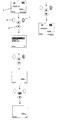
- FIG. 2 is a schematic view of the pipette functions.
- the core of the control system is a central processing unit (CPU) 10 connected with a memory 11 .
- the CPU is used by means of the function keys, i.e. the operating switch 1 and the setting keyboard 2 .
- the CPU is informed of the piston position by a position sensor 12 .
- the CPU gives the commands needed for actuating the piston to a driver 13 , which controls a step motor 14 .
- the functions are indicated on the display (liquid crystal display LCD) 3 . Some functions are indicated with acoustic signals by means of a buzzer 15 .
- the CPU is connected to a serial interface 16 allowing data input into or output from the CPU.
- a chargeable 3.7 V Li ion battery 17 acts as the voltage source.
- the battery comprises a voltage control and reactivating circuit 18 .
- the battery is charged over terminals 19 using a charger 20 in a stand 21 .
- the charging is also controlled by the CPU.
- FIG. 3 exemplifies how to change the volume of the secondary movement in direct pipetting.
- the PIPETTE function direct pipetting
- the piston is driven from the basic position to the upper position defined by the set volume and when discharging the liquid to the lower position below the basic position by a length of a so-called secondary movement.
- the piston stroke speed or the length of the secondary movement can be changed in the MENU ( FIG. 3 phase 2 ).
- the display shows directly the volume (BLOWOUT VOLUME) corresponding to the secondary movement, which in phases 3 and 4 of FIG. 3 is changed from 200 ⁇ l to 300 ⁇ l.
- FIG. 4 illustrates the changing of excess volume in step pipetting.
- the STEPPER function (step function) has been chosen using setting keys 7 and 8 and scan key 9 and it has been set to dose 20 doses of 50 ⁇ l.
- the piston When aspirating the liquid the piston is moved from the lower intake position to the basic position and further to the upper position defined by the total volume of the dosable volume. When the dosing is completed, the piston is in the basic position. The excess liquid remained in the pipette is discharged by driving the piston to the lower discharge position.
- the piston stroke speed, the excess volume to be aspirated (EXCESS VOLUME) or the volume corresponding to the discharge movement (BLOWOUT VOLUME) can be changed via MENU in the main menu. In phases 3 and 4 of FIG. 3 the excess volume is changed from 200 ⁇ l to 100 ⁇ l.
- the excess volume or the discharge volume can also be changed in reverse pipetting in a similar way as in step function.
Abstract
Description
Claims (3)
Applications Claiming Priority (3)
| Application Number | Priority Date | Filing Date | Title |
|---|---|---|---|
| FI20050483 | 2005-05-06 | ||
| FI20050483A FI20050483A0 (en) | 2005-05-06 | 2005-05-06 | Two-stage pipette |
| PCT/FI2006/000146 WO2006120284A1 (en) | 2005-05-06 | 2006-05-05 | Two-phase pipette |
Publications (2)
| Publication Number | Publication Date |
|---|---|
| US20090117008A1 US20090117008A1 (en) | 2009-05-07 |
| US7972575B2 true US7972575B2 (en) | 2011-07-05 |
Family
ID=34630057
Family Applications (1)
| Application Number | Title | Priority Date | Filing Date |
|---|---|---|---|
| US11/919,879 Active 2027-07-06 US7972575B2 (en) | 2005-05-06 | 2006-05-05 | Two-phase pipette |
Country Status (6)
| Country | Link |
|---|---|
| US (1) | US7972575B2 (en) |
| EP (1) | EP1885498B1 (en) |
| JP (1) | JP2008541032A (en) |
| CN (1) | CN101296751B (en) |
| FI (1) | FI20050483A0 (en) |
| WO (1) | WO2006120284A1 (en) |
Cited By (4)
| Publication number | Priority date | Publication date | Assignee | Title |
|---|---|---|---|---|
| US20070276546A1 (en) * | 2006-05-23 | 2007-11-29 | Eppendorf Ag | Electronic metering apparatus for metering liquids |
| US20090317304A1 (en) * | 2006-11-22 | 2009-12-24 | Altair Corporation | Pipette Core Member, Pipette, and Pipette Device |
| US10184107B2 (en) | 2014-07-06 | 2019-01-22 | Hunan Changsha Ao Figure Biological Technology Co., Ltd. | Electric ovum denuding device and ovum denuding method |
| US11660592B2 (en) | 2020-02-14 | 2023-05-30 | DeNovix, Inc. | Dynamic broad volumetric range pipette |
Families Citing this family (4)
| Publication number | Priority date | Publication date | Assignee | Title |
|---|---|---|---|---|
| US8871157B2 (en) * | 2011-05-17 | 2014-10-28 | Rainin Instrument, Llc | Electronic pipette with two-axis controller |
| FR2986718B1 (en) * | 2012-02-13 | 2014-03-28 | Gilson Sas | PIPETTE FOR DETECTING, SIMPLIFIEDLY DETECTION, PASSING THE PISTON BY A PREDETERMINED POSITION |
| US9604207B2 (en) * | 2013-05-14 | 2017-03-28 | A&D Company, Limited | Pipette device |
| PL3335795T3 (en) | 2016-12-16 | 2019-09-30 | Eppendorf Ag | Method for metering liquid using a pipette and an injection and pipette for actuating an injection for dosing liquid |
Citations (12)
| Publication number | Priority date | Publication date | Assignee | Title |
|---|---|---|---|---|
| US3343539A (en) | 1964-10-22 | 1967-09-26 | Moorhouse Turkey Hatchery Inc | Piston type artificial insemination syringe having stroke adjusting means |
| FI44070B (en) | 1969-09-08 | 1971-04-30 | Suovaniemi Osmo Antero | |
| US3665980A (en) * | 1969-12-09 | 1972-05-30 | Grumman Data Systems Corp | Dispensing apparatus and associated electronic control for selecting different modes of operation |
| US4158035A (en) * | 1978-03-15 | 1979-06-12 | Byrd William J | Multiple sample micropipette |
| US4369665A (en) * | 1978-01-11 | 1983-01-25 | Indicon Inc. | Manually holdable automatic pipette |
| US4442722A (en) | 1982-02-23 | 1984-04-17 | Beckman Instruments Inc. | Plunger operated pipet |
| US4821586A (en) * | 1988-02-25 | 1989-04-18 | Medical Laboratory Automation, Inc. | Programmable pipette |
| US20020005075A1 (en) * | 2000-06-26 | 2002-01-17 | Kriz Jeffrey W. | Hand-held pipette |
| US20020020233A1 (en) | 2000-08-03 | 2002-02-21 | Nobuyuki Baba | Hybrid pipette |
| US6923938B2 (en) * | 2001-10-16 | 2005-08-02 | Matrix Technologies Corporation | Hand-held pipettor |
| US20070283743A1 (en) * | 2004-02-25 | 2007-12-13 | Juha Telimaa | Calibration Pipette |
| US7574929B2 (en) * | 2004-02-25 | 2009-08-18 | Thermo Electron Oy | Controllable pipette |
Family Cites Families (1)
| Publication number | Priority date | Publication date | Assignee | Title |
|---|---|---|---|---|
| US4671123A (en) * | 1984-02-16 | 1987-06-09 | Rainin Instrument Co., Inc. | Methods and apparatus for pipetting and/or titrating liquids using a hand held self-contained automated pipette |
-
2005
- 2005-05-06 FI FI20050483A patent/FI20050483A0/en not_active Application Discontinuation
-
2006
- 2006-05-05 EP EP06743514.9A patent/EP1885498B1/en active Active
- 2006-05-05 US US11/919,879 patent/US7972575B2/en active Active
- 2006-05-05 JP JP2008509462A patent/JP2008541032A/en not_active Withdrawn
- 2006-05-05 WO PCT/FI2006/000146 patent/WO2006120284A1/en active Application Filing
- 2006-05-05 CN CN2006800154446A patent/CN101296751B/en active Active
Patent Citations (12)
| Publication number | Priority date | Publication date | Assignee | Title |
|---|---|---|---|---|
| US3343539A (en) | 1964-10-22 | 1967-09-26 | Moorhouse Turkey Hatchery Inc | Piston type artificial insemination syringe having stroke adjusting means |
| FI44070B (en) | 1969-09-08 | 1971-04-30 | Suovaniemi Osmo Antero | |
| US3665980A (en) * | 1969-12-09 | 1972-05-30 | Grumman Data Systems Corp | Dispensing apparatus and associated electronic control for selecting different modes of operation |
| US4369665A (en) * | 1978-01-11 | 1983-01-25 | Indicon Inc. | Manually holdable automatic pipette |
| US4158035A (en) * | 1978-03-15 | 1979-06-12 | Byrd William J | Multiple sample micropipette |
| US4442722A (en) | 1982-02-23 | 1984-04-17 | Beckman Instruments Inc. | Plunger operated pipet |
| US4821586A (en) * | 1988-02-25 | 1989-04-18 | Medical Laboratory Automation, Inc. | Programmable pipette |
| US20020005075A1 (en) * | 2000-06-26 | 2002-01-17 | Kriz Jeffrey W. | Hand-held pipette |
| US20020020233A1 (en) | 2000-08-03 | 2002-02-21 | Nobuyuki Baba | Hybrid pipette |
| US6923938B2 (en) * | 2001-10-16 | 2005-08-02 | Matrix Technologies Corporation | Hand-held pipettor |
| US20070283743A1 (en) * | 2004-02-25 | 2007-12-13 | Juha Telimaa | Calibration Pipette |
| US7574929B2 (en) * | 2004-02-25 | 2009-08-18 | Thermo Electron Oy | Controllable pipette |
Cited By (7)
| Publication number | Priority date | Publication date | Assignee | Title |
|---|---|---|---|---|
| US20070276546A1 (en) * | 2006-05-23 | 2007-11-29 | Eppendorf Ag | Electronic metering apparatus for metering liquids |
| US8096198B2 (en) * | 2006-05-23 | 2012-01-17 | Eppendorf Ag | Electronic metering apparatus for metering liquids |
| US20090317304A1 (en) * | 2006-11-22 | 2009-12-24 | Altair Corporation | Pipette Core Member, Pipette, and Pipette Device |
| US8268261B2 (en) * | 2006-11-22 | 2012-09-18 | Altair Corporation | Pipette core member, pipette, and pipette device |
| US10184107B2 (en) | 2014-07-06 | 2019-01-22 | Hunan Changsha Ao Figure Biological Technology Co., Ltd. | Electric ovum denuding device and ovum denuding method |
| US11660592B2 (en) | 2020-02-14 | 2023-05-30 | DeNovix, Inc. | Dynamic broad volumetric range pipette |
| US11679383B2 (en) | 2020-02-14 | 2023-06-20 | DeNovix, Inc | Dynamic broad volumetric range pipette |
Also Published As
| Publication number | Publication date |
|---|---|
| EP1885498B1 (en) | 2017-07-05 |
| US20090117008A1 (en) | 2009-05-07 |
| EP1885498A1 (en) | 2008-02-13 |
| FI20050483A0 (en) | 2005-05-06 |
| WO2006120284A1 (en) | 2006-11-16 |
| JP2008541032A (en) | 2008-11-20 |
| CN101296751A (en) | 2008-10-29 |
| CN101296751B (en) | 2011-08-03 |
Similar Documents
| Publication | Publication Date | Title |
|---|---|---|
| US7574929B2 (en) | Controllable pipette | |
| US7972575B2 (en) | Two-phase pipette | |
| US8871157B2 (en) | Electronic pipette with two-axis controller | |
| US20220072531A1 (en) | Electronic pipette | |
| US8122779B2 (en) | Electronic pipettor with improved accuracy | |
| JP5047693B2 (en) | Electronic weighing device | |
| EP2192985B1 (en) | Pipettor with menu-driven software interface | |
| JPH10311781A (en) | Control method and programming method for electronic pipetter and electronic pipetter programmed by that method | |
| EP1725332A1 (en) | Calibration pipette | |
| JP2008039785A (en) | Electronic measuring apparatus | |
| JP2024505842A (en) | handheld pipetting device | |
| JP2024505834A (en) | handheld pipetting device |
Legal Events
| Date | Code | Title | Description |
|---|---|---|---|
| AS | Assignment |
Owner name: THERMO ELECTRON OY, FINLAND Free format text: ASSIGNMENT OF ASSIGNORS INTEREST;ASSIGNOR:LIND, MIKAEL;REEL/FRAME:021989/0602 Effective date: 20080115 |
|
| AS | Assignment |
Owner name: THERMO FISHER SCIENTIFIC OY, FINLAND Free format text: CHANGE OF NAME;ASSIGNOR:THERMO ELECTRON OY;REEL/FRAME:023456/0415 Effective date: 20070131 Owner name: THERMO FISHER SCIENTIFIC OY,FINLAND Free format text: CHANGE OF NAME;ASSIGNOR:THERMO ELECTRON OY;REEL/FRAME:023456/0415 Effective date: 20070131 |
|
| FEPP | Fee payment procedure |
Free format text: PAYOR NUMBER ASSIGNED (ORIGINAL EVENT CODE: ASPN); ENTITY STATUS OF PATENT OWNER: LARGE ENTITY |
|
| STCF | Information on status: patent grant |
Free format text: PATENTED CASE |
|
| FPAY | Fee payment |
Year of fee payment: 4 |
|
| MAFP | Maintenance fee payment |
Free format text: PAYMENT OF MAINTENANCE FEE, 8TH YEAR, LARGE ENTITY (ORIGINAL EVENT CODE: M1552); ENTITY STATUS OF PATENT OWNER: LARGE ENTITY Year of fee payment: 8 |
|
| MAFP | Maintenance fee payment |
Free format text: PAYMENT OF MAINTENANCE FEE, 12TH YEAR, LARGE ENTITY (ORIGINAL EVENT CODE: M1553); ENTITY STATUS OF PATENT OWNER: LARGE ENTITY Year of fee payment: 12 |