US7974499B2 - Method and apparatus for efficient computation of morphology operations - Google Patents
Method and apparatus for efficient computation of morphology operations Download PDFInfo
- Publication number
- US7974499B2 US7974499B2 US11/301,393 US30139305A US7974499B2 US 7974499 B2 US7974499 B2 US 7974499B2 US 30139305 A US30139305 A US 30139305A US 7974499 B2 US7974499 B2 US 7974499B2
- Authority
- US
- United States
- Prior art keywords
- pixel
- structuring element
- image
- operations
- offset
- Prior art date
- Legal status (The legal status is an assumption and is not a legal conclusion. Google has not performed a legal analysis and makes no representation as to the accuracy of the status listed.)
- Expired - Fee Related, expires
Links
Images


Classifications
-
- G—PHYSICS
- G06—COMPUTING; CALCULATING OR COUNTING
- G06V—IMAGE OR VIDEO RECOGNITION OR UNDERSTANDING
- G06V10/00—Arrangements for image or video recognition or understanding
- G06V10/20—Image preprocessing
- G06V10/34—Smoothing or thinning of the pattern; Morphological operations; Skeletonisation
-
- G—PHYSICS
- G06—COMPUTING; CALCULATING OR COUNTING
- G06V—IMAGE OR VIDEO RECOGNITION OR UNDERSTANDING
- G06V10/00—Arrangements for image or video recognition or understanding
- G06V10/20—Image preprocessing
- G06V10/36—Applying a local operator, i.e. means to operate on image points situated in the vicinity of a given point; Non-linear local filtering operations, e.g. median filtering
Definitions
- the present invention relates generally to image processing, and more particularly to optimizing computation of morphology operations in both binary and grayscale applications.
- Mathematical morphology is used in a variety of digital image processing applications, such as computer vision and medical imaging applications (e.g., for segmentation and skeletonization tasks).
- medical personnel may perform a Computed Tomography (CT) scan on a patient.
- CT scan uses x-ray equipment to obtain image data from different angles around the human body and then processes the data to show a cross-section of the body tissues and organs.
- the image can then be analyzed by methods using morphological operators to highlight specific areas so that radiologists (or other medical personnel) can more easily diagnose problems associated with the patient such as cancers, cardiovascular disease, infectious disease, trauma and musculoskeletal disorders.
- SEs of different scales can be used as during a step in performing airway or vessel segmentation.
- Skeletonization methods depend on repeated applications of morphological operators to compute the medial axis of given objects.
- the structuring element is traversed along the input image and an operation is performed.
- the fundamental morphology operations are dilation and erosion.
- Binary dilation is performed by computing the logical OR of the neighborhood defined by the structuring element (also referred to as a filter kernel) with respect to each pixel/voxel of the input image and assigning that value to the center of the operator.
- Binary erosion is performed by computing the logical AND operation of the neighborhood defined by the structuring element with respect to each pixel/voxel of the input image.
- the logical OR/AND is replaced by the MAX/MIN operator to produce gray level dilation/erosion.
- the logical AND/OR operators along with the MAX/MIN operators are collectively referred to as comparison operators.
- FIG. 1 shows an example of a 3 ⁇ 3 square structuring element 100 being applied to an input image 104 .
- the operation being performed is a binary dilation, which is performed by computing the logical OR of the neighborhood defined by the structuring element 100 with respect to each pixel of the input image 104 .
- the center pixel 108 of the SE 100 is positioned at each pixel of the input image 104 and the SE 100 takes the place of the input image pixel when the OR operator is non-zero.
- the structuring element 100 specifies which pixels of the input image 104 to OR together.
- the dilation operator results in an output image 112 that contains more non-zero pixels than the input image 104 .
- the shaded pixels 116 represent the pixels that have been added as a result of the operation while the white pixels 118 are from the original input image 104 .
- the image 112 is surrounded by pixels 120 that are “off”—that have a zero binary value and are not part of the image (i.e., pixels that are “on”).
- FIG. 1 also shows an example of the same square SE 100 being applied to the same input image 104 under binary erosion.
- binary erosion uses a logical AND operation between the structuring element 100 and the input image 104 .
- the output image 120 contains less “on” pixels relative to the input image 104 . In this example, all that is left is a single pixel since there is only one location within the input image where the operator is encompassed by the image, leading to a true value for the AND operation.
- the image 120 is surrounded by pixels 124 that are off (i.e., have a zero binary value).
- the brute force algorithm examines all pixels/voxels within the SE per pixel computed. The results are stored onto a different image.
- the computation time of the brute force algorithm depends on the “digital mass” of the structuring element.
- the digital mass refers to the number of pixels within specified confines in the context of a two-dimensional (i.e., 2-D) geometry (i.e., its discrete area) or the number of voxels within a specified three-dimensional (i.e., 3-D) geometry (i.e., its discrete volume).
- each output pixel requires a number of operations that is equal to the digital mass of the structuring element minus one (the center pixel).
- the number of operations also referred to below as ops
- the amount of computational time increases exponentially. For example, as the diameter (side length) of a square structuring element increases linearly, the computation time increases proportional to the square of its diameter. For a cube, the computation time increases by the cube of its side as the side-length of the cube increases linearly.
- the factorization algorithm also, however, has a major pitfall—the shape of larger structuring elements that the algorithm can be used on without approximation is severely limited and bounded by the fundamental structuring elements used.
- a two dimensional digitized circle structuring element or a three dimensional sphere structuring element are the shapes often used to perform medical image processing due to the structure of the human body (e.g., the airway).
- the factorization algorithm typically cannot be used on a circular or spherical structuring element without excessive complexity because of the shape of the possible fundamental structuring elements relative to the shape of a digitized circle or sphere.
- the best possible outcome is an approximation of a circle or sphere.
- the present invention is an efficient method for applying morphological operations to an image. Both binary and grayscale morphology is supported in multi-dimensional images.
- a morphological operation e.g., dilation or erosion
- the offset is based on an operation count, which increments every time that the morphology operation has been applied.
- the operation count increases starting from one to a predetermined number of operations.
- the offset for all but the last two operations is determined by 2 N-1 , where N is the operation count.
- the number of operations needed is based on a logarithm of a predetermined length of a structuring element being applied to the image.
- the number of operations needed is equal to the ceiling of log 2 (Q), where Q is a predetermined length of the structuring element in the specific dimension. All operations (comparisons) proceed in a specific direction, relative to the central pixel except for the last operation, which proceeds in the opposite direction.
- the offset of the last operation is a negative of floor(Q/2).
- the second to last operation has an offset of ceiling (Q/2) ⁇ 2 (N-2) , where N is the operation count.
- the structuring element further includes a predetermined width and/or a predetermined height.
- the pixels are voxels.
- the method also includes performing a morphological operation on an image using a convex structuring element.
- a work structuring element having dimensions corresponding to the outer-most dimensions of the convex structuring element is iteratively applied to the image.
- An additional working canvas (image) is used for intermediate computations.
- the dimensions of the work structuring element are then adjusted to correspond to the remaining outer edge dimensions of the convex structuring element not yet covered by the previous work structuring element. This adjustment always becomes larger, allowing for the results of the previous iteration to be used in the current iteration.
- the applying and adjusting steps are repeated until a predetermined number of morphological operations have been performed, resulting in the morphology computation of the given convex structuring element.
- the convex structuring element may be a circular disk, a sphere, or an ellipse.
- the work structuring element may be a one-dimensional structuring element or a rectangular structuring element. It may also be a diamond shape or diagonal element.
- the previous number of comparisons further include a ceiling of a logarithm of a current length and a previous length of the work structuring element.
- FIG. 1 shows a prior art block diagram of a binary dilation and erosion of an input image by a 3 ⁇ 3 square structuring element
- FIG. 2 is a high level block diagram of a computer in accordance with an embodiment of the invention.
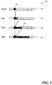
- FIG. 3 is a block diagram of an optimized morphology algorithm on a 1-dimensional (1-D) row in accordance with an embodiment of the invention
- FIG. 4 is a block diagram of a binary dilation for a 5 ⁇ 7 rectangular structuring element using an optimization algorithm in accordance with an embodiment of the invention
- FIG. 5 is a flow chart of the optimization algorithm for dilation of an image with a rectangular or cubic structuring element in accordance with an embodiment of the invention
- FIGS. 6A-6C show graphical plots of time required using the brute force algorithm, the factorization algorithm, and the optimization algorithm for a cubic structuring element as its radius increases from 1 to 10 versus time in accordance with an embodiment of the invention
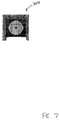
- FIG. 7 shows an example of a 2D convex structuring element in accordance with an embodiment of the invention.
- FIGS. 8A and 8B are block diagrams of an application of an optimization algorithm to apply an elliptical structuring element to an image in accordance with an embodiment of the invention.
- FIG. 9 shows a graphical representation comparing the running times for binary dilation of a 512 ⁇ 512 ⁇ 50 thresholded CT sub-image using 10 circular structuring elements with varying diameters in accordance with an embodiment of the invention and the brute force implementation.
- Computer 202 contains a processor 204 which controls the overall operation of computer 202 by executing computer program instructions which define such operation.
- the computer program instructions may be stored in a storage device 212 (e.g., magnetic disk) and loaded into memory 210 when execution of the computer program instructions is desired.
- Computer 202 also includes one or more interfaces 206 for communicating with other devices (e.g., locally or via a network).
- Computer 202 also includes input/output 208 which represents devices which allow for user interaction with the computer 202 (e.g., display, keyboard, mouse, speakers, buttons, etc.).
- input/output 208 represents devices which allow for user interaction with the computer 202 (e.g., display, keyboard, mouse, speakers, buttons, etc.).
- FIG. 2 is a high level representation of some of the components of such a computer for illustrative purposes.
- the processing steps described herein may also be implemented using dedicated hardware, the circuitry of which is configured specifically for implementing such processing steps. Alternatively, the processing steps may be implemented using various combinations of hardware and software.
- FIG. 3 shows a block diagram of a one-dimensional image canvas 300 , highlighting a pixel of interest (i.e., a focal pixel) 304 .
- An image canvas 300 is an area of pixels (or voxels) that includes the image.
- Focal pixel 304 is used to better convey how a single pixel is affected through a series of operations referred to below as an optimization algorithm, although these operations are applied to every pixel of the input image.
- a series of comparison are done between only two image elements at each step in the image canvas 300 . This is similar to having a two-element (sparse) SE for that particular step.
- Each application involves an increasing right offset between the two image elements: the logical OR (although this can be one of the logical OR, logical AND, MAX, or MIN operations) of each pixel in the row with its right neighbor (i.e., to dilate each pixel with its neighbors to the right hand side).
- the optimization algorithm exploits the idempotency property of the comparison operators (i.e., performing the operator on an element more than one time produces the same result as if the operator is applied once).
- the computer 202 performs this first operation in-place (i.e., the result of the OR operation between the focal pixel 304 and its right neighbor pixel is output at the focal pixel 304 ).
- This first dilation occurs from row 308 (i.e., no ops row) to row 312 (the 1 op row).
- row 308 i.e., no ops row
- row 312 the 1 op row.
- each pixel's output is the result of the operation between itself and a neighboring pixel.
- This is referred to below as the span of the operation—i.e., which pixels contribute to the result of the information stored in a pixel.
- the span for the focal pixel 304 in FIG. 3 is shaded. After one operation, the span of the focal pixel 304 in row 312 is itself and its right neighbor.
- the logical OR operation is performed between each pixel and the pixel one-over to the right instead of its neighboring pixel. This is shown with the arrows going from row 312 to row 316 .
- the span is four pixels. The span is four pixels because this logical OR operation in effect covers the focal pixel 304 and its right neighbor as well as the third pixel and its right neighbor.
- the next operator is performed on the fourth pixel 324 , as shown from row 316 to row 320 .
- the span grows to eight pixels.
- the focal pixel 304 being the result of the logical OR operation with its three adjacent neighbors (i.e., four pixels)
- the fourth pixel 324 is the result of the logical OR with its three adjacent neighbors (i.e., four pixels). Therefore, the span when 3 ops have been performed is eight pixels.
- the effect of the 3 ops performed on the image is the same as computing an 8-pixel wide SE on the image.
- M min CEIL(log 2 ( N ))
- the optimization algorithm is the equivalent of performing eight logical OR operations (i.e., eight dilations) in only three ops.
- the brute force technique requires eight ops to perform eight logical OR operations.
- the optimization algorithm provides significant computation savings.
- the optimization algorithm produces the same result as the brute force algorithm after two operations.
- 2 ops are needed to obtain the same output image as is obtained when applying a four pixel 1-D structuring element.
- only ops in one direction are shown. This only allows for SEs with left-sided center pixels.
- the use of a single op in the opposite direction allows for symmetric operators.
- FIG. 4 shows a block diagram of the binary dilation for a 5 ⁇ 7 rectangular structuring element using the optimization algorithm for an image canvas 400 .
- a focal pixel 404 represents a pixel of interest, but, as stated above, the operations are vectorized.
- Step 450 shows the focal pixel 404 representing a logical OR between itself and its right neighbor.
- the logical OR is again performed between the focal pixel 404 and its right neighbor. This increases the span to include two pixels to the right of the focal pixel 404 (as shown in Step 454 ) (because of vectorization).
- the focal pixel 404 contains information associated with both of the shaded pixels in Step 454 .
- each pixel has a span which is a row of length 5 .
- Step 462 the computer 202 then computes the logical OR between the focal pixel 404 and the pixel immediately beneath it. This is actually the logical OR between ten original pixel values located in a 5 ⁇ 2 neighborhood.
- the computer 202 continues to implement the optimization algorithm in Steps 466 and 470 in the same manner as in Steps 454 and 458 except the algorithm is applied vertically instead of horizontally.
- the final result is shown in step 470 .
- the focal pixel 404 represents the dilation result of a 5 ⁇ 7 rectangular structuring element with the image canvas 400 .
- the above optimization algorithm can additionally apply to a three-dimensional rectangular structuring element (e.g., 5 ⁇ 5 ⁇ 7).
- the optimization algorithms can use any of the comparison operators. Therefore, the OR operator can equally be replaced by any of the other morphological comparison operators (e.g., AND, MIN, or MAX). This ability allows application of the method to both binary and grayscale domains. The application of the method in diagonal directions allows for morphology computation of diamond-shaped structuring elements.
- FIG. 5 shows a flow chart of the optimization algorithm for dilation with a rectangular or cubic structuring element.
- the flow chart shows the generalization in the 1-D case, as the 2-D case and 3-D case are both extensions of the 1-D case (i.e., applied to a different axis). Therefore, FIG. 5 shows the optimization algorithm to efficiently obtain a logical comparison of an odd length (Q) run of binary pixels, while taking care to maintain symmetry in the final result.
- Q odd length
- N min CEIL(log 2 ( Q ))
- all ops i.e., the first N ⁇ 1 ops
- the last one i.e., N
- the last op will be expended extending the span in the reverse direction.
- N ⁇ 1 forward offsets for the cumulative logical ops because the last op will be in the reverse direction.
- the first N ⁇ 2 ops i.e., all but the last forward op
- the last forward offset is CEIL(Q/2) ⁇ 2 (N-2) .
- the computer 202 then extends the span in the reverse direction in step 512 .
- the computer 202 first determines the offset for the last op with respect to the focal pixel. This offset is ⁇ FLOOR(Q/2), with the minus sign used to denote that the offset is in the reverse direction.
- the optimization algorithms can use any of the comparison operators. Therefore, the OR operator can equally be replaced by any of the other morphological comparison operators (e.g., AND, MIN, or MAX). Further, steps 504 - 512 are repeated on the remaining axis.
- the binary dilation operator i.e., a logical OR
- the optimization algorithms can use any of the comparison operators. Therefore, the OR operator can equally be replaced by any of the other morphological comparison operators (e.g., AND, MIN, or MAX). Further, steps 504 - 512 are repeated on the remaining axis.
- FIGS. 6A-6C show timing plots using the brute force algorithm, the factorization algorithm, and the optimization algorithm for a cubic structuring element as its radius is increased from 1 to 10 versus time.
- FIG. 6A shows that the computational expense increases exponentially for the brute force algorithm as the radius of the cubic structuring element increases.
- curve 602 shows that the time required to apply the structuring element using the brute force algorithm is approximately 2000 units (e.g., seconds). The timing required by the other two methods is barely visible due to the height required to show time for the brute force method.
- FIG. 6B shows a curve 604 illustrating that the computational expense for the factorization algorithm increases linearly as the radius of the cubic structuring element increases.
- curve 604 shows that the time required to apply the structuring element using the factorization algorithm is approximately 150 units (e.g., seconds).
- the time scale has also been reduced from 0-10,000 for the brute force algorithm to 0-300 for the factorization algorithm. The time of the proposed method is again barely visible.
- FIG. 6C shows a curve 608 illustrating that the computational expense for the optimization algorithm as described above is proportional to the log of the radius of the cubic structuring element.
- curve 608 shows that the time required to apply the structuring element is approximately 12 units (e.g., seconds).
- the time scale has also been reduced from 0-300 for the factorization algorithm to 6-16 for the optimization algorithm.
- An optimization algorithm can also be applied to a digitally convex structuring element such as a 2-D circle (or ellipse) or a 3-D sphere (or ellipse).
- Convexity herein means that it is possible to draw a line from the mid-point of any pixel in a digitally convex structure (2-D) to the mid-point of any other pixel in the same structure and that line must either lie totally within the structure, or if part of that line falls outside the structure, then the area bounded by that line segment and the boundary segment of the digital structure that share common start and end points with the said line segment may not contain the mid-point of any pixel that is not part of the considered structure.
- two image canvases are needed to accomplish the morphology result using an optimization algorithm.
- the computer 202 performs the optimization algorithm iteratively, where each iteration includes a span expansion step and a pick out/compare step. At each iteration, the computer 202 “chips away” the structuring element that remains to be addressed.
- the structuring element is examined top-down—i.e., its outer-most rows/columns with unique lengths are considered. By way of convexity, each new row/column length encountered will be larger than the previous. As such, the span of the neighborhood whose comparison is represented in each pixel of the work canvas is expanded. This enables the building upon the computation that is already available by way of the previous iteration.
- the systematic composition of these intermediate results yields the desired morphology result.
- the decomposition of the structuring element is a “divide and conquer” approach to algorithms (top-down) because it sets the stage for implementing morphology within a framework that draws a close parallel with dynamic programming (bottom-up). Thus, the spatial overlap of comparisons of the original canvas in neighboring output pixels is exploited.
- FIG. 7 shows an example of a convex structuring element (a 2D digitized circle) 700 having row lengths of ⁇ 5, 9, 11, 13, 15, 17 ⁇ and column heights of ⁇ 1, 5, 9, 11, 13, 15 ⁇ .
- This structuring element 700 does not lend itself to the factorization algorithm described above.
- Two image canvases are updated at each iteration, where an interim work canvas W is first updated to reflect a rectangular span expansion (part 1 ). This is followed by updating the output image canvas O with a vectorized comparison between itself and the updated W (part 2 ).
- the input image canvas is used for O.
- a separate image canvas is used.
- FIGS. 8A and 8B show the two image canvases 804 , 808 to the optimization algorithm to apply the 2-D circular structuring element shown in FIG. 7 to an image.
- the intermediate canvas W 804 contains the results from the original image and computations on itself.
- the final output image O 808 contains operations done between W and itself.
- RSE remaining structuring element
- W is systematically compared with O. The rectangular dilation footprint of W is offset to correlate with the RSE.
- each pixel in O is updated with comparisons between itself and W values that are offset from the corresponding locations such that the outer-most unique rows and columns of the RSE may be chipped away.
- the computer 202 first performs in-place dilation on W using a structuring element that is a row of 5 pixels and then traverses that result to build up O in iteration 1 .
- the result is 4 pixels in W being combined into a single central pixel in O, similar to applying a sparse 4 pixel SE.
- This essentially “chips away” the structuring element that remains to be addressed.
- the updated RSE now has the top and bottom rows and the left-most and right-most pixel removed with respect to the original structuring element (as shown in FIG. 7 ).
- W is required to contain the dilation result of the original image with a 9 ⁇ 5 rectangular structuring element since those are the outer most row/column lengths of the RSE (i.e., the outer-most dimensions that were not covered by the structuring element in the previous step).
- W already contains the dilation result with a 5 ⁇ 1 rectangular structuring element. Therefore, the computer 202 needs to update W such that the 5 ⁇ 1 rectangular dilation footprint is expanded to a 9 ⁇ 5 rectangular dilation footprint. Note that this step reuses the data from iteration 1 , making it more computationally efficient than computing a 9 ⁇ 5 SE from scratch.
- the pixels in W are then strategically compared with the pixels in O. The dilation footprint that is reflected in each pixel of O at the end of iteration 2 is shown.
- the computer 202 expands the dilation result in W to be 13 ⁇ 9 (which are the outer most row/column lengths of the updated RSE) and do a final round of the picking/comparing with O in order to obtain the desired result.
- the parameters required to perform the outlined algorithm for any convex, X-Y symmetric structuring element are the number of iterations, the increase in the rectangular span in W for each iteration (i.e., the first part 804 ), and offsets for selecting W elements with respect to the O focal locations (the second part 808 ).
- the padding required in W i.e., the adjustment (e.g., expansion) of the structuring element
- M min CEIL(log 2 ( L now /L prev ))
- the minimum number of required morphological operations is dependent upon the current length and the previous length of the rectangular structuring element.
- the optimization algorithm described above for the 2-D circular structuring element also applies to the 3-D spherical structuring element.
- a 6 or more voxel operator would be used.
- Another example of the convex structuring element is an ellipse.
- FIG. 9 shows a graphical representation 900 of the running times for binary dilation of a 512 ⁇ 512 ⁇ 50 thresholded CT sub-image using 10 circular structuring elements with varying diameters.
- the graphical representation 900 shows a plot 904 illustrating the increase in computational time as the radius of a discrete circular structuring element increases when using a prior art (e.g., MATLAB toolbox) algorithm.
- Plot 908 shows the increase in computational time as the radius of the circular structuring element increases when using the optimization algorithm described above.
- the highest running time reached for the prior art technique is approximately 1100 seconds while the highest running time reached for the optimization algorithm is approximately 200 seconds in graphical representation 900 .
Abstract
Description
M min=CEIL(log2(N))
| 1 | 1 | 1 | 1 | structuring element | |||||||
| 0 | 0 | 0 | 0 | 0 | 1 | 0 | 0 | 0 | 0 | 0 | input image |
With the brute force approach, the center pixel of the structuring element is lined up with each pixel of the input image and then the neighborhood of the input image defined by the structuring element is ORed together. This results in an output image of:
-
- 0 0 1 1 1 1 0 0 0 0 0.
| no ops: | 0 0 0 0 0 1 0 0 0 0 0 | ||
| 1 op: | 0 0 0 0 1 1 0 0 0 0 0 | ||
| 2 ops: | 0 0 1 1 1 1 0 0 0 0 0 | ||
N min=CEIL(log2(Q))
M min=CEIL(log2(L now /L prev))
Claims (30)
Priority Applications (3)
| Application Number | Priority Date | Filing Date | Title |
|---|---|---|---|
| US11/301,393 US7974499B2 (en) | 2004-12-20 | 2005-12-13 | Method and apparatus for efficient computation of morphology operations |
| DE102005060503A DE102005060503A1 (en) | 2004-12-20 | 2005-12-15 | Method and apparatus for the efficient calculation of morphology operations |
| JP2005366597A JP2006178988A (en) | 2004-12-20 | 2005-12-20 | Method for applying morphological operation to image and system for executing morphological operation to image |
Applications Claiming Priority (2)
| Application Number | Priority Date | Filing Date | Title |
|---|---|---|---|
| US63765304P | 2004-12-20 | 2004-12-20 | |
| US11/301,393 US7974499B2 (en) | 2004-12-20 | 2005-12-13 | Method and apparatus for efficient computation of morphology operations |
Publications (2)
| Publication Number | Publication Date |
|---|---|
| US20060159360A1 US20060159360A1 (en) | 2006-07-20 |
| US7974499B2 true US7974499B2 (en) | 2011-07-05 |
Family
ID=36650724
Family Applications (1)
| Application Number | Title | Priority Date | Filing Date |
|---|---|---|---|
| US11/301,393 Expired - Fee Related US7974499B2 (en) | 2004-12-20 | 2005-12-13 | Method and apparatus for efficient computation of morphology operations |
Country Status (3)
| Country | Link |
|---|---|
| US (1) | US7974499B2 (en) |
| JP (1) | JP2006178988A (en) |
| DE (1) | DE102005060503A1 (en) |
Families Citing this family (7)
| Publication number | Priority date | Publication date | Assignee | Title |
|---|---|---|---|---|
| US7835555B2 (en) * | 2005-11-29 | 2010-11-16 | Siemens Medical Solutions Usa, Inc. | System and method for airway detection |
| US8072472B2 (en) * | 2006-06-26 | 2011-12-06 | Agfa Healthcare Inc. | System and method for scaling overlay images |
| JP4851388B2 (en) * | 2007-05-16 | 2012-01-11 | 浜松ホトニクス株式会社 | Imaging device |
| US8073281B2 (en) * | 2008-12-22 | 2011-12-06 | Canon Kabushiki Kaisha | Generating a dilation image utilizing parallel pixel processing |
| US8150193B2 (en) * | 2009-01-13 | 2012-04-03 | Canon Kabushiki Kaisha | Generating an erosion image utilizing parallel pixel processing |
| WO2014153690A1 (en) * | 2013-03-29 | 2014-10-02 | Intel Corporation | Simd algorithm for image dilation and erosion processing |
| CN105551002B (en) * | 2015-12-17 | 2018-04-20 | 重庆大学 | A kind of morphological image filtering method |
Citations (4)
| Publication number | Priority date | Publication date | Assignee | Title |
|---|---|---|---|---|
| US4866785A (en) * | 1985-12-27 | 1989-09-12 | International Business Machines Corporation | Multi-valved image processing apparatus and method |
| US6175655B1 (en) * | 1996-09-19 | 2001-01-16 | Integrated Medical Systems, Inc. | Medical imaging system for displaying, manipulating and analyzing three-dimensional images |
| US6282328B1 (en) * | 1998-01-28 | 2001-08-28 | Cognex Corporation | Machine vision systems and methods for morphological transformation of an image with non-uniform offsets |
| US6993170B2 (en) * | 1999-06-23 | 2006-01-31 | Icoria, Inc. | Method for quantitative analysis of blood vessel structure |
-
2005
- 2005-12-13 US US11/301,393 patent/US7974499B2/en not_active Expired - Fee Related
- 2005-12-15 DE DE102005060503A patent/DE102005060503A1/en not_active Withdrawn
- 2005-12-20 JP JP2005366597A patent/JP2006178988A/en active Pending
Patent Citations (4)
| Publication number | Priority date | Publication date | Assignee | Title |
|---|---|---|---|---|
| US4866785A (en) * | 1985-12-27 | 1989-09-12 | International Business Machines Corporation | Multi-valved image processing apparatus and method |
| US6175655B1 (en) * | 1996-09-19 | 2001-01-16 | Integrated Medical Systems, Inc. | Medical imaging system for displaying, manipulating and analyzing three-dimensional images |
| US6282328B1 (en) * | 1998-01-28 | 2001-08-28 | Cognex Corporation | Machine vision systems and methods for morphological transformation of an image with non-uniform offsets |
| US6993170B2 (en) * | 1999-06-23 | 2006-01-31 | Icoria, Inc. | Method for quantitative analysis of blood vessel structure |
Non-Patent Citations (1)
| Title |
|---|
| Dan S. Bloomberg, "Implementation Efficiency of Binary Morphology", International Symposium for Mathematical Morphology VI, Sydney, Australia, Apr. 3-5, 2002. |
Also Published As
| Publication number | Publication date |
|---|---|
| JP2006178988A (en) | 2006-07-06 |
| DE102005060503A1 (en) | 2006-07-27 |
| US20060159360A1 (en) | 2006-07-20 |
Similar Documents
| Publication | Publication Date | Title |
|---|---|---|
| US7974499B2 (en) | Method and apparatus for efficient computation of morphology operations | |
| US6754374B1 (en) | Method and apparatus for processing images with regions representing target objects | |
| US6813373B1 (en) | Image segmentation of embedded shapes using constrained morphing | |
| US7995810B2 (en) | System and methods for image segmentation in n-dimensional space | |
| JP6505124B2 (en) | Automatic contour extraction system and method in adaptive radiation therapy | |
| US8270696B2 (en) | Image slice segmentation using midpoints of contour anchor points | |
| JP4152648B2 (en) | Method for segmenting a 3D image contained in an object | |
| US20070109299A1 (en) | Surface-based characteristic path generation | |
| EP0602730A2 (en) | Registration of Volumetric images which are relatively elastically deformed by matching surfaces | |
| US20020097912A1 (en) | Method of computing sub-pixel euclidean distance maps | |
| JPH0852127A (en) | Picture processing method and device to automatically detectkey point which is positioned on contour of object | |
| US8300975B2 (en) | Piecewise smooth Mumford-Shah on an arbitrary graph | |
| JPH05205105A (en) | Thinning of character using action by set of locally independent conflict process | |
| Mahmoudi et al. | GPU-based segmentation of cervical vertebra in X-ray images | |
| US7650025B2 (en) | System and method for body extraction in medical image volumes | |
| Schenk et al. | Local-cost computation for efficient segmentation of 3D objects with live wire | |
| US7668349B2 (en) | Three-dimensional segmentation using deformable surfaces | |
| Pikaz et al. | Using simple decomposition for smoothing and feature point detection of noisy digital curves | |
| US7483023B2 (en) | Model based adaptive multi-elliptical approach: a one click 3D segmentation approach | |
| Soussen et al. | Polygonal and polyhedral contour reconstruction in computed tomography | |
| US6718054B1 (en) | MRA segmentation using active contour models | |
| van Ginneken et al. | Automatic delineation of ribs in frontal chest radiographs | |
| US6693631B2 (en) | System and method for multi-resolution fairing of non-manifold models | |
| Wei et al. | Morphology-preserving smoothing on polygonized isosurfaces of inhomogeneous binary volumes | |
| Bischoff et al. | Parameterization-free active contour models with topology control |
Legal Events
| Date | Code | Title | Description |
|---|---|---|---|
| AS | Assignment |
Owner name: SIEMENS CORPORATE RESEARCH, INC., NEW JERSEY Free format text: ASSIGNMENT OF ASSIGNORS INTEREST;ASSIGNORS:VAZ, MICHAEL;KIRALY, ATILLA PETER;SIGNING DATES FROM 20060224 TO 20060313;REEL/FRAME:017380/0394 Owner name: SIEMENS CORPORATE RESEARCH, INC., NEW JERSEY Free format text: ASSIGNMENT OF ASSIGNORS INTEREST;ASSIGNORS:VAZ, MICHAEL;KIRALY, ATILLA PETER;REEL/FRAME:017380/0394;SIGNING DATES FROM 20060224 TO 20060313 |
|
| AS | Assignment |
Owner name: SIEMENS MEDICAL SOLUTIONS USA, INC.,PENNSYLVANIA Free format text: ASSIGNMENT OF ASSIGNORS INTEREST;ASSIGNOR:SIEMENS CORPORATE RESEARCH, INC.;REEL/FRAME:019309/0669 Effective date: 20070430 Owner name: SIEMENS MEDICAL SOLUTIONS USA, INC., PENNSYLVANIA Free format text: ASSIGNMENT OF ASSIGNORS INTEREST;ASSIGNOR:SIEMENS CORPORATE RESEARCH, INC.;REEL/FRAME:019309/0669 Effective date: 20070430 |
|
| REMI | Maintenance fee reminder mailed | ||
| LAPS | Lapse for failure to pay maintenance fees | ||
| STCH | Information on status: patent discontinuation |
Free format text: PATENT EXPIRED DUE TO NONPAYMENT OF MAINTENANCE FEES UNDER 37 CFR 1.362 |
|
| FP | Lapsed due to failure to pay maintenance fee |
Effective date: 20150705 |