US7975075B2 - Data communication system and method - Google Patents
Data communication system and method Download PDFInfo
- Publication number
- US7975075B2 US7975075B2 US12/074,805 US7480508A US7975075B2 US 7975075 B2 US7975075 B2 US 7975075B2 US 7480508 A US7480508 A US 7480508A US 7975075 B2 US7975075 B2 US 7975075B2
- Authority
- US
- United States
- Prior art keywords
- external module
- main device
- identification information
- data communication
- port
- Prior art date
- Legal status (The legal status is an assumption and is not a legal conclusion. Google has not performed a legal analysis and makes no representation as to the accuracy of the status listed.)
- Expired - Fee Related, expires
Links
Images


Classifications
-
- H—ELECTRICITY
- H04—ELECTRIC COMMUNICATION TECHNIQUE
- H04L—TRANSMISSION OF DIGITAL INFORMATION, e.g. TELEGRAPHIC COMMUNICATION
- H04L43/00—Arrangements for monitoring or testing data switching networks
- H04L43/08—Monitoring or testing based on specific metrics, e.g. QoS, energy consumption or environmental parameters
- H04L43/0805—Monitoring or testing based on specific metrics, e.g. QoS, energy consumption or environmental parameters by checking availability
- H04L43/0811—Monitoring or testing based on specific metrics, e.g. QoS, energy consumption or environmental parameters by checking availability by checking connectivity
-
- H—ELECTRICITY
- H04—ELECTRIC COMMUNICATION TECHNIQUE
- H04B—TRANSMISSION
- H04B10/00—Transmission systems employing electromagnetic waves other than radio-waves, e.g. infrared, visible or ultraviolet light, or employing corpuscular radiation, e.g. quantum communication
- H04B10/11—Arrangements specific to free-space transmission, i.e. transmission through air or vacuum
- H04B10/114—Indoor or close-range type systems
- H04B10/1143—Bidirectional transmission
-
- H—ELECTRICITY
- H04—ELECTRIC COMMUNICATION TECHNIQUE
- H04B—TRANSMISSION
- H04B3/00—Line transmission systems
- H04B3/02—Details
- H04B3/46—Monitoring; Testing
-
- H—ELECTRICITY
- H04—ELECTRIC COMMUNICATION TECHNIQUE
- H04L—TRANSMISSION OF DIGITAL INFORMATION, e.g. TELEGRAPHIC COMMUNICATION
- H04L65/00—Network arrangements, protocols or services for supporting real-time applications in data packet communication
Definitions
- the present invention relates to a method and system for performing serial data communication between a main device and an external module connected to the main device.
- FIG. 1 is a block diagram illustrating a conventional multiple serial communication apparatus disclosed in Korean Patent Application No. 1998-0059854.
- the multiple serial communication apparatus changes the use of a universal asynchronous receiver/transmitter (UART) port 11 that performs RS232 communication according to the state of a port input/output (PIO) 12 in a communication control module 10 .
- the multiple serial communication apparatus employed in a control board of a mobile communication system recognizes the RS232 communication according to the connection state of a cable, outputs a logical LOW state of the PIO 12 of the communication control module 10 , and uses the UART port 11 for RS232 communication under the control of a selector 80 .
- the apparatus may output a logical HIGH state of the PIO 12 of the communication control module 10 , and use the UART port 11 for infrared communication under the control of the selector 80 .
- Two UART serial communication pins Rx and Tx are conventionally used to perform standardized serial communication. For example, if it is possible to connect a device A to modules B and C via RS232 communication, the modules B and C that are connected to the device A perform communication, whereas the device A merely receives data but does not determine whether the module B or C is actually connected to device A. Thus, another detection pin is needed to recognize such a connection.
- the present invention provides a method and system for communicating data that is capable of recognizing the type of external module connected to a main device by using two universal asynchronous receiver/transmitter (UART) serial communication pins Rx and Tx only, without the need for another detection pin.
- UART universal asynchronous receiver/transmitter
- an embodiment of the present invention provides a data communication method comprising a main device and an external module connected to the main device and communicating data with the main device, such that the external module transmits its identification information to the main device before the external module and the main device communicate the data therebetween, and the main device receives the identification information from the external module, confirms its connection to the external module, and transmits an identification information confirmation signal to the external module.
- the external module may communicate the data with the main device after receiving the identification information confirmation signal, and may periodically transmit its identification information to the main device.
- the main device may determine a type of the external module from the identification information and converts its mode to a communication mode of the external module.
- the identification information received by the main device may comprise at least a type of the external module.
- the identification information confirmation signal transmitted by the main device may comprise at least a signal indicating that the main device is successfully connected to the external module.
- Another embodiment of the present invention provides a data communication system comprising a main device including receiver/transmitter ports used to perform serial data communication with an external module, and an external module including receiver/transmitter ports used to perform serial data communication with the main device.
- the transmitter port of the external module transmits its identification information to the receiver port of the main device before the serial data communication is performed, such that the transmitter port of the main device transmits a signal, indicating that the main device is connected to the external module, to the receiver port of the external module.
- the receiver/transmitter ports of the main device and the receiver/transmitter ports of the external module may perform serial data communication therebetween after receiving/transmitting the identification information and the signal indicating that the main device has been connected to the external module.
- the transmitter port of the external module may periodically transmit its identification information to the receiver port of the main device.
- the identification information received by the receiver port of the main device may comprise information on a receiver, a serial number, version information, and category of the external module.
- the signal indicating that the main device is connected to the external module and transmitted by the transmitter port of the main device may comprise information on a transmitter, the serial number, the version information, and the category of the external module.
- Another embodiment of the present invention provides a method of communicating data between a main device and an external module connected to the main device.
- the method comprises operating the external module to transmit its identification information to the main device, and operating the main device to receive the identification information from the external module confirming its connection to the external module, and transmit an identification information confirmation signal to the external module. If the external module receives the identification information confirmation signal, data is communicated between the external module and the main device.
- the identification information may be periodically transmitted to the main device.
- the identification information may comprise at least a type of the external module.
- the identification information confirmation signal may comprise at least a signal indicating that the main device has been successfully connected to the external module.
- FIG. 1 is a block diagram illustrating a conventional multiple serial communication apparatus as disclosed in Korean Patent Application No. 1998-0059854;
- FIG. 2 is a block diagram of an example of a data communication system according to an embodiment of the present invention.
- FIGS. 3A through 3C illustrate examples of a format of identification information received by a main device from an external module in FIG. 2 according to an embodiment of the present invention
- FIGS. 4A through 4C illustrate examples of a format of an identification information confirmation signal transmitted by the main device to the external module in FIG. 2 according to an embodiment of the present invention.
- FIG. 5 is a flowchart of an example of a data communication method according to an embodiment of the present invention.
- FIG. 2 is a block diagram of a data communication system according to an embodiment of the present invention.
- the data communication system comprises a main device 200 and an external module 210 .
- the main device 200 may be a digital camera, a terminal, a portable terminal, or the like that employs a 24-pin connector following 24 pin standards defined by the telecommunication technology association (TTA), during universal asynchronous receiver/transmitter (UART) serial communication.
- TTA telecommunication technology association
- UART universal asynchronous receiver/transmitter
- the external module 210 that is connected to the main device 200 and performs serial data communication with the main device 200 may be a global positioning system (GPS) module, a Bluetooth module, or an infrared data association (IrDA) module.
- GPS global positioning system
- IrDA infrared data association
- the main device 200 and the external module 210 can be connected via a wired cable (not shown) or wirelessly to perform serial data communication.
- the main device 200 is the digital camera
- the external module 210 is the GPS module
- the digital camera and the GPS module are wired or wirelessly connected so that the digital camera receives location information stored in the GPS module and stores location information received when an image file taken by the digital camera is stored.
- the main device 200 is the portable terminal
- the external module 210 is the Bluetooth module
- the portable terminal receives and stores a predetermined image signal from the Bluetooth module.
- the main device 200 in this example includes a controller 201 , which controls the main device 200 and comprises a transmitter port (hereinafter referred to as a Tx port) 203 and a receiver port (hereinafter referred to as an Rx port) 205 for performing the serial data communication.
- the external module 210 in this example includes a controller 211 , which controls the external module 210 and comprises a Tx port 213 and an Rx port 201 for performing the serial data communication.
- the Rx port 205 of the main device 200 merely receives data from the external module, but need not be informed of what type of the external module 210 is connected to the main device 200 . Therefore, according to an embodiment of the present embodiment of the present invention, the main device 200 recognizes the type of the external module 210 so as to display a current data communication state as an on screen display (OSD), or control the state of the main device 200 in conformity with the external module 210 . Hence, the Rx port 205 of the main device 200 periodically receives identification information of the external module 210 from the Tx port 123 of the external module 210 before serial data communication is performed.
- OSD on screen display
- FIGS. 3A through 3C illustrate an example of a format of identification information received by the main device 200 from the external module 210 according to an embodiment of the present invention.
- the format of the identification information includes at least a category of the external module 210 , that is, the type of the external module 210 connected to the main device 200 .
- the type of the external module 210 may be the GPS module, Bluetooth module, or a IrDA module as shown in FIGS. 3A through 3C , or any other suitable type of module.
- the format of the identification information comprises an identifier indicating that the main device 200 receives the identification information, a serial number, version information, and category of the external module 210 .
- the identification information “$0101gps”, “$” indicates the identifier indicating that the main device 200 receives the identification information
- the first “01” indicates the serial number of the external module 210
- the second “01” indicates the version information of the external module 210
- “gps” indicates that the category of the external module 210 is the GPS module.
- identification information “$0703blu” indicates the identifier indicating that the main device 200 receives the identification information
- “07” indicates the serial number of the external module 210
- “03” indicates the version information of the external module 210
- “blu” indicates that the category of the external module 210 is the Bluetooth module.
- identification information “$0502ird” indicates the identifier indicating that the main device 200 receives the identification information
- “05” indicates the serial number of the external module 210
- 02 indicates the version information of the external module 210
- “ird” indicates that the category of the external module 210 is the IrDA module.
- the Rx port 205 of the main device 200 receives the identification information shown in FIGS. 3A through 3C from the Tx port 213 of the external module 210 , performs signal processing to output a current communication state as an OSD, and converts the main device 200 into a communication mode of the external module 210 to perform serial data communication. Thereafter, the Tx port 203 of the main device 200 transmits an identification information confirmation signal to the Rx port 215 of the external module 210 .
- the identification information confirmation signal is a signal indicating that the main device 200 is successfully connected to the external module 210 , so that the main device 200 and the external module 210 can perform serial data communication therebetween.
- FIGS. 4A through 4C illustrate an example of a format of the identification information confirmation signal transmitted by the main device 200 to the external module 210 according to an embodiment of the present invention.
- the identification information confirmation signal includes at least an identifier indicating that the external module 210 has been successfully connected to the main device 200 .
- the format of the identification information confirmation signal comprises the identifier indicating that the main device 200 transmits the identification information confirmation signal to the external module 210 that has been successfully connected to the main device 200 , a serial number, version information, and category of the external module 210 .
- an identification information confirmation signal “% 0101gps” indicates the identifier indicating that the main device 200 transmits the identification information confirmation signal to the external module 210 that is a GPS module and has been successfully connected to the main device 200
- the first “01” indicates the serial number of the external module 210
- the second “01” indicates the version information of the external module 210
- “gps” indicates that the category of the external module 210 is the GPS module.
- an identification information confirmation signal “% 0703blu” indicates the identifier indicating that the main device 200 transmits the identification information confirmation signal to the external module 210 that is a Bluetooth module and has been successfully connected to the main device 200 , “07” indicates the serial number of the external module 210 , “03” indicates the version information of the external module 210 , and “blu” indicates that the category of the external module 210 is the Bluetooth module.
- an identification information confirmation signal “% 0502ird” indicates the identifier indicating that the main device 200 transmits the identification information confirmation signal to the external module 210 that is an IrDA module and has been successfully connected to the main device 200 , “05” indicates the serial number of the external module 210 , “02” indicates the version information of the external module 210 , and “ird” indicates that the category of the external module 210 is the IrDA module.
- the main device 200 and the external module 210 perform serial data communication therebetween.
- the external module 210 periodically requests the main device 200 to transmit the identification information confirmation signal. Even after a predetermined period of time elapses, if the Rx port 215 of the external module 210 does not receive the identification information confirmation signal from the Tx port 203 of the main device 200 , the main device 200 fails to recognize the external module 210 . Thus, the main device 200 and the external module 210 cannot perform serial data communication therebetween.
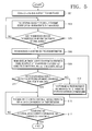
- FIG. 5 is a flowchart of an example of a method of communicating data between the main device 200 and the external module 210 according to an embodiment of the present invention.
- the external module 210 is connected to the main device 200 in operation 501 .
- the external module 210 can be connected to the main device 200 via a wired cable or wirelessly.
- the external device 210 periodically transmits its identification information to the main device 200 in operation 503 .
- the Rx port 205 of the main device 200 periodically receives the identification information from the Tx port 123 of the external module 210 .
- the format of the identification information of the external module 210 that the main device 200 receives includes at least a category of the external module 210 , that is, the type of the external module 210 connected to the main device 200 .
- the format of the identification information comprises an identifier indicating that the main device 200 receives the identification information, a serial number, version information, and category of the external module 210 .
- the main device 200 analyzes the identification information of the external module 210 in operation 507 .
- the main device 200 confirms the serial number, version information, and category of the external module 210 from the identification information.
- the main device 200 performs signal processing to output a current communication state as an OSD, and converts the main device 200 into a communication mode of the external module 210 to perform serial data communication.
- the main device 200 transmits an identification information confirmation signal indicating that the main device 200 is successfully connected to the external module 210 to the external module 210 in operation 509 .
- the Tx port 203 of the main device 200 transmits the identification information confirmation signal to the Rx port 215 of the external module 210 .
- the identification information confirmation signal is a signal indicating that the main device 200 has been successfully connected to the external module 210 , so that the main device 200 and the external module 210 can perform serial data communication therebetween.
- the identification information confirmation signal includes at least an identifier indicating that the external module 210 is successfully connected to the main device 200 .
- the format of the identification information confirmation signal comprises the identifier indicating that the main device 200 transmits the identification information confirmation signal to the external module 210 that has been successfully connected to the main device 200 , a serial number, version information; and category of the external module 210 .
- the external module 210 receives the identification information confirmation signal from the main device 200 . If the external module 210 does not receive the identification information confirmation signal from the main device 200 , the external module 210 periodically requests the main device 200 to transmit the identification information confirmation signal in operation 513 ). After a predetermined period of time elapses, if the Rx port 215 of the external module 210 does not receive the identification information confirmation signal from the Tx port 203 of the main device 200 , it is determined that the main device 200 has failed to recognize the external module 210 . Thus, the main device 200 and the external module 210 cannot perform serial data communication therebetween.
- the main device 200 and the external module 210 perform serial data communication therebetween in operation 515 .
- the main device 200 is a digital camera
- the external module 210 is a GPS module
- the digital camera and the GPS module are wired or wirelessly connected so that the digital camera receives location information stored in the GPS module and stores location information received when an image file taken by the digital camera is stored.
- the main device 200 is the portable terminal
- the external module 210 is the Bluetooth module
- the portable terminal receives and stores a predetermined image signal from the Bluetooth module. Thereafter, the main device 200 and the external module 210 completely perform serial data communication therebetween in operation 517 o.
- the embodiments of the present invention can recognize the type of an external module connected to a main device using two universal asynchronous receiver/transmitter (UART) serial communication pins Rx and Tx only, without the allocation of a detection pin.
- UART universal asynchronous receiver/transmitter
Landscapes
- Engineering & Computer Science (AREA)
- Computer Networks & Wireless Communication (AREA)
- Signal Processing (AREA)
- Physics & Mathematics (AREA)
- Electromagnetism (AREA)
- Multimedia (AREA)
- Environmental & Geological Engineering (AREA)
- Mobile Radio Communication Systems (AREA)
- Information Transfer Systems (AREA)
- Communication Control (AREA)
Abstract
Description
Claims (23)
Applications Claiming Priority (2)
| Application Number | Priority Date | Filing Date | Title |
|---|---|---|---|
| KR1020070062486A KR101365437B1 (en) | 2007-06-25 | 2007-06-25 | System and method for data communication |
| KR10-2007-0062486 | 2007-06-25 |
Publications (2)
| Publication Number | Publication Date |
|---|---|
| US20080320174A1 US20080320174A1 (en) | 2008-12-25 |
| US7975075B2 true US7975075B2 (en) | 2011-07-05 |
Family
ID=40137678
Family Applications (1)
| Application Number | Title | Priority Date | Filing Date |
|---|---|---|---|
| US12/074,805 Expired - Fee Related US7975075B2 (en) | 2007-06-25 | 2008-03-06 | Data communication system and method |
Country Status (3)
| Country | Link |
|---|---|
| US (1) | US7975075B2 (en) |
| KR (1) | KR101365437B1 (en) |
| CN (1) | CN101335570B (en) |
Cited By (4)
| Publication number | Priority date | Publication date | Assignee | Title |
|---|---|---|---|---|
| US20110058220A1 (en) * | 2008-06-30 | 2011-03-10 | Canon Kabushiki Kaisha | Communication system, communication apparatus, and communication control method |
| US20120154605A1 (en) * | 2010-12-15 | 2012-06-21 | Eka Technologies, Inc. | Wireless data module for imaging systems |
| US20140208416A1 (en) * | 2008-09-08 | 2014-07-24 | Apple Inc. | Cross transport authentication |
| US9754099B2 (en) | 2005-01-07 | 2017-09-05 | Apple Inc. | Accessory authentication for electronic devices |
Families Citing this family (4)
| Publication number | Priority date | Publication date | Assignee | Title |
|---|---|---|---|---|
| US10060173B2 (en) * | 2011-05-24 | 2018-08-28 | Overhead Door Corporation | Multiple speed profiles in barrier operator systems |
| KR101952213B1 (en) * | 2012-04-27 | 2019-02-26 | 삼성전자 주식회사 | Method and apparatus for data communication using digital image processing |
| JP6155953B2 (en) | 2013-08-13 | 2017-07-05 | カシオ計算機株式会社 | Information communication apparatus, information communication system, information communication method, and program |
| US9882748B2 (en) * | 2014-03-10 | 2018-01-30 | Intel Corporation | Technologies for configuring transmitter equalization in a communication system |
Citations (14)
| Publication number | Priority date | Publication date | Assignee | Title |
|---|---|---|---|---|
| US5351041A (en) * | 1990-10-25 | 1994-09-27 | Pioneer Electronic Corporation | Method of data communication in communication network on automobile |
| JPH0721101A (en) | 1993-06-30 | 1995-01-24 | Nippondenso Co Ltd | Serial communication processor |
| US5884102A (en) * | 1997-05-30 | 1999-03-16 | Intel Corporation | Method and apparatus for a configurable means of connection between an embedded processor and a personal computer |
| KR20000043472A (en) | 1998-12-29 | 2000-07-15 | 김영환 | Multiple serial communication apparatus |
| US6470404B1 (en) * | 1998-09-10 | 2002-10-22 | Hyundai Electronics Industries Co., Ltd. | Asynchronous communication device |
| US20040035930A1 (en) * | 2001-10-31 | 2004-02-26 | Shigeru Arisawa | Ic chip and information processing terminal |
| US20040153809A1 (en) * | 2002-05-30 | 2004-08-05 | Fujitsu Limited | Bus analyzer capable of managing device information |
| US20050055471A1 (en) * | 2003-09-09 | 2005-03-10 | Transact Technologies Incorporated | Standard configurable universal serial bus (USB) device identifier |
| US7047324B2 (en) * | 2003-03-12 | 2006-05-16 | Lite-On It Corporation | System and method of operation information collection for CD-ROM drives |
| US7206874B2 (en) * | 2004-01-27 | 2007-04-17 | Inventec Corporation | Status display-enabled connector for a universal asynchronous receiver/transmitter |
| US20070255860A1 (en) * | 2006-04-28 | 2007-11-01 | Mediatek Inc. | Systems and methods for managing mass storage devices in electronic devices |
| US7433990B2 (en) * | 2006-01-24 | 2008-10-07 | Standard Microsystems Corporation | Transferring system information via universal serial bus (USB) |
| US20080263243A1 (en) * | 2007-04-18 | 2008-10-23 | Cypress Semiconductor Corp. | Specialized universal serial bus controller |
| US20090024757A1 (en) * | 2004-07-30 | 2009-01-22 | Proctor David W | Automatic Protocol Determination For Portable Devices Supporting Multiple Protocols |
Family Cites Families (3)
| Publication number | Priority date | Publication date | Assignee | Title |
|---|---|---|---|---|
| KR20040091996A (en) * | 2003-04-23 | 2004-11-03 | 삼성전자주식회사 | Apparatus, system and method for identification of controlled device using RF signal |
| JP2005209057A (en) * | 2004-01-26 | 2005-08-04 | Matsushita Electric Ind Co Ltd | Data communication method |
| KR100678099B1 (en) * | 2005-04-06 | 2007-02-02 | 삼성전자주식회사 | Device and?method for displaying?information in bluetooth of wireless terminal |
-
2007
- 2007-06-25 KR KR1020070062486A patent/KR101365437B1/en not_active IP Right Cessation
-
2008
- 2008-03-06 US US12/074,805 patent/US7975075B2/en not_active Expired - Fee Related
- 2008-04-28 CN CN2008100948367A patent/CN101335570B/en not_active Expired - Fee Related
Patent Citations (14)
| Publication number | Priority date | Publication date | Assignee | Title |
|---|---|---|---|---|
| US5351041A (en) * | 1990-10-25 | 1994-09-27 | Pioneer Electronic Corporation | Method of data communication in communication network on automobile |
| JPH0721101A (en) | 1993-06-30 | 1995-01-24 | Nippondenso Co Ltd | Serial communication processor |
| US5884102A (en) * | 1997-05-30 | 1999-03-16 | Intel Corporation | Method and apparatus for a configurable means of connection between an embedded processor and a personal computer |
| US6470404B1 (en) * | 1998-09-10 | 2002-10-22 | Hyundai Electronics Industries Co., Ltd. | Asynchronous communication device |
| KR20000043472A (en) | 1998-12-29 | 2000-07-15 | 김영환 | Multiple serial communication apparatus |
| US20040035930A1 (en) * | 2001-10-31 | 2004-02-26 | Shigeru Arisawa | Ic chip and information processing terminal |
| US20040153809A1 (en) * | 2002-05-30 | 2004-08-05 | Fujitsu Limited | Bus analyzer capable of managing device information |
| US7047324B2 (en) * | 2003-03-12 | 2006-05-16 | Lite-On It Corporation | System and method of operation information collection for CD-ROM drives |
| US20050055471A1 (en) * | 2003-09-09 | 2005-03-10 | Transact Technologies Incorporated | Standard configurable universal serial bus (USB) device identifier |
| US7206874B2 (en) * | 2004-01-27 | 2007-04-17 | Inventec Corporation | Status display-enabled connector for a universal asynchronous receiver/transmitter |
| US20090024757A1 (en) * | 2004-07-30 | 2009-01-22 | Proctor David W | Automatic Protocol Determination For Portable Devices Supporting Multiple Protocols |
| US7433990B2 (en) * | 2006-01-24 | 2008-10-07 | Standard Microsystems Corporation | Transferring system information via universal serial bus (USB) |
| US20070255860A1 (en) * | 2006-04-28 | 2007-11-01 | Mediatek Inc. | Systems and methods for managing mass storage devices in electronic devices |
| US20080263243A1 (en) * | 2007-04-18 | 2008-10-23 | Cypress Semiconductor Corp. | Specialized universal serial bus controller |
Cited By (7)
| Publication number | Priority date | Publication date | Assignee | Title |
|---|---|---|---|---|
| US9754099B2 (en) | 2005-01-07 | 2017-09-05 | Apple Inc. | Accessory authentication for electronic devices |
| US10049206B2 (en) | 2005-01-07 | 2018-08-14 | Apple Inc. | Accessory authentication for electronic devices |
| US20110058220A1 (en) * | 2008-06-30 | 2011-03-10 | Canon Kabushiki Kaisha | Communication system, communication apparatus, and communication control method |
| US8953198B2 (en) * | 2008-06-30 | 2015-02-10 | Canon Kabushiki Kaisha | Communication system, communication apparatus, and communication control method |
| US20140208416A1 (en) * | 2008-09-08 | 2014-07-24 | Apple Inc. | Cross transport authentication |
| US20120154605A1 (en) * | 2010-12-15 | 2012-06-21 | Eka Technologies, Inc. | Wireless data module for imaging systems |
| US8477215B2 (en) * | 2010-12-15 | 2013-07-02 | Eka Technologies, Inc. | Wireless data module for imaging systems |
Also Published As
| Publication number | Publication date |
|---|---|
| KR20080113693A (en) | 2008-12-31 |
| KR101365437B1 (en) | 2014-02-19 |
| US20080320174A1 (en) | 2008-12-25 |
| CN101335570B (en) | 2013-10-30 |
| CN101335570A (en) | 2008-12-31 |
Similar Documents
| Publication | Publication Date | Title |
|---|---|---|
| US7975075B2 (en) | Data communication system and method | |
| US9812006B1 (en) | System and method for integrating infrared remote controls of home appliances | |
| EP3141974A1 (en) | Personal vehicle diagnosis system and method based on mobile intelligent terminal | |
| KR101956574B1 (en) | Apparatus and method for identifying operating system of host device in portable terminal | |
| US20150109640A1 (en) | Communication device and control method thereof | |
| RU2011103134A (en) | CONFIGURATION DEVICE, IMAGE OUTPUT DEVICE, METHODS OF MANAGING THEM AND PROGRAM | |
| US9614986B2 (en) | Data output apparatus, method of controlling same and output system | |
| US20130088649A1 (en) | Remote control apparatus, remote control method and display apparatus | |
| US10082899B2 (en) | Electronic apparatus with touch panel and method for updating touch panel | |
| US11128527B2 (en) | Installation support device and method for installation process support for an automation system | |
| US20110150182A1 (en) | Radiation imaging apparatus | |
| KR101100296B1 (en) | SATA device having self-test function for OOB signaling | |
| US9456338B2 (en) | Control apparatus and wireless communication system | |
| KR102508074B1 (en) | Continuous communication method and apparatus of contactless communication device | |
| CN112752083B (en) | Online matching method and computer-readable storage medium | |
| US10606781B2 (en) | Data transmission system, projector, and data transmission method including first apparatus with first communication part and second apparatus with second communication part | |
| CN115167330A (en) | Communication error diagnosis apparatus for vehicle, system having the same, and method thereof | |
| CN114987779A (en) | Control method and device of lens module, aircraft, flight system and medium | |
| CN116048290B (en) | Data transmission method and device | |
| KR102314814B1 (en) | Apparatus and method for linking data based the open standard in the wearable communication system | |
| CN113030560B (en) | Mobile terminal, test instrument and test system | |
| CN101064811B (en) | Electronic device and method for communicating with external connection module | |
| KR20160115495A (en) | Apparatus and method for detecting and converting the signal of HDMI and DVI to Displayport signal | |
| US20230315666A1 (en) | Method for recognizing another electronic device by using plurality of interfaces, and electronic device therefor | |
| JP2016115045A (en) | Communication module and module testing system |
Legal Events
| Date | Code | Title | Description |
|---|---|---|---|
| AS | Assignment |
Owner name: SAMSUNG TECHWIN CO., LTD., KOREA, REPUBLIC OF Free format text: ASSIGNMENT OF ASSIGNORS INTEREST;ASSIGNORS:LEE, JONG-TAE;HAN, JAE-HO;REEL/FRAME:020797/0246 Effective date: 20080306 |
|
| AS | Assignment |
Owner name: SAMSUNG DIGITAL IMAGING CO., LTD., KOREA, REPUBLIC Free format text: ASSIGNMENT OF ASSIGNORS INTEREST;ASSIGNOR:SAMSUNG TECHWIN CO., LTD.;REEL/FRAME:022951/0956 Effective date: 20090619 Owner name: SAMSUNG DIGITAL IMAGING CO., LTD.,KOREA, REPUBLIC Free format text: ASSIGNMENT OF ASSIGNORS INTEREST;ASSIGNOR:SAMSUNG TECHWIN CO., LTD.;REEL/FRAME:022951/0956 Effective date: 20090619 |
|
| FEPP | Fee payment procedure |
Free format text: PAYOR NUMBER ASSIGNED (ORIGINAL EVENT CODE: ASPN); ENTITY STATUS OF PATENT OWNER: LARGE ENTITY |
|
| AS | Assignment |
Owner name: SAMSUNG ELECTRONICS CO., LTD., KOREA, REPUBLIC OF Free format text: MERGER;ASSIGNOR:SAMSUNG DIGITAL IMAGING CO., LTD.;REEL/FRAME:026128/0759 Effective date: 20100402 |
|
| STCF | Information on status: patent grant |
Free format text: PATENTED CASE |
|
| FPAY | Fee payment |
Year of fee payment: 4 |
|
| MAFP | Maintenance fee payment |
Free format text: PAYMENT OF MAINTENANCE FEE, 8TH YEAR, LARGE ENTITY (ORIGINAL EVENT CODE: M1552); ENTITY STATUS OF PATENT OWNER: LARGE ENTITY Year of fee payment: 8 |
|
| FEPP | Fee payment procedure |
Free format text: MAINTENANCE FEE REMINDER MAILED (ORIGINAL EVENT CODE: REM.); ENTITY STATUS OF PATENT OWNER: LARGE ENTITY |
|
| LAPS | Lapse for failure to pay maintenance fees |
Free format text: PATENT EXPIRED FOR FAILURE TO PAY MAINTENANCE FEES (ORIGINAL EVENT CODE: EXP.); ENTITY STATUS OF PATENT OWNER: LARGE ENTITY |
|
| STCH | Information on status: patent discontinuation |
Free format text: PATENT EXPIRED DUE TO NONPAYMENT OF MAINTENANCE FEES UNDER 37 CFR 1.362 |
|
| FP | Lapsed due to failure to pay maintenance fee |
Effective date: 20230705 |