US7976337B1 - Palmtop computer docking system with USB cable assembly - Google Patents
Palmtop computer docking system with USB cable assembly Download PDFInfo
- Publication number
- US7976337B1 US7976337B1 US10/222,123 US22212302A US7976337B1 US 7976337 B1 US7976337 B1 US 7976337B1 US 22212302 A US22212302 A US 22212302A US 7976337 B1 US7976337 B1 US 7976337B1
- Authority
- US
- United States
- Prior art keywords
- cable
- connector
- power
- cable assembly
- computing device
- Prior art date
- Legal status (The legal status is an assumption and is not a legal conclusion. Google has not performed a legal analysis and makes no representation as to the accuracy of the status listed.)
- Expired - Fee Related, expires
Links
Images


Classifications
-
- G—PHYSICS
- G06—COMPUTING; CALCULATING OR COUNTING
- G06F—ELECTRIC DIGITAL DATA PROCESSING
- G06F1/00—Details not covered by groups G06F3/00 - G06F13/00 and G06F21/00
- G06F1/16—Constructional details or arrangements
- G06F1/1613—Constructional details or arrangements for portable computers
- G06F1/1632—External expansion units, e.g. docking stations
-
- G—PHYSICS
- G06—COMPUTING; CALCULATING OR COUNTING
- G06F—ELECTRIC DIGITAL DATA PROCESSING
- G06F1/00—Details not covered by groups G06F3/00 - G06F13/00 and G06F21/00
- G06F1/26—Power supply means, e.g. regulation thereof
-
- H—ELECTRICITY
- H01—ELECTRIC ELEMENTS
- H01R—ELECTRICALLY-CONDUCTIVE CONNECTIONS; STRUCTURAL ASSOCIATIONS OF A PLURALITY OF MUTUALLY-INSULATED ELECTRICAL CONNECTING ELEMENTS; COUPLING DEVICES; CURRENT COLLECTORS
- H01R31/00—Coupling parts supported only by co-operation with counterpart
- H01R31/02—Intermediate parts for distributing energy to two or more circuits in parallel, e.g. splitter
-
- H—ELECTRICITY
- H01—ELECTRIC ELEMENTS
- H01R—ELECTRICALLY-CONDUCTIVE CONNECTIONS; STRUCTURAL ASSOCIATIONS OF A PLURALITY OF MUTUALLY-INSULATED ELECTRICAL CONNECTING ELEMENTS; COUPLING DEVICES; CURRENT COLLECTORS
- H01R31/00—Coupling parts supported only by co-operation with counterpart
- H01R31/06—Intermediate parts for linking two coupling parts, e.g. adapter
-
- Y—GENERAL TAGGING OF NEW TECHNOLOGICAL DEVELOPMENTS; GENERAL TAGGING OF CROSS-SECTIONAL TECHNOLOGIES SPANNING OVER SEVERAL SECTIONS OF THE IPC; TECHNICAL SUBJECTS COVERED BY FORMER USPC CROSS-REFERENCE ART COLLECTIONS [XRACs] AND DIGESTS
- Y10—TECHNICAL SUBJECTS COVERED BY FORMER USPC
- Y10S—TECHNICAL SUBJECTS COVERED BY FORMER USPC CROSS-REFERENCE ART COLLECTIONS [XRACs] AND DIGESTS
- Y10S439/00—Electrical connectors
- Y10S439/929—Connecting base plate or shelf type holder
Definitions
- the present invention relates to the field of computer systems. More specifically, the present invention relates to a method and apparatus for coupling information between a palmtop computer and another computing device.
- a palmtop computer system is a computer that is small enough to be held in the hand of a user and can be “palm-sized.” Most palmtop computer systems are used to implement various Personal Information Management (PIM) applications such as an address book, a daily organizer and electronic notepads, to name a few.
- PIM Personal Information Management
- a docking cradle is typically used for connecting a palmtop computer to another computing device such as a desktop computer.
- Docking cradles typically include a slot or a surface that receives the palmtop computer such that a connector receptacle on the palmtop computer engages a corresponding connector of the docking cradle.
- the connector receptacle of the docking cradle is typically permanently attached to the housing of the docking cradle and is connected to an electrical cable that extends through an opening in the rear of the housing. The free end of the electrical cable connects to a serial connector.
- docking cradles are used in desktop environments by connecting the serial connector to a full-size computer.
- the docking cradle is then placed on the desk where it remains until such time that communication is needed between the palmtop computer and the full-size computer.
- the palmtop computer is inserted into the docking cradle.
- the full-size computer is then operated so as to initiate the required communication.
- communication between the palmtop computer and the full-size computer takes the form of “synchronization.” That is, specific files on both the full-size computer and the palmtop computer are updated such that both the files on the full-size computer and the palmtop computer include the same data.
- Some recent docking cradles include a button that is permanently installed within the housing of the docking cradle.
- the button electrically connects to the electrical cable and/or to the connector.
- the button can be pressed so as to synchronize the palmtop computer to the full-size computer. This makes synchronization easy because the user does not have to operate a software program on the desktop computer to achieve synchronization.
- USB Universal Serial Bus
- a method and apparatus for coupling to a palmtop computer that supports both mobile computing and desktop use. Also, a method and apparatus is needed that meets the above need and that allows for connection using a USB port. Moreover, a method and apparatus is needed that meets the above needs and that that provides sufficient power to quickly charge the palmtop computer. Furthermore, a method and apparatus is needed that meets the above needs and that is inexpensive, compact, and light weight enough for mobile computing applications.
- the present invention provides a method and apparatus for coupling to a palmtop computer system that supports both mobile computing and desktop computing uses. Also, the apparatus and method of the present allows for connection using a USB port. In addition, the apparatus and method of the present invention is inexpensive and is compact and lightweight enough for mobile computing applications. The present invention provides these advantages and others not specifically mentioned above but described in the sections to follow.
- a palmtop computer docking system that includes a cable assembly and a base.
- the cable assembly includes a connection mechanism for coupling to a computing device and a palmtop computer connection mechanism that mates with a corresponding connector receptacle on a palmtop computer.
- the cable assembly is adapted to engage the base so as to produce a fully functional docking cradle.
- the base includes a button that is disposed on the front surface of the base. Once the base is engaged with a palmtop computer system, the button can be pressed to initiate synchronization between the palmtop computer system and a connected computing device.
- each cable assembly includes a power cable that provides for coupling power from a power source. This allows for quickly and easily recharging the palmtop computer.
- the palmtop computer docking system of the present invention is suitable for both a desktop and mobile computing (e.g. use with a laptop computer). Mobile computing is easily achieved using the cable assembly alone while communication with a non-mobile computer is achieved using both the base and the cable assembly.
- users are supplied with the base and with two cable assemblies, one cable assembly that includes a USB connection mechanism and one cable assembly that includes a serial connection mechanism.
- This allows for the user to form a fully functional cradle assembly using either the cable assembly that includes the USB connection mechanism or using the cable assembly that includes the serial connection mechanism. This provides significant cost savings over the prior art method of selling two different cradles, each designed for use with a different interface.
- FIG. 1 is system illustration of a palmtop computer system connected to other computer systems and the Internet via a palmtop computer docking system in accordance with the present invention.
- FIG. 2 is a front perspective view of a palmtop computer system that can be coupled to other computing systems using the palmtop computer docking system of the present invention.
- FIG. 3 is a rear perspective view of the palmtop computer system of FIG. 2 .
- FIG. 4 is an exploded view of the components of the palmtop computer system of FIG. 2 .
- FIG. 5 is a perspective view of an exemplary computer system.
- FIG. 6 is a logical block diagram showing a display of a palmtop computer system.
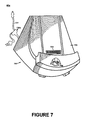
- FIG. 7 is a front perspective view of a palmtop computer docking system that includes a cable assembly that is engaged with a base in accordance with an embodiment of the present invention.
- FIG. 8 illustrates a cut-away side view of the docking cradle of FIG. 7 once the cable assembly is removed therefrom in accordance with one embodiment of the present invention.
- FIG. 9 illustrates a rear view of the docking cradle of FIG. 7 once the cable assembly is removed therefrom in accordance with one embodiment of the present invention.
- FIG. 10 is a front perspective view of a cable assembly that includes a USB connection mechanism in accordance with an embodiment of the present invention.
- FIG. 11 illustrates a side view of a palmtop computer system that is inserted into a palmtop computer docking system in accordance with an embodiment of the present invention.
- FIG. 12 is a front perspective view of a cable assembly that includes a standard serial connector in accordance with an embodiment of the present invention.
- FIG. 1 illustrates a system 50 that includes a palmtop computer docking system 60 .
- System 50 includes a computer system 56 that can either be a desktop unit as shown, or, alternatively, can be a portable computer system such as laptop computer system 58 .
- Computer system 58 and computer system 56 are shown connected to a communication bus 54 , which in one embodiment can be a serial communication bus, but could be of any of a number of well known designs, e.g., a parallel bus, Ethernet Local Area Network (LAN), etc.
- bus 54 can provide communication with the Internet 52 using a number of well-known protocols.
- Bus 54 is also coupled to palmtop computer docking system 60 for receiving and initiating communication with a palmtop (“palm-sized”) portable computer system 100 of the present invention.
- Palmtop computer docking system 60 provides an electrical and mechanical communication interface between bus 54 (and anything coupled to bus 54 ) and computer system 100 for two-way communications.
- Computer system 100 also contains a wireless infrared communication mechanism 64 for sending and receiving information from other devices.
- FIG. 2 is a perspective illustration of an exemplary palmtop computer system 100 .
- Palmtop computer system 100 contains a display screen 105 surrounded by a bezel or cover.
- a removable stylus 80 is also shown.
- the display screen 105 is a touch screen able to register contact between the screen and the tip of the stylus 80 .
- the stylus 80 can be of any material to make contact with the screen 105 .
- Palmtop computing system 100 also contains one or more dedicated and/or programmable buttons 75 for selecting information and causing the computer system to implement functions.
- the on/off button 95 is also shown.
- FIG. 2 also illustrates a handwriting recognition pad or “digitizer” containing two regions 106 a and 106 b .
- Region 106 a is for the drawing of alpha characters therein for automatic recognition and region 106 b is for the drawing of numeric characters therein for automatic recognition.
- the stylus 80 is used for stroking a character within one of the regions 106 a and 106 b .
- the stroke information is then fed to an internal processor for automatic character recognition. Once characters are recognized, they are typically displayed on the screen 105 for verification and/or modification.
- FIG. 3 illustrates the bottom side of palmtop computer system 100 .
- An optional extendible antenna 85 is shown and also a battery storage compartment door 90 is shown.
- a communication interface 108 is also shown.
- the communication interface 108 is a wipe-style serial connector.
- communication interface 108 could be of any of a number of well known types of communication devices and could use any of a number of standards and protocols such as, for example, parallel, SCSI, Firewire (IEEE 1394), Ethernet, etc.
- FIG. 4 is an exploded view of palmtop computer system 100 in accordance with one implementation.
- System 100 contains a front cover 210 having an outline of region 106 and holes 75 a for receiving buttons 75 b .
- a flat panel display 105 (both liquid crystal display and touch screen) fits into front cover 210 . Any of a number of display technologies can be used, e.g., LCD, FED, plasma, etc., for the flat panel display 105 .
- a battery 215 provides electrical power and can be rechargeable.
- a contrast adjustment (potentiometer) 220 is also shown.
- On/off button 95 is shown along with an infrared emitter and detector device 64 .
- a flex circuit 230 is shown along with a PC board 225 containing electronics and logic (e.g., memory, communication bus, processor, etc.) for implementing computer system functionality.
- the digitizer pad is also included in PC board 225 .
- a midframe 235 is shown along with stylus 80 .
- Position adjustable antenna 85 is shown.
- a radio receiver/transmitter device 240 is also shown between the midframe and the rear cover 245 of FIG. 4 .
- the receiver/transmitter device 240 is coupled to the antenna 85 and also coupled to communicate with the PC board 225 .
- FIG. 5 illustrates circuitry of computer system 110 , some of which can be implemented on PC board 225 .
- Computer system 110 includes an address/data bus 109 for communicating information, a central processor 101 coupled with the bus for processing information and instructions, a volatile memory 102 (e.g., random access memory RAM) coupled with the bus 109 for storing information and instructions for the central processor 101 and a non-volatile memory 103 (e.g., read only memory ROM) coupled with the bus 109 for storing static information and instructions for the processor 101 .
- Computer system 110 also includes an optional data storage device 104 (e.g., memory stick) coupled with the bus 109 for storing information and instructions. Device 104 can be removable.
- system 110 also contains a display device 105 coupled to the bus 109 for displaying information to the computer user.
- PC board 225 can contain the processor 101 , the bus 109 , the ROM 103 and the RAM 102 .
- an optional alphanumeric input device 106 that in one implementation is a handwriting recognition pad (“digitizer”) having regions 106 a and 106 b ( FIG. 2A ), for instance.
- Device 106 can communicate information and command selections to the central processor 101 .
- System 110 also includes an optional cursor control or directing device 107 coupled to the bus for communicating user input information and command selections to the central processor 101 .
- device 107 is a touch screen device incorporated with screen 105 . Device 107 is capable of registering a position on the screen 105 where the stylus makes contact.
- the display device 105 utilized with the computer system 100 may be a liquid crystal device, cathode ray tube (CRT), field emission device (FED, also called flat panel CRT) or other display device suitable for creating graphic images and alphanumeric characters recognizable to the user.
- display 105 is a flat panel display.
- Signal input output communication device 108 can be a communication device for communicating with palmtop computer docking system 60 of the present invention.
- communication device 108 is a serial port adapted to couple communications to palmtop computer docking system 60 of the present invention.
- FIG. 6 is a front view of palmtop computer system 100 with a menu bar 305 open displaying a pull down window. Also shown are two regions of digitizer 106 a and 106 b . Region 106 a is for receiving user stroke data for alphabet characters, and typically not numeric characters, and region 106 b is for receiving user stroke data for numeric data, and typically not for alphabetic characters. Physical buttons 75 are also shown.
- FIGS. 7-13 show a palmtop computer docking system 60 a that includes cable assembly 720 a that is adapted to couple a computer system (e.g. palmtop computer system 100 of FIGS. 1-6 and computer system 110 of FIG. 5 ) to other computing systems and/or devices.
- Palmtop computer docking system 60 a also includes base 700 that receives cable assembly 720 a so as to produce a fully functional docking cradle.
- Base 700 includes housing 703 within which button 702 is disposed.
- housing 703 is a molded plastic. However, any of a number of other materials could be used to form housing 703 .
- Palmtop computer connection mechanism 701 couples to base 700 and is adapted to couple to a corresponding connection mechanism (e.g., wipe-style serial connector 108 of FIG. 3 ) on palmtop computer 100 .
- FIGS. 8-9 show base 700 with cable assembly 720 a removed therefrom.
- opening 704 extends through the back surface of housing 703 .
- Connection mechanism 705 is disposed inside of housing 703 proximate to opening 704 .
- Connection mechanism 705 is electrically coupled to connection mechanism 701 and to button 702 .
- connection mechanism 705 is a wipe-style electrical connector that is adapted to receive a palmtop computer connection mechanism.
- cable assembly 720 a includes palmtop computer connection mechanism 724 that is electrically coupled to Universal Serial Bus (USB) connection mechanism 722 via electrical cable 721 .
- connection mechanism 724 is a mechanical and electrical interface for interfacing with palmtop computer system 100 shown in FIGS. 1-6 .
- palmtop computer connection mechanism 724 is a connector receptacle adapted to couple to the wipe-style connector pins of communications interface 108 shown in FIG. 3 .
- USB connection mechanism 722 is a male USB connector adapted to electrically couple cable assembly 720 a to other electrical devices such as, for example, laptop computer 58 and desktop computer 56 of FIG. 1 .
- palmtop computer connection mechanism 724 and palmtop computer connection mechanism 701 of FIGS. 7-8 are wipe-style serial connectors that include engaging projections 732 and electrical contacts 734 for mechanically and electrically engaging to a corresponding connector of a palmtop computer system and mechanically and electrically engaging connection mechanism 705 .
- Cable assembly 720 a also includes power connection mechanism 723 which is adapted to receive power from a power source independent of USB connection mechanism 722 .
- power connection mechanism 723 includes a barrel-style connector receptacle 735 that is disposed within a housing. Connector receptacle 735 is electrically coupled to connector 724 via cable 721 .
- power coupled to power connection mechanism 723 is provided to a palmtop computer, either directly (by coupling the palmtop computer to palmtop computer connection mechanism 734 ) or indirectly (by coupling the palmtop computer to base 700 of FIGS. 7-9 and coupling cable assembly 720 a to base 700 ). Because cable assembly 720 a receives power from a power source independent of USB connector 722 , there is sufficient power to quickly charge a palmtop computer.
- power cable assembly 732 is shown that provides power to connector 735 .
- power cable assembly 730 includes male barrel-style connector 734 , electrical cable 731 , A/C adapter 732 , and electrical plug 733 .
- Electrical plug 733 couples to an electrical outlet for receiving electrical power which is converted from alternating current to direct current at NC adapter 732 and which is transmitted through electrical cable 731 to connector 734 .
- a complete docking cradle is formed.
- the resulting docking cradle is well suited for desktop computing such as, for example, making a connection between the palmtop computing device 100 and a full size computer.
- cable assembly 720 a can be used independently of base 700 for mobile computing applications.
- FIG. 11 shows a palmtop computer 100 disposed within the palmtop computer docking system 60 a formed by coupling cable assembly 720 a to base 700 .
- palmtop computer connection mechanism 724 When palmtop computer connection mechanism 724 is inserted into opening 704 of FIGS. 8-9 , palmtop computer connection mechanism 724 electrically and mechanically connected to base 700 .
- button 702 can be pressed to achieve synchronization with palmtop computer 100 .
- computing devices that are coupled to USB connection mechanism 722 are electrically coupled to palmtop computer system 100 .
- a cable assembly 720 b that includes a serial connector 740 that is adapted to couple to a serial port of a computing device.
- Cable assembly 720 b can couple to base 700 for coupling a palmtop computer to a portable computer or a desktop computer that includes a serial port.
- Cable assembly 720 b can also be used to directly couple a palmtop computer to a portable computer or a desktop computer.
- the present invention is also well adapted to the use of other types of connection mechanisms for coupling to a portable computer or a desktop computer.
- Cable assembly 720 a and cable assembly 720 b are shown to include provision for coupling to a power source that includes an electrical cable 736 , A/C adapter 732 , connector 734 and electrical plug 733 , the present invention is well adapted for use of other mechanisms for coupling to a power source. More particularly, in an alternate embodiment of the present invention (not shown), a cable is used that includes a connector adapted to couple to a direct current power source (e.g., a car cigarette lighter).
- a direct current power source e.g., a car cigarette lighter
- customers are provided with base 700 , cable assembly 720 a , and cable assembly 720 b . This allows for connection to either a USB port or a serial port.
- Cable assembly 720 a and cable assembly 720 b can be used independently of base 700 for coupling to a computer that is a portable computer (e.g. laptop computer 58 of FIG. 1 ) for mobile computing applications. That is, either cable assembly 720 a or cable assembly 720 b is used independently of base 700 to couple to, for example, laptop computer 58 . This is accomplished by connecting palmtop computer connection mechanism 724 directly to a palmtop computer system 100 and connecting the opposite end of cable assembly 720 a or 720 b to the portable computer. Cable assemblies 720 a - 720 b enable mobile users to easily synchronize data between palmtop computer system 100 and laptop computer 58 by operating the laptop computer so as to initiate synchronization.
- a portable computer e.g. laptop computer 58 of FIG. 1
- Cable assemblies 720 a - 720 b are smaller in size and lighter than a full-size conventional docking cradles, and therefore, are more easily carried. Thus, cable assemblies 720 a - 720 b , used independently of base 700 , facilitate mobile computing.
- the palmtop computer docking system 60 a of the present invention is suitable for both a desktop environment (e.g. use with full-size computer 56 of FIG. 1 ) and mobile computing (e.g. laptop computer 58 of FIG. 1 ). More particularly, connection to a portable computer is easily achieved using cable assembly 720 a or cable assembly 720 b while connection to a desktop computer is facilitated by the use of both base 700 and one of cable assemblies 720 a - 720 b.
- Cable assemblies 720 a - 720 b provide electrical power to a palmtop computer, either directly or by use of both a cable assembly and base 700 . This allows for quickly charging the connected palmtop computer.
Abstract
Description
Claims (20)
Priority Applications (1)
| Application Number | Priority Date | Filing Date | Title |
|---|---|---|---|
| US10/222,123 US7976337B1 (en) | 2001-03-07 | 2002-08-16 | Palmtop computer docking system with USB cable assembly |
Applications Claiming Priority (2)
| Application Number | Priority Date | Filing Date | Title |
|---|---|---|---|
| US80199101A | 2001-03-07 | 2001-03-07 | |
| US10/222,123 US7976337B1 (en) | 2001-03-07 | 2002-08-16 | Palmtop computer docking system with USB cable assembly |
Related Parent Applications (1)
| Application Number | Title | Priority Date | Filing Date |
|---|---|---|---|
| US80199101A Division | 2001-03-07 | 2001-03-07 |
Publications (1)
| Publication Number | Publication Date |
|---|---|
| US7976337B1 true US7976337B1 (en) | 2011-07-12 |
Family
ID=44245477
Family Applications (1)
| Application Number | Title | Priority Date | Filing Date |
|---|---|---|---|
| US10/222,123 Expired - Fee Related US7976337B1 (en) | 2001-03-07 | 2002-08-16 | Palmtop computer docking system with USB cable assembly |
Country Status (1)
| Country | Link |
|---|---|
| US (1) | US7976337B1 (en) |
Cited By (16)
| Publication number | Priority date | Publication date | Assignee | Title |
|---|---|---|---|---|
| US20120203949A1 (en) * | 2011-02-03 | 2012-08-09 | Targus Group International, Inc. | Portable electronic device docking station |
| WO2014074989A1 (en) * | 2012-11-12 | 2014-05-15 | Belkin International Inc. | Cable dock assembly and method of manufacturing the same |
| US9330046B2 (en) | 2013-01-14 | 2016-05-03 | Welch Allyn, Inc. | Portable instrument and docking station with divided universal serial bus communication device |
| US9900420B2 (en) | 2014-12-15 | 2018-02-20 | Targus International Llc | Power and data adapter |
| US9904323B2 (en) | 2014-10-28 | 2018-02-27 | Targus International Llc | Power and data adapter, and related systems and methods |
| US10033143B1 (en) * | 2016-09-27 | 2018-07-24 | J28 Design, Inc. | Mirror tap power cord kit |
| US10578657B2 (en) | 2017-07-20 | 2020-03-03 | Targus International Llc | Systems, methods and devices for remote power management and discovery |
| WO2020117204A1 (en) * | 2018-12-04 | 2020-06-11 | Hewlett-Packard Development Company, L.P. | Connector cables to transmit data and power |
| US10705566B2 (en) | 2016-09-09 | 2020-07-07 | Targus International Llc | Systems, methods and devices for native and virtualized video in a hybrid docking station |
| US11017334B2 (en) | 2019-01-04 | 2021-05-25 | Targus International Llc | Workspace management system utilizing smart docking station for monitoring power consumption, occupancy, and usage displayed via heat maps |
| US11039105B2 (en) | 2019-08-22 | 2021-06-15 | Targus International Llc | Systems and methods for participant-controlled video conferencing |
| US11075492B2 (en) * | 2018-11-06 | 2021-07-27 | Samsung Electronics Co., Ltd. | Adapter and electronic system having the same |
| US11231448B2 (en) | 2017-07-20 | 2022-01-25 | Targus International Llc | Systems, methods and devices for remote power management and discovery |
| US11360534B2 (en) | 2019-01-04 | 2022-06-14 | Targus Internatonal Llc | Smart workspace management system |
| US11614776B2 (en) | 2019-09-09 | 2023-03-28 | Targus International Llc | Systems and methods for docking stations removably attachable to display apparatuses |
| US11740657B2 (en) | 2018-12-19 | 2023-08-29 | Targus International Llc | Display and docking apparatus for a portable electronic device |
Citations (16)
| Publication number | Priority date | Publication date | Assignee | Title |
|---|---|---|---|---|
| DE9409902U1 (en) | 1994-06-18 | 1994-09-01 | Velan Telekommunikation Car Hi | Device for holding and charging hand-held radio telephones in motor vehicles or the like. |
| US5573425A (en) * | 1993-10-18 | 1996-11-12 | Asahi Kogaku Kogyo Kabushiki Kaisha | Communication cable used in a computer system |
| US5982614A (en) * | 1996-11-18 | 1999-11-09 | Peripheral Vision, Inc. | Docking station including a port replicator for sharing peripherals between a portable computer and desktop computer |
| DE29917189U1 (en) | 1999-09-30 | 2000-01-13 | Techart Carconsolen Gmbh | Mobile phone holder in a vehicle |
| USD420989S (en) * | 1998-03-09 | 2000-02-22 | 3Com Corporation | Cradle for a handheld computer |
| US6152778A (en) * | 1998-02-26 | 2000-11-28 | Hewlett-Packard Company | Electronic connector adapter with power input |
| US6154010A (en) * | 1998-11-19 | 2000-11-28 | Microsoft Corporation | Battery charging docking cradle for a mobile computer |
| US6208734B1 (en) | 1996-12-18 | 2001-03-27 | Nokia Mobile Phones Limited | Holding device for a communications unit |
| US6240426B1 (en) * | 1998-11-18 | 2001-05-29 | Siemens Information & Communication Networks, Inc. | Method and apparatus for synchronizing information between a mobile device and a data collection device through a telephone switching network |
| US6283789B1 (en) * | 2000-03-16 | 2001-09-04 | Shui Chuan Tsai | Data and power transmitting cable system |
| US6283777B1 (en) * | 1999-05-26 | 2001-09-04 | Palm, Inc. | Dual style connector for handheld computer |
| US6364697B1 (en) * | 2000-05-12 | 2002-04-02 | Palm, Inc. | Palmtop computer docking system |
| USD458266S1 (en) * | 2001-03-21 | 2002-06-04 | Vianix, Lc | Cradle for a handheld device |
| US6483698B1 (en) * | 1998-11-27 | 2002-11-19 | Hewlett-Packard Company | Cradle for supporting a PDA and similar portable electronic devices |
| US6608264B1 (en) * | 2002-03-29 | 2003-08-19 | Afshin Fouladpour | Switchable data and power cable |
| US6909907B1 (en) * | 2000-11-10 | 2005-06-21 | Pharos Science & Applications, Inc. | Integrated connection assembly for global positioning system (GPS) receiver and personal digital assistance (PDA) device or cellular phones |
-
2002
- 2002-08-16 US US10/222,123 patent/US7976337B1/en not_active Expired - Fee Related
Patent Citations (16)
| Publication number | Priority date | Publication date | Assignee | Title |
|---|---|---|---|---|
| US5573425A (en) * | 1993-10-18 | 1996-11-12 | Asahi Kogaku Kogyo Kabushiki Kaisha | Communication cable used in a computer system |
| DE9409902U1 (en) | 1994-06-18 | 1994-09-01 | Velan Telekommunikation Car Hi | Device for holding and charging hand-held radio telephones in motor vehicles or the like. |
| US5982614A (en) * | 1996-11-18 | 1999-11-09 | Peripheral Vision, Inc. | Docking station including a port replicator for sharing peripherals between a portable computer and desktop computer |
| US6208734B1 (en) | 1996-12-18 | 2001-03-27 | Nokia Mobile Phones Limited | Holding device for a communications unit |
| US6152778A (en) * | 1998-02-26 | 2000-11-28 | Hewlett-Packard Company | Electronic connector adapter with power input |
| USD420989S (en) * | 1998-03-09 | 2000-02-22 | 3Com Corporation | Cradle for a handheld computer |
| US6240426B1 (en) * | 1998-11-18 | 2001-05-29 | Siemens Information & Communication Networks, Inc. | Method and apparatus for synchronizing information between a mobile device and a data collection device through a telephone switching network |
| US6154010A (en) * | 1998-11-19 | 2000-11-28 | Microsoft Corporation | Battery charging docking cradle for a mobile computer |
| US6483698B1 (en) * | 1998-11-27 | 2002-11-19 | Hewlett-Packard Company | Cradle for supporting a PDA and similar portable electronic devices |
| US6283777B1 (en) * | 1999-05-26 | 2001-09-04 | Palm, Inc. | Dual style connector for handheld computer |
| DE29917189U1 (en) | 1999-09-30 | 2000-01-13 | Techart Carconsolen Gmbh | Mobile phone holder in a vehicle |
| US6283789B1 (en) * | 2000-03-16 | 2001-09-04 | Shui Chuan Tsai | Data and power transmitting cable system |
| US6364697B1 (en) * | 2000-05-12 | 2002-04-02 | Palm, Inc. | Palmtop computer docking system |
| US6909907B1 (en) * | 2000-11-10 | 2005-06-21 | Pharos Science & Applications, Inc. | Integrated connection assembly for global positioning system (GPS) receiver and personal digital assistance (PDA) device or cellular phones |
| USD458266S1 (en) * | 2001-03-21 | 2002-06-04 | Vianix, Lc | Cradle for a handheld device |
| US6608264B1 (en) * | 2002-03-29 | 2003-08-19 | Afshin Fouladpour | Switchable data and power cable |
Cited By (24)
| Publication number | Priority date | Publication date | Assignee | Title |
|---|---|---|---|---|
| US8990469B2 (en) * | 2011-02-03 | 2015-03-24 | Targus Group International, Inc. | Portable electronic device docking station |
| US20120203949A1 (en) * | 2011-02-03 | 2012-08-09 | Targus Group International, Inc. | Portable electronic device docking station |
| WO2014074989A1 (en) * | 2012-11-12 | 2014-05-15 | Belkin International Inc. | Cable dock assembly and method of manufacturing the same |
| US10061739B2 (en) | 2013-01-14 | 2018-08-28 | Welch Allyn, Inc. | Portable instrument and docking station with divided universal serial bus communication device |
| US9330046B2 (en) | 2013-01-14 | 2016-05-03 | Welch Allyn, Inc. | Portable instrument and docking station with divided universal serial bus communication device |
| US9904323B2 (en) | 2014-10-28 | 2018-02-27 | Targus International Llc | Power and data adapter, and related systems and methods |
| US9900420B2 (en) | 2014-12-15 | 2018-02-20 | Targus International Llc | Power and data adapter |
| US10705566B2 (en) | 2016-09-09 | 2020-07-07 | Targus International Llc | Systems, methods and devices for native and virtualized video in a hybrid docking station |
| US11567537B2 (en) | 2016-09-09 | 2023-01-31 | Targus International Llc | Systems, methods and devices for native and virtualized video in a hybrid docking station |
| US11023008B2 (en) | 2016-09-09 | 2021-06-01 | Targus International Llc | Systems, methods and devices for native and virtualized video in a hybrid docking station |
| US10033143B1 (en) * | 2016-09-27 | 2018-07-24 | J28 Design, Inc. | Mirror tap power cord kit |
| US10578657B2 (en) | 2017-07-20 | 2020-03-03 | Targus International Llc | Systems, methods and devices for remote power management and discovery |
| US10663498B2 (en) | 2017-07-20 | 2020-05-26 | Targus International Llc | Systems, methods and devices for remote power management and discovery |
| US11747375B2 (en) | 2017-07-20 | 2023-09-05 | Targus International Llc | Systems, methods and devices for remote power management and discovery |
| US11231448B2 (en) | 2017-07-20 | 2022-01-25 | Targus International Llc | Systems, methods and devices for remote power management and discovery |
| US11075492B2 (en) * | 2018-11-06 | 2021-07-27 | Samsung Electronics Co., Ltd. | Adapter and electronic system having the same |
| WO2020117204A1 (en) * | 2018-12-04 | 2020-06-11 | Hewlett-Packard Development Company, L.P. | Connector cables to transmit data and power |
| US11740657B2 (en) | 2018-12-19 | 2023-08-29 | Targus International Llc | Display and docking apparatus for a portable electronic device |
| US11017334B2 (en) | 2019-01-04 | 2021-05-25 | Targus International Llc | Workspace management system utilizing smart docking station for monitoring power consumption, occupancy, and usage displayed via heat maps |
| US11360534B2 (en) | 2019-01-04 | 2022-06-14 | Targus Internatonal Llc | Smart workspace management system |
| US11405588B2 (en) | 2019-08-22 | 2022-08-02 | Targus International Llc | Systems and methods for participant-controlled video conferencing |
| US11039105B2 (en) | 2019-08-22 | 2021-06-15 | Targus International Llc | Systems and methods for participant-controlled video conferencing |
| US11818504B2 (en) | 2019-08-22 | 2023-11-14 | Targus International Llc | Systems and methods for participant-controlled video conferencing |
| US11614776B2 (en) | 2019-09-09 | 2023-03-28 | Targus International Llc | Systems and methods for docking stations removably attachable to display apparatuses |
Similar Documents
| Publication | Publication Date | Title |
|---|---|---|
| US6364697B1 (en) | Palmtop computer docking system | |
| US7976337B1 (en) | Palmtop computer docking system with USB cable assembly | |
| US6519144B1 (en) | Wall mount cradle for personal digital assistants | |
| US8261109B2 (en) | Power sharing between portable computer system and peripheral devices | |
| US6545862B1 (en) | Method and system for an interchangeable modular display screen for a portable computing device | |
| US7242963B1 (en) | System and method for using a wireless enabled portable computer system as a wireless modem | |
| US8654086B2 (en) | Method and system for changing the power state of a portable electronic device | |
| US7610068B2 (en) | Radio modem terminal for mobile communication | |
| US8031212B2 (en) | Reorienting display on portable computing device | |
| US20030021082A1 (en) | Detachable wireless input device of notebook computer | |
| US7249325B1 (en) | Automatically centered scrolling in a tab-based user interface | |
| US7733637B1 (en) | Keyboard sled with rotating screen | |
| TWI594128B (en) | Intelligent platform with an exchangeable intelligent core | |
| US6618044B1 (en) | Selectively relocatable and universal interface module with circuitry for a display screen | |
| USRE43862E1 (en) | Palmtop computer expansion using shaped memory access | |
| JPH09101842A (en) | Portable electronic equipment | |
| US20080016250A1 (en) | Method and system for device bootstrapping via server synchronization | |
| US6381126B1 (en) | Cover with viewing window for palmtop computer | |
| US7066392B1 (en) | Multimedia connector reader device | |
| US20020178343A1 (en) | Personal digital assistant for connecting with a digital image capture device | |
| JP2004147272A (en) | Communication module for cellular phone and mobile pc with wireless mouse and ten key functions of which main body can be bisected | |
| US6810450B2 (en) | Personal digital assistant system | |
| US20060126286A1 (en) | Mouse and portable computer with the same | |
| CN214011840U (en) | Portable server maintenance device with KVM function | |
| CN218383907U (en) | Bluetooth input device integrated with docking station function |
Legal Events
| Date | Code | Title | Description |
|---|---|---|---|
| AS | Assignment |
Owner name: JP MORGAN CHASE BANK, N.A., AS ADMINISTRATIVE AGEN Free format text: SECURITY AGREEMENT;ASSIGNOR:PALM, INC.;REEL/FRAME:020113/0429 Effective date: 20071024 |
|
| AS | Assignment |
Owner name: PALM, INC., CALIFORNIA Free format text: RELEASE BY SECURED PARTY;ASSIGNOR:JPMORGAN CHASE BANK, N.A., AS ADMINISTRATIVE AGENT;REEL/FRAME:024630/0474 Effective date: 20100701 |
|
| AS | Assignment |
Owner name: HEWLETT-PACKARD DEVELOPMENT COMPANY, L.P., TEXAS Free format text: ASSIGNMENT OF ASSIGNORS INTEREST;ASSIGNOR:PALM, INC.;REEL/FRAME:025204/0809 Effective date: 20101027 |
|
| STCF | Information on status: patent grant |
Free format text: PATENTED CASE |
|
| AS | Assignment |
Owner name: PALM, INC., CALIFORNIA Free format text: ASSIGNMENT OF ASSIGNORS INTEREST;ASSIGNOR:HEWLETT-PACKARD DEVELOPMENT COMPANY, L.P.;REEL/FRAME:030341/0459 Effective date: 20130430 |
|
| AS | Assignment |
Owner name: HEWLETT-PACKARD DEVELOPMENT COMPANY, L.P., TEXAS Free format text: ASSIGNMENT OF ASSIGNORS INTEREST;ASSIGNOR:PALM, INC.;REEL/FRAME:031837/0239 Effective date: 20131218 Owner name: HEWLETT-PACKARD DEVELOPMENT COMPANY, L.P., TEXAS Free format text: ASSIGNMENT OF ASSIGNORS INTEREST;ASSIGNOR:PALM, INC.;REEL/FRAME:031837/0659 Effective date: 20131218 Owner name: PALM, INC., CALIFORNIA Free format text: ASSIGNMENT OF ASSIGNORS INTEREST;ASSIGNOR:HEWLETT-PACKARD DEVELOPMENT COMPANY, L.P.;REEL/FRAME:031837/0544 Effective date: 20131218 |
|
| AS | Assignment |
Owner name: QUALCOMM INCORPORATED, CALIFORNIA Free format text: ASSIGNMENT OF ASSIGNORS INTEREST;ASSIGNORS:HEWLETT-PACKARD COMPANY;HEWLETT-PACKARD DEVELOPMENT COMPANY, L.P.;PALM, INC.;REEL/FRAME:032177/0210 Effective date: 20140123 |
|
| FPAY | Fee payment |
Year of fee payment: 4 |
|
| MAFP | Maintenance fee payment |
Free format text: PAYMENT OF MAINTENANCE FEE, 8TH YEAR, LARGE ENTITY (ORIGINAL EVENT CODE: M1552); ENTITY STATUS OF PATENT OWNER: LARGE ENTITY Year of fee payment: 8 |
|
| FEPP | Fee payment procedure |
Free format text: MAINTENANCE FEE REMINDER MAILED (ORIGINAL EVENT CODE: REM.); ENTITY STATUS OF PATENT OWNER: LARGE ENTITY |
|
| LAPS | Lapse for failure to pay maintenance fees |
Free format text: PATENT EXPIRED FOR FAILURE TO PAY MAINTENANCE FEES (ORIGINAL EVENT CODE: EXP.); ENTITY STATUS OF PATENT OWNER: LARGE ENTITY |
|
| STCH | Information on status: patent discontinuation |
Free format text: PATENT EXPIRED DUE TO NONPAYMENT OF MAINTENANCE FEES UNDER 37 CFR 1.362 |
|
| FP | Lapsed due to failure to pay maintenance fee |
Effective date: 20230712 |