US7980952B2 - Storage medium having information processing program stored thereon and information processing apparatus - Google Patents
Storage medium having information processing program stored thereon and information processing apparatus Download PDFInfo
- Publication number
- US7980952B2 US7980952B2 US11/889,246 US88924607A US7980952B2 US 7980952 B2 US7980952 B2 US 7980952B2 US 88924607 A US88924607 A US 88924607A US 7980952 B2 US7980952 B2 US 7980952B2
- Authority
- US
- United States
- Prior art keywords
- vector
- acceleration
- calculated
- accumulation
- data
- Prior art date
- Legal status (The legal status is an assumption and is not a legal conclusion. Google has not performed a legal analysis and makes no representation as to the accuracy of the status listed.)
- Active, expires
Links
- 230000010365 information processing Effects 0.000 title claims description 61
- 230000001133 acceleration Effects 0.000 claims abstract description 595
- 239000013598 vector Substances 0.000 claims abstract description 446
- 238000009825 accumulation Methods 0.000 claims abstract description 194
- 238000012545 processing Methods 0.000 claims abstract description 60
- 238000000034 method Methods 0.000 claims description 154
- 230000008569 process Effects 0.000 claims description 136
- 230000008859 change Effects 0.000 claims description 118
- 238000003825 pressing Methods 0.000 claims description 8
- 230000033001 locomotion Effects 0.000 description 50
- 230000015654 memory Effects 0.000 description 49
- 230000003068 static effect Effects 0.000 description 24
- 238000004891 communication Methods 0.000 description 21
- 238000010586 diagram Methods 0.000 description 18
- 238000003384 imaging method Methods 0.000 description 18
- 239000000758 substrate Substances 0.000 description 16
- 230000003287 optical effect Effects 0.000 description 15
- 230000005540 biological transmission Effects 0.000 description 13
- 230000006870 function Effects 0.000 description 12
- 238000005259 measurement Methods 0.000 description 12
- 238000001514 detection method Methods 0.000 description 8
- 238000011112 process operation Methods 0.000 description 8
- 238000005516 engineering process Methods 0.000 description 6
- 230000004044 response Effects 0.000 description 6
- 230000002238 attenuated effect Effects 0.000 description 5
- 230000005484 gravity Effects 0.000 description 5
- 230000003466 anti-cipated effect Effects 0.000 description 4
- 230000004043 responsiveness Effects 0.000 description 4
- CZZAPCPWFCGOCC-GHXNOFRVSA-N (5z)-2-amino-5-[[5-(2-nitrophenyl)furan-2-yl]methylidene]-1,3-thiazol-4-one Chemical compound S1C(N)=NC(=O)\C1=C\C1=CC=C(C=2C(=CC=CC=2)[N+]([O-])=O)O1 CZZAPCPWFCGOCC-GHXNOFRVSA-N 0.000 description 2
- 230000009471 action Effects 0.000 description 2
- 230000003139 buffering effect Effects 0.000 description 2
- 239000000919 ceramic Substances 0.000 description 2
- 239000002131 composite material Substances 0.000 description 2
- 230000003111 delayed effect Effects 0.000 description 2
- 238000009499 grossing Methods 0.000 description 2
- 238000010137 moulding (plastic) Methods 0.000 description 2
- 230000002441 reversible effect Effects 0.000 description 2
- 230000005236 sound signal Effects 0.000 description 2
- XUIMIQQOPSSXEZ-UHFFFAOYSA-N Silicon Chemical compound [Si] XUIMIQQOPSSXEZ-UHFFFAOYSA-N 0.000 description 1
- 238000010168 coupling process Methods 0.000 description 1
- 238000005859 coupling reaction Methods 0.000 description 1
- 238000006073 displacement reaction Methods 0.000 description 1
- 230000000694 effects Effects 0.000 description 1
- 230000002708 enhancing effect Effects 0.000 description 1
- 230000010354 integration Effects 0.000 description 1
- 238000012986 modification Methods 0.000 description 1
- 230000004048 modification Effects 0.000 description 1
- 230000002093 peripheral effect Effects 0.000 description 1
- 239000010453 quartz Substances 0.000 description 1
- 238000009877 rendering Methods 0.000 description 1
- 238000005070 sampling Methods 0.000 description 1
- 239000004065 semiconductor Substances 0.000 description 1
- 229910052710 silicon Inorganic materials 0.000 description 1
- 239000010703 silicon Substances 0.000 description 1
- VYPSYNLAJGMNEJ-UHFFFAOYSA-N silicon dioxide Inorganic materials O=[Si]=O VYPSYNLAJGMNEJ-UHFFFAOYSA-N 0.000 description 1
- 239000007787 solid Substances 0.000 description 1
Images


Classifications
-
- A—HUMAN NECESSITIES
- A63—SPORTS; GAMES; AMUSEMENTS
- A63F—CARD, BOARD, OR ROULETTE GAMES; INDOOR GAMES USING SMALL MOVING PLAYING BODIES; VIDEO GAMES; GAMES NOT OTHERWISE PROVIDED FOR
- A63F13/00—Video games, i.e. games using an electronically generated display having two or more dimensions
- A63F13/40—Processing input control signals of video game devices, e.g. signals generated by the player or derived from the environment
- A63F13/42—Processing input control signals of video game devices, e.g. signals generated by the player or derived from the environment by mapping the input signals into game commands, e.g. mapping the displacement of a stylus on a touch screen to the steering angle of a virtual vehicle
- A63F13/428—Processing input control signals of video game devices, e.g. signals generated by the player or derived from the environment by mapping the input signals into game commands, e.g. mapping the displacement of a stylus on a touch screen to the steering angle of a virtual vehicle involving motion or position input signals, e.g. signals representing the rotation of an input controller or a player's arm motions sensed by accelerometers or gyroscopes
-
- A—HUMAN NECESSITIES
- A63—SPORTS; GAMES; AMUSEMENTS
- A63F—CARD, BOARD, OR ROULETTE GAMES; INDOOR GAMES USING SMALL MOVING PLAYING BODIES; VIDEO GAMES; GAMES NOT OTHERWISE PROVIDED FOR
- A63F13/00—Video games, i.e. games using an electronically generated display having two or more dimensions
- A63F13/20—Input arrangements for video game devices
- A63F13/21—Input arrangements for video game devices characterised by their sensors, purposes or types
- A63F13/211—Input arrangements for video game devices characterised by their sensors, purposes or types using inertial sensors, e.g. accelerometers or gyroscopes
-
- G—PHYSICS
- G06—COMPUTING; CALCULATING OR COUNTING
- G06F—ELECTRIC DIGITAL DATA PROCESSING
- G06F3/00—Input arrangements for transferring data to be processed into a form capable of being handled by the computer; Output arrangements for transferring data from processing unit to output unit, e.g. interface arrangements
- G06F3/01—Input arrangements or combined input and output arrangements for interaction between user and computer
- G06F3/03—Arrangements for converting the position or the displacement of a member into a coded form
- G06F3/033—Pointing devices displaced or positioned by the user, e.g. mice, trackballs, pens or joysticks; Accessories therefor
- G06F3/0346—Pointing devices displaced or positioned by the user, e.g. mice, trackballs, pens or joysticks; Accessories therefor with detection of the device orientation or free movement in a 3D space, e.g. 3D mice, 6-DOF [six degrees of freedom] pointers using gyroscopes, accelerometers or tilt-sensors
-
- G—PHYSICS
- G06—COMPUTING; CALCULATING OR COUNTING
- G06F—ELECTRIC DIGITAL DATA PROCESSING
- G06F3/00—Input arrangements for transferring data to be processed into a form capable of being handled by the computer; Output arrangements for transferring data from processing unit to output unit, e.g. interface arrangements
- G06F3/01—Input arrangements or combined input and output arrangements for interaction between user and computer
- G06F3/03—Arrangements for converting the position or the displacement of a member into a coded form
- G06F3/033—Pointing devices displaced or positioned by the user, e.g. mice, trackballs, pens or joysticks; Accessories therefor
- G06F3/038—Control and interface arrangements therefor, e.g. drivers or device-embedded control circuitry
-
- A—HUMAN NECESSITIES
- A63—SPORTS; GAMES; AMUSEMENTS
- A63F—CARD, BOARD, OR ROULETTE GAMES; INDOOR GAMES USING SMALL MOVING PLAYING BODIES; VIDEO GAMES; GAMES NOT OTHERWISE PROVIDED FOR
- A63F2300/00—Features of games using an electronically generated display having two or more dimensions, e.g. on a television screen, showing representations related to the game
- A63F2300/10—Features of games using an electronically generated display having two or more dimensions, e.g. on a television screen, showing representations related to the game characterized by input arrangements for converting player-generated signals into game device control signals
- A63F2300/105—Features of games using an electronically generated display having two or more dimensions, e.g. on a television screen, showing representations related to the game characterized by input arrangements for converting player-generated signals into game device control signals using inertial sensors, e.g. accelerometers, gyroscopes
-
- A—HUMAN NECESSITIES
- A63—SPORTS; GAMES; AMUSEMENTS
- A63F—CARD, BOARD, OR ROULETTE GAMES; INDOOR GAMES USING SMALL MOVING PLAYING BODIES; VIDEO GAMES; GAMES NOT OTHERWISE PROVIDED FOR
- A63F2300/00—Features of games using an electronically generated display having two or more dimensions, e.g. on a television screen, showing representations related to the game
- A63F2300/60—Methods for processing data by generating or executing the game program
- A63F2300/6045—Methods for processing data by generating or executing the game program for mapping control signals received from the input arrangement into game commands
Definitions
- the technology herein relates to a storage medium having an information processing program stored thereon and an information processing apparatus, and more particularly to an information processing apparatus for detecting for an acceleration applied to a housing of a controller so as to perform an operation, and a storage medium having stored thereon an information processing program executed by the apparatus.
- Patent Document 1 Japanese Laid-Open Patent Publication No. 6-50758 discloses an information processing apparatus which uses a remote commander (input device) having a vibrating gyroscope (an angular velocity sensor) mounted therein so as to perform a processing.
- a remote commander input device
- a vibrating gyroscope an angular velocity sensor
- the information processing apparatus disclosed in Patent Document 1 determines a direction in which a user moves the remote commander, based on an angular velocity obtained by the vibrating gyroscope, and executes a command in accordance with the determination result. Specifically, a voltage generated from a driving piezoelectric ceramic included in the vibrating gyroscope rises in accordance with an angular velocity obtained when a user moves the remote commander upward. On the other hand, a voltage generated from the driving piezoelectric ceramic drops in accordance with an angular velocity obtained when a user moves the remote commander downward.
- the information processing apparatus determines that the remote commander is moved upward when the voltage rises up to a predetermined value, whereas the information processing apparatus determines that the remote commander is moved downward when the voltage drops to a predetermined value.
- the information processing apparatus moves a cursor in a display screen upward in accordance with a command to be executed in response to the remote commander being moved upward, whereas the information processing apparatus moves the cursor in the display screen downward in accordance with a command to be executed in response to the remote commander being moved downward.
- the vibrating gyroscope (angular velocity sensor) mounted in the input device disclosed in Patent Document 1 costs more than an acceleration sensor and the like, which leads to increase in cost of the input device itself.
- the vibrating gyroscope is simply replaced with an acceleration sensor so as to mount the acceleration sensor in the input device, and a value of data outputted by the acceleration sensor is used as it is, the gravitational acceleration applied to the input device may be included in the value, whereby an accurate determination becomes difficult.
- an acceleration may be applied to the input device in the direction opposite to the predetermined direction, or the acceleration may be variable depending on an operation performed by a user, or an acceleration may be influenced by an accuracy error of the device itself, for example. In these cases, accurate determination may become difficult.
- certain example embodiments provide a storage medium having stored thereon an information processing program and an information processing apparatus for realizing an accurate operation, in an inexpensive manner, by using data outputted by an acceleration sensor mounted in a predetermined housing.
- a first aspect of certain example embodiments is directed to a storage medium having stored thereon an information processing program executed by a computer ( 10 ) of an information processing apparatus ( 5 ) which performs a processing using acceleration data (accn) outputted by an acceleration sensor ( 701 , 706 ) for detecting for an acceleration, in at least one axial direction, applied to a predetermined housing ( 70 , 71 , 76 , 77 ) thereof.
- the information processing program causes the computer to function as: acceleration data acquisition means (step 43 , the CPU 10 which executes step 103 ; hereinafter, only step numbers will be represented); accumulation vector calculation means (S 48 , S 108 ); following vector calculation means (S 49 , S 109 ); differential vector calculation means (S 50 , S 110 ); and processing means (S 51 , S 113 ).
- the acceleration data acquisition means repeatedly acquires the acceleration data.
- the accumulation vector calculation means calculates an accumulation vector (veca) by sequentially accumulating an acceleration vector having a magnitude and a direction of the acceleration represented by the acceleration data acquired by the acceleration data acquisition means.
- the following vector calculation means calculates a following vector (vecg) which follows, at a predetermined rate (K), the accumulation vector calculated by the accumulation vector calculation means, by using the acceleration data acquired by the acceleration data acquisition means.
- the differential vector calculation means calculates, as a differential vector (vecd), a difference between the accumulation vector and the following vector.
- the processing means designates a position (pos) in a virtual world displayed by a display device ( 2 ) using a value (vecdX, vecdY, vecdZ, daX, daY, daZ) determined in accordance with the differential vector, and performs a predetermined processing by using the position.
- the processing means designates the position, in the virtual world, corresponding to axial component values (vecdX, vecdY, vecdZ) of the differential vector, and performs the predetermined processing using the position.
- the accumulation vector calculation means includes attenuation processing means (S 47 , S 107 ).
- the attenuation processing means sequentially attenuates the accumulation vector before or after the acceleration vector is added to the accumulation vector.
- the processing means designates the position, in the virtual world, corresponding to the axial component values of the differential vector, and performs the predetermined processing by using the position.
- the acceleration sensor is capable of detecting for the acceleration having the magnitude within a predetermined measurable range.
- the information processing program causes the computer to further function as change amount vector calculation means (S 82 , S 86 , S 90 ) and estimated acceleration vector calculation means (S 83 , S 84 , S 87 , S 88 , S 91 , S 92 ).
- the change amount vector calculation means calculates, by using the acceleration data acquired by the acceleration data acquisition means, a change amount vector (accv) representing a change amount of the acceleration, when the magnitude of the acceleration represented by the acceleration data acquired by the acceleration data acquisition means has a value within the predetermined measurable range (Yes in S 81 , S 85 , S 89 ).
- the estimated acceleration vector calculation means calculates, when the magnitude of the acceleration represented by the acceleration data acquired by the acceleration data acquisition means has a value outside the predetermined measurable range (No in S 81 , s 85 , S 89 ), an estimated acceleration vector (accn) by attenuating, by a predetermined amount, the change amount vector immediately preceding the change amount vector being currently calculated so as to update the change amount vector, and adding the updated change amount vector to the acceleration vector having been most recently used by the accumulation vector calculation means.
- the accumulation vector calculation means updates, when the magnitude of the acceleration vector having the magnitude and the direction of the acceleration represented by the acceleration data acquired by the acceleration data acquisition means has a value outside the predetermined measurable range, the accumulation vector by adding the estimated acceleration vector to the accumulation vector.
- the predetermined processing performed by the processing means is a process of positioning a predetermined object (OBJ) at the position having been designated in the virtual world, and moving the predetermined object in the virtual world in accordance with the position being moved.
- OBJ predetermined object
- the processing means designates the position by associating the axial component values of the differential vector with coordinate values of a coordinate system (xyz) defined in the virtual world, respectively.
- the processing means moves, in the virtual world, an originating point (reference position) of the coordinate system defined in the virtual world when a predetermined condition is satisfied.
- the acceleration data acquisition means repeatedly acquires, when an input device ( 7 ) has a first housing and a second housing ( 71 , 77 ), first acceleration data outputted by a first acceleration sensor mounted in the first housing, and second acceleration data outputted by a second acceleration sensor mounted in the second housing.
- the accumulation vector calculation means sequentially accumulates a first acceleration vector having a magnitude and a direction of an acceleration represented by the first acceleration data, so as to calculate a first accumulation vector, and sequentially accumulates a second acceleration vector having a magnitude and a direction of an acceleration represented by the second acceleration data, so as to calculate a second accumulation vector.
- the following vector calculation means calculates a first following vector which follows, at a predetermined rate, the first accumulation vector, by using the first acceleration data, and calculates a second following vector which follows, at a predetermined rate, the second accumulation vector, by using the second acceleration data.
- the differential vector calculation means calculates, as a first differential vector, a difference between the first accumulation vector and the first following vector, and calculates, as a second differential vector, a difference between the second accumulation vector and the second following vector.
- the processing means designates a first position by associating axial component values of the first differential vector with coordinate values of a first coordinate system defined in the virtual world, respectively, and designates a second position by associating axial component values of the second differential vector with coordinate values of a second coordinate system, respectively, which is different from the first coordinate system and defined in the virtual world.
- the predetermined processing performed by the processing means is a process of positioning a first object (OBJ 1 ) at the first position and a second object (OBJ 2 ) at the second position, and moving the first object and the second object in the virtual world in accordance with the first position and the second position being moved, respectively.
- the information processing program causes the computer to further function as accumulation differential value calculation means (S 112 ).
- the accumulation differential value calculation means calculates an accumulation differential value (da) by sequentially accumulating the differential vector calculated by the differential vector calculation means, in units of axial component values thereof.
- the processing means designates the position, in the virtual world, corresponding to the accumulation differential value (daX, daY, daZ) calculated by the accumulation differential value calculation means, and performs the predetermined processing using the position.
- the accumulation vector calculation means includes attenuation processing means.
- the attenuation processing means sequentially attenuates the accumulation vector before or after the acceleration vector is added to the accumulation vector.
- the accumulation differential value calculation means calculates the accumulation differential value by sequentially accumulating the differential vector in units of the axial component values thereof when a magnitude of the differential vector calculated by the differential vector calculation means is larger than a predetermined threshold value.
- the acceleration sensor is capable of detecting for the acceleration having the magnitude within a predetermined measurable range.
- the information processing program causes the computer to further function as change amount vector calculation means and estimated acceleration vector calculation means.
- the change amount vector calculation means calculates, by using the acceleration data acquired by the acceleration data acquisition means, a change amount vector representing a change amount of the acceleration, when the magnitude of the acceleration represented by the acceleration data acquired by the acceleration data acquisition means has a value within the predetermined measurable range.
- the estimated acceleration vector calculation means calculates, when the magnitude of the acceleration represented by the acceleration data acquired by the acceleration data acquisition means has a value outside the predetermined measurable range, an estimated acceleration vector by attenuating, by a predetermined amount, the change amount vector immediately preceding the change amount vector being currently calculated so as to update the change amount vector, and adding the updated change amount vector to the acceleration vector having been most recently used by the accumulation vector calculation means.
- the accumulation vector calculation means updates, when the magnitude of the acceleration vector having the magnitude and the direction of the acceleration represented by the acceleration data acquired by the acceleration data acquisition means has a value outside the predetermined measurable range, the accumulation vector by adding the estimated acceleration vector to the accumulation vector.
- the predetermined processing performed by the processing means is a process of positioning a predetermined object at the position having been designated in the virtual world, and moving the predetermined object in the virtual world in accordance with the position being moved.
- the predetermined housing includes at least one operation button ( 72 ) for outputting predetermined operation data in accordance with a user pressing the at least one operation button.
- the information processing program causes the computer to further function as operation data acquisition means (S 111 ).
- the operation data acquisition means repeatedly acquires the operation data.
- the accumulation differential value calculation means sequentially accumulates the differential vector in units of the axial component values thereof only when the operation data indicating that a predetermined operation button among the at least one operation button is pressed is acquired.
- a fifteenth aspect of certain example embodiments is directed to an information processing apparatus for performing a processing using acceleration data outputted by an acceleration sensor for detecting for an acceleration, in at least one axial direction, applied to a predetermined housing thereof.
- the information processing apparatus comprises: acceleration data acquisition means; accumulation vector calculation means; following vector calculation means; differential vector calculation means; and processing means.
- the acceleration data acquisition means repeatedly acquires the acceleration data.
- the accumulation vector calculation means calculates an accumulation vector by sequentially accumulating an acceleration vector having a magnitude and a direction of the acceleration represented by the acceleration data acquired by the acceleration data acquisition means.
- the following vector calculation means calculates a following vector which follows, at a predetermined rate, the accumulation vector calculated by the accumulation vector calculation means, by using the acceleration data acquired by the acceleration data acquisition means.
- the differential vector calculation means calculates, as a differential vector, a difference between the accumulation vector and the following vector.
- the processing means designates a position in a virtual world displayed by a display device using a value determined in accordance with the differential vector, and performs a predetermined processing by using the position.
- a value for example, the respective axial component values of the differential vector or a value obtained by accumulating the differential vector in units of axial component values thereof
- a value determined in accordance with the differential vector is used as a three-dimensional position in the real space relative to a position at which the housing has started to be moved, so as to designate a position in the virtual world. Therefore, it is possible to accurately designate the position by using an output value from an inexpensive acceleration sensor.
- the respective axial component values of the differential vector are used as the three-dimensional position in the real space relative to a position at which the housing has started to be moved, so as to designate a position in the virtual world. Therefore, it is possible to accurately designate the position by using an output value from an inexpensive acceleration sensor. For example, when a user moves the housing, which has been at rest, in a certain direction and then stops the housing, the differential vector represents this movement and eventually has a value of zero. Therefore, a position obtained by, for example, scaling the respective axial component values of the differential vector in the virtual world so as to designate a coordinate point corresponding to the respective axial component values is moved from the reference position toward the direction in which the housing is moved, and eventually returns to the reference position.
- a movement of the position designated in the virtual world may be adjusted in accordance with a degree to which the following vector follows the accumulation vector.
- the degree to which the following vector follows the accumulation vector is high, the following vector includes a dynamic acceleration component obtained by moving the housing. Therefore, it is difficult to maintain, in the virtual world, the position designated by moving the housing, and a time at which the position returns to the reference position is advanced.
- the degree to which the following vector follows the accumulation vector is low, the dynamic acceleration component continues to be included in the accumulation vector for a certain time period after the housing stops. Therefore, the position designated by moving the housing tends to be maintained in the virtual world, and a time at which the position returns to the reference position is delayed.
- the differential vector when the differential vector is attenuated, an accuracy error of a device such as the acceleration sensor can be alleviated, and when the housing is at rest, the magnitude of the differential vector can securely become almost zero, and the magnitude does not change. Further, when the attenuation of the differential vector is increased, a position is designated in response to a large movement of the housing. On the other hand, when the attenuation of the differential vector is reduced, a position is designated in response to a small movement of the housing. That is, the attenuation rate of the differential vector is adjusted so as to adjust responsiveness to the operation.
- the differential vector when the magnitude of the differential vector is larger than a predetermined threshold value, the differential vector is used for the predetermined processing performed by the processing means. Therefore, a subtle movement applied to the housing is cancelled, thereby preventing an erroneous determination of the movement of the housing.
- the acceleration can be estimated so as to accurately designate a position.
- an object is positioned at a position, in the virtual world, designated so as to represent the respective axial component values of the differential vector or a value obtained by accumulating the differential vector in units of the axial component values thereof, and it is possible to realize a game or an information processing for allowing the object to be moved in accordance with the position being moved.
- a position can be designated in the virtual world without limit, thereby realizing an operation with enhanced flexibility.
- an input device including a plurality of housings when used so as to perform an operation by moving the plurality of housings, it is possible to designate different positions in accordance with each housing being moved, thereby enabling an operation of moving different objects in the virtual world.
- a value obtained by accumulating the differential vector in units of the axial component values thereof is used as a three-dimensional position in the real space relative to a position at which the housing has started to be moved, so as to designate a position in the virtual world. Therefore, it is possible to accurately designate the position by using an output value from an inexpensive acceleration sensor.
- the value obtained by accumulating the differential vector in units of the axial component values thereof can be also used as a parameter emulating a relative position, in the real space, to which a user moves the housing, thereby allowing designation of a position in the virtual world based on the relative position of the housing.
- the accumulation processing is performed by the accumulation differential value calculation means. Therefore, in the predetermined processing performed by the processing means, a subtle movement applied to the housing is cancelled, thereby preventing an erroneous determination of a movement of the housing.
- the fourteenth aspect only while a user presses a predetermined operation button of the housing, the operation is enabled. Even after the user stops pressing the predetermined operation button, the position which has been most recently designated is maintained, and therefore it is easy to designate any position as intended by the user.
- the information processing apparatus of certain example embodiments can produce the same effect as that obtained by the storage medium having stored thereon the information processing program described above.
- FIG. 1 is an external view illustrating a game system 1 according to an embodiment
- FIG. 2 is a functional block diagram of a game apparatus body 5 shown in FIG. 1 ;
- FIG. 3 is a perspective view illustrating an outer appearance of a controller 7 shown in FIG. 1 ;
- FIG. 4 is a perspective view of a core unit 70 shown in FIG. 3 as viewed from the top rear side thereof;
- FIG. 5 is a perspective view of the core unit 70 shown in FIG. 4 as viewed from the bottom front side thereof;
- FIG. 6 is a perspective view illustrating a state where an upper casing of the core unit 70 shown in FIG. 3 is removed;
- FIG. 7 is a perspective view illustrating a state where a lower casing of the core unit 70 shown in FIG. 5 is removed;
- FIG. 8 is a perspective view of an example of a subunit 76 ;
- FIG. 9 is a perspective view illustrating a state where an upper casing of the subunit 76 shown in FIG. 8 is removed;
- FIG. 10 is a block diagram illustrating a structure of the controller 7 shown in FIG. 3 ;
- FIG. 11 is a diagram illustrating in general a state where a game operation is performed using the controller 7 shown in FIG. 3 ;
- FIG. 12 is a diagram illustrating a first example of a process performed in accordance with the controller 7 being moved
- FIG. 13 is a diagram illustrating a second example of a process performed in accordance with the controller 7 being moved;
- FIG. 14 is a diagram illustrating a third example of a process performed in accordance with the controller 7 being moved.
- FIG. 15 is a diagram illustrating main data stored in a main memory of the game apparatus body 5 ;
- FIG. 16 is a flow chart illustrating a flow of a game process performed by the game apparatus body 5 ;
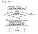
- FIG. 17 shows in detail a subroutine of a process of calculating an attitude of the controller in step 44 shown in FIG. 16 ;
- FIG. 18 shows in detail a subroutine of a process of calculating an acceleration change amount in step 45 shown in FIG. 16 ;
- FIG. 19 is a diagram illustrating an exemplary relationship between the real space in which a player moves the core unit 70 and a virtual game space displayed on a monitor 2 ;
- FIG. 20 is a diagram illustrating an example where parameters relating to the Y-axis direction change when a player moves upward the core unit 70 which has been at rest;
- FIG. 21 is a diagram illustrating an example where parameters relating to the Y-axis direction are changed when a player continues to move the core unit 70 ;
- FIG. 22 is a flow chart illustrating another example of a flow of the game process performed by the game apparatus body 5 ;
- FIG. 23 is a diagram illustrating another exemplary relationship between the real space in which a player moves the core unit 70 and a virtual game space displayed on a monitor 2 .
- FIG. 1 is an external view illustrating a game system 1 including a stationary game apparatus 3
- FIG. 2 is a block diagram illustrating the game apparatus body 5 .
- the game system 1 will be described.
- the game system 1 includes a home-use television receiver (hereinafter, referred to as a monitor) 2 typifying display means, and the stationary game apparatus 3 connected to the monitor 2 via a connection cord.
- the monitor 2 includes a speaker 2 a for outputting as a sound an audio signal outputted by the game apparatus body 5 .
- the game apparatus 3 includes the game apparatus body 5 and a controller 7 .
- the game apparatus body 5 has detachably mounted thereon an optical disc 4 on which a game is stored, and has a computer for executing the game program stored in the optical disc 4 so as to display a game screen on the monitor 2 .
- the controller 7 is used to supply, to the game apparatus body 5 , operation information necessary for a game in which a character and the like displayed on the game screen are controlled.
- the game apparatus body 5 incorporates a wireless controller module 19 (see FIG. 2 ).
- the wireless controller module 19 connects between the game apparatus body 5 and the controller 7 by radio communication such that the wireless controller module 19 receives data which is wirelessly transmitted by the controller 7 , and the game apparatus body 5 wirelessly transmits data to the controller 7 .
- the game apparatus body 5 has detachably mounted thereon the optical disc 4 typifying an exchangeable information storage medium.
- the game apparatus body 5 includes a flash memory 17 (see FIG. 2 ) serving as a backup memory for fixedly storing saved data and the like.
- the game apparatus body 5 executes the game program or the like stored on the optical disc 4 and displays a resultant game image on the monitor 2 .
- the game program and the like to be executed may be previously stored in the flash memory 17 instead of the optical disc 4 .
- the game apparatus body 5 can also reproduce a state of a game played in the past by using saved data stored in the flash memory 17 and display a game image on the monitor 2 . A player playing with the game apparatus body 5 can enjoy the game by operating the controller 7 while watching the game image displayed on the monitor 2 .
- the controller 7 wirelessly transmits transmission data, such as operation information, to the game apparatus body 5 incorporating the wireless controller module 19 , by using the technology of, for example, Bluetooth (registered trademark).
- the controller 7 includes two control units, a core unit 70 and a subunit 76 , connected to each other by a flexible connecting cable 79 .
- the controller 7 is operation means for mainly operating objects and the like displayed on the display screen of the monitor 2 .
- the core unit 70 and the subunit 76 each includes a housing which is small enough to be held by one hand, and a plurality of operation buttons, such as a cross key and a stick, exposed at the surface of the housing.
- the core unit 70 includes an imaging information calculation section 74 for taking an image viewed from the core unit 70 .
- two LED modules (hereinafter, referred to markers) 8 L and 8 R are provided in the vicinity of the display screen of the monitor 2 .
- the markers 8 L and 8 R each outputs infrared light or the like forward from the monitor 2 .
- the controller 7 may generate a sound or a vibration based on the transmission data.
- the subunit 76 may have a wireless unit, thereby eliminating the connection cable 79 .
- the subunit 76 has a Bluetooth (registered trademark) unit as the wireless unit, whereby the subunit 76 is allowed to transmit operation data to the core unit 70 .
- the game apparatus body 5 includes: the CPU (central processing unit) 10 ; a system LSI (large scale integration) 11 ; an external main memory 12 ; a ROM/RTC (read only memory/real time clock) 13 ; a disc drive 14 ; an AV-IC (audio video-integrated circuit) 15 , and the like.
- the CPU 10 serving as a game processor, executes the game program stored in the optical disc 4 so as to perform a game processing.
- the CPU 10 is connected to the system LSI 11 .
- the external main memory 12 In addition to the CPU 10 , the external main memory 12 , the ROM/RTC 13 , the disc drive 14 , and the AV-IC 15 are also connected to the system LSI 11 .
- the system LSI 11 performs processing such as control of data transmission between respective components connected thereto, generation of an image to be displayed, and acquisition of data from an external apparatus. An internal configuration of the system LSI 11 will be described below.
- the external main memory 12 which is of a volatile type, stores programs, such as a game program loaded from the optical disc 4 or the flash memory 17 , and various data, and is used as a work area and a buffer area for the CPU 10 .
- the ROM/RTC 13 includes a ROM (so-called a boot ROM) incorporating a program for booting the game apparatus body 5 , and a clock circuit (RTC) for counting time.
- the disc drive 14 reads, from the optical disc 4 , program data, texture data and the like, and writes the read data into an internal main memory 35 described below, or the external main memory 12 .
- an input/output processor 31 a GPU (graphics processor unit) 32 , a DSP (digital signal processor) 33 , a VRAM (video RAM) 34 , and the internal main memory 35 .
- a GPU graphics processor unit
- DSP digital signal processor
- VRAM video RAM
- the GPU 32 which is a part of rendering means, generates an image in accordance with a graphics command (draw command) from the CPU 10 .
- the VRAM 34 stores data (such as polygon data and texture data) necessary for the GPU 32 to execute the graphics command.
- the GPU 32 When an image is generated, the GPU 32 generates image data by using the data stored in the VRAM 34 .
- the DSP 33 functions as an audio processor, and generates audio data by using sound data and sound waveform (tone quality) data stored in the internal main memory 35 and the external main memory 12 .
- the image data and the audio data generated as described above, are read by the AV-IC 15 .
- the AV-IC 15 outputs the read image data to the monitor 2 via an AV connector 16 , and also outputs the read audio data to the speaker 2 a of the monitor 2 . Accordingly, the image is displayed on the monitor 2 , and the sound is outputted from the speaker 2 a.
- the input/output processor (I/O processor) 31 executes data reception and transmission among the components connected thereto and data downloading from an external apparatus.
- the input/output processor 31 is connected to the flash memory 17 , a wireless communication module 18 , the wireless controller module 19 , an extension connector 20 , and an external memory card connector 21 .
- an antenna 22 is connected, and to the wireless controller module 19 , an antenna 23 is connected.
- the input/output processor 31 is connected to a network via the wireless communication module 18 and the antenna 22 so as to communicate with other game apparatuses or various servers connected to the network.
- the input/output processor 31 accesses the flash memory 17 at regular intervals so as to detect for data to be transmitted to the network. When the data to be transmitted is detected, the data is transmitted to the network via the wireless communication module 18 and the antenna 22 . Further, the input/output processor 31 receives, via the network, the antenna 22 and the wireless communication module 18 , data transmitted from the other game apparatuses or data downloaded from a download server, and stores the received data in the flash memory 17 .
- the CPU 10 executes the game program so as to read the data stored in the flash memory 17 , thereby using the read data on the game program.
- the flash memory 17 may store not only the data transmitted and received among the game apparatus body 5 , and other game apparatuses or the various servers, but also saved data (result data or intermediate step data of the game) of a game played with the game
- the input/output processor 31 receives the operation data and the like transmitted from the controller 7 via the antenna 23 and the wireless controller module 19 , and (temporarily) stores the operation data and the like in a buffer area of the internal main memory 35 or the external main memory 12 .
- the internal main memory 35 may store various data and/or programs such as the game program read from the optical disc 4 , or the game program read from the flash memory 17 , and may be used as the work area or the buffer area of the CPU 10 .
- the input/output processor 31 is connected to the extension connector 20 and the external memory card connector 21 .
- the extension connector 20 which is an interface connector such as a USB and an SCSI, allows communication with the network, without using the wireless communication module 18 , by connecting, to the extension connector 20 , media such as an external storage medium, or a peripheral device such as another controller, or a wired communication connector.
- the external memory card connector 21 is a connector for connecting to the external memory card connector 21 the external storage medium such as a memory card.
- the input/output processor 31 accesses the external storage medium via the extension connector 20 or the external memory card connector 21 , so as to store data or read data.
- the game apparatus body 5 has, on the main front surface or the like, a power button 24 of the game apparatus body 5 , a reset button 25 for resetting a game process, an opening through which the optical disc 4 is mounted/dismounted, and an eject button 26 for ejecting the optical disc 4 from the game apparatus body 5 through the opening, and the like.
- the power button 24 and the reset button 25 are connected to the system LSI 11 .
- the power button 24 is pressed so as to be ON, the power is supplied to the respective components of the game apparatus body 5 via an AC adapter which is not shown.
- the reset button 25 is pressed, the system LSI 11 restarts a boot program of the game apparatus body 5 .
- the eject button 26 is connected to the disc drive 14 . When the eject button 26 is pressed, the optical disc 4 is ejected from the disc drive 14 .
- FIG. 3 is a perspective view illustrating an outer appearance of the controller 7 .
- the controller 7 includes the core unit 70 and the subunit 76 connected to each other by the connection cable 79 .
- the core unit 70 has a housing 71 including a plurality of operation sections 72 .
- the subunit 76 has a housing 77 including a plurality of operation sections 78 .
- connection cable 79 has a connector 791 detachably connected to the connector 73 of the core unit 70 at one end thereof, and the connection cable 79 is fixedly connected to the subunit 76 at the other end thereof.
- the connector 791 of the connection cable 79 is engaged with the connector 73 provided at the rear surface of the core unit 70 so as to connect between the subunit 76 and the core unit 70 by the connection cable 79 .
- FIG. 4 is a perspective view of the core unit 70 as viewed from the top rear side thereof.
- FIG. 5 is a perspective view of the core unit 70 as viewed from the bottom front side thereof.
- the core unit 70 includes the housing 71 formed by plastic molding or the like.
- the housing 71 has a generally parallelepiped shape extending in a longitudinal direction from front to rear.
- the overall size of the housing 71 is small enough to be held by one hand of an adult or even a child.
- a cross key 72 a is provided at the center of a front part of a top surface of the housing 71 .
- the cross key 72 a is a cross-shaped four-direction push switch.
- the cross key 72 a includes operation portions corresponding to the four directions (front, rear, right and left) represented by arrows, which are respectively located on cross-shaped projecting portions arranged at intervals of 90 degrees.
- the player selects one of the front, rear, right and left directions by pressing one of the operation portions of the cross key 72 a .
- the player can, for example, instruct a direction in which a player character or the like appearing in a virtual game world is to move or a direction in which the cursor is to move.
- the cross key 72 a is an operation section for outputting an operation signal in accordance with the aforementioned direction input operation performed by the player, such an operation section may be provided in another form.
- the cross key 72 a may be replaced with a composite switch including a push switch including a ring-shaped four-direction operation section and a center switch provided at the center thereof.
- the cross key 72 a may be replaced with an operation section which includes an inclinable stick projecting from the top surface of the housing 71 and outputs an operation signal in accordance with the inclining direction of the stick.
- the cross key 72 a may be replaced with an operation section which includes a disc-shaped member horizontally slidable and outputs an operation signal in accordance with the sliding direction of the disc-shaped member. Still alternatively, the cross key 72 a may be replaced with a touch pad. Still alternatively, the cross key 72 a may be replaced with an operation section which includes switches representing at least four directions (front, rear, right and left) and outputs an operation signal in accordance with the switch pressed by the player.
- a plurality of operation buttons 72 b , 72 c , 72 d , 72 e , 72 f and 72 g are provided.
- the operation buttons 72 b , 72 c , 72 d , 72 e , 72 f and 72 g are each an operation section for outputting a respective operation signal assigned to the operation buttons 72 b , 72 c , 72 d , 72 e , 72 f or 72 g when the player presses a head thereof.
- the operation buttons 72 b , 72 c , and 72 d are assigned with functions of a first button, a second button, and an A button, for example.
- the operation buttons 72 e , 72 f and 72 g are assigned with functions of a minus button, a home button and a plus button, for example.
- the operation buttons 72 b , 72 c , 72 d , 72 e , 72 f and 72 g are assigned with various functions in accordance with the game program executed by the game apparatus 3 .
- the operation buttons 72 b , 72 c and 72 d are arranged in a line at the center in the front-rear direction on the top surface of the housing 71 .
- the operation buttons 72 e , 72 f and 72 g are arranged in a line in the left-right direction between the operation buttons 72 b and 72 d on the top surface of the housing 71 .
- the operation button 72 f has a top surface thereof buried in the top surface of the housing 71 , so as not to be inadvertently pressed by the player.
- an operation button 72 h is provided in front of the cross key 72 a on the top surface of the housing 71 .
- the operation button 72 h is a power switch for remote-controlling the power of the game apparatus 3 to be on or off.
- the operation button 72 h also has a top surface thereof buried in the top surface of the housing 71 , so as not to be inadvertently pressed by the player.
- a plurality of LEDs 702 are provided.
- the controller 7 is assigned a controller type (number) so as to be distinguishable from the other controllers 7 .
- the LEDs 702 are used for informing the player of the controller type which is currently set to controller 7 that he or she is using.
- the wireless controller module 19 transmits, to the controller 7 , a signal for lighting one of the plurality of LEDs 702 corresponding to the controller type.
- a sound hole for outputting a sound from a speaker (speaker 706 shown in FIG. 6 ) between the operation button 72 b and the operation buttons 72 e , 72 f , and 72 g.
- a recessed portion is formed on a bottom surface of the housing 71 .
- the recessed portion is formed at a position at which an index finger or middle finger of the player is located when the player holds the core unit 70 .
- an operation button 72 i is provided on a slope surface of the recessed portion.
- the operation button 72 i is an operation section acting as, for example, a B button.
- the imaging information calculation section 74 is a system for analyzing image data taken by the core unit 70 and detecting the position of the center of gravity, the size and the like of an area having a high brightness in the image data.
- the imaging information calculation section 74 has, for example, a maximum sampling period of about 200 frames/sec., and therefore can trace and analyze even a relatively fast motion of the core unit 70 .
- the imaging information calculation section 74 will be described below in detail.
- the connector 73 is provided on a rear surface of the housing 71 .
- the connector 73 is, for example, an edge connector, and is used for engaging and connecting the core unit 70 with, for example, the connection cable.
- a coordinate system is defined for the core unit 70 .
- XYZ-axes orthogonal to each other are defined for the core unit 70 .
- the Z-axis is defined along the longitudinal direction of the housing 71 corresponding to the front-rear direction of the core unit 70 , and the direction toward the front surface (the surface on which the imaging information calculation section 74 is provided) of the core unit 70 is defined as the Z-axis positive direction.
- the Y-axis is defined along the top-bottom direction of the core unit 70 , and the direction toward the top surface (the surface on which the operation button 72 a is provided) of the housing 71 is defined as the Y-axis positive direction.
- the X-axis is defined along the right-left direction of the core unit 70 , and the direction toward the left side surface (the side surface shown in FIG. 5 but not shown in FIG. 4 ) of the housing 71 is defined as the X-axis positive direction.
- FIG. 6 is a perspective view illustrating a state where an upper casing (a part of the housing 71 ) of the core unit 70 is removed, as viewed from the rear surface side of the core unit 70 .
- FIG. 7 is a perspective view illustrating a state where a lower casing (a part of the housing 71 ) of the core unit 70 is removed, as viewed from the front surface side of the core unit 70 .
- FIG. 7 is a perspective view illustrating a reverse side of a substrate 700 shown in FIG. 6 .
- the substrate 700 is fixed inside the housing 71 .
- the operation buttons 72 a , 72 b , 72 c , 72 d , 72 e , 72 f , 72 g and 72 h , an acceleration sensor 701 , the LEDs 702 , an antenna 754 and the like are provided.
- These elements are connected to a microcomputer 751 (see FIGS. 7 and 10 ) and the like via lines (not shown) formed on the substrate 700 and the like.
- the wireless module 753 (see FIG. 10 ) and the antenna 754 allow the core unit 70 to act as a wireless controller.
- a quartz oscillator (not shown), provided in the housing 71 , generates a reference clock of the microcomputer 751 described below.
- the speaker 706 and an amplifier 708 are provided on a top main surface of the substrate 700 .
- the acceleration sensor 701 is provided not at the center portion of the substrate 700 but near the periphery of the substrate 700 . Accordingly, the acceleration sensor 701 is allowed to detect for both a direction change of the gravitational acceleration and an acceleration containing a component generated due to centrifugal force, in accordance with the core unit 70 rotating about the longitudinal direction thereof. Therefore, by performing a predetermined calculation, it is possible to determine a movement of the core unit 70 , with preferable accuracy, based on the acceleration data having been detected.
- the imaging information calculation section 74 includes an infrared filter 741 , a lens 742 , the image pickup element 743 and an image processing circuit 744 located in order, respectively, from the front surface of the core unit 70 on the bottom main surface of the substrate 700 .
- the connector 73 is attached.
- a sound IC 707 and the microcomputer 751 are provided on the bottom main surface of the substrate 700 .
- the sound IC 707 is connected to the microcomputer 751 and the amplifier 708 via a wiring formed on the substrate 700 and the like, and outputs an audio signal to the speaker 706 via the amplifier 708 in accordance with sound data transmitted from the game apparatus body 5 .
- a vibrator 704 is provided on the bottom main surface of the substrate 700 .
- the vibrator 704 may be, for example, a vibration motor or a solenoid.
- the core unit 70 is vibrated by an actuation of the vibrator 704 , and the vibration is conveyed to the player's hand holding the core unit 70 .
- the vibrator 704 is positioned slightly in front of the longitudinal center of the housing 71 , and therefore a vibration of the housing 71 is enhanced so as to allow a player holding the core unit 70 to easily feel the core unit 70 vibrating.
- FIG. 8 is a perspective view of an example of the subunit 76 .
- FIG. 9 is a perspective view illustrating a state where an upper casing (a part of the housing 77 ) of the subunit 76 shown in FIG. 8 is removed.
- the subunit 76 includes the housing 77 formed by, for example, plastic molding.
- the housing 77 extends in a longitudinal direction from front to rear, and has a streamline solid shape including a head which is a widest portion in the subunit 76 .
- the overall size of the subunit 76 is small enough to be held by one hand of an adult or even a child.
- the stick 78 a is an operation section which includes an inclinable stick projecting from the top surface of the housing 77 and outputs an operation signal in accordance with the inclining direction and/or inclination amount of the stick.
- a player can optionally designate any direction or any position by inclining a stick tip in any direction of 360 degrees, whereby the player can instruct a direction in which a player character or the like appearing in a virtual game world is to move. Further, the player can instruct an amount of movement of the player character or the like by using the amount of inclination of the stick 78 a.
- the stick 78 a is an operation section for outputting an operation signal in accordance with a direction input operation performed by the player
- an operation section may be provided in another form.
- the stick 78 a may be replaced with a cross key as described above or a composite switch including a push switch having a ring-shaped four-direction operation section and a center switch provided at the center thereof.
- the stick 78 a may be replaced with an operation section which includes a disc-shaped member horizontally slidable and outputs an operation signal in accordance with the sliding direction of the disc-shaped member.
- the stick 78 a may be replaced with a touch pad.
- the stick 78 a may be replaced with an operation section which has switches representing at least four directions (front, rear, right and left), and outputs an operation signal in accordance with the switch pressed by a player
- the operation buttons 78 d and 78 e are each an operation section for outputting a respective operation signal assigned to the operation buttons 72 d and 78 e when the player presses a head thereof.
- the operation buttons 78 d and 78 e are assigned with functions of an X button and a Y button, for example.
- the operation buttons 78 d and 78 e are assigned with various functions in accordance with the game program executed by the game apparatus 3 . In the exemplary arrangement shown in FIG. 8 , the operation buttons 78 d and 78 e are arranged in a line in the top-bottom direction on the front surface of the housing 77 .
- a substrate is fixedly provided in the housing 77 .
- the stick 78 a , the acceleration sensor 761 and the like are provided so as to be connected to the connection cable 79 via a wiring (not shown) formed on the substrate or the like.
- the acceleration sensor 761 is positioned at the intersection of the longitudinal center and transverse center of the housing 77 .
- a coordinate system is defined for the subunit 76 .
- XYZ-axes orthogonal to each other are defined for the subunit 76 .
- the Z-axis is defined along the longitudinal direction of the housing 77 corresponding to the front-rear direction of the subunit 76 , and the direction toward the front surface (the surface on which the operation buttons 78 d and 78 e are provided) of the subunit 76 is defined as the Z-axis positive direction.
- the Y-axis is defined along the top-bottom direction of the subunit 76 , and the direction (the direction in which the stick 78 a projects) toward the top surface of the housing 77 is defined as the Y-axis positive direction.
- the X-axis is defined along the right-left direction of the subunit 76 , and the direction toward the left side surface (the side surface shown in FIG. 8 ) of the housing 77 is defined as the X-axis positive direction.
- FIG. 10 is a block diagram illustrating a structure of the controller 7 .
- the core unit 70 includes the communication section 75 in addition to the operation section 72 , the imaging information calculation section 74 , the acceleration sensor 701 , the vibrator 704 , the speaker 706 , the sound IC 707 , and the amplifier 708 , which are described above.
- the subunit 76 includes the operation section 78 and the acceleration sensor 761 as described above, and is connected to the microcomputer 751 via the connection cable 79 , and the connectors 791 and 73 .
- the imaging information calculation section 74 includes the infrared filter 741 , the lens 742 , the image pickup element 743 and the image processing circuit 744 .
- the infrared filter 741 allows only infrared light to pass therethrough, among light incident on the front surface of the core unit 70 .
- the lens 742 collects the infrared light which has passed through the infrared filter 741 and outputs the infrared light to the image pickup element 743 .
- the image pickup element 743 is a solid-state image pick-up device such as, for example, a CMOS sensor or a CCD.
- the image pickup element 743 takes an image of the infrared light collected by the lens 742 .
- the image pickup element 743 takes an image of only the infrared light which has passed through the infrared filter 741 and generates image data.
- the image data generated by the image pickup element 743 is processed by the image processing circuit 744 .
- the image processing circuit 744 processes the image data obtained from the image pickup element 743 , identifies a spot thereof having a high brightness, and outputs process result data representing the identified position coordinate point and size of the area to the communication section 75 .
- the imaging information calculation section 74 is fixed to the housing 71 of the core unit 70 .
- the imaging direction of the imaging information calculation section 74 can be changed by changing the direction of the housing 71 .
- the core unit 70 preferably includes a three-axis (X-axis, Y-axis, and Z-axis) acceleration sensor 701 .
- the subunit 76 preferably includes a three-axis (X-axis, Y-axis, and Z-axis) acceleration sensor 761 .
- the three axis acceleration sensors 701 and 761 each detects a linear acceleration in three directions, that is, the up/down direction, the left/right direction, and the forward/backward direction (the XYZ-axial directions as described above).
- two-axis acceleration detection means for detecting only a linear acceleration along the up/down direction and the left/right direction (or any other paired directions) may be used, or one-axis acceleration detection means for detecting only a linear acceleration along any one of the three axes may be used, depending on a type of a control signal used for a game process.
- the one to three axis acceleration sensors 701 and 761 may be of the type available from Analog Devices, Inc. or STMicroelectronics N.V.
- each of the acceleration sensors 701 and 761 is of electrostatic capacitance (capacitance-coupling) type that is based on silicon micro-machined MEMS (Micro Electro Mechanical Systems) technology.
- any other suitable technology of acceleration detection means for example, piezoelectric type or piezoresistance type
- any other suitable technology of acceleration detection means for example, piezoelectric type or piezoresistance type
- acceleration detection means as used in the acceleration sensors 701 and 761 , is only capable of detecting an acceleration (linear acceleration) along a straight line corresponding to each axis of the acceleration sensor.
- the direct output of each of the acceleration sensors 701 and 761 is limited to signals indicative of the linear acceleration (static or dynamic) along each of the one, two or three axes thereof.
- each of the acceleration sensors 701 and 761 cannot directly detect movement along a non-linear (e.g. arcuate) path, rotation, rotational movement, angular displacement, tilt, position, attitude, or any other physical characteristic.
- a computer such as a processor (for example, the CPU 10 ) of the game apparatus or a processor (for example, the microcomputer 751 ) of the core unit 70 or the subunit 76 processes acceleration signals outputted from each of the acceleration sensors 701 and 761
- additional information relating to the core unit 70 and the subunit 76 can be inferred or calculated (determined), as one skilled in the art will readily understand from the description herein.
- each of the acceleration sensors 701 and 761 capable of detecting an acceleration in multi-axial directions subjects, to a processing, the acceleration signals having been detected in the respective axes, so as to more specifically determine the degree to which the core unit 70 and the subunit 76 each tilts relative to the gravity direction.
- the processor may calculate, based on the outputs from the acceleration sensors 701 and 761 , data representing an angle at which each of the core unit 70 and the subunit 76 tilts, approximate degrees to which the core unit 70 and the subunit 76 tilt may be inferred based on the outputs from the acceleration sensors 701 and 761 without calculating the data representing the angle of the tilt.
- the acceleration sensors 701 and 761 are used in combination with the processor, the tilt, attitude, or position of each of the core unit 70 and the subunit 76 can be determined.
- the acceleration sensors 701 and 761 detect accelerations based on movements of the acceleration sensors 701 and 761 , respectively, in addition to the gravitational acceleration component. Therefore, when the gravitational acceleration components are eliminated through a predetermined process, it is possible to determine, for example, directions in which the core unit 70 and the subunit 76 move. Specifically, when the core unit 70 including the acceleration sensor 701 and the subunit 76 including the acceleration sensor 761 are dynamically accelerated and moved with hands of a player, it is possible to calculate various movements and/or positions of the core unit 70 and the subunit 76 by processing the acceleration signals generated by the acceleration sensors 701 and 761 .
- the accelerations based on the movements of the acceleration sensors 701 and 761 are eliminated through a predetermined process, whereby it is possible to determine the tilts of the core unit 70 and the subunit 76 relative to the gravity direction.
- each of the acceleration sensors 701 and 761 may include an embedded signal processor or another type of dedicated processor for performing any desired processing of the acceleration signals outputted by embedded acceleration detection means prior to outputting signals to the microcomputer 751 .
- the embedded or dedicated processor could convert the detected acceleration signal to a corresponding tilt angle.
- Data representing the respective accelerations detected by the acceleration sensors 701 and 761 are outputted to the communication section 75 .
- an acceleration applied to the core unit 70 and/or the subunit 76 has the same direction as the direction in which the player moves the core unit 70 and/or the subunit 76 , and thereafter a magnitude of the acceleration is gradually reduced, and, at the end of the moving, the acceleration applied to the core unit 70 and/or the subunit 76 has a direction opposite to the direction in which the player moves the core unit 70 and/or the subunit 76 .
- an acceleration vector outputted by each of the acceleration sensors 701 and 761 has a direction precisely opposite to the direction in which the acceleration is applied to each of the core unit 70 and the subunit 76 , or a sign (plus or minus) of an acceleration outputted by each of the acceleration sensors 701 and 761 is different from a sign represented by the direction in which the acceleration is applied to each of the core unit 70 and the subunit 76 . Therefore, in the following description, the acceleration sensors 701 and 761 have characteristics that data outputted by the acceleration sensors 701 and 761 represent accelerations having directions precisely opposite to the directions in which the accelerations are applied to the acceleration sensors 701 and 761 , respectively.
- the acceleration sensors 701 and 761 have characteristics that data outputted by the acceleration sensors 701 and 761 represent accelerations having directions precisely opposite to the directions in which the core unit 70 and the subunit 76 , respectively, are actually accelerated. Specifically, each of the acceleration sensors 701 and 761 outputs acceleration data based on an inertial force generated by the acceleration. On the other hand, the gravitational acceleration applied to each of the acceleration sensors 701 and 761 of the core unit 70 and the subunit 76 , respectively, being in static states is outputted as acceleration data representing the same direction as the gravity direction.
- the communication section 75 includes the microcomputer 751 , a memory 752 , the wireless module 753 and the antenna 754 .
- the microcomputer 751 controls the wireless module 753 for wirelessly transmitting the transmission data while using the memory 752 as a storage area during the processing.
- the microcomputer 751 controls operations of the sound IC 707 and the vibrator 704 based on the data received from the game apparatus body 5 by the wireless module 753 via the antenna 754 .
- the sound IC 707 processes the sound data and the like transmitted from the game apparatus body 5 via the communication section 75 .
- the microcomputer 751 actuates the vibrator 704 based on, for example, the vibration data (for example, a signal for powering the vibrator 704 ON or OFF) transmitted by the game apparatus body 5 via the communication section 75 .
- Data from the core unit 70 including an operation signal (core key data) from the operation section 72 , an acceleration signal (core acceleration data) from the acceleration sensor 701 , and the process result data from the imaging information calculation section 74 are outputted to the microcomputer 751 .
- An operation signal (sub key data) from the operation section 78 of the subunit 76 and an acceleration signal (sub acceleration data) from the acceleration sensor 761 are outputted to the microcomputer 751 via the connection cable 79 .
- the microcomputer 751 temporarily stores the respective input data (core key data, sub key data, core acceleration data, sub acceleration data, and process result data) in the memory 752 as the transmission data which is to be transmitted to the wireless controller module 19 .
- the wireless transmission from the communication section 75 to the wireless controller module 19 is performed periodically at predetermined time intervals. Since game process is generally performed at a cycle of 1/60 sec., data needs to be collected and transmitted at a cycle of a time period shorter than the cycle of the game process. Specifically, the game process unit is 16.7 ms ( 1/60 sec.), and the transmission interval of the communication section 75 structured using the Bluetooth (registered trademark) technology is 5 ms.
- the microcomputer 751 outputs the transmission data stored in the memory 752 as a series of operation information to the wireless module 753 .
- the wireless module 753 uses, for example, the Bluetooth (registered trademark) technology to modulate the operation information onto a carrier wave of a predetermined frequency, and radiates the low power radio wave signal from the antenna 754 .
- the core key data from the operation section 72 included in the core unit 70 the sub key data from the operation section 78 included in the subunit 76 , the core acceleration data from the acceleration sensor 701 of the core unit 70 , the sub acceleration data from the acceleration sensor 761 of the subunit 76 , and the process result data from the imaging information calculation section 74 are modulated onto the low power radio wave signal by the wireless module 753 and radiated from the core unit 70 .
- the wireless controller module 19 of the game apparatus 3 receives the low power radio wave signal, and the game apparatus 3 demodulates or decodes the low power radio wave signal to obtain the series of operation information (the core key data, the sub key data, the core acceleration data, the sub acceleration data, and the process result data). Based on the obtained operation information and the game program, the CPU 10 of the game apparatus 3 performs the game process.
- each of the core unit 70 and the subunit 76 is small enough to be held by one hand of an adult or even a child.
- a player moves the core unit 70 held with one hand (for example, a right hand), and the subunit 76 held with the other hand (for example, a left hand).
- FIG. 11 shows a state where a player moves upward and downward each of the core unit 70 held with the right hand, and the subunit 76 held with the left hand.
- the game apparatus body 5 determines movements of the core unit 70 and the subunit 76 , and determines positions, in a virtual game space, based on the movements of the core unit 70 and the subunit 76 , thereby performing a game process.
- the player moves the core unit 70 held with one hand (for example, the right hand).
- the game apparatus body 5 determines a movement of the core unit 70 in accordance with the player moving the core unit 70 , and determines a position, in the virtual game space, based on the movement of the core unit 70 , thereby performing the game process.
- operation information (specifically, the X, Y, and Z axial direction acceleration data contained in the core acceleration data and the sub acceleration data) representing attitudes of the core unit 70 and the subunit 76 each of which is in a static state is supplied to the game apparatus body 5 .
- operation information representing dynamic states based on, for example, centrifugal force and/or accelerations applied in the direction in which the core unit 70 and the subunit 76 are moved, is supplied from the core unit 70 and the subunit 76 to the game apparatus body 5 .
- the changes of accelerations applied to the core unit 70 and the subunit 76 can be detected by the acceleration sensors 701 and 761 , respectively, and therefore when the X, Y, and Z axial direction acceleration data outputted by each of the acceleration sensors 701 and 761 is subjected to an additional processing, attitudes of the core unit 70 and the subunit 76 in the static state and actions of the core unit 70 and the subunit 76 in the dynamic state can be calculated.
- an acceleration vector outputted by each of the acceleration sensors 701 and 761 has a direction precisely opposite to the direction in which each of the core unit 70 and the subunit 76 is accelerated, or a sign (plus or minus) of an acceleration outputted by each of the acceleration sensors 701 and 761 is different from a sign represented by the direction in which each of the core unit 70 and the subunit 76 is accelerated. Therefore, when an acceleration based on an action is detected, it should be understood that it is necessary to calculate a tilt and a movement of each of the core unit 70 and the subunit 76 in consideration of a direction of an acceleration having been detected.
- FIGS. 12 to 14 are diagrams each illustrating an example of a game process or an information processing performed in accordance with a movement of the controller 7 .
- Examples of the game process will be described. That is, an object displayed on the monitor 2 is moved in accordance with movements of the core unit 70 and the subunit 76 (for example, a drum is hit with two sticks in the virtual game space displayed on the monitor 2 ), or an object displayed on the monitor 2 is moved in accordance with a movement of the core unit 70 (for example, a character in the virtual game space displayed on the monitor 2 is rotated or an item positioned in the virtual game space is moved in accordance with a movement of the core unit 70 ).
- an example of an information processing other than the game process will be described. That is, a gesture for a browser displayed on a display is made in accordance with the core unit 70 and/or the subunit 76 being moved (for example, move a window, close a window, or turn a page).
- FIG. 12 displayed on the monitor 2 are two stick objects OBJ 1 and OBJ 2 , and a drum object D all of which are positioned in the virtual game space.
- the stick object OBJ 1 is moved downward toward a strike surface of the drum object D in the virtual game space in accordance with the core unit 70 being moved downward (a state represented by a solid line in FIG. 12 ).
- the stick object OBJ 1 is returned to a reference position in the virtual game space (a state represented by a dotted line in FIG. 12 ).
- the stick object OBJ 2 is moved downward toward the strike surface of the drum object D in the virtual game space in accordance with the subunit 76 being moved downward (a state represented by a dotted line in FIG. 12 ).
- the stick object OBJ 2 is returned to a reference position in the virtual game space (a state represented by a solid line in FIG. 12 ).
- a character object OBJ which is connected to an axis point C and rotates about the axis point C in the virtual game space.
- the character object OBJ is rotated about the axis point C in the virtual game space in accordance with the core unit 70 being moved so as to form a circle.
- an angular velocity at which the character object OBJ is rotated about the axis point C is determined so as to be in synchronization with the movement of the core unit 70 forming the circle.
- the character object OBJ stops so as to hang on the axis point C when the core unit 70 stops.
- an item object OBJ displayed on the monitor 2 is an item object OBJ positioned in the virtual game space.
- the item object OBJ is moved on the display screen in accordance with the core unit 70 being moved while a predetermined button is pressed.
- the CPU 10 calculates parameters indicating positions to which the core unit 70 and the subunit 76 are moved from positions at which the movements of the core unit 70 and the subunit 76 have been started.
- the CPU 10 scales each of the parameters in the virtual game space so as to designate a coordinate point corresponding to each of the parameters, and each of the stick objects OBJ 1 and OBJ 2 , the character object OBJ, and the item object OBJ is moved to a position represented by the coordinate point.
- the stick objects OBJ 1 and OBJ 2 , the character object OBJ, and the item object OBJ are, for example, moved downward, rotated, or moved in the same manners as a player moves the core unit 70 and/or the subunit 76 , so that the player is allowed to feel as if the player is playing the drum, rotating the character, and moving the item.
- an object in the virtual game space may be returned to the reference position (for example, an exemplary game as shown in FIG. 12 or FIG.
- FIG. 15 is a diagram illustrating main data to be stored in the external main memory 12 and/or in the internal main memory 35 (hereinafter, two main memories are collectively referred to simply as a main memory) of the game apparatus body 5 .
- the main memory stores most recent acceleration data Da, final acceleration data Db, acceleration change amount data Dc, accumulation vector data Dd, following vector data De, differential vector data Df, virtual game space position data Dg, attitude data Dh, image data Di, and the like.
- the main memory also stores data necessary for the game process, such as data relating to, for example, object OBJ and other objects appearing in the game, and data (e.g., background data) relating to the virtual game space, in addition to the data contained in the information shown in FIG. 15 .
- the most recent acceleration data Da represents a most recent acceleration accn generated in the core unit 70 , and has its data updated to most recent core acceleration data contained in a series of operation information transmitted as the transmission data from the core unit 70 .
- the most recent acceleration data Da includes: X-axis direction acceleration data Da 1 representing an acceleration accnX detected in an X-axial component by the acceleration sensor 701 ; Y-axis direction acceleration data Da 2 representing an acceleration accnY detected in a Y-axial component by the acceleration sensor 701 ; and Z-axis direction acceleration data Da 3 representing an acceleration accnZ detected in a Z-axial component by the acceleration sensor 701 .
- the wireless controller module 19 included in the game apparatus body 5 receives core acceleration data contained in the operation information transmitted from the core unit 70 at predetermined intervals (for example, every 1/200 seconds), and stores the core acceleration data in a buffer (not shown) of the wireless controller module 19 . Thereafter, the most recent core acceleration data in the buffer is read for each frame (for example, every 1/60 seconds) corresponding to a game process cycle, so as to update the most recent acceleration data Da stored in the main memory.
- the most recent acceleration data Da has its data updated for each frame corresponding to the game process cycle.
- the most recent acceleration data Da may have its data updated in another process cycle.
- the most recent acceleration data Da has its data updated at every transmission cycle of the core unit 70 , and the updated core acceleration data may be used at every game process cycle.
- a cycle in which the most recent acceleration data Da representing the acceleration data Da 1 , Da 2 and Da 3 has its data updated is different from the game process cycle.
- the final acceleration data Db represents a final acceleration accl which corresponds to the most recent acceleration accn used for calculating an acceleration change amount accv.
- the final acceleration data Db includes: X-axis direction acceleration data Db 1 representing a final acceleration acclX relating to the X-axial component; Y-axis direction acceleration data Db 2 representing a final acceleration acclY relating to the Y-axial component; and Z-axis direction acceleration data Db 3 representing a final acceleration acclZ relating to the Z-axial component, as with the most recent acceleration data Da.
- the acceleration change amount data Dc represents an acceleration change amount accv which corresponds to an amount of change between the most recent acceleration accn and the final acceleration accl.
- the acceleration change amount data Dc includes: X-axis direction acceleration change amount data Dc 1 representing an acceleration change amount accvX relating to the X-axial component; Y-axis direction acceleration change amount data Dc 2 representing an acceleration change amount accvY relating to the Y-axial component; and Z-axis direction acceleration change amount data Dc 3 representing an acceleration change amount accvZ relating to the Z-axial component.
- the acceleration change amount accv contains the acceleration change amount for each axis, that is, the acceleration change amount accvX, the acceleration change amount accvY, and the acceleration change amount accvZ, and also represents a change amount vector representing an amount of change between the most recent acceleration accn and the final acceleration accl.
- the accumulation vector data Dd represents an accumulation vector veca obtained by accumulating the most recent acceleration accn.
- the accumulation vector data Dd includes: X-axis direction component data Dd 1 representing an X-axial component vecaX of the accumulation vector veca; Y-axis direction component data Dd 2 representing a Y-axial component vecaY of the accumulation vector veca; and Z-axis direction component data Dd 3 representing a Z-axial component vecaZ of the accumulation vector veca.
- the following vector data De represents a following vector vecg which follows the accumulation vector veca (in the present example, the most recent accumulation vector veca) at a predetermined rate.
- the following vector data De includes: X-axis direction component data De 1 representing an X-axial component vecgX of the following vector vecg; Y-axis direction component data De 2 representing a Y-axial component vecgY of the following vector vecg; and Z-axis direction component data De 3 representing a Z-axial component vecgZ of the following vector vecg.
- the differential vector data Df represents a differential vector vecd between the accumulation vector veca and the following vector vecg.
- the differential vector data Df includes: X-axis direction component data Df 1 representing an X-axial component vecdX of the differential vector vecd; Y-axis direction component data Df 2 representing a Y-axial component vecdY of the differential vector vecd; and Z-axis direction component data Df 3 representing a Z-axial component vecdZ of the differential vector vecd.
- the virtual game space position data Dg represents a position pos of an object in the virtual game space, and the position pos is determined based on the differential vector vecd.
- the virtual game space position data Dg includes: x-axis coordinate data Dg 1 representing an x-axis coordinate point posx of the position pos of an object; y-axis coordinate data Dg 2 representing a y-axis coordinate point posy of the position pos of the object; and z-axis coordinate data Dg 3 representing a z-axis coordinate point posz of the position pos of the object.
- the attitude data Dh represents an attitude of the core unit 70 in a static state as, for example, a three-dimensional vector representing a direction of the gravitational acceleration applied to the core unit 70 .
- the image data Di includes object image data Di 1 and the like.
- the object image data Di 1 is used for positioning the object OBJ at the position pos in the virtual game space so as to generate a game image.
- FIG. 16 is a flow chart illustrating a flow of the game process executed by the game apparatus body 5 .
- FIG. 17 shows a sub-routine illustrating in detail a process of calculating an attitude of the controller in step 44 shown in FIG. 16 .
- FIG. 18 shows a sub-routine illustrating in detail a process of calculating the acceleration change amount in step 45 shown in FIG. 16 .
- the CPU 10 of the game apparatus body 5 executes a boot program stored in the boot ROM not shown so as to initialize each unit such as the main memory.
- the game program stored in the optical disc 4 is loaded to the main memory and the CPU 10 starts to execute the game program.
- the flow charts of FIGS. 16 to 18 show a game process performed after these process steps are completed.
- the CPU 10 performs a game process initialization in step 41 , and advances the process to the next step.
- the game process initialization of step 41 includes initializations, such as setting of the virtual game space and positioning of game objects, in the case of the game process in which two sticks are moved downward so as to play the drum in the virtual game space, a character is rotated, or an item is moved.
- the CPU 10 performs determination process initialization in step 42 , and advances the process to the next step.
- the determination process initialization of step 42 parameters used for calculating a movement of the core unit 70 are initialized. For example, the CPU 10 sets, to zero, each of the final accelerations acclX, acclY, and acclZ which are represented by the final acceleration data Db.
- the CPU 10 sets, to zero, each of the acceleration change amounts accvX, accvY, and accvZ which are represented by the acceleration change amount data Dc.
- the CPU 10 sets, to zero, each of the components vecaX, vecaY, and vecaZ which are represented by the accumulation vector data Dd.
- the CPU 10 sets, to zero, each of the components vecgX, vecgY, and vecgZ which are represented by the following vector data De.
- the CPU 10 sets, to zero, each of the components vecdX, vecdY, and vecdZ which are represented by the differential vector data Df.
- the CPU 10 sets, to zero, each of the coordinate points posx, posy, and posz which are represented by the virtual game space position data Dg.
- the CPU 10 sets, as a three-dimensional vector having a length of 1 and a predetermined direction, an attitude of the core unit 70 in the static state represented by the attitude data Dh.
- the CPU 10 acquires the most recent acceleration accn in step 43 , and advances the process to the next step.
- the CPU 10 updates the most recent acceleration data Da so as to represent, as the most recent acceleration accn, an acceleration represented by the core acceleration data contained in the operation information having been most recently received from the core unit 70 .
- the X-axis direction acceleration data Da 1 is updated so as to represent, as the most recent acceleration accnX, an acceleration represented by X-axis direction core acceleration data contained in the operation information having been most recently received from the core unit 70 .
- the Y-axis direction acceleration data Da 2 is updated so as to represent, as the most recent acceleration accnY, an acceleration represented by Y-axis direction core acceleration data contained in the operation information having been most recently received from the core unit 70 .
- the Z-axis direction acceleration data Da 3 is updated so as to represent, as the most recent acceleration accnZ, an acceleration represented by Z-axis direction core acceleration data contained in the operation information having been most recently received from the core unit 70 .
- the CPU 10 calculates an attitude of the core unit 70 in step 44 , and advances the process to the next step.
- the process of calculating the attitude of the core unit 70 in step 44 will be described.
- the CPU 10 determines in step 61 whether or not the core unit 70 is in a static state, based on the most recent acceleration accn represented by the most recent acceleration data Da. For example, the CPU 10 determines that the core unit 70 is not in the static state when a value represented by at least one of the most recent accelerations accnX, accnY or accnZ is greater than or equal to a value corresponding to the gravitational acceleration. As another example, the CPU 10 determines that the core unit 70 is in the static state when each of the change amounts relating to the most recent accelerations accnX, accnY, and accnZ has a value smaller than a predetermined value.
- step 62 the CPU 10 calculates the attitude of the core unit 70 using the most recent acceleration accn so as to update the attitude data Dh, and ends the process according to the sub-routine.
- the gravitational acceleration is applied to the core unit 70 .
- the direction in which the gravitational acceleration is applied to the core unit 70 can be calculated based on the most recent accelerations accnX, accnY, and accnZ.
- the direction in which the gravitational acceleration is applied to the core unit 70 is a vertical downward direction in a real space, and it is possible to acquire the vertical downward direction which is represented by using the XYZ axes defined for the core unit 70 .
- the CPU 10 updates the attitude data Dh so as to represent the attitude of the core unit 70 in the static state as three-dimensional vector data representing the direction of the gravitational acceleration relative to the core unit 70 .
- the CPU 10 calculates the acceleration change amount accv in step 45 , and advances the process to the next step.
- an acceleration change amount calculation process in step 45 will be described.
- the CPU 10 determines whether or not the most recent acceleration accnX represented by the X-axis direction acceleration data Da 1 contained in the most recent acceleration data Da reaches a measurement limit of the acceleration sensor 701 .
- the acceleration sensor 701 and the acceleration sensor 761 are each allowed to measure an acceleration within its measurable range. When the acceleration has a value outside the measurable range, each of the acceleration sensor 701 and the acceleration sensor 761 may output an upper limit value (lower limit value) of the measurable range.
- the acceleration sensor 701 and the acceleration sensor 761 are each allowed to measure an acceleration within the measurable range from ⁇ 4G to +4G, and an acceleration of more than 4G is applied to each of the core unit 70 and the subunit 76 , the acceleration sensor 701 and the acceleration sensor 761 each outputs the acceleration data representing ⁇ 4G or +4G.
- step 81 whether or not the acceleration applied to the core unit 70 has a value within the acceleration measurable range is determined. For example, values close to the upper and lower limit values of the acceleration measurable range are used as threshold values (for example, ⁇ 3.39G and +3.39G).
- the CPU 10 determines that the most recent acceleration accnX reaches the measurement limit of the acceleration sensor 701 .
- the CPU 10 advances the process to step 82 .
- the CPU 10 advances the process to step 83 .
- step 82 the CPU 10 calculates the acceleration change amount accvX in the X-axis direction so as to update the X-axis direction acceleration change amount data Dc 1 , and advances the process to step 85 .
- the CPU 10 calculates the acceleration change amount accvX by subtracting, from the most recent acceleration accnX which is currently stored, the final acceleration acclX which is currently stored.
- step 83 the CPU 10 performs a calculation for estimating the acceleration change amount accvX so as to update the X-axis direction acceleration change amount data Dc 1 , and advances the process to the next step. For example, in step 83 , the CPU 10 multiplies, by a predetermined attenuation rate, the acceleration change amount accvX which is currently stored (that is, the acceleration change amount accvX immediately preceding the acceleration change amount accvX which is being currently calculated), so as to update the acceleration change amount accvX, so that the X-axis direction acceleration change amount data Dc 1 has its data updated.
- the value by which the acceleration change amount accvX is multiplied represents an attenuation rate of the acceleration change amount, which allows the estimation of a value of an acceleration outside the measurable range of the acceleration sensor 701 , and the value, i.e., the attenuation rate is a positive value (for example, 0.6) smaller than one.
- the CPU 10 changes the most recent acceleration accnX using the acceleration change amount accvX having been calculated in step 83 so as to update the X-axis direction acceleration data Da 1 in step 84 , and advances the process to step 85 .
- the CPU 10 adds the acceleration change amount accvX having been calculated in step 83 to the most recent acceleration accnX which is currently stored so as to update the most recent acceleration accnX, thereby updating the X-axis direction acceleration data Da 1 .
- step 85 the CPU 10 determines whether or not the most recent acceleration accnY represented by the Y-axis direction acceleration data Da 2 contained in the most recent acceleration data Da reaches a measurement limit of the acceleration sensor 701 .
- a measurement limit of the acceleration sensor 701 For example, values close to the upper and lower limit values of the acceleration measurable range are used as threshold values (for example, ⁇ 3.39G and +3.39G), as with in step 81 .
- the CPU 10 determines that the most recent acceleration accnY reaches the measurement limit of the acceleration sensor 701 .
- the CPU 10 advances the process to step 86 .
- the CPU 10 advances the process to step 87 .
- step 86 the CPU 10 calculates the acceleration change amount accvY in the Y-axis direction so as to update the Y-axis direction acceleration change amount data Dc 2 , and advances the process to step 89 .
- the CPU 10 calculates the acceleration change amount accvY by subtracting, from the most recent acceleration accnY which is currently stored, the final acceleration acclY which is currently stored.
- step 87 the CPU 10 performs a calculation for estimating the acceleration change amount accvY so as to update the Y-axis direction acceleration change amount data Dc 2 , and advances the process to the next step.
- the CPU 10 multiplies, by the predetermined attenuation rate, the acceleration change amount accvY which is currently stored (that is, the acceleration change amount accvY immediately preceding the acceleration change amount accvY which is being currently calculated), so as to update the acceleration change amount accvY, so that the Y-axis direction acceleration change amount data Dc 2 has its data updated.
- the CPU 10 changes the most recent acceleration accnY using the acceleration change amount accvY having been calculated in step 87 so as to update the Y-axis direction acceleration data Da 2 in step 88 , and advances the process to step 89 .
- the CPU 10 adds the acceleration change amount accvY having been calculated in step 87 to the most recent acceleration accnY which is currently stored so as to update the most recent acceleration accnY, thereby updating the Y-axis direction acceleration data Da 2 .
- step 89 the CPU 10 determines whether or not the most recent acceleration accnZ represented by the Z-axis direction acceleration data Da 3 contained in the most recent acceleration data Da reaches a measurement limit of the acceleration sensor 701 .
- a measurement limit of the acceleration sensor 701 For example, values close to the upper and lower limit values of the acceleration measurable range are used as threshold values (for example, ⁇ 3.39G and +3.39G), as with in step 81 .
- the CPU 10 determines that the most recent acceleration accnZ reaches the measurement limit of the acceleration sensor 701 .
- the CPU 10 advances the process to step 90 .
- the CPU 10 advances the process to step 91 .
- step 90 the CPU 10 calculates the acceleration change amount accvZ in the Z-axis direction so as to update the Z-axis direction acceleration change amount data Dc 3 , and ends the process according to the sub-routine. For example, in step 90 , the CPU 10 calculates the acceleration change amount accvZ by subtracting, from the most recent acceleration accnZ which is currently stored, the final acceleration acclZ which is currently stored.
- step 91 the CPU 10 performs a calculation for estimating the acceleration change amount accvZ so as to update the Z-axis direction acceleration change amount data Dc 3 , and advances the process to the next step.
- the CPU 10 multiplies, by the predetermined attenuation rate, the acceleration change amount accvZ which is currently stored (that is, the acceleration change amount accvZ immediately preceding the acceleration change amount accvZ which is being currently calculated), so as to update the acceleration change amount accvZ, so that the Z-axis direction acceleration change amount data Dc 3 has its data updated.
- the CPU 10 changes the most recent acceleration accnZ using the acceleration change amount accvZ having been calculated in step 91 so as to update the Z-axis direction acceleration data Da 3 in step 92 , and ends the process according to the sub-routine. For example, the CPU 10 adds the acceleration change amount accvZ having been calculated in step 91 to the most recent acceleration accnZ which is currently stored so as to update the most recent acceleration accnZ, thereby updating the Z-axis direction acceleration data Da 3 .
- the acceleration change amount accv calculated in step 45 includes the acceleration change amounts accvX, accvY, and accvZ which are calculated for each axis, and also represents a change amount vector.
- the CPU 10 updates the final acceleration accl so as to represent the most recent acceleration accn, so that the final acceleration data Db has its data updated to the most recent acceleration accn in step 46 , and advances the process to the next step.
- the CPU 10 updates the final accelerations acclX, acclY, and acclZ so as to represent the most recent accelerations accnX, accnY, and accnZ, respectively, which are currently represented by the most recent acceleration data Da, so that the final acceleration data Db has its data updated.
- the CPU 10 attenuates the accumulation vector veca by a predetermined amount so as to update the accumulation vector data Dd in step 47 , and advances the process to the next step. For example, the CPU 10 multiplies, by a predetermined attenuation rate (which is a positive value smaller than one, such as 0.89), the X-axial component vecaX of the accumulation vector veca which is currently stored so as to update the X-axial component vecaX, thereby updating the X-axis direction component data Dd 1 .
- a predetermined attenuation rate which is a positive value smaller than one, such as 0.89
- the CPU 10 multiplies, by the predetermined attenuation rate, the Y-axial component vecaY of the accumulation vector veca which is currently stored so as to update the Y-axial component vecaY, thereby updating the Y-axis direction component data Dd 2 .
- the CPU 10 multiplies, by the predetermined attenuation rate, the Z-axial component vecaZ of the accumulation vector veca which is currently stored so as to update the Z-axial component vecaZ, thereby updating the Z-axis direction component data Dd 3 .
- step 47 although each component of the accumulation vector veca is multiplied by the predetermined attenuation rate so as to attenuate the accumulation vector veca, the accumulation vector veca may be attenuated in another method. For example, a predetermined amount may be added to or subtracted from each component of the accumulation vector veca in such a direction as a value of each component becomes zero, thereby attenuating the accumulation vector veca.
- the CPU 10 adds the most recent acceleration accn to the accumulation vector veca so as to update the accumulation vector data Dd in step 48 , and advances the process to the next step.
- the CPU 10 adds the most recent acceleration accnX to the X-axial component vecaX of the accumulation vector veca which is currently stored so as to update the X-axial component vecaX, thereby updating the X-axis direction component data Dd 1 .
- the CPU 10 adds the most recent acceleration accnY to the Y-axial component vecaY of the accumulation vector veca which is currently stored so as to update the Y-axial component vecaY, thereby updating the Y-axis direction component data Dd 2 .
- the CPU 10 adds the most recent acceleration accnZ to the Z-axial component vecaZ of the accumulation vector veca which is currently stored so as to update the Z-axial component vecaZ, thereby updating the Z-axis direction component data Dd 3 .
- Step 47 and step 48 may be simultaneously executed or step 47 and step 48 may be executed in reverse order of that described above.
- the CPU 10 calculates the following vector vecg in step 49 , and advances the process to the next step.
- the CPU 10 uses the X-axial component vecaX, the Y-axial component vecaY, and the Z-axial component vecaZ which are represented by the accumulation vector data Dd, and the X-axial component vecgX, the Y-axial component vecgY, and the Z-axial component vecgZ of the following vector vecg which is represented by the following vector data De so as to update the X-axial component vecgX, the Y-axial component vecgY, and the Z-axial component vecgZ in accordance with the following expression.
- the following vector vecg has the axial component values (vecgX, vecgY, vecgZ) which follow, at a predetermined rate, the axial components values (vecaX, vecaY, vecaZ), respectively, of the accumulation vector veca having been most recently obtained. That is, the following vector vecg is a vector which sequentially follows, at a predetermined rate, the accumulation vector veca having been most recently obtained.
- the following vector vecg is calculated as a vector following the accumulation vector veca, and the following coefficient K is a substantially small value, so that the following vector vecg represents a vector obtained by smoothing the accumulation vector veca for each axial component, that is, the X-axial component vecaX, the Y-axial component vecaY, and the Z-axial component vecaZ. Further, the following vector vecg may be used as a parameter indicating an accumulated component of the static acceleration, such as the gravitational acceleration, constantly applied to the core unit 70 .
- step 49 although the following vector vecg is obtained by calculating the axial component values which follow, at the predetermined rate, the axial component values (vecaX, vecaY, vecaZ), respectively, of the accumulation vector veca having been most recently obtained, the following vector vecg may be obtained by using the accumulation vector veca having been obtained at other times. For example, the following vector vecg may be obtained by calculating the axial component values which follow, at the predetermined rate, the axial component values (vecaX, vecaY, vecaZ), respectively, of the accumulation vector veca obtained in any one frame among several most recent frames.
- the CPU 10 calculates the differential vector vecd in step 50 , and advances the process to the next step.
- the CPU 10 uses the X-axial component vecaX, the Y-axial component vecaY, and the Z-axial component veca Z which are represented by the accumulation vector data Dd, and the X-axial component vecgX, the Y-axial component vecgY, and the Z-axial component vecgZ of the following vector vecg which is represented by the following vector data De so as to update the X-axial component vecdX, the Y-axial component vecd Y, and the Z-axial component vecdZ of the differential vector vecd in accordance with the following equation.
- the CPU 10 updates the differential vector data Df.
- the differential vector vecd is obtained by eliminating the following vector vecg from the accumulation vector veca.
- the CPU 10 performs a game main process in step 51 , and advances the process to the next step.
- the CPU 10 performs the game main process by using the differential vector vecd having been calculated in step 50 .
- the CPU 10 scales the respective components (X-axial component vecdX, the Y-axial component vecdY, Z-axial component vecdZ) of the differential vector vecd in the virtual game space so as to directly designate coordinate points corresponding to the respective components, and performs the game process by using a value represented by the designated coordinate points.
- the CPU 10 transforms the respective components of the differential vector vecd to the x-axis coordinate point posx, the y-axis coordinate point posy, and the z-axis coordinate point posz of the position pos of the object OBJ so as to designate a coordinate point corresponding to the respective components of the differential vector vecd, thereby updating the virtual game space position data Dg.
- the CPU 10 positions the object OBJ at the position pos in the virtual game space so as to display a game image on the monitor 2 , thereby executing a series of game process.
- FIGS. 19 and 20 an exemplary game process using the differential vector vecd will be described with reference to FIGS. 19 and 20 .
- FIG. 19 is a diagram illustrating an exemplary relationship between the real space in which a player moves the core unit 70 and the virtual game space displayed on the monitor 2 .
- FIG. 20 is a diagram illustrating an example where parameters relating to the Y-axis direction change when a player moves upward the core unit 70 which has been at rest.
- xyz-axes are orthogonal to each other and are defined in the virtual game space.
- the xyz-axes in the virtual game space displayed on the monitor 2 extend in the same directions as XYZ-axes defined for the core unit 70 as shown in FIG. 19 .
- the X-axis positive direction defined for the core unit 70 corresponds to the x-axis positive direction defined in the virtual game space
- the Y-axis positive direction defined for the core unit 70 corresponds to the y-axis positive direction defined in the virtual game space
- the Z-axis positive direction defined for the core unit 70 corresponds to the z-axis positive direction defined in the virtual game space.
- a position of the object OBJ positioned in the virtual game space is represented as xyz-coordinate values, specifically, represented as the position pos (posx, posy, posz) of the object.
- the respective components (X-axial component vecdX, Y-axial component vecdY, Z-axial component vecdZ) of the differential vector vecd are scaled in the virtual game space so as to designate coordinate points corresponding to the respective components, thereby setting the position pos (posx, posy, posz).
- the differential vector vecd represents (0, 0, 0) (state A in FIG. 20 ).
- an acceleration an acceleration for deceleration
- the most recent acceleration accn represented by data outputted by the acceleration sensor 701 represents a value changing in the Y-axis positive direction when the core unit 70 is stopped (state C in FIG. 20 ).
- the most recent acceleration accn changing as describe above is sequentially accumulated for each component value thereof so as to obtain the accumulation vector veca (a change of the Y-axial component vecaY of the accumulation vector veca is indicated by a dashed-dotted line in FIG. 20 ).
- the accumulation vector veca obtained by accumulating the most recent acceleration accn for each component value thereof, changes in such a manner as to enhance the change of the most recent acceleration accn.
- the accumulation vector veca has its value constantly attenuated (see step 47 ), and therefore while, for example, the core unit 70 is accelerated (state B), the accumulation and the attenuation are performed in the directions opposite to each other.
- the accumulation and the attenuation are performed in the same direction therebetween until a sign (plus or minus) of a value represented by the accumulation vector veca is changed. Therefore, the accumulation vector veca greatly changes in the direction in which the core unit 70 is decelerated (that is, in the direction in which the core unit 70 is moved).
- the following vector vecg changes so as to follow the accumulation vector veca, which changes as described above, having been most recently calculated (a change of the Y-axial component vecgY of the following vector vecg is indicated by a chain double-dashed line in FIG. 20 ). That is, the following vector vecg changes so as to smooth the change of the accumulation vector veca as describe above.
- the differential vector vecd eventually has its value increased in the direction in which the core unit 70 is moved (state C shown in FIG. 20 ), and a period in which the differential vector vecd represents the direction in which the core unit 70 is moved is extended.
- the differential vector vecd (vecdX, vecdY, vecdZ) represents a vector (for example, the differential vector vecd (0, +a, 0)) having the Y-axis positive direction as shown in FIG. 19 . That is, the differential vector vecd having the same direction as the direction in which a player moves the core unit 70 is calculated.
- the calculated respective components of the differential vector vecd representing the Y-axis positive direction are scaled in the virtual game space so as to designate an updated coordinate point, thereby changing the position pos from the reference position.
- the differential vector vecd (0, +a, 0) is directly scaled in the virtual game space so as to designate a coordinate point representing an xyz-axis coordinate value corresponding to the differential vector vecd, thereby changing the position pos from the reference position to the position of (0, +a, 0).
- the position of the object OBJ is changed in accordance with the position pos, and therefore the object OBJ is moved from the reference position in the y-axis positive direction in the virtual game space, and displayed on the monitor 2 .
- the Y-axis positive direction defined for the core unit 70 corresponds to the y-axis positive direction defined in the virtual game space, so that the object OBJ is moved in the virtual game space in the direction in which a player moves the core unit 70 in the real space, and displayed on the monitor 2 .
- the stick object OBJ 1 is positioned at the position pos, or the character object OBJ is positioned at the position pos, or the item object OBJ is positioned at the position pos, so as to enable an exemplary game described with reference to FIGS. 12 to 14 to be played.
- the differential vector vecd is calculated as a position of the core unit 70 relative to a position at which a player has started to move the core unit 70 , and the differential vector vecd is scaled in the virtual game space so as to designate a position, in the virtual game space, corresponding to a position of the core unit 70 in the real space.
- the relationship among the respective coordinate axes is determined as shown in FIG. 19 on the assumption that data outputted by the acceleration sensor 701 represents an acceleration having the direction precisely opposite to the direction in which an acceleration is applied to the acceleration sensor 701 , and the data is directly scaled in the virtual game space.
- the coordinate axes (XYZ axes) of the core unit 70 extend in the same direction as the coordinate axes (xyz axes) in the virtual game space. Therefore, scaling is performed in the same direction as the direction toward a position to which the core unit 70 is moved, so as to designate a corresponding coordinate point.
- the directions of the coordinate axes defined in the virtual game space or for the core unit 70 may be opposite to those shown in FIG. 19 . It is apparent that the coordinate axes of the core unit 70 and/or the coordinate axes of the virtual game space may be appropriately defined, depending on the positive/negative relationship of the data to be processed, such that the coordinate points can be designated so as to represent the same direction as the direction toward a position to which the core unit 70 is moved.
- the respective parameters relating to the Y-axis direction change as shown in, for example, FIG. 21 .
- the component is offset by a value obtained from the movement of the core unit 70 immediately preceding the movement of the core unit 70 which has the component representing the opposite direction, thereby preventing an influence from being visually exerted on a movement of the object OBJ.
- the game main process of step 51 using the differential vector vecd may be enabled only when the differential vector vecd satisfies a predetermined condition.
- the CPU 10 performs the game main process by using the differential vector vecd when the differential vector vecd has a magnitude larger than a predetermined threshold value.
- the CPU 10 scales the respective components (X-axial component vecdX, Y-axial component vecdY, Z-axial component vecdZ) of the differential vector vecd in the virtual game space so as to directly designate coordinate points corresponding to the respective components, thereby performing the game process using the designated coordinate value.
- the CPU 10 performs the game process using a predetermined value (for example, a predetermined fixed value or a designated coordinate value having been calculated for the immediately preceding time) as the designated coordinate value.
- a predetermined value for example, a predetermined fixed value or a designated coordinate value having been calculated for the immediately preceding time
- the accumulation vector veca has a magnitude larger than a predetermined threshold value
- a designated coordinate value determined in accordance with the accumulation vector veca is enabled, so that a subtle movement applied to the core unit 70 is cancelled, thereby preventing erroneous determination of the movement of the core unit 70 .
- the CPU 10 determines whether or not the game is to be ended in step 52 . For example, it is determined that the game is to be ended when a condition for game over is satisfied, or when a player performs an operation for ending the game. When the game is not to be ended, the CPU 10 returns the process to step 43 and repeats the aforementioned process steps. When the game is to be ended, the CPU 10 ends the process according to the flow chart.
- the position pos may be set at a position in the direction which is different from the direction in which the core unit 70 is moved.
- the gravitational acceleration is constantly applied to the core unit 70 regardless of whether the core unit 70 is moved or at rest, a coordinate point corresponding to a value influenced by the gravitational acceleration is always designated in the virtual game space, so that the position pos which never depend on the movement of the core unit 70 is likely to be calculated.
- the core unit 70 when the core unit 70 is moved in a predetermined direction and then is stopped, an acceleration is applied to the core unit 70 in the predetermined direction and thereafter an application is applied to the core unit 70 in the direction opposite to the predetermined direction. Accordingly, in a period in which an acceleration is applied in the opposite direction, the position pos is calculated in the direction opposite to the direction in which the core unit 70 is moved. Further, since an accuracy error of a device such as the acceleration sensor 701 directly exerts an influence, it is difficult to calculate the position pos, as intended by the player, based on the movement of the core unit 70 .
- the differential vector vecd is used so as to calculate the position pos.
- the differential vector vecd is obtained by, for example, integrating the acceleration vectors based on the movement of the core unit 70 as described above, and represents a parameter which changes so as to emulate a speed at which the core unit 70 is moved in the real space. Therefore, when a player moves, in a certain direction, the core unit 70 which has been at rest, and then stops the core unit 70 , the movement represented as a vector eventually becomes zero.
- the position pos when the position pos is obtained by scaling the respective components of the differential vector vecd in the virtual game space so as to designate a coordinate point corresponding to the respective components, the position pos is moved from the reference position in the direction in which a player moves the core unit 70 , and eventually returns to the reference position.
- the position pos when the position pos is obtained by scaling the differential vector vecd in the virtual game space so as to designate a coordinate point corresponding to the differential vector vecd, the position pos is returned to the reference position when the core unit 70 stops. Accordingly, certain example embodiments may be greatly useful for designating a coordinate point corresponding to the position pos which is moved in the virtual game space in accordance with the core unit 70 being moved and is returned to the reference position eventually or at certain intervals.
- a vector obtained by eliminating a static component, such as the gravitational acceleration, from a value acquired by the acceleration sensor 701 and accumulating a resultant value becomes zero in theory when the core unit 70 stops.
- the vector does not necessarily become zero in practice due to, for example, an accuracy error of a device such as the acceleration sensor 701 and/or unstable operation performed by a player.
- the differential vector vecd (accumulation vector veca) is a three-dimensional vector which continues to be attenuated (see step 47 ).
- the accuracy error of the device such as the acceleration sensor 701 can be alleviated, and therefore the differential vector vecd can securely become almost zero when the core unit 70 is at rest. Further, when the attenuation rate by which the differential vector vecd (accumulation vector veca) is multiplied is reduced (that is, when the attenuation is increased), a coordinate point corresponding to the position pos obtained in response to a large movement of the core unit 70 is designated.
- the attenuation rate by which the differential vector vecd (accumulation vector veca) is multiplied is increased (that is, the attenuation is reduced), a coordinate point corresponding to the position pos obtained in response to even a small movement of the core unit 70 is designated. That is, the attenuation rate by which the accumulation vector veca is multiplied may be adjusted so as to adjust a responsiveness to an operation.
- a value of the following coefficient K may be adjusted so as to be used as a parameter for adjusting a degree to which the detected acceleration component of the core unit 70 in the dynamic state is influenced. For example, when the following coefficient K used in step 49 is increased (that is, the following degree is enhanced), a value obtained by accumulating a dynamic acceleration component of the core unit 70 being moved is eliminated from the accumulation vector veca when the differential vector vecd is calculated in step 50 .
- the position pos represented as a coordinate point designated in accordance with the core unit 70 being moved it is difficult to maintain, in the virtual game space, the position pos represented as a coordinate point designated in accordance with the core unit 70 being moved, so that a time at which the position pos is returned to the reference position is advanced.
- the following coefficient K is reduced (that is, the following degree is reduced)
- the dynamic acceleration component of the core unit 70 being moved is maintained as the accumulation vector veca for a certain time period after the core unit 70 has stopped. Therefore, when the following coefficient K is reduced, the position pos represented as a coordinate point designated in accordance with the core unit 70 being moved tends to be maintained in the virtual game space, so that a time at which the position pos is returned to the reference position is delayed.
- a first reference position and first coordinate axes are defined in the virtual game space for the core unit 70
- a second reference position and second coordinate axes which are different from the first reference position and the first coordinate axes, respectively, are defined in the virtual game space for the subunit 76 .
- a first differential vector vecd 1 is calculated by using the core acceleration data obtained from the core unit 70 , and respective component values of the first differential vector vecd 1 are scaled using the first coordinate axes so as to designate a coordinate point corresponding to the respective component values.
- a second differential vector vecd 2 is calculated by using the sub acceleration data obtained from the subunit 76 , and respective component values of the second differential vector vecd 2 are scaled using the second coordinate axes so as to designate a coordinate point corresponding to the respective component values.
- the differential vector vecd calculated from the acceleration data outputted from each of the core unit 70 and the subunit 76 is separately scaled using the corresponding coordinate axes so as to designate a coordinate point corresponding to the differential vector vecd, thereby separately obtaining the position pos.
- a player can operate the core unit 70 and the subunit 76 so as to independently move the two objects OBJ in a separate manner.
- the core unit 70 and the subunit 76 are operated such that the drum can be played in such a virtual manner as to move the two stick objects OBJ 1 and OBJ 2 downward as shown in FIG. 12 .
- the reference position (the originating point of the xyz coordinate system) of the virtual game space may be moved in accordance with the object OBJ being moved.
- the reference position may be moved in the direction in which the character object OBJ is moved when a player operates a predetermined button or the like of the operation section 72 .
- the character object OBJ can be moved in the virtual game space without limit, thereby providing a game of enhanced flexibility.
- the acceleration change amount accv to be updated is estimated using the acceleration change amount accv immediately preceding the acceleration change amount accv being currently calculated, so as to calculate the acceleration change amount accv in step 45 .
- a method for estimating the acceleration change amount accv used is a method in which the acceleration change amount accv immediately preceding the acceleration change amount accv being currently calculated is simply multiplied by a predetermined attenuation rate, thereby enhancing a responsiveness.
- the responsiveness can be substantially enhanced and a memory for buffering is unnecessary, thereby reducing calculation process load.
- an attitude of the core unit 70 in the static state which is represented by the attitude data Dh can be used so as to estimate the direction in which a player is moving the core unit 70 in the real space in which the player operates the core unit 70 .
- the accumulation vector vecd can be used so as to estimate a position of the core unit 70 relative to a position at which a player has started to move the core unit 70 , more specifically, so as to estimate a position (for example, a position in the direction of the top surface of the core unit 70 , or a position in the direction of the left side surface of the core unit 70 ) relative to the core unit 70 .
- the attitude of the core unit 70 in the static state which is represented by the attitude data Dh represents the direction of the gravitational acceleration applied to the core unit 70 in, for example, the static state in which the player has not yet started to move the core unit 70 , and is used as data representing the vertical direction, in the real space, relative to a body of the core unit 70 . Therefore, the differential vector vecd and the attitude of the core unit 70 in the static state which is represented by the attitude data Dh are used so as to estimate a position (for example, a position in the horizontal direction in the real space, or a position in the upward-downward direction in the real space) associated with the direction in which the core unit 70 has been moved in the real space.
- a position for example, a position in the horizontal direction in the real space, or a position in the upward-downward direction in the real space
- a reference attitude at which the core unit 70 is operated and/or a reference direction in which the core unit 70 is operated are set (for example, the front surface of the core unit 70 is oriented toward the monitor 2 such that the core unit 70 points to the monitor 2 , the core unit 70 is held such that the longitudinal side surface thereof is pointed to the monitor 2 ), it is possible to estimate a position associated with a direction (for example, up-down direction, left-right direction, forward-backward direction) in which a player moves the core unit 70 , based on the reference attitude and/or direction.
- a direction for example, up-down direction, left-right direction, forward-backward direction
- FIG. 22 is a flow chart illustrating a flow of the game process executed by the game apparatus body 5 . With reference to the flow chart shown in FIG.
- step 101 to step 110 process steps of step 101 to step 110 performed until the differential vector vecd is calculated correspond to the process steps of step 41 to step 50 described with reference to FIG. 16 . Therefore, detailed description of step 101 to step 110 is not given.
- a value (accumulation differential value da) obtained by accumulating the differential vector vecd is used to perform the game process, data representing the accumulation differential value da is stored in the main memory in addition to the respective main data shown in FIG. 15 .
- the accumulation differential value da includes: an X-axis coordinate point daX of the accumulation differential value da; a Y-axis coordinate point daY of the accumulation differential value da; and Z-axis coordinate point daZ of the accumulation differential value da.
- the CPU 10 determines, in step 111 , whether or not a predetermined button is pressed.
- a predetermined button for example, the operation section 72 d (A button) or the operation section 72 i (B button)
- the CPU 10 determines whether or not the predetermined button for enabling the operation is pressed, by using the core key data contained in the operation information outputted by the core unit 70 .
- the CPU 10 determines that the predetermined button is pressed, the CPU 10 advances the process to step 112 .
- the CPU 10 determines that the predetermined button is not pressed, the CPU 10 advances the process to step 113 .
- step 112 the CPU 10 adds the differential vector vecd to the accumulation differential value da for each component value thereof so as to update the accumulation differential value da, and advances the process to step 113 .
- the CPU 10 adds the X-axial component vecdX of the differential vector vecd having been most recently stored in the main memory, to the X-axis coordinate point daX of the accumulation differential value da having been most recently stored in the main memory, so as to update the X-axis coordinate point daX, thereby updating data representing the accumulation differential value da in the main memory.
- the CPU 10 adds the Y-axial component vecdY of the differential vector vecd having been most recently stored in the main memory, to the Y-axis coordinate point daY of the accumulation differential value da having been most recently stored in the main memory, so as to update the Y-axis coordinate point daY, thereby updating data representing the accumulation differential value da in the main memory. Furthermore, the CPU 10 adds the Z-axial component vecdZ of the differential vector vecd having been most recently stored in the main memory, to the Z-axis coordinate point daZ of the accumulation differential value da having been most recently stored in the main memory, so as to update the Z-axis coordinate point daZ, thereby updating data representing the accumulation differential value da in the main memory.
- the process step of step 112 may be performed when the predetermined button is pressed and the differential vector vecd calculated in step 110 satisfies a predetermined condition.
- the CPU 10 adds the differential vector vecd to the accumulation differential value da so as to update the accumulation differential value da when the predetermined button is pressed and the differential vector vecd has a magnitude larger than a predetermined threshold value.
- the CPU 10 adds the differential vector vecd to the accumulation differential value da for each component (the X-axial component vecdX, the Y-axial component vecdY, the Z-axial component vecdZ) so as to update the accumulation differential value da when the differential vector vecd has a magnitude larger than the predetermined threshold value.
- the accumulation vector veca is added to the accumulation differential value da for each component thereof when the accumulation vector veca has a magnitude larger than a predetermined threshold value, and therefore a subtle movement applied to the core unit 70 can be cancelled in the game main process described below, thereby preventing erroneous determination of the movement of the core unit 70 .
- the CPU 10 performs a game main process in step 113 , and advances the process to the next step.
- the CPU 10 performs the game main process by using the accumulation differential value da having been calculated in step 112 .
- the CPU 10 scales the respective coordinate values (the X-axis coordinate point daX, the Y-axis coordinate point day, the Z-axis coordinate point daZ) of the accumulation differential value da in the virtual game space so as to directly designate a coordinate point corresponding to the respective coordinate values, and performs the game process by using the designated coordinate values.
- the CPU 10 transforms the respective coordinate values of the accumulation differential value da to the x-axis coordinate point posx, the y-axis coordinate point posy, and the z-axis coordinate point posz of the position pos of the object OBJ so as to designate a coordinate point corresponding to the respective coordinate values, thereby updating the virtual game space position data Dg.
- the CPU 10 positions the object OBJ at the position pos in the virtual game space so as to display a game image on the monitor 2 , thereby executing a series of game process.
- FIG. 23 is a diagram illustrating an exemplary relationship between the real space in which a player moves the core unit 70 and the virtual game space displayed on the monitor 2 , as with FIG. 19 .
- xyz-axes orthogonal to each other are defined in the virtual game space, as in FIG. 19 .
- the xyz-axes in the virtual game space displayed on the monitor 2 extend in the same directions as XYZ-axes defined for the core unit 70 as shown in FIG. 23 .
- a position of the object OBJ in the virtual game space is represented as xyz-coordinate values, specifically, represented as the position pos (posx, posy, posz) of the object.
- the respective coordinate values (the X-axis coordinate point daX, the Y-axis coordinate point daY, the Z-axis coordinate point daZ) of the accumulation differential value da are scaled in the virtual game space so as to designate a coordinate point corresponding to the respective coordinate values, thereby setting the position pos (posx, posy, posz).
- the differential vector vecd represents (0, 0, 0).
- the accumulation differential value da represents a value obtained by accumulating the differential vector vecd having been previously obtained, and does not change.
- the accumulation differential value da 0 (da 0 X, da 0 Y, da 0 Z) is satisfied, and does not change.
- the differential vector vecd (vecdX, vecdY, vecdZ) represents a vector (for example, the differential vector vecd (0, +a, 0)) having the Y-axis positive direction as shown in FIG. 23 . That is, the differential vector vecd having the same direction as the direction in which a player moves the core unit 70 can be calculated.
- the differential vector vecd of the Y-axis positive direction having been calculated is added, for each component thereof, to the accumulation differential value da 0 so as to update the accumulation differential value da (daX, daY, daZ).
- the updated accumulation differential value da (daX, daY, daZ) is scaled in the virtual game space so as to designate a coordinate point corresponding to the accumulation differential value da, so that the position pos is changed from the position pos 0 .
- the position of the object OBJ is changed in accordance with the position pos being changed, so that the object OBJ is moved from the position pos 0 in the y-axis positive direction in the virtual game space, and displayed on the monitor 2 .
- the Y-axis positive direction defined for the core unit 70 corresponds to the y-axis positive direction defined in the virtual game space, so that the object OBJ is eventually moved in the virtual game space in the direction in which a player moves the core unit 70 in the real space while pressing the predetermined button, and the object OBJ is displayed on the monitor 2 .
- the item object OBJ is positioned at the position pos so as to realize the exemplary game described with reference to FIG. 14 .
- the operation described above is enabled only while a player presses the predetermined button of the core unit 70 , and the item object OBJ stops at a position corresponding to a position at which the player stops pressing the predetermined button. That is, the item object OBJ is readily moved to any position as intended by a player.
- a value (accumulation differential value da) obtained by accumulating the differential vector vecd is used so as to obtain the position pos.
- the differential vector vecd represents a parameter which changes so as to emulate a speed at which the core unit 70 moves in the real space.
- the accumulation differential value da is a value obtained by accumulating the differential vector vecd. That is, the accumulation differential value da is a value obtained by integrating the speed at which the core unit 70 is moved, and represents a parameter which changes so as to emulate a relative position to which the core unit 70 moves in the real space.
- the differential vector vecd is calculated as a position of the core unit 70 relative to a position at which a player has started to move the core unit 70 , and a value obtained by accumulating the differential vector vecd is scaled in the virtual game space so as to designate a coordinate point corresponding to the value, so that it is possible to designate a position, in the virtual game space, corresponding to the relative position of the core unit 70 in the real space.
- the operation described above is enabled only while a player presses a predetermined button of the core unit 70
- the operation described above may be constantly enabled regardless of whether or not the predetermined button is pressed.
- the accumulation differential value da continues to be updated until a magnitude of the differential vector vecd becomes zero, so that the position pos continues to be moved. Therefore, the item object OBJ, a cursor or the like displayed on the monitor 2 continues to be moved in the virtual game space, thereby enabling an operation of scrolling a screen displayed on the monitor 2 , for example.
- the accumulation differential value da may be used as a parameter indicating a position of the core unit 70 or the direction in which the core unit 70 is pointed, in the real space, whereby the core unit 70 may be used so as to assist the imaging information calculation section 74 in determining a position.
- the CPU 10 determines whether or not the game is to be ended in step 114 . For example, it is determined that the game is to be ended when a condition for game over is satisfied, or when a player performs an operation for ending the game. When the game is not to be ended, the CPU 10 returns the process to step 103 and repeats the aforementioned process steps. When the game is to be ended, the CPU 10 ends the process according to the flow chart.
- a value (for example, the respective axial component values of the differential vector vecd or the accumulation differential value da obtained by accumulating the differential vector vecd for each axial component value thereof) determined in accordance with the differential vector vecd can be used as a three-dimensional position in the real space relative to a position at which a player has started to move the core unit 70 and/or the subunit 76 .
- the value determined in accordance with the differential vector vecd is scaled so as to designate the position pos, in the virtual world, corresponding to the value, and therefore an output value from an inexpensive acceleration sensor is used so as to accurately designate a position.
- a movement of each of the core unit 70 and the subunit 76 is represented as a three dimensional vector, and a three-dimensional coordinate value is scaled so as to designate a coordinate point corresponding to the position pos.
- the movement of each of the core unit 70 and the subunit 76 may be processed in a two-dimensional or one-dimensional manner.
- the virtual game space shown in FIG. 19 or FIG. 23 may be a two-dimensional virtual game world in which coordinates are based on an xy-coordinate system.
- the movement of each of the core unit 70 and the subunit 76 along the XY-plane is represented as a two-dimensional vector, and the two-dimensional vector can be scaled in the xy-coordinate system so as to designate a coordinate point corresponding to the two-dimensional vector.
- an x-axis coordinate system is defined in which a coordinate point is designated in only one direction.
- a movement of each of the core unit 70 and the subunit 76 along the X-axis is represented as a one-dimensional value, so that the one-dimensional value is scaled in the x-axis coordinate system so as to designate a coordinate point corresponding to the one-dimensional value.
- An acceleration sensor for detecting for an acceleration in only two-axial directions or only one axial direction can be used in example embodiments.
- the core unit 70 and the subunit 76 each includes an acceleration sensor for detecting for an acceleration in the X-axis direction and the Y-axis direction (see FIGS. 4 , 5 , and 8 ), and only an X component and a Y component can be used to perform the process operation described above, it is possible to determine a movement of each of the core unit 70 and the subunit 76 along the XY plane.
- a value determined in accordance with the differential vector vecd is directly scaled as a coordinate value in the virtual game space so as to designate a coordinate point corresponding to the value.
- the coordinate point may be designated in the virtual game space by using any appropriate function or the like.
- a value determined in accordance with the differential vector vecd is subjected to four arithmetic operations (addition, subtraction, multiplication, and division) using a predetermined coefficient so as to be scaled in a coordinate system of the virtual game space, thereby designating a coordinate point corresponding to the position pos.
- certain example embodiments are applied to the stationary game apparatus body 5 which performs a processing in accordance with the core unit 70 and the subunit 76 being moved
- certain example embodiments may be applied to a hand-held game apparatus.
- a body of the hand-held game apparatus having an acceleration sensor mounted thereon is moved in the real space, an output of the acceleration sensor is used to designate a coordinate point in the virtual game space displayed on a display screen of the hand-held game apparatus.
- a game is preferably played with the hand-held game apparatus or the like.
- certain example embodiments are applied to a stationary or a hand-held game apparatus
- certain example embodiments may be applied to an information processing apparatus such as a typical personal computer operated by using an input device having the acceleration sensor, or an information processing apparatus having a body in which the acceleration sensor is mounted.
- the information processing apparatus operated by using an input device having the acceleration sensor is capable of performing, based on an acceleration applied to the input device, various processing such as scrolling a screen, and controlling, in accordance with acceleration data outputted by the acceleration sensor of the input device, a state or a position of an object or a window displayed by the information processing apparatus.
- the information processing apparatus having a body in which the acceleration sensor is mounted which detects for an acceleration applied to the body can execute a processing in accordance with acceleration data outputted by the acceleration sensor, and may be applied to, for example, a typical personal computer, a mobile telephone, a device such as a PDA (personal digital assistant).
- a typical personal computer a mobile telephone, a device such as a PDA (personal digital assistant).
- PDA personal digital assistant
- a mobile telephone typifying the information processing apparatus having a body in which the acceleration sensor is mounted
- a body of the mobile telephone has the acceleration sensor mounted therein.
- an output value from the acceleration sensor mounted in the mobile telephone is used to designate a coordinate point in a space or a plane such as a work area, which is displayed on a display screen of the mobile telephone.
- a game is preferably played with the mobile telephone, or the mobile telephone is preferably operated.
- the game apparatus body 5 is connected to each of the core unit 70 and the subunit 76 by wireless communication
- the game apparatus body 5 may be electrically connected to each of the core unit 70 and the subunit 76 via a cable.
- the cable connected to each of the core unit 70 and the subunit 76 is connected to a connection terminal of the game apparatus body 5 .
- the aforementioned shapes of the core unit 70 and the subunit 76 are merely examples. Further, the shape, the number, the setting position and the like of each of the operation sections 72 and 78 included in the core unit 70 and the subunit 76 , respectively, are merely examples. Needless to say, certain example embodiments may be implemented even when the shapes of the core unit 70 and the subunit 76 , and the shape, the number, the setting position and the like of each of the operation sections 72 and 78 are different from those described in the example.
- the information processing program and the game program according to the present invention may be supplied to the game apparatus body 5 via a wired or a wireless communication line in addition to through an external storage medium such as the optical disc 4 . Further, the information processing program and the game program may be previously stored in a non-volatile storage unit in the game apparatus body 5 .
- An information storage medium for storing the information processing program and the game program may be a non-volatile semiconductor memory in addition to a CD-ROM, a DVD, or an optical disc type storage medium.
- the information processing program and the information processing apparatus allow a coordinate point to be designated by using acceleration data outputted by an inexpensive acceleration sensor, and are useful as a program and an apparatus for performing a game process, information processing, and the like in accordance with an operation performed on an input device such as a game controller, and as a program and an apparatus for performing a game process, an information processing and the like in accordance with an operation performed on a housing of a body thereof, or the like.
Abstract
Description
vecgX←vecgX+(vecaX−vecgX)*K
vecgY←vecgY+(vecaY−vecgY)*K
vecgZ←vecgZ+(vecaZ−vecgZ)*K
Thus, the
vecdX=vecaX−vecgX
vecdY=vecaY−vecgY
vecdZ=vecaZ−vecgZ
Thus, the
posx=vecdX
posy=vecdY
posz=vecdZ
posx=daX
posy=daY
posz=daZ
daX=da0X+vecdX
daY=da0Y+vecdY
daZ=da0Z+vecdZ
The updated accumulation differential value da (daX, daY, daZ) is scaled in the virtual game space so as to designate a coordinate point corresponding to the accumulation differential value da, so that the position pos is changed from the position pos0. For example, the accumulation differential value da updated by accumulating the differential vector vecd (0, +a, 0) is directly scaled in the virtual game space so as to designate, as an xyz-axis coordinate value, a coordinate point corresponding to the accumulation differential value da, so that the position pos0 (pos0 x, pos0 y, pos0 z)=(da0X, da0Y, da0Z) is changed to the position pos (posx, posy, posz)=(daX, daY, daZ), that is, the position pos is obtained by moving the position pos0 by +a in the y-axis positive direction. The position of the object OBJ is changed in accordance with the position pos being changed, so that the object OBJ is moved from the position pos0 in the y-axis positive direction in the virtual game space, and displayed on the
Claims (19)
Applications Claiming Priority (2)
| Application Number | Priority Date | Filing Date | Title |
|---|---|---|---|
| JP2007-163022 | 2007-06-20 | ||
| JP2007163022A JP4916390B2 (en) | 2007-06-20 | 2007-06-20 | Information processing program, information processing apparatus, information processing system, and information processing method |
Publications (2)
| Publication Number | Publication Date |
|---|---|
| US20080318677A1 US20080318677A1 (en) | 2008-12-25 |
| US7980952B2 true US7980952B2 (en) | 2011-07-19 |
Family
ID=39720421
Family Applications (1)
| Application Number | Title | Priority Date | Filing Date |
|---|---|---|---|
| US11/889,246 Active 2030-05-18 US7980952B2 (en) | 2007-06-20 | 2007-08-10 | Storage medium having information processing program stored thereon and information processing apparatus |
Country Status (3)
| Country | Link |
|---|---|
| US (1) | US7980952B2 (en) |
| EP (1) | EP2006764A3 (en) |
| JP (1) | JP4916390B2 (en) |
Cited By (11)
| Publication number | Priority date | Publication date | Assignee | Title |
|---|---|---|---|---|
| US20070270222A1 (en) * | 2006-05-08 | 2007-11-22 | Namco Bandai Games Inc. | Program, information storage medium, and image generation system |
| US20090280901A1 (en) * | 2008-05-09 | 2009-11-12 | Dell Products, Lp | Game controller device and methods thereof |
| US20100309155A1 (en) * | 2009-06-08 | 2010-12-09 | Pixart Imaging Inc. | Two-dimensional input device, control device and interactive game system |
| US20100309154A1 (en) * | 2009-06-08 | 2010-12-09 | Pixart Imaging Inc. | Two-dimensional input device, control device and interactive game system |
| US20100315253A1 (en) * | 2009-06-12 | 2010-12-16 | Samsung Electronics Co., Ltd. | Apparatus and method for motion detection in portable terminal |
| US20110109628A1 (en) * | 2008-06-24 | 2011-05-12 | Rurin Oleg Stanislavovich | Method for producing an effect on virtual objects |
| US20140121019A1 (en) * | 2007-06-26 | 2014-05-01 | Nintendo Co., Ltd. | Systems and methods for control device including a movement detector |
| US20150130709A1 (en) * | 2013-11-14 | 2015-05-14 | Jfe Systems, Inc. | Gesture detecting device, gesture recognition device |
| US20150348279A1 (en) * | 2009-04-23 | 2015-12-03 | Imagination Technologies Limited | Object tracking using momentum and acceleration vectors in a motion estimation system |
| US9489041B2 (en) * | 2012-08-23 | 2016-11-08 | Sony Corporation | Input device, input system, electronic apparatus, and sense presentation method |
| US11273367B1 (en) * | 2019-09-24 | 2022-03-15 | Wayne Hughes Beckett | Non-CRT pointing device |
Families Citing this family (15)
| Publication number | Priority date | Publication date | Assignee | Title |
|---|---|---|---|---|
| US20090109173A1 (en) * | 2007-10-28 | 2009-04-30 | Liang Fu | Multi-function computer pointing device |
| JP5224832B2 (en) * | 2008-01-21 | 2013-07-03 | 任天堂株式会社 | Information processing program and information processing apparatus |
| US8896527B2 (en) * | 2009-04-07 | 2014-11-25 | Samsung Electronics Co., Ltd. | Multi-resolution pointing system |
| US8198526B2 (en) * | 2009-04-13 | 2012-06-12 | 745 Llc | Methods and apparatus for input devices for instruments and/or game controllers |
| JP5438382B2 (en) * | 2009-05-27 | 2014-03-12 | 任天堂株式会社 | Information processing program and information processing apparatus |
| KR20100138725A (en) | 2009-06-25 | 2010-12-31 | 삼성전자주식회사 | Method and apparatus for processing virtual world |
| JP4945625B2 (en) * | 2009-11-30 | 2012-06-06 | 株式会社コナミデジタルエンタテインメント | GAME DEVICE, GAME DEVICE CONTROL METHOD, AND PROGRAM |
| JP5468603B2 (en) * | 2010-02-04 | 2014-04-09 | 株式会社カプコン | Program, computer system, and method for controlling computer |
| US20120295707A1 (en) * | 2010-02-05 | 2012-11-22 | Capcom Co., Ltd. | Computer and recording medium |
| JP5614527B2 (en) | 2010-03-05 | 2014-10-29 | セイコーエプソン株式会社 | Attitude information calculation apparatus, attitude information calculation system, attitude information calculation method, and attitude information calculation program |
| JP5844999B2 (en) * | 2011-05-19 | 2016-01-20 | 任天堂株式会社 | Information processing program, information processing apparatus, information processing system, and information processing method |
| JP6127367B2 (en) * | 2012-03-14 | 2017-05-17 | カシオ計算機株式会社 | Performance device and program |
| DE102016207008A1 (en) * | 2016-04-26 | 2017-10-26 | Siemens Aktiengesellschaft | Control device for virtual reality applications |
| JP6877893B2 (en) * | 2016-06-06 | 2021-05-26 | 任天堂株式会社 | Game device, game system, game program, and swing input judgment method |
| USD796454S1 (en) * | 2016-06-21 | 2017-09-05 | Power Vision Robot, Inc. | Somatosensory controller |
Citations (46)
| Publication number | Priority date | Publication date | Assignee | Title |
|---|---|---|---|---|
| JPH0650758A (en) | 1992-07-31 | 1994-02-25 | Sony Corp | Input device |
| US5516105A (en) * | 1994-10-06 | 1996-05-14 | Exergame, Inc. | Acceleration activated joystick |
| US5574479A (en) | 1994-01-07 | 1996-11-12 | Selectech, Ltd. | Optical system for determining the roll orientation of a remote unit relative to a base unit |
| US5615132A (en) * | 1994-01-21 | 1997-03-25 | Crossbow Technology, Inc. | Method and apparatus for determining position and orientation of a moveable object using accelerometers |
| US5616078A (en) * | 1993-12-28 | 1997-04-01 | Konami Co., Ltd. | Motion-controlled video entertainment system |
| US5627565A (en) | 1994-05-26 | 1997-05-06 | Alps Electric Co., Ltd. | Space coordinates detecting device and input apparatus using same |
| US6369794B1 (en) * | 1998-09-09 | 2002-04-09 | Matsushita Electric Industrial Co., Ltd. | Operation indication outputting device for giving operation indication according to type of user's action |
| US6375572B1 (en) * | 1999-10-04 | 2002-04-23 | Nintendo Co., Ltd. | Portable game apparatus with acceleration sensor and information storage medium storing a game progam |
| US6430997B1 (en) * | 1995-11-06 | 2002-08-13 | Trazer Technologies, Inc. | System and method for tracking and assessing movement skills in multidimensional space |
| US6545661B1 (en) * | 1999-06-21 | 2003-04-08 | Midway Amusement Games, Llc | Video game system having a control unit with an accelerometer for controlling a video game |
| US20040029640A1 (en) * | 1999-10-04 | 2004-02-12 | Nintendo Co., Ltd. | Game system and game information storage medium used for same |
| US6749432B2 (en) * | 1999-10-20 | 2004-06-15 | Impulse Technology Ltd | Education system challenging a subject's physiologic and kinesthetic systems to synergistically enhance cognitive function |
| US20050052414A1 (en) * | 2003-09-08 | 2005-03-10 | Samsung Electronics Co., Ltd. | Pointing apparatus and method |
| US20050076161A1 (en) * | 2003-10-03 | 2005-04-07 | Amro Albanna | Input system and method |
| US20050174324A1 (en) * | 2003-10-23 | 2005-08-11 | Hillcrest Communications, Inc. | User interface devices and methods employing accelerometers |
| US20050212767A1 (en) * | 2004-03-23 | 2005-09-29 | Marvit David L | Context dependent gesture response |
| US20050243061A1 (en) * | 2004-04-30 | 2005-11-03 | Hillcrest Communications, Inc. | Methods and devices for identifying users based on tremor |
| US20050253806A1 (en) * | 2004-04-30 | 2005-11-17 | Hillcrest Communications, Inc. | Free space pointing devices and methods |
| US6982697B2 (en) * | 2002-02-07 | 2006-01-03 | Microsoft Corporation | System and process for selecting objects in a ubiquitous computing environment |
| US6990639B2 (en) * | 2002-02-07 | 2006-01-24 | Microsoft Corporation | System and process for controlling electronic components in a ubiquitous computing environment using multimodal integration |
| US20060022833A1 (en) * | 2004-07-29 | 2006-02-02 | Kevin Ferguson | Human movement measurement system |
| US20060028446A1 (en) * | 2004-04-30 | 2006-02-09 | Hillcrest Communications, Inc. | Methods and devices for removing unintentional movement in free space pointing devices |
| US20060159177A1 (en) * | 2004-12-14 | 2006-07-20 | Stmicroelectronics Sa | Motion estimation method, device, and system for image processing |
| US20060164393A1 (en) * | 2005-01-24 | 2006-07-27 | Chic Technology Corp. | Highly sensitive inertial mouse |
| US7139983B2 (en) | 2000-04-10 | 2006-11-21 | Hillcrest Laboratories, Inc. | Interactive content guide for television programming |
| US20060287085A1 (en) * | 2002-07-27 | 2006-12-21 | Xiadong Mao | Inertially trackable hand-held controller |
| US7158118B2 (en) * | 2004-04-30 | 2007-01-02 | Hillcrest Laboratories, Inc. | 3D pointing devices with orientation compensation and improved usability |
| US7173604B2 (en) * | 2004-03-23 | 2007-02-06 | Fujitsu Limited | Gesture identification of controlled devices |
| US20070062279A1 (en) * | 2005-09-16 | 2007-03-22 | Raymond Chan | System and method for measuring gait kinematics information |
| US20070243931A1 (en) * | 2006-04-14 | 2007-10-18 | Nintendo Co., Ltd. | Game apparatus and game program |
| US7379841B2 (en) * | 2006-03-22 | 2008-05-27 | Nintendo Co., Ltd. | Inclination calculation apparatus and inclination calculation program, and game apparatus and game program |
| US20080248872A1 (en) * | 2005-12-26 | 2008-10-09 | Konami Digital Entertainment Co., Ltd. | Video game program, video game device, and video game control method |
| US20080275667A1 (en) * | 2006-03-28 | 2008-11-06 | Nintendo Co., Ltd. | Inclination calculation apparatus and inclination calculation program, and game apparatus and game program |
| US20080280660A1 (en) * | 1999-10-04 | 2008-11-13 | Ssd Company Limited | Sensing ball game machine |
| US20080289887A1 (en) * | 2007-05-22 | 2008-11-27 | Qsi Corporation | System and method for reducing vibrational effects on a force-based touch panel |
| US20090005166A1 (en) * | 2006-03-10 | 2009-01-01 | Nintendo Co., Ltd. | Accelerometer-based controller |
| US7519537B2 (en) * | 2005-07-19 | 2009-04-14 | Outland Research, Llc | Method and apparatus for a verbo-manual gesture interface |
| US7658676B2 (en) * | 2006-11-16 | 2010-02-09 | Nintendo Co., Ltd. | Game apparatus and storage medium having game program stored thereon |
| US7688306B2 (en) * | 2000-10-02 | 2010-03-30 | Apple Inc. | Methods and apparatuses for operating a portable device based on an accelerometer |
| US7698096B2 (en) * | 2008-01-21 | 2010-04-13 | Nintendo Co., Ltd. | Information processing apparatus, storage medium, and methodology for calculating an output value based on a tilt angle of an input device |
| US7711505B2 (en) * | 2008-06-30 | 2010-05-04 | Nintendo Co., Ltd. | Orientation calculation apparatus, storage medium having orientation calculation program stored therein, game apparatus, and storage medium having game program stored therein |
| US7716008B2 (en) * | 2007-01-19 | 2010-05-11 | Nintendo Co., Ltd. | Acceleration data processing program, and storage medium, and acceleration data processing apparatus for use with the same |
| US7735025B2 (en) * | 2005-05-12 | 2010-06-08 | Samsung Electronics Co., Ltd | Portable terminal having motion-recognition capability and motion recognition method therefor |
| US7833099B2 (en) * | 2006-04-28 | 2010-11-16 | Nintendo Co., Ltd. | Game apparatus and recording medium recording game program for displaying a motion matching a player's intention when moving an input device |
| US7852315B2 (en) * | 2006-04-07 | 2010-12-14 | Microsoft Corporation | Camera and acceleration based interface for presentations |
| US7854656B2 (en) * | 2006-03-13 | 2010-12-21 | Nintendo Co., Ltd. | Game apparatus and storage medium having game program stored thereon |
Family Cites Families (4)
| Publication number | Priority date | Publication date | Assignee | Title |
|---|---|---|---|---|
| JP2000148351A (en) * | 1998-09-09 | 2000-05-26 | Matsushita Electric Ind Co Ltd | Operation instruction output device giving operation instruction in accordance with kind of user's action and computer-readable recording medium |
| JP2005059812A (en) * | 2003-08-20 | 2005-03-10 | Matsushita Electric Ind Co Ltd | Interface for controlling instrument |
| JP4262726B2 (en) * | 2005-08-24 | 2009-05-13 | 任天堂株式会社 | Game controller and game system |
| JP5075330B2 (en) * | 2005-09-12 | 2012-11-21 | 任天堂株式会社 | Information processing program |
-
2007
- 2007-06-20 JP JP2007163022A patent/JP4916390B2/en active Active
- 2007-08-10 US US11/889,246 patent/US7980952B2/en active Active
-
2008
- 2008-03-19 EP EP08005119.6A patent/EP2006764A3/en not_active Withdrawn
Patent Citations (69)
| Publication number | Priority date | Publication date | Assignee | Title |
|---|---|---|---|---|
| JPH0650758A (en) | 1992-07-31 | 1994-02-25 | Sony Corp | Input device |
| US5616078A (en) * | 1993-12-28 | 1997-04-01 | Konami Co., Ltd. | Motion-controlled video entertainment system |
| US5574479A (en) | 1994-01-07 | 1996-11-12 | Selectech, Ltd. | Optical system for determining the roll orientation of a remote unit relative to a base unit |
| US5615132A (en) * | 1994-01-21 | 1997-03-25 | Crossbow Technology, Inc. | Method and apparatus for determining position and orientation of a moveable object using accelerometers |
| US5627565A (en) | 1994-05-26 | 1997-05-06 | Alps Electric Co., Ltd. | Space coordinates detecting device and input apparatus using same |
| US5516105A (en) * | 1994-10-06 | 1996-05-14 | Exergame, Inc. | Acceleration activated joystick |
| US6876496B2 (en) * | 1995-11-06 | 2005-04-05 | Impulse Technology Ltd. | System and method for tracking and assessing movement skills in multidimensional space |
| US7359121B2 (en) * | 1995-11-06 | 2008-04-15 | Impulse Technology Ltd. | System and method for tracking and assessing movement skills in multidimensional space |
| US7791808B2 (en) * | 1995-11-06 | 2010-09-07 | Impulse Technology Ltd. | System and method for tracking and assessing movement skills in multidimensional space |
| US6430997B1 (en) * | 1995-11-06 | 2002-08-13 | Trazer Technologies, Inc. | System and method for tracking and assessing movement skills in multidimensional space |
| US6369794B1 (en) * | 1998-09-09 | 2002-04-09 | Matsushita Electric Industrial Co., Ltd. | Operation indication outputting device for giving operation indication according to type of user's action |
| US6545661B1 (en) * | 1999-06-21 | 2003-04-08 | Midway Amusement Games, Llc | Video game system having a control unit with an accelerometer for controlling a video game |
| US6375572B1 (en) * | 1999-10-04 | 2002-04-23 | Nintendo Co., Ltd. | Portable game apparatus with acceleration sensor and information storage medium storing a game progam |
| US20090036213A1 (en) * | 1999-10-04 | 2009-02-05 | Nintendo Co., Ltd | Game system and game information storage medium used for same |
| US7223173B2 (en) * | 1999-10-04 | 2007-05-29 | Nintendo Co., Ltd. | Game system and game information storage medium used for same |
| US20080280660A1 (en) * | 1999-10-04 | 2008-11-13 | Ssd Company Limited | Sensing ball game machine |
| US20070178974A1 (en) * | 1999-10-04 | 2007-08-02 | Nintendo Co., Ltd. | Game system and game information storage medium used for same |
| US20040029640A1 (en) * | 1999-10-04 | 2004-02-12 | Nintendo Co., Ltd. | Game system and game information storage medium used for same |
| US20020072418A1 (en) * | 1999-10-04 | 2002-06-13 | Nintendo Co., Ltd. | Portable game apparatus with acceleration sensor and information storage medium storing a game program |
| US7601066B1 (en) * | 1999-10-04 | 2009-10-13 | Nintendo Co., Ltd. | Game system and game information storage medium used for same |
| US20090325698A1 (en) * | 1999-10-04 | 2009-12-31 | Nintendo Co., Ltd. | Game system and game information storage medium used for same |
| US6749432B2 (en) * | 1999-10-20 | 2004-06-15 | Impulse Technology Ltd | Education system challenging a subject's physiologic and kinesthetic systems to synergistically enhance cognitive function |
| US7139983B2 (en) | 2000-04-10 | 2006-11-21 | Hillcrest Laboratories, Inc. | Interactive content guide for television programming |
| US7688306B2 (en) * | 2000-10-02 | 2010-03-30 | Apple Inc. | Methods and apparatuses for operating a portable device based on an accelerometer |
| US6990639B2 (en) * | 2002-02-07 | 2006-01-24 | Microsoft Corporation | System and process for controlling electronic components in a ubiquitous computing environment using multimodal integration |
| US6982697B2 (en) * | 2002-02-07 | 2006-01-03 | Microsoft Corporation | System and process for selecting objects in a ubiquitous computing environment |
| US20080204411A1 (en) * | 2002-02-07 | 2008-08-28 | Microsoft Corporation | Recognizing a movement of a pointing device |
| US20060287085A1 (en) * | 2002-07-27 | 2006-12-21 | Xiadong Mao | Inertially trackable hand-held controller |
| US20050052414A1 (en) * | 2003-09-08 | 2005-03-10 | Samsung Electronics Co., Ltd. | Pointing apparatus and method |
| US20050076161A1 (en) * | 2003-10-03 | 2005-04-07 | Amro Albanna | Input system and method |
| US20050174324A1 (en) * | 2003-10-23 | 2005-08-11 | Hillcrest Communications, Inc. | User interface devices and methods employing accelerometers |
| US7489299B2 (en) * | 2003-10-23 | 2009-02-10 | Hillcrest Laboratories, Inc. | User interface devices and methods employing accelerometers |
| US7173604B2 (en) * | 2004-03-23 | 2007-02-06 | Fujitsu Limited | Gesture identification of controlled devices |
| US20050212767A1 (en) * | 2004-03-23 | 2005-09-29 | Marvit David L | Context dependent gesture response |
| US7239301B2 (en) * | 2004-04-30 | 2007-07-03 | Hillcrest Laboratories, Inc. | 3D pointing devices and methods |
| US7414611B2 (en) | 2004-04-30 | 2008-08-19 | Hillcrest Laboratories, Inc. | 3D pointing devices with orientation compensation and improved usability |
| US20050243061A1 (en) * | 2004-04-30 | 2005-11-03 | Hillcrest Communications, Inc. | Methods and devices for identifying users based on tremor |
| US7262760B2 (en) * | 2004-04-30 | 2007-08-28 | Hillcrest Laboratories, Inc. | 3D pointing devices with orientation compensation and improved usability |
| US7236156B2 (en) * | 2004-04-30 | 2007-06-26 | Hillcrest Laboratories, Inc. | Methods and devices for identifying users based on tremor |
| US20050253806A1 (en) * | 2004-04-30 | 2005-11-17 | Hillcrest Communications, Inc. | Free space pointing devices and methods |
| US20080158154A1 (en) * | 2004-04-30 | 2008-07-03 | Hillcrest Laboratories, Inc. | 3D pointing devices and methods |
| US7489298B2 (en) * | 2004-04-30 | 2009-02-10 | Hillcrest Laboratories, Inc. | 3D pointing devices and methods |
| US7158118B2 (en) * | 2004-04-30 | 2007-01-02 | Hillcrest Laboratories, Inc. | 3D pointing devices with orientation compensation and improved usability |
| US20060028446A1 (en) * | 2004-04-30 | 2006-02-09 | Hillcrest Communications, Inc. | Methods and devices for removing unintentional movement in free space pointing devices |
| US7535456B2 (en) * | 2004-04-30 | 2009-05-19 | Hillcrest Laboratories, Inc. | Methods and devices for removing unintentional movement in 3D pointing devices |
| US20090149257A1 (en) * | 2004-07-29 | 2009-06-11 | Motiva Llc | Human movement measurement system |
| US20060022833A1 (en) * | 2004-07-29 | 2006-02-02 | Kevin Ferguson | Human movement measurement system |
| US7492268B2 (en) * | 2004-07-29 | 2009-02-17 | Motiva Llc | Human movement measurement system |
| US7292151B2 (en) | 2004-07-29 | 2007-11-06 | Kevin Ferguson | Human movement measurement system |
| US20060159177A1 (en) * | 2004-12-14 | 2006-07-20 | Stmicroelectronics Sa | Motion estimation method, device, and system for image processing |
| US20060164393A1 (en) * | 2005-01-24 | 2006-07-27 | Chic Technology Corp. | Highly sensitive inertial mouse |
| US7735025B2 (en) * | 2005-05-12 | 2010-06-08 | Samsung Electronics Co., Ltd | Portable terminal having motion-recognition capability and motion recognition method therefor |
| US7519537B2 (en) * | 2005-07-19 | 2009-04-14 | Outland Research, Llc | Method and apparatus for a verbo-manual gesture interface |
| US20070062279A1 (en) * | 2005-09-16 | 2007-03-22 | Raymond Chan | System and method for measuring gait kinematics information |
| US20080248872A1 (en) * | 2005-12-26 | 2008-10-09 | Konami Digital Entertainment Co., Ltd. | Video game program, video game device, and video game control method |
| US20090005166A1 (en) * | 2006-03-10 | 2009-01-01 | Nintendo Co., Ltd. | Accelerometer-based controller |
| US7774155B2 (en) * | 2006-03-10 | 2010-08-10 | Nintendo Co., Ltd. | Accelerometer-based controller |
| US7854656B2 (en) * | 2006-03-13 | 2010-12-21 | Nintendo Co., Ltd. | Game apparatus and storage medium having game program stored thereon |
| US20080215288A1 (en) * | 2006-03-22 | 2008-09-04 | Nintendo Co., Ltd. | Inclination calculation apparatus and inclination calculation program, and game apparatus and game program |
| US7379841B2 (en) * | 2006-03-22 | 2008-05-27 | Nintendo Co., Ltd. | Inclination calculation apparatus and inclination calculation program, and game apparatus and game program |
| US20080275667A1 (en) * | 2006-03-28 | 2008-11-06 | Nintendo Co., Ltd. | Inclination calculation apparatus and inclination calculation program, and game apparatus and game program |
| US7852315B2 (en) * | 2006-04-07 | 2010-12-14 | Microsoft Corporation | Camera and acceleration based interface for presentations |
| US20070243931A1 (en) * | 2006-04-14 | 2007-10-18 | Nintendo Co., Ltd. | Game apparatus and game program |
| US7833099B2 (en) * | 2006-04-28 | 2010-11-16 | Nintendo Co., Ltd. | Game apparatus and recording medium recording game program for displaying a motion matching a player's intention when moving an input device |
| US7658676B2 (en) * | 2006-11-16 | 2010-02-09 | Nintendo Co., Ltd. | Game apparatus and storage medium having game program stored thereon |
| US7716008B2 (en) * | 2007-01-19 | 2010-05-11 | Nintendo Co., Ltd. | Acceleration data processing program, and storage medium, and acceleration data processing apparatus for use with the same |
| US20080289887A1 (en) * | 2007-05-22 | 2008-11-27 | Qsi Corporation | System and method for reducing vibrational effects on a force-based touch panel |
| US7698096B2 (en) * | 2008-01-21 | 2010-04-13 | Nintendo Co., Ltd. | Information processing apparatus, storage medium, and methodology for calculating an output value based on a tilt angle of an input device |
| US7711505B2 (en) * | 2008-06-30 | 2010-05-04 | Nintendo Co., Ltd. | Orientation calculation apparatus, storage medium having orientation calculation program stored therein, game apparatus, and storage medium having game program stored therein |
Non-Patent Citations (8)
| Title |
|---|
| ADXL202 Specification Sheet: Low Cost ±2 g Dual Axis i MEMs® Accelerometer with Digital Output; Analog Devices, Inc., 1998. |
| ADXL330 Specification Sheet: Small, Low Power, 3-Axis ±3 g i MEMs® Accelerometer; Analog Devices, Inc., 2007. |
| Pictures of Microsoft Xwand retrieved on May 13, 2009 from http://www.kf12.com/blogs/uploads/xwand.jpg and http://www.cs.cmu.edu/%7Edwilson/images/xwand.jpg. |
| Selectech Air Mouse, Description; retrieved on May 5, 2009 from http://cgi.ebay.com.my/ws/eBayISAPI.dll?ViewItem&item=350096666675&indexURL. |
| Wilson, Andrew D., et al.; "Demonstration of the XWand Interface for Intelligent Spaces"; Microsoft Research; UIST '02 Companion; pp. 37-38. |
| Wilson, Andrew, et al.; "XWand: UI for Intelligent Spaces"; Microsoft Research; CHI 2003, Apr. 5-10, 2003; Ft. Lauderdale, FL. |
| Wilson, Andy, "XWand: UI for Intelligent Environments"; Apr. 26, 2004; retrieved May 12, 2009 from http://research.microsoft.com/en-us/um/people/awilson/wand/default.htm. |
| Wilson, Daniel, et al.; "Gesture Recognition Using The XWand"; Robotics Institute; Carnegie Mellon University; tech report CMU-RI-TR-04-57; Apr. 2004. |
Cited By (18)
| Publication number | Priority date | Publication date | Assignee | Title |
|---|---|---|---|---|
| US20070270222A1 (en) * | 2006-05-08 | 2007-11-22 | Namco Bandai Games Inc. | Program, information storage medium, and image generation system |
| US8915784B2 (en) * | 2006-05-08 | 2014-12-23 | Bandai Namco Games Inc. | Program, information storage medium, and image generation system |
| US9504917B2 (en) * | 2007-06-26 | 2016-11-29 | Nintendo Co., Ltd. | Systems and methods for control device including a movement detector |
| US9925460B2 (en) | 2007-06-26 | 2018-03-27 | Nintendo Co., Ltd. | Systems and methods for control device including a movement detector |
| US20140121019A1 (en) * | 2007-06-26 | 2014-05-01 | Nintendo Co., Ltd. | Systems and methods for control device including a movement detector |
| US20090280901A1 (en) * | 2008-05-09 | 2009-11-12 | Dell Products, Lp | Game controller device and methods thereof |
| US20110109628A1 (en) * | 2008-06-24 | 2011-05-12 | Rurin Oleg Stanislavovich | Method for producing an effect on virtual objects |
| US20150348279A1 (en) * | 2009-04-23 | 2015-12-03 | Imagination Technologies Limited | Object tracking using momentum and acceleration vectors in a motion estimation system |
| US11240406B2 (en) * | 2009-04-23 | 2022-02-01 | Imagination Technologies Limited | Object tracking using momentum and acceleration vectors in a motion estimation system |
| US20100309154A1 (en) * | 2009-06-08 | 2010-12-09 | Pixart Imaging Inc. | Two-dimensional input device, control device and interactive game system |
| US20100309155A1 (en) * | 2009-06-08 | 2010-12-09 | Pixart Imaging Inc. | Two-dimensional input device, control device and interactive game system |
| US9141206B2 (en) * | 2009-06-12 | 2015-09-22 | Samsung Electronics, Co., Ltd. | Apparatus and method for motion detection in portable terminal |
| US10732718B2 (en) | 2009-06-12 | 2020-08-04 | Samsung Electronics Co., Ltd. | Apparatus and method for motion detection in portable terminal |
| US20100315253A1 (en) * | 2009-06-12 | 2010-12-16 | Samsung Electronics Co., Ltd. | Apparatus and method for motion detection in portable terminal |
| US9489041B2 (en) * | 2012-08-23 | 2016-11-08 | Sony Corporation | Input device, input system, electronic apparatus, and sense presentation method |
| US9261969B2 (en) * | 2013-11-14 | 2016-02-16 | Jfe Systems, Inc. | Gesture detecting device, gesture recognition device |
| US20150130709A1 (en) * | 2013-11-14 | 2015-05-14 | Jfe Systems, Inc. | Gesture detecting device, gesture recognition device |
| US11273367B1 (en) * | 2019-09-24 | 2022-03-15 | Wayne Hughes Beckett | Non-CRT pointing device |
Also Published As
| Publication number | Publication date |
|---|---|
| US20080318677A1 (en) | 2008-12-25 |
| JP2009003651A (en) | 2009-01-08 |
| JP4916390B2 (en) | 2012-04-11 |
| EP2006764A3 (en) | 2015-04-01 |
| EP2006764A2 (en) | 2008-12-24 |
Similar Documents
| Publication | Publication Date | Title |
|---|---|---|
| US7980952B2 (en) | Storage medium having information processing program stored thereon and information processing apparatus | |
| US7716008B2 (en) | Acceleration data processing program, and storage medium, and acceleration data processing apparatus for use with the same | |
| US8753205B2 (en) | Computer-readable storage medium having game program stored therein and game apparatus for generating a two-dimensional game image representing a three-dimensional game space | |
| US7831064B2 (en) | Position calculation apparatus, storage medium storing position calculation program, game apparatus, and storage medium storing game program | |
| US8884875B2 (en) | Information processing apparatus and computer-readable recording medium recording information processing program | |
| US9327192B2 (en) | Game system and storage medium storing game program | |
| US8292727B2 (en) | Game apparatus and storage medium having stored thereon game program | |
| US8797264B2 (en) | Image processing apparatus and storage medium storing image processing program | |
| US9901814B2 (en) | Game system and storage medium storing game program | |
| EP2181740A2 (en) | Game apparatus and computer readable storage medium having game program stored thereon | |
| US8308566B2 (en) | Game apparatus and storage medium having game program stored thereon | |
| US8214167B2 (en) | Storage medium storing information processing program, and information processing apparatus | |
| US8144933B2 (en) | Storage medium having information processing program stored thereon and information processing apparatus | |
| US20100010772A1 (en) | Computer readable recording medium recording information processing program and information processing apparatus | |
| US20120287043A1 (en) | Computer-readable storage medium having music performance program stored therein, music performance apparatus, music performance system, and music performance method | |
| US9317174B2 (en) | Moving an object in a virtual space based on motion detecting signals | |
| EP2221769B1 (en) | Rendering processing apparatus and computer-readable storage medium having rendering processing program stored therein | |
| US8425319B2 (en) | Direction control system, direction control apparatus, storage medium having direction control program stored therein, and direction control method | |
| US8725445B2 (en) | Calibration of the accelerometer sensor of a remote controller |
Legal Events
| Date | Code | Title | Description |
|---|---|---|---|
| AS | Assignment |
Owner name: NINTENDO CO., LTD., JAPAN Free format text: ASSIGNMENT OF ASSIGNORS INTEREST;ASSIGNOR:OHTA, KEIZO;REEL/FRAME:019734/0897 Effective date: 20070730 |
|
| STCF | Information on status: patent grant |
Free format text: PATENTED CASE |
|
| FEPP | Fee payment procedure |
Free format text: PAYOR NUMBER ASSIGNED (ORIGINAL EVENT CODE: ASPN); ENTITY STATUS OF PATENT OWNER: LARGE ENTITY |
|
| FPAY | Fee payment |
Year of fee payment: 4 |
|
| MAFP | Maintenance fee payment |
Free format text: PAYMENT OF MAINTENANCE FEE, 8TH YEAR, LARGE ENTITY (ORIGINAL EVENT CODE: M1552); ENTITY STATUS OF PATENT OWNER: LARGE ENTITY Year of fee payment: 8 |
|
| MAFP | Maintenance fee payment |
Free format text: PAYMENT OF MAINTENANCE FEE, 12TH YEAR, LARGE ENTITY (ORIGINAL EVENT CODE: M1553); ENTITY STATUS OF PATENT OWNER: LARGE ENTITY Year of fee payment: 12 |