US7991993B2 - Telecommunication system, for example an IP telecommunication system, and equipment units for use in the system - Google Patents
Telecommunication system, for example an IP telecommunication system, and equipment units for use in the system Download PDFInfo
- Publication number
- US7991993B2 US7991993B2 US10/403,083 US40308303A US7991993B2 US 7991993 B2 US7991993 B2 US 7991993B2 US 40308303 A US40308303 A US 40308303A US 7991993 B2 US7991993 B2 US 7991993B2
- Authority
- US
- United States
- Prior art keywords
- network
- messages
- multidestination
- group
- encryption
- Prior art date
- Legal status (The legal status is an assumption and is not a legal conclusion. Google has not performed a legal analysis and makes no representation as to the accuracy of the status listed.)
- Active, expires
Links
Images


Classifications
-
- H—ELECTRICITY
- H04—ELECTRIC COMMUNICATION TECHNIQUE
- H04L—TRANSMISSION OF DIGITAL INFORMATION, e.g. TELEGRAPHIC COMMUNICATION
- H04L63/00—Network architectures or network communication protocols for network security
- H04L63/04—Network architectures or network communication protocols for network security for providing a confidential data exchange among entities communicating through data packet networks
- H04L63/0428—Network architectures or network communication protocols for network security for providing a confidential data exchange among entities communicating through data packet networks wherein the data content is protected, e.g. by encrypting or encapsulating the payload
-
- H—ELECTRICITY
- H04—ELECTRIC COMMUNICATION TECHNIQUE
- H04L—TRANSMISSION OF DIGITAL INFORMATION, e.g. TELEGRAPHIC COMMUNICATION
- H04L12/00—Data switching networks
- H04L12/02—Details
- H04L12/16—Arrangements for providing special services to substations
- H04L12/18—Arrangements for providing special services to substations for broadcast or conference, e.g. multicast
- H04L12/1836—Arrangements for providing special services to substations for broadcast or conference, e.g. multicast with heterogeneous network architecture
Definitions
- the invention relates to a telecommunication system, for example an Internet Protocol (IP) telecommunication system, and to equipment units for use in the system.
- IP Internet Protocol
- It relates more particularly to a telecommunication system in which some terminals form groups and one terminal in each group can send all the other terminals messages such as IP packets that must not be understandable by the terminals in the other groups.
- the messages are usually encrypted.
- algorithms and keys are negotiated between the terminals two by two.
- a secure message can be sent to only one addressee and not to a plurality of addressees simultaneously. This being so, if a group comprises n terminals, each message must be sent n ⁇ 1 times.
- the invention eliminates these drawbacks.
- the system according to the invention includes a central server for distributing to all the terminals of a group encryption and decryption keys so that each terminal of the group can send to the other terminals of the group a single encrypted message and the addressee terminals can decrypt the message sent in this way.
- sending secure multidestination messages does not necessitate sending the same number of encrypted messages as there are addressees, and this therefore minimizes the traffic.
- the invention is particularly beneficial for wireless transmission using terrestrial antennas or equipment units on board one or more satellites. Broadcasting information in this way has the advantage of serving a multiplicity of terminals, in particular, in the case of satellite broadcasting, terminals that are far apart.
- data transmission means of the above kind are more difficult to protect against indiscretions than terrestrial cable networks because, in a cable network, the cables must be accessed to intercept information, whereas with wireless transmission any terminal in the field of the corresponding antenna is capable of intercepting the information transmitted. Similarly, an unauthorized sending terminal can be inserted into the network.
- the invention is primarily described hereinafter with reference to networks transmitting IP packets via equipment units on board satellites, although the invention is not limited to such applications.
- Security is implemented at the physical level, for example by frequency hopping, at the access level, for example by scrambling, or at the IP level, using the Internet Protocol Security (IPSec) protocol, or at the transport level, using the transport layer security (TLS) protocol, or at the application level, using the secure socket layer (SSL) protocol.
- IPSec Internet Protocol Security
- TLS transport layer security
- SSL secure socket layer
- the terminals communicate with each other by wireless transmission, for example via satellite, and each send/receive terminal is associated with an encryption and decryption unit adapted to encrypt the information sent by radio and to decrypt information received by radio.
- the server authenticates the encryption and decryption units associated with each terminal in addition to its function of distributing encryption and decryption keys.
- IP packets sent by a terminal are transmitted in tunnel mode, i.e. each encrypted IP packet is encapsulated within another packet, which protects not only the data itself but also the headers, including the source and destination addresses, for example.
- the encryption and decryption unit associated with each terminal is a unit separate from the terminal.
- the unit is implemented in software within the IP stack of the terminal.
- each unit associated with a network terminal includes a first selector for determining if the data to be sent must be encrypted or not and a second selector for determining if the data received must be decrypted or not.
- the selectors and encryption and decryption are preferably controlled in a control plane separate from the data plane.
- IP packets such as Asynchronous Transfer Mode (ATM), Ethernet, Multi-protocol label switching (MPLS—see the Internet Engineering Task Force (IETF) standard), point to point protocol (PPP), or point to point protocol over Ethernet (PPPoE).
- ATM Asynchronous Transfer Mode
- MPLS Multi-protocol label switching
- PPP point to point protocol
- PPPoE point to point protocol over Ethernet
- the invention relates generally to a telecommunications system including a plurality of terminals divided into groups such that within each group each terminal can send multidestination messages to the other members of the group, in which system each terminal of a group is associated with encryption and decryption means so that each terminal can send multidestination messages that can be decrypted only by the other terminals of the group, and the system includes a central server for distributing keys to each encryption and decryption means for secure transmission of communications within each group.
- the messages are transmitted in accordance with a network protocol, for example.
- the network protocol is chosen from the group comprising the following protocols: IP, ATM, MPLS, Ethernet, Packetized Ensemble Protocol (PEP), PPPoE.
- the terminals are connected to a terrestrial cable network and supply the decrypted messages to the cable network.
- the terminals are interconnected by a broadcast network, for example a radio broadcast network, in particular via satellite, or a local area network, for example an Ethernet network.
- the terminals are preferably adapted to supply encrypted messages to the broadcast network or to the local area network.
- the central server is connected to the terminals by the broadcast network, for example.
- the invention also concerns an encryption and decryption device that includes an interface for receiving and sending encrypted messages via a first telecommunication network, an interface connected to a second network to receive therefrom messages to be encrypted and transmitted via the first network and to deliver to said second network decrypted messages from the first network, and an interface for receiving encryption and decryption keys from a server, the encryption keys being used to encrypt a multidestination message to selected addressees forming part of the same group of the terminal with which the device is associated.
- the device is preferably such that the first network is a radio or cable network, in particular a satellite network, and the second network is a cable network.
- control plane and the data plane of the device are separate.
- the messages are network protocol packets.
- the device preferably includes means for sending secure IP packets in tunnel mode.
- One embodiment of the device includes means for transmitting encrypted IP packets with a first header relating to routing and addressing and a second header relating to the security data of the packet.
- One embodiment of the device that includes means for sending secure IP packets in tunnel mode further includes means for sending and receiving second headers with security data from the group comprising: identification data enabling the receiver(s) to determine the functions and keys to be used to return each packet to its original form and to verify its integrity and its source, data relating to the segmentation of the packets, data relating to the service life of the session keys, and a packet number.
- the interface for connecting the device to the first network is connected directly to an interface of a terminal of the network.
- the device takes the form of software integrated into the network software stack of a terminal of the first network.
- the invention finally relates to a server for a telecommunication system for transmitting and receiving multidestination messages, which server includes means for transmitting security elements to each multidestination message sender and receiver such that each sender can encrypt the multidestination messages and each receiver can decrypt the messages received so that all the addressees in a group can receive the encrypted messages simultaneously.
- the messages are preferably network protocol packets.
- One embodiment of the server includes means for connection to a network for secure confidential transmission of the security elements to each message sender and receiver in a single-destination and/or multidestination mode.
- the security elements to be transmitted are from the group comprising, for example: functions and keys to be used to protect packets, i.e. to encrypt, decrypt and authenticate packets, or to modify packets, packet encapsulation formats, in particular IP formats, filter data defining the packet destination group, and data relating to the service life of the security element.
- the security functions and the modifications made to the network packets are preferably separate and form strung units.
- one embodiment of the server includes means for eliminating, adding or replacing at least one unit.
- the strung units are from the group comprising, for example: the Encapsulating Security Payload Internet Protocol Security (ESP IPSec) protocol, the Authentication Header Internet Protocol Security (AH IPSec) protocol, encryption, authentication, tunnel mode, a spoofer Transmission Control Protocol (TCP) protocol, a proxy Internet Group Management Protocol (IGMP) protocol, and a Drop protocol.
- ESP IPSec Encapsulating Security Payload Internet Protocol Security
- AH IPSec Authentication Header Internet Protocol Security
- TCP Transmission Control Protocol
- IGMP proxy Internet Group Management Protocol
- One embodiment of the means for transmission from the server to the senders and receivers includes means such that, during a first phase, the server communicates with the senders and receivers by means of single-destination messages for the purpose of mutual authentication and setting up an encrypted tunnel.
- the server preferably includes means such that during a second phase it can send each sender and receiver configuration messages in single-destination mode.
- the server can also include means whereby, during another phase, it can send multidestination configuration messages to a plurality of senders and receivers.
- the server preferably includes means for making the sending of security elements to each sender and receiver of multidestination or single-destination messages reliable.
- Such means include means for transmitting again a message not acknowledged by its addressee after a predetermined time, for example.
- the security elements are sent to each sender/receiver by means of a multidestination message and each destination sender/receiver is associated with a predetermined acknowledgement time, which differs from one addressee to another, so that the server does not receive a plurality of negative acknowledgement signals simultaneously.
- One embodiment of the means for making the sending of security elements to each sender and receiver of multidestination or single-destination messages reliable includes means for associating a sequence number with each message and means for receiving acknowledgement messages including the sequence numbers of the corresponding sent messages and for sending again messages corresponding to sequence numbers that have not been acknowledged.
- the means for making the sending of security elements to each sender and receiver of multidestination or single-destination messages reliable include, for multidestination messages, means for detecting negative acknowledgements from senders/receivers indicating that they have not received messages for, a given sequence number and means for transmitting again messages corresponding to the negative acknowledgements.
- FIG. 1 is a diagram of a telecommunication system according to the invention.
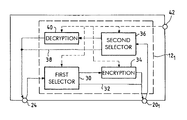
- FIG. 2 is a diagram of an encryption and decryption device according to the invention.
- FIG. 3 shows one application of the device shown in FIG. 2 .
- FIG. 4 shows a variant use of the device shown in FIG. 2 .
- FIG. 5 is a diagram showing a packet encrypted by the FIG. 2 device.
- FIG. 6 shows one example of exchanging security messages.
- FIG. 7 is a diagram analogous to that of FIG. 6 , for another phase of exchanging messages.
- FIG. 8 is also a diagram analogous to that of FIG. 6 , for a further phase of exchanging messages.
- IP Internet Protocol
- the satellite telecommunication network includes terrestrial terminals 12 , 14 , 16 , 18 , etc. for sending and receiving in accordance with the Internet Protocol.
- the packets sent and received pass through receiver and retransmitter equipment units on board a satellite 20 of any geostationary or non-geostationary type.
- the packets, sent by each terminal 12 are single-destination or multidestination packets.
- the term “single-destination” refers to the fact that a terminal sends a message to only one other terminal.
- the term “multidestination” refers to the fact that a terminal sends a message to a plurality of other terminals. Some multidestination communication is not addressed to all the terminals in the coverage area of the satellite, but only to terminals within the same group. Data addressed to selected terminals is therefore encrypted.
- each terminal 12 , 14 , etc. is allocated an encryption and decryption unit 12 1 , 14 1 , etc., which can take the form of a unit separate from the terminal 12 , as shown here.
- the encryption and decryption units are integrated into the satellite terminal software (this is not shown in FIG. 1 ).
- the encryption and decryption mechanisms and the other functions of the units 12 1 , 14 1 , etc. can in this case be integrated into the IP stack of the terminals 12 , 14 .
- the following description refers mainly to the situation shown, i.e. that in which encryption and decryption units 12 1 , 14 1 , etc. are separate from the terminals 12 , 14 , etc.
- the units 12 1 , 14 1 are managed by a master unit 16 1 (server) whose function is to authenticate the units 12 1 , 14 1 , 16 1 , 18 1 , etc., referred to as client units, and to distribute to them all the information they need relating to the security level decided on for the transmission of data for the group comprising the associated terminals and units, i.e. all of the information needed for data supplied by one member of the group to be understandable only to other members of the group.
- a master unit 16 1 server
- client units i.e. all of the information needed for data supplied by one member of the group to be understandable only to other members of the group.
- the set of parameters to be supplied to each unit is referred to as a “security association” and the parameters are distributed to each new unit after verifying its identity.
- the IP packets sent by one member of the group are encrypted by the unit 12 1 , 14 1 , etc. where they enter the satellite communication network 20 .
- the packets can be received by all of the terminals in the field of the satellite, but can be decrypted only by the various other members of the group, using their corresponding units.
- Transmission in the satellite network can be in tunnel mode, in which an IP packet containing data and a header is encrypted in its entirety and the encrypted packet forms the data portion of a new packet, to which a header is added.
- the exact type of processing that is applied to the packet is described in the security association. It is possible not only to encrypt the packet in its entirety but also to modify the IP fields.
- the invention can use a satellite transmission network architecture without modifying it.
- FIG. 2 is a block diagram showing the structure of the unit 12 1 .
- the unit includes a first selector 30 which receives data from the terrestrial network 24 and supplies the data either directly to the satellite network 20 1 (via connection 32 ) if there is no encryption or via an encryption unit 34 .
- the unit 12 1 includes a second selector 36 receiving data from the satellite network 20 1 and supplying data to the terrestrial network 24 either directly via the connection 38 or via a decryption unit 40 .
- the selectors 30 and 36 , the encryption unit 34 and the decryption unit 40 receive control data from a command or control plane 42 .
- FIG. 3 shows an embodiment in which the protocols used by the units 12 1 , 14 1 , etc. are Ethernet protocols (eth 0 , eth 1 ), transmission occurring in the physical layer, i.e. at the level of an Ethernet frame, without ascending to the IP layer.
- Ethernet protocols eth 0 , eth 1
- Ethernet frames are captured by the client units and the packets are extracted from them, possibly encrypted, as explained above, and then reintroduced into the frame before they are transmitted to the satellite network 20 1 .
- Frames coming from the network 20 1 are subjected to the opposite processing, after verifying their integrity.
- Each client unit has a specific IP address that is used to communicate with the master unit and to authenticate it to the master unit so that it can receive the security association parameters.
- the IP address is also useful for renewing keys.
- FIG. 4 shows the encryption and decryption unit when it consists of software in the satellite terminal.
- the data coming from the satellite network is supplied to an interface module 50 which transmits the data to a module 52 for de-encapsulating IP packets.
- the de-encapsulated IP packets are supplied to a unit 54 containing selector and decryption modules having the same function as the units described with reference to FIG. 2 .
- the data from the block 54 is supplied to the IP layer 56 via an interface 58 with the IP layer.
- the data from the IP layer is transmitted to the terrestrial network, routed with the aid of interfaces 60 1 , 60 2 and transmitted to respective interfaces 62 1 , 62 2 .
- the interfaces are bidirectional, of course.
- the client and master units firstly protect and secure IP communications.
- the confidentiality of the traffic is assured by encrypting the data and the headers of the IP packets and by using tunnel mode transmission in the satellite network 20 1 .
- Each client unit includes means for verifying the integrity of the data, i.e. for verifying if each IP packet received has been modified, whether accidentally or intentionally.
- Each client unit can also authenticate the source of the data, i.e. verify that each IP packet comes from a member of the group.
- each packet is assigned a unique integer sequence number.
- the replayed packet will have a number that does not match the other packets.
- the master unit 16 1 includes means for authenticating units.
- the master unit provides centralized management of the keys used by each client unit to secure IP traffic.
- the master unit generates, distributes and renews keys.
- the master unit and the client units can be organized so that a plurality of security levels can be defined in the same group. For example, if a user group comprises all the members of a company, it is possible to distinguish head office staff from the staff of each subsidiary, characterized by their network addresses.
- the data protection services namely the traffic confidentiality service, the data source authentication service, and the data integrity verification service, can be used separately or in combination.
- the traffic confidentiality service without verifying the authenticity of the data source or the integrity of the data.
- the traffic confidentiality service is combined with authentication of the data and/or verification of the data integrity.
- the data source can be authenticated and/or the data integrity verified without providing the traffic confidentiality service.
- a control plane is defined for controlling the data that includes means in each master unit and in each client unit.
- the master unit constitutes a central server for managing the client units and includes a database of client units authorized to access data that must be exchanged within the group.
- Each client unit is listed in the database with a unique logical identifier and a secret data item which is known only to the master unit and the client unit concerned and is used for authentication.
- the database also includes a list of identifiers of security associations that each client unit is authorized to access.
- the main parameters of the security association database are:
- each client unit includes a memory card, for example a microprocessor card, whose memory contains the logical identifier of the unit, the secret key shared only with the master unit, an IP address and a parameter defining the unit as a network element.
- a memory card for example a microprocessor card, whose memory contains the logical identifier of the unit, the secret key shared only with the master unit, an IP address and a parameter defining the unit as a network element.
- phase 1 Before a client unit is authorized to receive and send IP packets in a secure manner, a connection is set up between the client unit and the master unit in order to start a preliminary authorization session referred to as phase 1 ( FIG. 6 ), after which the master unit sends configuration information in single-destination mode (phase 2 — FIG. 7 ) and/or in multidestination mode (phase 2 a — FIG. 8 ). This information is exchanged via the satellite network.
- the client unit and the master unit authenticate each other, for example using a shared key.
- the master unit can verify the identity of the client unit and determine if it is authorized to access the security associations of the group to which it belongs and the client unit can verify that it is really dealing with the master unit.
- a secret common key is generated, for example a Diffie-Hellman key, and is then used for secure transmission of the tables or parameters of the security association of the group.
- the first phase of the IETF standard Internet Key Exchange (IKE) can be used for phase 1 , either in principal mode (as shown in FIG. 6 ) or in aggressive mode.
- IKE Internet Key Exchange
- the parameters can be transmitted not only by single-destination messages (phase 2 — FIG. 7 ), but also by multidestination messages (phase 2 a — FIG. 8 ).
- the master unit sends to a plurality of common units belonging to the same group.
- This phase is protected by the control security association. It can be used to configure client units or to update their security associations.
- This phase can be used if numerous client units of the same group set up a connection to the master unit at the same time.
- the master unit can send in single-destination mode only the control security association for each client unit and can afterward transmit the security association tables to which they have right of access simultaneously to all the client units.
- This multidestination transmission optimizes bandwidth. It can also be used after single-destination transmission to harmonize the security associations of the client units so that the latter are updated at the same time.
- phase 1 in the principal mode or the aggressive mode, the session keys used for encryption and decryption, authentication and verification of the integrity of the IP packets by the client units are therefore distributed by the master unit and then regularly renewed. Either a nominal mode or a degraded mode is used to distribute and renew keys.
- the nominal mode is particularly suitable if the number of units is large.
- the data plane includes the IP packet format, the headers of the various packet types, and the functions and algorithms used.
- FIG. 5 shows a conventional IP packet which includes a data portion 70 and an IP header portion 72 .
- the tunnel mode is used in which a new IP packet is created from the original packet and the original packet is secured, i.e. its header and its data are encrypted.
- the packet 70 , 72 is encrypted to form the packet 74 to which are added an IP′ header 76 for addressing and routing and an IPSec header 78 for securing the data to be transmitted and which is also needed to decrypt it.
- Transmission can be in pure tunnel mode, in which case the source IP address of the new IP packet is the IP address of the sender unit and the destination IP address is that of the destination unit(s). In other words, the IP addresses of the original source and the final addressee can be hidden in this case.
- the IPSec header 78 dedicated to the security mechanisms and functions applied to the original IP packet can include one or more of the following fields:
- the encryption algorithm is applied to the original IP packet, i.e. to the headers and the data.
- the hashing functions are applied to the whole of the packet, i.e. to the IP′ header, to the IPSec header and to the secure data. In this way it is possible to detect any modification to the parameters referred to in clear that are essential for the receiver to be able to decrypt the packets, to carry out the various verifications, and to reassemble the original packet.
- the encapsulation of the IP packets depends on the security associations defined for the packet traffic. It is therefore possible to use the encapsulation defined above, the standard IPSec AH/ESP encapsulations, or an IP in IP encapsulation. It is also possible to modify the IP packet, which can be sent without encapsulation.
- the invention provides a simple way to secure multidestination or single-destination data transmitted in accordance with the IP protocol by a radio system, for example, and more particularly by a satellite system. It is suitable for virtual private networks (VPN).
- VPN virtual private networks
- the various session set-up phases are made reliable to assure that all of the configurations sent by the master unit are implemented in the destination units and to assure that key renewals and updates are applied in all of the client units.
- phase 1 ( FIG. 6 ), during which messages are exchanged in a predetermined order, reliability is assured by imposing the following constraints: only one message is sent at a time; the order of the messages is fixed, and each sending is associated with a time-delay: if the next message is not received before the end of the time-delay the message is transmitted again.
- FIG. 6 is a diagram showing one example of the exchange of messages for phase 1 between a master unit and a client unit.
- the figure shows six messages for mutual authentication of the master unit and the client unit and setting up an encrypted tunnel.
- these messages use the IKE protocol, to be more precise the Request for Comments (RFC) 2408 standard protocol Internet Security Association and Key Management Protocol (ISAKMP).
- RRC Request for Comments
- ISAKMP Internet Security Association and Key Management Protocol
- HDR is a generic header followed by data.
- SA is a security association
- T is a transformation
- KE is an exchange of keys.
- NONCE is a random value.
- HASH is a hashing value.
- IDi is an identifier
- SEQ is a sequence number.
- SIG is a digital signature
- HDR* signifies that all of the data of the message is encrypted.
- phase 2 the server sends each client unit configuration messages in single-destination mode.
- the number of configuration messages varies according to the session.
- an acknowledgement procedure is provided, based on a sequence number present in one of the fields of the message, and unacknowledged messages are retransmitted.
- the acknowledgements are selective: the receiver specifies the sequence number of messages already received.
- the client unit periodically sends an acknowledgement message indicating the sequence number up to which it has received all messages. For example, if the client unit has received correctly the sequence numbers from 1 to 9 and from 11 to 15 , it sends an acknowledgement mentioning this and the master unit knows that it must send the message corresponding to the missing sequence number 10 again. This being so, because the acknowledgement comes when other messages have already reached the client unit, selective acknowledgement limits the resending of messages to those that have not been received. As for the first phase, any message that is not acknowledged during its time-delay is transmitted again.
- Phase 2 constitutes a phase of updating the client units relative to the units already connected and provides instructions for encrypting packets.
- the ISAKMP protocol is used, with the same formalism.
- lines 1 , 2 and 6 carry an indication SA/P/T IPSec that corresponds to the sending of data specific to the invention.
- the part of the data in lines 1 and 2 contains n 1 Param and n 2 Param which signify “n 1 parameters” and “n 2 parameters”, and these parameters correspond to those of functional units in each security association (see below).
- Line 6 includes control parameters.
- the suffix ack for example as in SEQ_ack, means an SEQ (sequence number) acknowledgement.
- phase 2 a the master unit sends multidestination configuration messages to a plurality of client units.
- a negative acknowledgement with retransmission is used, i.e. a client unit that has not received a message asks for it to be transmitted again by sending a negative acknowledgement message.
- Each client unit knows the first sequence number that the master unit will use and the master unit regularly sends a message indicating the last sequence number it has used. If a client unit finds that it has not received one or more messages it starts a time-delay. At the end of this time-delay the client unit sends a negative acknowledgement message indicating the missing sequence numbers, which instigates retransmission of the corresponding messages in multidestination mode.
- the time-delay can be different from one client unit to another.
- FIG. 8 shows an example of messages sent by the master unit in multidestination mode and a message (line 5 ) sent by one of the client units to the master unit.
- each line has the same meaning as in FIGS. 6 and 7 .
- the suffix Nack corresponds to a negative acknowledgement (see above)
- HDR** signifies that the encryption of all of the data of the message corresponds to another key and/or an encryption algorithm different from that used for phase 1 or phase 2 ( FIGS. 6 and 7 ).
- the secure protocol offers additional functions and services compared to the standard IPSec protocol.
- IPSec protocol In the prior art IPSec protocol, a security association is used only to define the parameters used to secure IPSec packets. Thus the IPSec protocol constitutes a single functional unit for protecting streams of data. No parameter can be modified during the use of this unit, except for the keys, which are renewed regularly. If the user wishes to modify a characteristic of the security association, it must be renegotiated.
- supplementary services are defined in each security association and constitute separate functional units that are strung together.
- the functional units that can be included in each security association constitute the following group, for example: the ESP IPSec encryption protocol (defined by the standard RFC 2406), the AH IPSec authentication protocol (defined by the RFC 2402 standard), encryption, authentication, tunnel mode, a “spoofer” TCP protocol (modifications of TCP packets that prevent bit rate limitations associated with the satellite transmission time), a proxy IGMP protocol (modification of Internet Group Management Protocol (IGMP) packets to optimize traffic on the satellite link), and a Drop protocol (filter based on a description of packets and passing only packets having an authorized template).
- the ESP IPSec encryption protocol defined by the standard RFC 2406
- the AH IPSec authentication protocol defined by the RFC 2402 standard
- encryption authentication
- authentication tunnel mode
- a “spoofer” TCP protocol modifications of TCP packets that prevent bit rate limitations associated with the satellite transmission time
- a proxy IGMP protocol modification of Internet Group Management Protocol (IGMP) packets to optimize traffic on
- the stringing of the functional units makes the protocol flexible. Thus during the use of a security association it is possible to modify the parameters of the string by eliminating a unit, adding a unit, or replacing one unit with another.
Abstract
Description
-
- filtering parameters, defining the addressee group,
- parameters of security association functions, namely:
- the type of security association that defines the IP packet encapsulation format,
- transmission in pure tunnel mode or in transport tunnel mode with the IP address of the addressee(s) (according to whether transmission is single-destination or multidestination),
- an authentication function that includes the following options: no authentication, an Keyed-Hash Method Authentication Code Secure Hash Algorithm 1 (HMAC-SHA1), HMAC-Response Desired 5 (RD5), etc. function; the parameters of the authentication function are the key to be used and the length and service life of the key,
- the encryption function, which can include the following options: no encryption, Triple Data Encryption Standard Electronic Code Book (3DESECB), Triple Data Encryption Standard Cipher-Block Chaining (3DESCBC), etc.; the encryption function also includes as parameters the key to be used, its length and its service life, and
- the expiry date of the security association, which is linked to the service life of the keys, of course.
-
- The principal mode carries out mutual authentication by means of shared keys and generates a secret common key.
- The aggressive mode also carries mutual authentication using shared keys and generates a secret common key. In the aggressive mode,
phase 1 is carried out faster than in the principal mode. The aggressive mode does not protect the identities of the master and client units.
-
- The control security association, which is common to all of the client units and received in phase 2 (
FIG. 7 ), is used for key renewal in nominal mode. The control security association protects the session keys. During session key renewal, the master unit can send all authorized client units simultaneously the new keys encrypted with the encryption key of the control security association.
- The control security association, which is common to all of the client units and received in phase 2 (
-
- In degraded mode, the session keys are sent to each client unit and are protected for each client unit by the secure tunnel to the master unit set up in phase 1 (
FIG. 6 ). The degraded mode therefore uses one by one transmission. It differs from the nominal mode in that it does not use the control security association.
- In degraded mode, the session keys are sent to each client unit and are protected for each client unit by the secure tunnel to the master unit set up in phase 1 (
-
- An identifier of the security association applied to the packet. This field enables each unit to identify, for a received IP packet, the functions and the keys to be used to return it to its original form.
- An authentication field that supplies a value resulting from the application of a hashing function to the
packet - A parameter indicating the length of the packet and if it was segmented before it was transmitted in tunnel mode. In this case, the parameter indicates if the segment is the first or last segment or an intermediate segment. This field enables the receiving unit to assemble the original packet.
- The service life of the security association with its start and end dates. This field indicates if a new session key is being used or if the current key is reaching the end of its life.
- A counter that is incremented for each IP packet sent. The number allocated to each packet in this way prevents replaying. If a plurality of sources are adapted to send IP packets, each source has its own counter and the receivers can then identify the source of the IP packet with the source IP address.
- The functions and algorithms used are, for example, those of the IPSec standard protocol, i.e. the CBC mode 3DES protocol for encrypting the data and hashing functions such as the HMAC-Message Digest Algorithm 5 (MD5) function or the HMAC-SHA function for verifying the integrity, authenticity and source of a packet.
Claims (35)
Applications Claiming Priority (2)
| Application Number | Priority Date | Filing Date | Title |
|---|---|---|---|
| FR0204088 | 2002-04-02 | ||
| FR0204088A FR2838008B1 (en) | 2002-04-02 | 2002-04-02 | TELECOMMUNICATION SYSTEM, PARTICULARLY IP TYPE, AND EQUIPMENT FOR SUCH A SYSTEM |
Publications (2)
| Publication Number | Publication Date |
|---|---|
| US20030188159A1 US20030188159A1 (en) | 2003-10-02 |
| US7991993B2 true US7991993B2 (en) | 2011-08-02 |
Family
ID=27839393
Family Applications (1)
| Application Number | Title | Priority Date | Filing Date |
|---|---|---|---|
| US10/403,083 Active 2026-07-21 US7991993B2 (en) | 2002-04-02 | 2003-04-01 | Telecommunication system, for example an IP telecommunication system, and equipment units for use in the system |
Country Status (7)
| Country | Link |
|---|---|
| US (1) | US7991993B2 (en) |
| EP (1) | EP1351440B1 (en) |
| AT (1) | ATE333736T1 (en) |
| CA (1) | CA2423024C (en) |
| DE (1) | DE60306835T2 (en) |
| FR (1) | FR2838008B1 (en) |
| IL (1) | IL155108A0 (en) |
Cited By (4)
| Publication number | Priority date | Publication date | Assignee | Title |
|---|---|---|---|---|
| US8850200B1 (en) * | 2011-06-21 | 2014-09-30 | Synectic Design, LLC | Method and apparatus for secure communications through a trusted intermediary server |
| US10848442B2 (en) * | 2017-08-18 | 2020-11-24 | Missing Link Electronics, Inc. | Heterogeneous packet-based transport |
| US11528601B1 (en) | 2021-06-09 | 2022-12-13 | T-Mobile Usa, Inc. | Determining and ameliorating wireless telecommunication network functionalities that are impaired when using end-to-end encryption |
| US11695708B2 (en) | 2017-08-18 | 2023-07-04 | Missing Link Electronics, Inc. | Deterministic real time multi protocol heterogeneous packet based transport |
Families Citing this family (30)
| Publication number | Priority date | Publication date | Assignee | Title |
|---|---|---|---|---|
| FR2854522B1 (en) * | 2003-04-30 | 2005-09-30 | Cit Alcatel | DEVICE FOR PROCESSING DATA PACKET INTETS FOR TWO LEVEL SWITCHING VIA A LOGIC BUS WITHIN A SATELLITE COMMUNICATIONS NETWORK. |
| US20050041808A1 (en) * | 2003-08-22 | 2005-02-24 | Nortel Networks Limited | Method and apparatus for facilitating roaming between wireless domains |
| US7620041B2 (en) * | 2004-04-15 | 2009-11-17 | Alcatel-Lucent Usa Inc. | Authentication mechanisms for call control message integrity and origin verification |
| US8036221B2 (en) | 2004-06-14 | 2011-10-11 | Cisco Technology, Inc. | Method and system for dynamic secured group communication |
| US7509491B1 (en) * | 2004-06-14 | 2009-03-24 | Cisco Technology, Inc. | System and method for dynamic secured group communication |
| JP2006033275A (en) * | 2004-07-14 | 2006-02-02 | Fujitsu Ltd | Loop frame detector and loop frame detection method |
| US7238619B2 (en) * | 2005-07-06 | 2007-07-03 | United Microelectronics Corp. | Method for eliminating bridging defect in via first dual damascene process |
| US7720995B2 (en) * | 2007-06-08 | 2010-05-18 | Cisco Technology, Inc. | Conditional BGP advertising for dynamic group VPN (DGVPN) clients |
| US9294506B2 (en) * | 2010-05-17 | 2016-03-22 | Certes Networks, Inc. | Method and apparatus for security encapsulating IP datagrams |
| FR2965995B1 (en) * | 2010-10-12 | 2012-12-14 | Thales Sa | METHOD AND SYSTEM FOR DYNAMICALLY SETTING DIGITAL TUNNELS ON BANDRATED NETWORKS |
| US10341311B2 (en) * | 2015-07-20 | 2019-07-02 | Schweitzer Engineering Laboratories, Inc. | Communication device for implementing selective encryption in a software defined network |
| US10659314B2 (en) | 2015-07-20 | 2020-05-19 | Schweitzer Engineering Laboratories, Inc. | Communication host profiles |
| US9923779B2 (en) | 2015-07-20 | 2018-03-20 | Schweitzer Engineering Laboratories, Inc. | Configuration of a software defined network |
| US9900206B2 (en) | 2015-07-20 | 2018-02-20 | Schweitzer Engineering Laboratories, Inc. | Communication device with persistent configuration and verification |
| US9769060B2 (en) | 2015-07-20 | 2017-09-19 | Schweitzer Engineering Laboratories, Inc. | Simulating, visualizing, and searching traffic in a software defined network |
| US9686125B2 (en) | 2015-07-20 | 2017-06-20 | Schwetizer Engineering Laboratories, Inc. | Network reliability assessment |
| US9866483B2 (en) | 2015-07-20 | 2018-01-09 | Schweitzer Engineering Laboratories, Inc. | Routing of traffic in network through automatically generated and physically distinct communication paths |
| US10863558B2 (en) | 2016-03-30 | 2020-12-08 | Schweitzer Engineering Laboratories, Inc. | Communication device for implementing trusted relationships in a software defined network |
| US10033709B1 (en) * | 2017-11-20 | 2018-07-24 | Microsoft Technology Licensing, Llc | Method and apparatus for improving privacy of communications through channels having excess capacity |
| US10785189B2 (en) | 2018-03-01 | 2020-09-22 | Schweitzer Engineering Laboratories, Inc. | Selective port mirroring and in-band transport of network communications for inspection |
| US11075908B2 (en) | 2019-05-17 | 2021-07-27 | Schweitzer Engineering Laboratories, Inc. | Authentication in a software defined network |
| US10979309B2 (en) | 2019-08-07 | 2021-04-13 | Schweitzer Engineering Laboratories, Inc. | Automated convergence of physical design and configuration of software defined network |
| US11228521B2 (en) | 2019-11-04 | 2022-01-18 | Schweitzer Engineering Laboratories, Inc. | Systems and method for detecting failover capability of a network device |
| US11165685B2 (en) | 2019-12-20 | 2021-11-02 | Schweitzer Engineering Laboratories, Inc. | Multipoint redundant network device path planning for programmable networks |
| US11431605B2 (en) | 2020-12-16 | 2022-08-30 | Schweitzer Engineering Laboratories, Inc. | Communication system tester and related methods |
| US11418432B1 (en) | 2021-04-22 | 2022-08-16 | Schweitzer Engineering Laboratories, Inc. | Automated communication flow discovery and configuration in a software defined network |
| US11750502B2 (en) | 2021-09-01 | 2023-09-05 | Schweitzer Engineering Laboratories, Inc. | Detection of in-band software defined network controllers using parallel redundancy protocol |
| US11336564B1 (en) | 2021-09-01 | 2022-05-17 | Schweitzer Engineering Laboratories, Inc. | Detection of active hosts using parallel redundancy protocol in software defined networks |
| US11838174B2 (en) | 2022-02-24 | 2023-12-05 | Schweitzer Engineering Laboratories, Inc. | Multicast fast failover handling |
| US11848860B2 (en) | 2022-02-24 | 2023-12-19 | Schweitzer Engineering Laboratories, Inc. | Multicast fast failover turnaround overlap handling |
Citations (10)
| Publication number | Priority date | Publication date | Assignee | Title |
|---|---|---|---|---|
| WO1999009707A1 (en) | 1997-08-18 | 1999-02-25 | Mci Communications Corporation | Multicast transmission of information over a satellite |
| US6073235A (en) * | 1997-06-24 | 2000-06-06 | At&T Corp. | Private broadcast communication system and method for private broadcast communication over a wired or wireless network |
| US6178453B1 (en) * | 1997-02-18 | 2001-01-23 | Netspeak Corporation | Virtual circuit switching architecture |
| US6195751B1 (en) * | 1998-01-20 | 2001-02-27 | Sun Microsystems, Inc. | Efficient, secure multicasting with minimal knowledge |
| US6215877B1 (en) * | 1998-03-20 | 2001-04-10 | Fujitsu Limited | Key management server, chat system terminal unit, chat system and recording medium |
| WO2002011356A2 (en) | 2000-08-01 | 2002-02-07 | Deutsche Telekom Ag | Method of key exchange for a cryptographic secure point to multipoint connection |
| US20020069369A1 (en) * | 2000-07-05 | 2002-06-06 | Tremain Geoffrey Donald | Method and apparatus for providing computer services |
| US6606706B1 (en) * | 1999-02-08 | 2003-08-12 | Nortel Networks Limited | Hierarchical multicast traffic security system in an internetwork |
| US20030163690A1 (en) * | 2002-02-26 | 2003-08-28 | Stewart Ian A. | Method for secure multicast repeating on the public Internet |
| US6629243B1 (en) * | 1998-10-07 | 2003-09-30 | Nds Limited | Secure communications system |
-
2002
- 2002-04-02 FR FR0204088A patent/FR2838008B1/en not_active Expired - Fee Related
-
2003
- 2003-03-21 EP EP03290722A patent/EP1351440B1/en not_active Expired - Lifetime
- 2003-03-21 AT AT03290722T patent/ATE333736T1/en not_active IP Right Cessation
- 2003-03-21 DE DE60306835T patent/DE60306835T2/en not_active Expired - Lifetime
- 2003-03-26 CA CA2423024A patent/CA2423024C/en not_active Expired - Fee Related
- 2003-03-27 IL IL15510803A patent/IL155108A0/en unknown
- 2003-04-01 US US10/403,083 patent/US7991993B2/en active Active
Patent Citations (10)
| Publication number | Priority date | Publication date | Assignee | Title |
|---|---|---|---|---|
| US6178453B1 (en) * | 1997-02-18 | 2001-01-23 | Netspeak Corporation | Virtual circuit switching architecture |
| US6073235A (en) * | 1997-06-24 | 2000-06-06 | At&T Corp. | Private broadcast communication system and method for private broadcast communication over a wired or wireless network |
| WO1999009707A1 (en) | 1997-08-18 | 1999-02-25 | Mci Communications Corporation | Multicast transmission of information over a satellite |
| US6195751B1 (en) * | 1998-01-20 | 2001-02-27 | Sun Microsystems, Inc. | Efficient, secure multicasting with minimal knowledge |
| US6215877B1 (en) * | 1998-03-20 | 2001-04-10 | Fujitsu Limited | Key management server, chat system terminal unit, chat system and recording medium |
| US6629243B1 (en) * | 1998-10-07 | 2003-09-30 | Nds Limited | Secure communications system |
| US6606706B1 (en) * | 1999-02-08 | 2003-08-12 | Nortel Networks Limited | Hierarchical multicast traffic security system in an internetwork |
| US20020069369A1 (en) * | 2000-07-05 | 2002-06-06 | Tremain Geoffrey Donald | Method and apparatus for providing computer services |
| WO2002011356A2 (en) | 2000-08-01 | 2002-02-07 | Deutsche Telekom Ag | Method of key exchange for a cryptographic secure point to multipoint connection |
| US20030163690A1 (en) * | 2002-02-26 | 2003-08-28 | Stewart Ian A. | Method for secure multicast repeating on the public Internet |
Non-Patent Citations (2)
| Title |
|---|
| Andrew S. Tanenbaum, "Computer Networks", 1996, Computer Networks, Englewood Cliffs, Prentice Hall, US pp. 212-239, XP002079137. |
| F. Jordan et al, "Secure Multicast Communications Using a Key Distribution Center", Information Networks and Data Communication. Proceedings of the IFIP TC6 International Conference on Information Networks and Data Communication, Funchal, Madeira Island, Portugal, Apr. 18-21, 1994, Proceedings of the IFIP TC6 International Conference, vol. CONF. 5, Apr. 18, 1994, pp. 367-380, XP000593303. |
Cited By (5)
| Publication number | Priority date | Publication date | Assignee | Title |
|---|---|---|---|---|
| US8850200B1 (en) * | 2011-06-21 | 2014-09-30 | Synectic Design, LLC | Method and apparatus for secure communications through a trusted intermediary server |
| US10848442B2 (en) * | 2017-08-18 | 2020-11-24 | Missing Link Electronics, Inc. | Heterogeneous packet-based transport |
| US11695708B2 (en) | 2017-08-18 | 2023-07-04 | Missing Link Electronics, Inc. | Deterministic real time multi protocol heterogeneous packet based transport |
| US11528601B1 (en) | 2021-06-09 | 2022-12-13 | T-Mobile Usa, Inc. | Determining and ameliorating wireless telecommunication network functionalities that are impaired when using end-to-end encryption |
| US11706615B2 (en) | 2021-06-09 | 2023-07-18 | T-Mobile Usa, Inc. | Determining and ameliorating wireless telecommunication network functionalities that are impaired when using end-to-end encryption |
Also Published As
| Publication number | Publication date |
|---|---|
| FR2838008B1 (en) | 2004-08-27 |
| CA2423024A1 (en) | 2003-10-02 |
| ATE333736T1 (en) | 2006-08-15 |
| FR2838008A1 (en) | 2003-10-03 |
| DE60306835D1 (en) | 2006-08-31 |
| CA2423024C (en) | 2012-05-29 |
| EP1351440A1 (en) | 2003-10-08 |
| US20030188159A1 (en) | 2003-10-02 |
| EP1351440B1 (en) | 2006-07-19 |
| IL155108A0 (en) | 2003-10-31 |
| DE60306835T2 (en) | 2007-02-15 |
Similar Documents
| Publication | Publication Date | Title |
|---|---|---|
| US7991993B2 (en) | Telecommunication system, for example an IP telecommunication system, and equipment units for use in the system | |
| US6782474B1 (en) | Network connectable device and method for its installation and configuration | |
| KR100782865B1 (en) | Data transmission controlling method and data transmission system | |
| US7571463B1 (en) | Method an apparatus for providing a scalable and secure network without point to point associations | |
| USRE39589E1 (en) | Security method for transmissions in telecommunication networks | |
| US7925026B2 (en) | Systems and methods for providing autonomous security | |
| US20080083011A1 (en) | Protocol/API between a key server (KAP) and an enforcement point (PEP) | |
| EP0951767A2 (en) | Improved network security device | |
| JP4877932B2 (en) | ENCRYPTED COMMUNICATION SYSTEM AND ENCRYPTION KEY UPDATE METHOD | |
| Moreira et al. | Security mechanisms to protect IEEE 1588 synchronization: State of the art and trends | |
| CN114172745A (en) | Internet of things security protocol system | |
| CN113904809B (en) | Communication method, device, electronic equipment and storage medium | |
| US20120163383A1 (en) | Method and device for transmitting data between two secured ethernet-type networks through a routed network | |
| US8447033B2 (en) | Method for protecting broadcast frame | |
| US20080104693A1 (en) | Transporting keys between security protocols | |
| CN110943996B (en) | Management method, device and system for business encryption and decryption | |
| WO2008042318A2 (en) | Systems and methods for management of secured networks with distributed keys | |
| CN108111515B (en) | End-to-end secure communication encryption method suitable for satellite communication | |
| CN115567192A (en) | Method and system for realizing transparent encryption and decryption of multicast data by quantum key distribution | |
| Hohendorf et al. | Secure End-to-End Transport Over SCTP. | |
| CN210839642U (en) | Device for safely receiving and sending terminal data of Internet of things | |
| Cisco | Introduction to Cisco IPsec Technology | |
| Salam et al. | DVB-RCS security framework for ULE-based encapsulation | |
| CN116389169B (en) | Method for avoiding disorder and fragmentation of data packets of national security IPSecVPN gateway | |
| CN111130756B (en) | Node routing safety management and control system |
Legal Events
| Date | Code | Title | Description |
|---|---|---|---|
| AS | Assignment |
Owner name: ALCATEL, FRANCE Free format text: ASSIGNMENT OF ASSIGNORS INTEREST;ASSIGNORS:JOSSET, SEBASTIEN;DUQUERROY, LAURENCE;REEL/FRAME:013929/0527 Effective date: 20030108 |
|
| FEPP | Fee payment procedure |
Free format text: PAYOR NUMBER ASSIGNED (ORIGINAL EVENT CODE: ASPN); ENTITY STATUS OF PATENT OWNER: LARGE ENTITY Free format text: PAYER NUMBER DE-ASSIGNED (ORIGINAL EVENT CODE: RMPN); ENTITY STATUS OF PATENT OWNER: LARGE ENTITY |
|
| AS | Assignment |
Owner name: ALCATEL LUCENT, FRANCE Free format text: CHANGE OF NAME;ASSIGNOR:ALCATEL;REEL/FRAME:026304/0539 Effective date: 20061130 |
|
| STCF | Information on status: patent grant |
Free format text: PATENTED CASE |
|
| AS | Assignment |
Owner name: CREDIT SUISSE AG, NEW YORK Free format text: SECURITY AGREEMENT;ASSIGNOR:LUCENT, ALCATEL;REEL/FRAME:029821/0001 Effective date: 20130130 Owner name: CREDIT SUISSE AG, NEW YORK Free format text: SECURITY AGREEMENT;ASSIGNOR:ALCATEL LUCENT;REEL/FRAME:029821/0001 Effective date: 20130130 |
|
| AS | Assignment |
Owner name: ALCATEL LUCENT, FRANCE Free format text: RELEASE BY SECURED PARTY;ASSIGNOR:CREDIT SUISSE AG;REEL/FRAME:033868/0001 Effective date: 20140819 |
|
| FPAY | Fee payment |
Year of fee payment: 4 |
|
| AS | Assignment |
Owner name: OMEGA CREDIT OPPORTUNITIES MASTER FUND, LP, NEW YORK Free format text: SECURITY INTEREST;ASSIGNOR:WSOU INVESTMENTS, LLC;REEL/FRAME:043966/0574 Effective date: 20170822 Owner name: OMEGA CREDIT OPPORTUNITIES MASTER FUND, LP, NEW YO Free format text: SECURITY INTEREST;ASSIGNOR:WSOU INVESTMENTS, LLC;REEL/FRAME:043966/0574 Effective date: 20170822 |
|
| AS | Assignment |
Owner name: WSOU INVESTMENTS, LLC, CALIFORNIA Free format text: ASSIGNMENT OF ASSIGNORS INTEREST;ASSIGNOR:ALCATEL LUCENT;REEL/FRAME:044000/0053 Effective date: 20170722 |
|
| FEPP | Fee payment procedure |
Free format text: MAINTENANCE FEE REMINDER MAILED (ORIGINAL EVENT CODE: REM.); ENTITY STATUS OF PATENT OWNER: LARGE ENTITY |
|
| AS | Assignment |
Owner name: BP FUNDING TRUST, SERIES SPL-VI, NEW YORK Free format text: SECURITY INTEREST;ASSIGNOR:WSOU INVESTMENTS, LLC;REEL/FRAME:049235/0068 Effective date: 20190516 |
|
| AS | Assignment |
Owner name: WSOU INVESTMENTS, LLC, CALIFORNIA Free format text: RELEASE BY SECURED PARTY;ASSIGNOR:OCO OPPORTUNITIES MASTER FUND, L.P. (F/K/A OMEGA CREDIT OPPORTUNITIES MASTER FUND LP;REEL/FRAME:049246/0405 Effective date: 20190516 |
|
| FEPP | Fee payment procedure |
Free format text: 7.5 YR SURCHARGE - LATE PMT W/IN 6 MO, LARGE ENTITY (ORIGINAL EVENT CODE: M1555); ENTITY STATUS OF PATENT OWNER: LARGE ENTITY |
|
| MAFP | Maintenance fee payment |
Free format text: PAYMENT OF MAINTENANCE FEE, 8TH YEAR, LARGE ENTITY (ORIGINAL EVENT CODE: M1552); ENTITY STATUS OF PATENT OWNER: LARGE ENTITY Year of fee payment: 8 |
|
| AS | Assignment |
Owner name: OT WSOU TERRIER HOLDINGS, LLC, CALIFORNIA Free format text: SECURITY INTEREST;ASSIGNOR:WSOU INVESTMENTS, LLC;REEL/FRAME:056990/0081 Effective date: 20210528 |
|
| AS | Assignment |
Owner name: WSOU INVESTMENTS, LLC, CALIFORNIA Free format text: RELEASE BY SECURED PARTY;ASSIGNOR:TERRIER SSC, LLC;REEL/FRAME:056526/0093 Effective date: 20210528 |
|
| FEPP | Fee payment procedure |
Free format text: MAINTENANCE FEE REMINDER MAILED (ORIGINAL EVENT CODE: REM.); ENTITY STATUS OF PATENT OWNER: LARGE ENTITY |
|
| FEPP | Fee payment procedure |
Free format text: 11.5 YR SURCHARGE- LATE PMT W/IN 6 MO, LARGE ENTITY (ORIGINAL EVENT CODE: M1556); ENTITY STATUS OF PATENT OWNER: LARGE ENTITY |
|
| MAFP | Maintenance fee payment |
Free format text: PAYMENT OF MAINTENANCE FEE, 12TH YEAR, LARGE ENTITY (ORIGINAL EVENT CODE: M1553); ENTITY STATUS OF PATENT OWNER: LARGE ENTITY Year of fee payment: 12 |