US8015434B2 - Management apparatus, storage system, and storage apparatus management method - Google Patents
Management apparatus, storage system, and storage apparatus management method Download PDFInfo
- Publication number
- US8015434B2 US8015434B2 US12/358,294 US35829409A US8015434B2 US 8015434 B2 US8015434 B2 US 8015434B2 US 35829409 A US35829409 A US 35829409A US 8015434 B2 US8015434 B2 US 8015434B2
- Authority
- US
- United States
- Prior art keywords
- magnetic disk
- disk drive
- identification information
- storage apparatus
- failure
- Prior art date
- Legal status (The legal status is an assumption and is not a legal conclusion. Google has not performed a legal analysis and makes no representation as to the accuracy of the status listed.)
- Active, expires
Links
Images


Classifications
-
- G—PHYSICS
- G06—COMPUTING; CALCULATING OR COUNTING
- G06F—ELECTRIC DIGITAL DATA PROCESSING
- G06F11/00—Error detection; Error correction; Monitoring
- G06F11/07—Responding to the occurrence of a fault, e.g. fault tolerance
- G06F11/0703—Error or fault processing not based on redundancy, i.e. by taking additional measures to deal with the error or fault not making use of redundancy in operation, in hardware, or in data representation
- G06F11/079—Root cause analysis, i.e. error or fault diagnosis
-
- G—PHYSICS
- G06—COMPUTING; CALCULATING OR COUNTING
- G06F—ELECTRIC DIGITAL DATA PROCESSING
- G06F11/00—Error detection; Error correction; Monitoring
- G06F11/07—Responding to the occurrence of a fault, e.g. fault tolerance
- G06F11/0703—Error or fault processing not based on redundancy, i.e. by taking additional measures to deal with the error or fault not making use of redundancy in operation, in hardware, or in data representation
- G06F11/0706—Error or fault processing not based on redundancy, i.e. by taking additional measures to deal with the error or fault not making use of redundancy in operation, in hardware, or in data representation the processing taking place on a specific hardware platform or in a specific software environment
- G06F11/0727—Error or fault processing not based on redundancy, i.e. by taking additional measures to deal with the error or fault not making use of redundancy in operation, in hardware, or in data representation the processing taking place on a specific hardware platform or in a specific software environment in a storage system, e.g. in a DASD or network based storage system
-
- G—PHYSICS
- G06—COMPUTING; CALCULATING OR COUNTING
- G06F—ELECTRIC DIGITAL DATA PROCESSING
- G06F11/00—Error detection; Error correction; Monitoring
- G06F11/07—Responding to the occurrence of a fault, e.g. fault tolerance
- G06F11/16—Error detection or correction of the data by redundancy in hardware
- G06F11/20—Error detection or correction of the data by redundancy in hardware using active fault-masking, e.g. by switching out faulty elements or by switching in spare elements
- G06F11/2053—Error detection or correction of the data by redundancy in hardware using active fault-masking, e.g. by switching out faulty elements or by switching in spare elements where persistent mass storage functionality or persistent mass storage control functionality is redundant
- G06F11/2089—Redundant storage control functionality
Definitions
- the present invention relates to a storage system capable of storing a large volume of data, a management apparatus for managing a storage apparatus, and a storage apparatus management method.
- a storage system provided with a plurality of magnetic disk drives is now used for storing a huge volume of data.
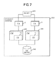
- FIG. 7 is a view schematically illustrating an entire configuration of a conventional storage system.
- a storage system 300 illustrated in FIG. 7 implements a RAID (Redundant Array Independent Disks) configuration for a magnetic disk drive to increase data redundancy so as to provide desirable performance characteristics to a host 200 .
- RAID Redundant Array Independent Disks
- a CA (Channel Adapter) 2 controls the interface with the host 200 .
- the CA 2 Upon reception of data write/read operation request from the host 200 , the CA 2 notifies a CM (Centralized Module) 400 of a processing request.
- the CA 2 directly accesses a cache memory on the CM 400 to perform data transfer between the storage system 300 and host 200 .
- the CM 400 serves as a core of all the modules constituting the storage system 300 .
- the CM 400 performs resource management (manages the resources of each module and executes effective control management). Further, the CM 400 performs cache memory management (manages the allocation of the memory area in the CM 400 and executes general control).
- the CM 400 retains maintenance software and uses the maintenance software to provide various services.
- the CM 400 is provided with a DI (Device Interface) 11 which is a module for performing communication with a DE group 500 (details of which will be described later) composed of a plurality of magnetic disk drives.
- the DI 11 is connected to the DE group 500 by a fiber channel interface (hereinafter, fiber channel is abbreviated as “FC”). Through the DI 11 , the CM 400 performs control of the FC interface communicating with the DE group 500 , I/O control of the magnetic disk drive, control of RAID, and the like.
- FC fiber channel interface
- the storage system 300 has two CAs 2 and two CMs 400 .
- FIG. 8 is a view schematically illustrating a multi-initiator connection between the CMs 400 (DI 11 ) and magnetic disk drives.
- the DIs 11 and magnetic disk drives serving as initiators each are provided with an FC port.
- the respective FC ports are connected to one another to form an arbitrated loop.
- the arbitrated loop is one of fiber channel topologies, in which a plurality of FC ports are connected in a loop so as to allow communication to be performed between a pair of the ports.
- the arbitrated loop supports up to 127 devices.
- AL_PA An address to be uniquely used in the arbitrated loop is assigned to each port in the loop. This address is referred to as AL_PA.
- the values of the AL_PA are not consecutive numbers and therefore the AL_PA is sometimes difficult to handle. For this reason, consecutive numbers are assigned to the respective AL_PA.
- Each of the consecutive numbers is referred to as Loop_ID.
- the value of the AL_PA can be fixed in a device in a hardware manner. However, in the case where the same value is assigned to the AL_PA by accident, AL_PA setting in a device nearer to a Loop Master is prioritized according to the priority set in the loop.
- the Loop Master is a port that leads loop initialization, which is determined at the time of execution of loop initialization. If the loop includes a fabric port, the fabric port becomes the Loop Master. If the loop does not include a fabric port, a port having the smallest WWN (World Wide Name: world wide unique name) (in the present invention, WWPN (World Wide Port Name is referred to as WWN)) value in the loop is selected as the Loop Master.
- WWN World Wide Name: world wide unique name
- WWPN World Wide Port Name
- the loop initialization is a necessary process for recognizing a device connected to the loop so as to make the device operational.
- the loop initialization is executed when a LIP (Loop Initialization Primitive) is issued from the Loop Master onto the loop.
- LIP Loop Initialization Primitive
- the Login is a procedure that exchanges information WWN, etc.) of a target port before data transfer so as to allow the port to be accessed.
- Each FC port carries out the loop initialization when performing communication.
- the AL_PA identification information
- the setting of the AL_PA is made in the connection order of the devices starting from the Loop Master.
- a value to be set to the AL_PA can be specified in a hardware manner (hard assignment), and the specified value is directly set to the AL_PA in most cases.
- the specified AL_PA value is not set but the AL_PA value is set in a software manner (soft assignment) in the subsequent sequence in a predetermined order.
- the order (ascending order or descending order) of the soft assignment is determined based on a predetermined setting. It goes without saying that the same AL_PA value as that has been assigned to an FC port by hard assignment is not permitted.
- the login procedure is executed after the loop initialization, and after the completion of the login procedure, communication with the magnetic disk drive becomes possible.
- FIG. 9 is a view schematically illustrating a relationship between the DEs and magnetic disk drives.
- An apparatus in which the magnetic disk drive is mounted is called DE (Drive Enclosure).
- a plurality of magnetic disk drives can be mounted in one DE.
- the DE according to the present invention can be connected to the arbitrated loop and has a HUB function that allows the magnetic disk drive mounted therein to participate in the loop.
- the DE can be connected to the loop by an FCC (Fiber Channel Controller) incorporated therein and can participate in the loop by the AL_PA assigned thereto.
- FCC Fiber Channel Controller
- the DE group 500 is constituted by a plurality of DEs 3 .
- the DE 3 is provided with two FCCs 31 which are individually connected to respective magnetic disk drives (Disk 32 A, Disk 32 B, . . . , Disk 32 N, which are sometimes collectively referred to as Disk 32 ), so that the two FCCs 31 can refer to the Disk 32 in the same way.
- Disk 32 disk 32 A, Disk 32 B, . . . , Disk 32 N, which are sometimes collectively referred to as Disk 32
- two access paths can be ensured with respect to the respective disk drives 32 .
- the CM 400 can access the Disk 32 using the other side loop.
- the FCC 31 in one DE 3 is cascade-connected to the FCC 31 in another FCC 31 and thereby the plurality of DEs 3 in the DE group 500 are connected to each other.
- the configuration table is a list for storing information concerning the modules constituting the storage system 300 and represents a correspondence between the name of a module and status of the module.
- the content of the configuration table is referred to.
- FIG. 12 is a view schematically illustrating I/O processing of the storage system 300 .
- the CM 400 checks the status of the magnetic disk drive (Disk 32 N) to be accessed by referring to the configuration table before executing I/O processing. When confirming that the magnetic disk drive to be accessed is in normal status on the configuration table, the CM 400 executes the I/O processing for the magnetic disk drive.
- the configuration table is updated every time the status of the module in the storage system 300 is changed. For example, as illustrated in FIG. 13 , in the case where the magnetic disk drive becomes abnormal, the status thereof is updated from normal to abnormal.
- Configuration table update processing will be described with reference to FIG. 14 .
- the magnetic disk drive becomes abnormal, the DI 11 notifies the CM 400 of module status change.
- the CM 400 receives the notification of the module status change and then updates the status of the module on the configuration table. Examples of cases where the module status is to be changed include a case where the CM 400 malfunctions, a case where the DE 3 is removed from a predetermined position in the storage system 300 , a case where the magnetic disk drive has failed and cannot be used, a case where a new magnetic disk drive is added, and the like.
- the CM 400 updates the configuration table when the module status is changed, there exists a time lag between the time at which the DI 11 detects the failure of the magnetic disk drive and the time at which the configuration table on the CM 400 is updated. During this time lag, the CM 400 cannot detect the failure of the magnetic disk drive. It follows that the CM 400 cannot inhibit issuance of I/O but issues I/O even if the magnetic disk drive has failed during the time lag.
- FIG. 15 is a time chart illustrating operations of the host 200 , CM 400 , and DI 11 in the configuration table update processing based on the configuration tables retained in the CM 400 and DI 11 .
- the statuses are differentiated by the width of an arrow, and the time flows downward.
- the DI 11 detects the failure of the Disk 32 N and updates the status of the Disk 32 N on the configuration table retained therein from normal to abnormal.
- the DI 11 notifies the CM 400 that the DI 11 has updated the configuration table retained therein.
- the CM 400 recognizes that the configuration table of the DI 11 has been updated by receiving the notification from the DI 11 and correspondingly updates the configuration table retained in the CM 400 .
- the time lag occurs between the time at which the configuration table retained in the DI 11 is updated and the time at which the update of the configuration table is notified to the CM 400 , and during this time lag, the CM 400 cannot detect the abnormality of the Disk 32 N.
- a disk array device capable of preventing any operation leading to the degeneration of the originally normal disk device. Further, there is disclosed a control method capable of preventing occurrence of a malfunction in an exchanged hard disk drive (HDD) device and detecting a connection miss of the HDD device when an HDD device is exchanged during the operation of a display array device.
- HDD hard disk drive
- a data storage system capable of reducing a load of a data bus for connecting a host system and a data storage system.
- a RAID device capable of preventing, even in the case where a failure which may induce a loop abnormality occurs in a RAID using disks with an FC interface, correcting the loop abnormality so as to prevent data loss.
- Patent Document 1 Japanese Laid-Open Patent Publication No. 2002-108573
- Patent Document 2 Japanese Laid-Open Patent Publication No. 11-85412
- Patent Document 3 Japanese Laid-Open Patent Publication No. 8-263225
- Patent Document 4 Japanese Laid-Open Patent Publication No. 2003-162380
- the storage system 300 When detecting that access to the magnetic disk drive cannot be made, the storage system 300 provided with conventional DEs 3 determines that the magnetic disk drive has failed and logically separates the relevant magnetic disk drive from the storage system 300 .
- the access disabled state can be caused by a failure of the magnetic disk drive itself or by power failure of the DE 3 .
- the AL_PA of the magnetic disk drive provided in the DE 3 disappears from the loop and therefore the magnetic disk drive in the DE 3 becomes invisible to the CM 400 .
- the CM 400 records information indicating that the magnetic disk drive in the DE 3 has become invisible to the CM 400 in the configuration table for update.
- FIGS. 16A to 16C and FIGS. 17A to 17C are views illustrating conventional processing executed in the case where I/O is issued, during the time lag, to the magnetic disk drive (magnetic disk drive in the DE 3 in which a power failure has occurred) provided in the DE 3 which is in a disabled state due to occurrence of a power failure.
- a and B each denote a loop. That is, the storage system 300 has two paths to the DE 3 .
- FIG. 16A illustrates a normal state
- FIG. 16B illustrates a state where a power failure has occurred in the DE 3 .
- the AL_PA of the magnetic disk drive provided in the DE 3 and therefore the magnetic disk drive temporarily disappears (during the power failure) from the loop.
- the reason that the AL_PA disappears is that loop initialization is activated in the case where a power failure has occurred in the DE 3 and, in this case, the value of the AL_PA is not determined.
- the CM 400 When an access request to the magnetic disk drive is generated in this state, the CM 400 tries to access the magnetic disk drive of the DE 3 in which a power failure has occurred through one path (in this case, path A), but the access fails (see FIG. 16C ).
- the CM 400 then tries to access the magnetic disk drive through the other path (in this case, path B), but the access fails (see FIG. 17A ).
- the CM 400 recognizes that the access operation to the magnetic disk drive using all the access paths has failed and determines that the magnetic disk drive to be accessed has failed. At this timing, the CM 400 logically separates the magnetic disk drive from the storage system 300 .
- the magnetic disk drive When the DE 3 is recovered after the resumption of power supply, the magnetic disk drive is accordingly recovered. However, the magnetic disk drive that was determined to be abnormal earlier is still separated from the storage system 300 as one in an access disabled state (see FIG. 17C ). As described above, since the power failure of the DE 3 cannot be detected, the CM 400 has no choice but to determine that the disappearance of the magnetic disk drive in the DE 3 from the loop is caused by a failure of the magnetic disk drive even in the case where a power failure has actually occurred in the DE 3 .
- magnetic disk drive When it has been once determined that the magnetic disk drive has failed as described above, magnetic disk drive is still recognized as failed one even after the resumption of power supply. In order to recover the storage system 300 to a normal state afterward, it is necessary to replace the magnetic disk drive that has been determined to have failed although the magnetic disk drive is actually normal.
- a power failure of the DE 3 occurs and the AL_PA of the magnetic disk drive in the DE 3 in which the power failure has occurred disappears from the loop (step S 101 ).
- the storage system 300 cannot detect the power failure.
- the CM 400 uses a first access path to determine whether the AL_PA of the access target magnetic disk drive exists on the loop (step S 103 : first determination).
- the CM 400 uses a second access path to determine whether the AL_PA of the access target magnetic disk drive exists on the loop (step S 104 : second determination).
- the CM 400 determines that an abnormality has occurred in the magnetic disk drive and updates the configuration table retained therein. It should be noted that the CM 400 updates the status of the magnetic disk drive on the configuration table from normal to abnormal and determines that the failure of the I/O processing for the magnetic disk drive is due to a failure in the magnetic disk drive.
- the CM 400 uses the second access path to perform the I/O processing for the magnetic disk drive without problems (step S 107 ).
- the storage system 300 cannot detect the power failure of the DE 3 , so that when the power failure occurs in the DE 3 , the storage system 300 recognizes as if the magnetic disk drive provided in the DE 3 suddenly disappeared from the loop and, as a result, determines that a failure has occurred in the magnetic disk drive.
- the I/O processing fails. Further, since the magnetic disk drive does not exist on the loop, the CM 400 determines that any failure has occurred in the magnetic disk drive and separates the magnetic disk drive from the storage system 300 . After the DE 3 is recovered from the power failure, the magnetic disk drive, which has not actually failed, appears on the loop. However, since the magnetic disk drive is determined to have failed at the time of occurrence of the power failure, it is not incorporated in the storage system 300 , treated as a failed one, and forced to be replaced with a new one.
- a management apparatus of a storage apparatus including an acquisition determination section that determines whether predetermined identification information can be acquired or not from a mounting apparatus that mounts at least one storage apparatus and has at least one predetermined identification information assigned thereto, and a failure determination section that determines, based on a determination result of the acquisition determination section, an access failure to the storage apparatus mounted in the mounting apparatus has been caused due to a failure of the storage apparatus itself or an interruption of a power supply to the mounting apparatus.
- a storage system including a mounting apparatus that mounts at least one storage apparatus and has at least one predetermined identification information assigned thereto; an acquisition determination section that determines whether the predetermined identification information can be acquired or not from the mounting apparatus and a failure determination section that determines, based on a determination result of the acquisition determination section, an access failure to the storage apparatus mounted in the mounting apparatus has been caused due to a failure of the storage apparatus itself or an interruption of a power supply to the mounting apparatus.
- a storage apparatus management method including determining whether predetermined identification information can be acquired or not from a mounting apparatus that mounts at least one storage apparatus and has at least one predetermined identification information assigned thereto; and determining, based on a result of the acquisition determination, an access failure to the storage apparatus mounted in the mounting apparatus has been caused due to a failure of the storage apparatus itself or an interruption of a power supply to the mounting apparatus.
- FIG. 1 is a block diagram illustrating an example of a configuration of a storage system according to an embodiment of the present invention
- FIGS. 2A to 2C are views illustrating an example of processing executed in the storage system according to the present embodiment
- FIGS. 3A to 3C are views illustrating an example of processing executed in the storage system according to the present embodiment
- FIGS. 4A and 4B are views illustrating an example of processing executed in the storage system according to the present embodiment
- FIG. 5 is a flowchart illustrating an example of a processing procedure executed in the storage system according to the present embodiment
- FIG. 6 is a flowchart illustrating an example of a processing procedure executed in the storage system according to the present embodiment
- FIG. 7 is a view schematically illustrating a configuration of a conventional storage system
- FIG. 8 is a view schematically illustrating a connection between DEs (DIs) and magnetic disk drives;
- FIG. 9 is a view schematically illustrating a relationship between DEs and magnetic disk drives
- FIG. 10 is a block diagram illustrating an example of a configuration of a DE group
- FIG. 11 is a view illustrating a configuration table retained in a CM
- FIG. 12 is a view schematically illustrating I/O processing of the storage system
- FIG. 13 is a view illustrating update (from normal to abnormal) of the configuration table
- FIG. 14 is a view schematically illustrating configuration table update processing
- FIG. 15 is a view illustrating a time lag occurring in the configuration table update processing
- FIGS. 16A to 16C are views schematically illustrating processing executed in the case where a power failure has occurred in a conventional DE;
- FIGS. 17A to 17C are views schematically illustrating processing executed in the case where a power failure has occurred in a conventional DE.
- FIG. 18 is a flowchart illustrating processing executed in the conventional storage system.
- FIG. 1 illustrates an example of a storage system according to an embodiment of the present invention.
- a storage system 100 of FIG. 1 is provided with CAs 2 , CMs 1 , and a DE group 500 .
- the CM 1 additionally includes an acquisition determination section 12 and a failure determination section 13 as compared to the conventional CM 400 .
- the internal configurations of the CA 2 and DE group 500 are the same as those in the conventional storage system 300 and the descriptions thereof are omitted here (see configuration views of FIGS. 7 and 10 ).
- the acquisition determination section 12 determines whether AL_PA (predetermined identification information) assigned to the DE 3 provided with at least one magnetic disk drive (storage apparatus) can be acquired or not.
- the AL_PA assigned to the DE 3 concretely means the AL_PA assigned to the FCC 31 provided in the DE 3 .
- the failure determination section 13 determines, based on a determination result of the acquisition determination section 12 , whether an access disabled state of the magnetic disk drive provided in the DE 3 is caused by a failure of the magnetic disk drive itself or an interruption of power supply to the DE 3 .
- the functions of the acquisition determination section 12 and failure determination section 13 are realized by cooperation of software retained in a not illustrated non-volatile memory in the CM 1 and not illustrated hardware resources, such as a CPU or memory, provided in the CM 1 .
- the storage system 100 checks whether the DE 3 incorporating the magnetic disk drive exists on the storage system 100 .
- confirmation of the existence of the DE 3 is made by determining whether the AL_PA assigned to the FCC 31 provided in the DE 3 exists on the loop.
- the storage system 100 determines that the power failure of the DE 3 has caused the disappearance of the access paths to the magnetic disk drive and that the magnetic disk drive is normal.
- the reason that such determination can be made is as follows. That is, if the disappearance is caused due to a failure of the magnetic disk drive itself, it can be expected that only the AL_PA of the magnetic disk drive cannot be confirmed on the loop but the AL_PA of the FCC 31 can be confirmed. On the other hand, if the disappearance is caused due to the power failure of the DE 3 , both the AL_PAs assigned to the magnetic disk drive and FCC 31 can disappear from the loop. As a result, in the case where both the AL_PAs of the magnetic disk drive and FCC 31 do not exist on the loop, it is possible to determine that the disappearance is caused due to the power failure.
- FIGS. 2A to 2C The processing of the storage system 100 is illustrated in FIGS. 2A to 2C , 3 A to 3 C, and 4 A and 4 B.
- FIG. 2A to FIG. 2C The series of processing from FIG. 2A to FIG. 2C are the same as those illustrated in FIG. 16A to FIG. 16C , and the descriptions thereof are omitted here.
- the failure determination section 13 recognizes that accesses to the magnetic disk drive through all the paths have failed and determines, at this stage, that the magnetic disk drive has failed.
- the acquisition determination section 12 checks whether the FCC 31 of the DE 3 in which the magnetic disk drive to which the access is disabled is provided exists or not (see FIG. 3B ). In this case, the acquisition determination section 12 confirms the existence of the FCC 31 by determining whether the AL_PA assigned to the FCC 31 can be acquired or not. When confirming that the FCC 31 does not exist, the failure determination section 13 cancels the determination of FIG. 3A , indicating that the magnetic disk drive has failed and newly determines that the access disable state is caused due to the power failure of the DE 3 (see FIG. 3C ).
- the acquisition determination section 12 performs the above confirmation of existence of the FCC 31 for all the access paths (in the present embodiment, path A and path B). This is because that when the confirmation is performed for only one path, it is impossible to determine whether the access disabled state is due to a failure of the FCC itself on the one path or due to a power failure of the DE 3 .
- the DE 3 When a power supply is resumed to the DE 3 , the DE 3 is recovered. At this time, the AL_PA of the magnetic disk drive provided in the DE 3 appears and, therefore, the magnetic disk drive has become visible on the loop (see FIG. 4A ). As described above, the magnetic disk drive to which an access has been made during the power failure appears on the loop. That is, even if an_access has been made to the magnetic disk drive during the power failure, the magnetic disk drive is not separated from the storage system 100 but can be used in the same way as before the occurrence of the power failure (see FIG. 4B ).
- step S 1 to step S 5 (occurrence of the power failure of the DE 3 through one path (step S 1 ), issuance of I/O to the magnetic disk drive (step S 2 ), determination on whether the magnetic disk drive exists on the loop through the one path (step S 3 ), issuance of I/O through the other path (step S 4 ), determination on whether the magnetic disk drive exists on the loop through the other path (step S 5 )) are the same as the processing from step S 101 to step S 105 illustrated in FIG. 18 , and the descriptions thereof are omitted here (see FIG. 18 ).
- step S 8 the power failure check processing for the DE 3 (performed by the acquisition determination section 12 ) is started.
- the acquisition determination section 12 checks whether the FCC 31 of the DE 3 in which the access target magnetic disk drive is provided exists on the loop by determining whether the AL_PA of the FCC 31 can be acquired or not (step S 9 ). In the case where the AL_PA of the FCC 31 cannot be acquired and therefore the disappearance of the FCC 31 is confirmed (No in step S 10 ), the failure determination section 13 determines that a power failure has occurred in the DE 3 since the FCC 31 of the DE 3 does not exist on the loop (step S 11 ). At this time, the CM 1 determines that the access disabled state is caused due to the power failure of the DE 3 and treats the magnetic disk drive itself as normal. For example, the CM 1 updates the status of the magnetic disk drive on the configuration table (see FIGS. 11 and 13 ) provided therein to a status different from the abnormal status (for example, to a flag indicating a power failure status) and continues the I/O processing according to the power failure status.
- the failure determination section 13 determines that a failure has occurred in the magnetic disk drive since only the magnetic disk drive has disappeared from the loop (step S 12 ).
- the CM 1 determines that the access disabled state is caused due to the failure of the magnetic disk drive itself, updates the status of the magnetic disk drive on the configuration table (see FIGS. 11 and 13 ) provided therein to abnormal status, and continues the I/O processing according to the abnormal status of the magnetic disk drive.
- step S 3 or step S 5 the I/O processing is normally performed (steps S 6 or S 7 ).
- identification information corresponds to the AL_PA in the present embodiment.
- Predetermined identification information corresponds to the AL_PA assigned to the FCC 31 in the present embodiment.
- a management apparatus corresponds to the CM 1 in the present embodiment.
- Access processing refers to a series of processing steps from the issuance of the I/O request to the magnetic disk drive by the host 200 to data read/write operation from/onto the magnetic disk drive (regardless of whether the read/write operation succeeds or fails).
- a storage system provided with a DE that does not have a power failure detection function can detect the occurrence of a power failure and prevents a failure of the magnetic disk drive from being erroneously detected.
Abstract
Description
Claims (16)
Applications Claiming Priority (2)
| Application Number | Priority Date | Filing Date | Title |
|---|---|---|---|
| JP2008135283A JP4473325B2 (en) | 2008-05-23 | 2008-05-23 | Management device, storage system, and storage device management method |
| JP2008-135283 | 2008-05-23 |
Publications (2)
| Publication Number | Publication Date |
|---|---|
| US20090290249A1 US20090290249A1 (en) | 2009-11-26 |
| US8015434B2 true US8015434B2 (en) | 2011-09-06 |
Family
ID=41341921
Family Applications (1)
| Application Number | Title | Priority Date | Filing Date |
|---|---|---|---|
| US12/358,294 Active 2029-09-08 US8015434B2 (en) | 2008-05-23 | 2009-01-23 | Management apparatus, storage system, and storage apparatus management method |
Country Status (2)
| Country | Link |
|---|---|
| US (1) | US8015434B2 (en) |
| JP (1) | JP4473325B2 (en) |
Cited By (2)
| Publication number | Priority date | Publication date | Assignee | Title |
|---|---|---|---|---|
| US20110314325A1 (en) * | 2010-06-17 | 2011-12-22 | Hitachi, Ltd. | Storage apparatus and method of detecting power failure in storage apparatus |
| US20140006603A1 (en) * | 2012-06-28 | 2014-01-02 | Meng-Liang Yang | System for monitoring hard disk drive |
Families Citing this family (7)
| Publication number | Priority date | Publication date | Assignee | Title |
|---|---|---|---|---|
| JP2012014574A (en) * | 2010-07-02 | 2012-01-19 | Fujitsu Ltd | Storage device, configuration information storage method and configuration information storage program |
| US8533539B2 (en) * | 2010-09-17 | 2013-09-10 | Symantec Corporation | Fault handling systems and methods |
| TWI453737B (en) * | 2011-04-21 | 2014-09-21 | Promise Tecnnology Inc | Managing method of data storage system |
| US9280305B2 (en) * | 2013-01-02 | 2016-03-08 | Seiko Epson Corporation | Client device using a markup language to control a periphery device via a printer |
| US8996932B2 (en) * | 2013-01-09 | 2015-03-31 | Microsoft Technology Licensing, Llc | Cloud management using a component health model |
| DE102013214283A1 (en) * | 2013-07-22 | 2015-01-22 | Fraunhofer-Gesellschaft zur Förderung der angewandten Forschung e.V. | Apparatus and method for monitoring access to a storage area of a plurality of storage areas for goods |
| JP6555029B2 (en) * | 2015-09-08 | 2019-08-07 | 富士通株式会社 | Storage system, storage apparatus and communication method |
Citations (7)
| Publication number | Priority date | Publication date | Assignee | Title |
|---|---|---|---|---|
| JPH08263225A (en) | 1995-03-22 | 1996-10-11 | Mitsubishi Electric Corp | Data storage system and storage managing method |
| JPH1185412A (en) | 1997-09-01 | 1999-03-30 | Nec Corp | Method for controlling disk array device and disk array device |
| US20020038436A1 (en) | 2000-09-28 | 2002-03-28 | Nec Corporation | Disk array apparatus, error control method for the same apparatus, and control program for the same method |
| US20020049887A1 (en) * | 2000-08-31 | 2002-04-25 | Naomasa Takahashi | Information-processing apparatus, information-processing method, memory card and program storage medium |
| JP2003162380A (en) | 2001-11-27 | 2003-06-06 | Pfu Ltd | Raid device and error recovering method |
| US20080177906A1 (en) * | 2007-01-18 | 2008-07-24 | Hiroshi Suzuki | Storage control system and control method for storage control system |
| US20090063901A1 (en) * | 2007-09-04 | 2009-03-05 | Hitachi, Ltd. | Storage system that finds occurrence of power source failure |
-
2008
- 2008-05-23 JP JP2008135283A patent/JP4473325B2/en active Active
-
2009
- 2009-01-23 US US12/358,294 patent/US8015434B2/en active Active
Patent Citations (9)
| Publication number | Priority date | Publication date | Assignee | Title |
|---|---|---|---|---|
| JPH08263225A (en) | 1995-03-22 | 1996-10-11 | Mitsubishi Electric Corp | Data storage system and storage managing method |
| US5838891A (en) | 1995-03-22 | 1998-11-17 | Mitsubishi Denki Kabushiki Kaisha | Data storage system and storage managing method |
| JPH1185412A (en) | 1997-09-01 | 1999-03-30 | Nec Corp | Method for controlling disk array device and disk array device |
| US20020049887A1 (en) * | 2000-08-31 | 2002-04-25 | Naomasa Takahashi | Information-processing apparatus, information-processing method, memory card and program storage medium |
| US20020038436A1 (en) | 2000-09-28 | 2002-03-28 | Nec Corporation | Disk array apparatus, error control method for the same apparatus, and control program for the same method |
| JP2002108573A (en) | 2000-09-28 | 2002-04-12 | Nec Corp | Disk array device and method for controlling its error and recording medium with its control program recorded thereon |
| JP2003162380A (en) | 2001-11-27 | 2003-06-06 | Pfu Ltd | Raid device and error recovering method |
| US20080177906A1 (en) * | 2007-01-18 | 2008-07-24 | Hiroshi Suzuki | Storage control system and control method for storage control system |
| US20090063901A1 (en) * | 2007-09-04 | 2009-03-05 | Hitachi, Ltd. | Storage system that finds occurrence of power source failure |
Cited By (4)
| Publication number | Priority date | Publication date | Assignee | Title |
|---|---|---|---|---|
| US20110314325A1 (en) * | 2010-06-17 | 2011-12-22 | Hitachi, Ltd. | Storage apparatus and method of detecting power failure in storage apparatus |
| US8392756B2 (en) * | 2010-06-17 | 2013-03-05 | Hitachi, Ltd. | Storage apparatus and method of detecting power failure in storage apparatus |
| US20140006603A1 (en) * | 2012-06-28 | 2014-01-02 | Meng-Liang Yang | System for monitoring hard disk drive |
| US8909772B2 (en) * | 2012-06-28 | 2014-12-09 | Hong Fu Jin Precision Industry (Shenzhen) Co., Ltd. | System for monitoring hard disk drive |
Also Published As
| Publication number | Publication date |
|---|---|
| JP2009282823A (en) | 2009-12-03 |
| JP4473325B2 (en) | 2010-06-02 |
| US20090290249A1 (en) | 2009-11-26 |
Similar Documents
| Publication | Publication Date | Title |
|---|---|---|
| US8015434B2 (en) | Management apparatus, storage system, and storage apparatus management method | |
| US8402189B2 (en) | Information processing apparatus and data transfer method | |
| US7921325B2 (en) | Node management device and method | |
| EP2088508B1 (en) | Storage subsystem and control method thereof | |
| JP4039794B2 (en) | Multipath computer system | |
| JP4940967B2 (en) | Storage system, storage device, firmware hot replacement method, firmware hot swap program | |
| US8443237B2 (en) | Storage apparatus and method for controlling the same using loopback diagnosis to detect failure | |
| US7370147B2 (en) | Disk array device and control method therefor | |
| US20080126702A1 (en) | Storage system comprising power saving function | |
| US8667337B2 (en) | Storage apparatus and method of controlling the same | |
| US7853767B2 (en) | Dual writing device and its control method | |
| US7797416B2 (en) | Computer system, management server, and mismatched connection configuration detection method | |
| US7568119B2 (en) | Storage control device and storage control device path switching method | |
| US8489918B2 (en) | Storage system and ownership control method for storage system | |
| US8775867B2 (en) | Method and system for using a standby server to improve redundancy in a dual-node data storage system | |
| US20120233399A1 (en) | Storage apparatus and method of controlling the same | |
| US8621121B1 (en) | Detecting bogus IOs in a multipathing driver | |
| US10353613B2 (en) | Computer system and control method therefor for handling path failure | |
| US8112562B2 (en) | Path changeover support device and method | |
| EP2851801B1 (en) | Computer system, control method for computer system and coupling module | |
| US10977107B2 (en) | Apparatus and method to control a storage device | |
| US10762026B2 (en) | Information processing apparatus and control method for suppressing obstacle |
Legal Events
| Date | Code | Title | Description |
|---|---|---|---|
| AS | Assignment |
Owner name: FUJITSU LIMITED, JAPAN Free format text: ASSIGNMENT OF ASSIGNORS INTEREST;ASSIGNORS:MAKINO, TSUKASA;TSURUTA, TOMOAKI;OCHI, HIROAKI;AND OTHERS;REEL/FRAME:022180/0580;SIGNING DATES FROM 20081224 TO 20081225 Owner name: FUJITSU LIMITED, JAPAN Free format text: ASSIGNMENT OF ASSIGNORS INTEREST;ASSIGNORS:MAKINO, TSUKASA;TSURUTA, TOMOAKI;OCHI, HIROAKI;AND OTHERS;SIGNING DATES FROM 20081224 TO 20081225;REEL/FRAME:022180/0580 |
|
| AS | Assignment |
Owner name: FUJITSU LIMITED, JAPAN Free format text: RE-RECORD TO CORRECT THE NAME OF THE SEVENTH ASSIGNOR, PREVIOUSLY RECORDED ON REEL;ASSIGNORS:MAKINO, TSUKASA;TSURUTA, TOMOAKI;OCHI, HIROAKI;AND OTHERS;REEL/FRAME:022376/0796;SIGNING DATES FROM 20081224 TO 20081225 Owner name: FUJITSU LIMITED, JAPAN Free format text: RE-RECORD TO CORRECT THE NAME OF THE SEVENTH ASSIGNOR, PREVIOUSLY RECORDED ON REEL;ASSIGNORS:MAKINO, TSUKASA;TSURUTA, TOMOAKI;OCHI, HIROAKI;AND OTHERS;SIGNING DATES FROM 20081224 TO 20081225;REEL/FRAME:022376/0796 |
|
| STCF | Information on status: patent grant |
Free format text: PATENTED CASE |
|
| FEPP | Fee payment procedure |
Free format text: PAYOR NUMBER ASSIGNED (ORIGINAL EVENT CODE: ASPN); ENTITY STATUS OF PATENT OWNER: LARGE ENTITY |
|
| FPAY | Fee payment |
Year of fee payment: 4 |
|
| MAFP | Maintenance fee payment |
Free format text: PAYMENT OF MAINTENANCE FEE, 8TH YEAR, LARGE ENTITY (ORIGINAL EVENT CODE: M1552); ENTITY STATUS OF PATENT OWNER: LARGE ENTITY Year of fee payment: 8 |
|
| MAFP | Maintenance fee payment |
Free format text: PAYMENT OF MAINTENANCE FEE, 12TH YEAR, LARGE ENTITY (ORIGINAL EVENT CODE: M1553); ENTITY STATUS OF PATENT OWNER: LARGE ENTITY Year of fee payment: 12 |