US8030133B2 - Method of fabricating a bonded wafer substrate for use in MEMS structures - Google Patents
Method of fabricating a bonded wafer substrate for use in MEMS structures Download PDFInfo
- Publication number
- US8030133B2 US8030133B2 US12/413,972 US41397209A US8030133B2 US 8030133 B2 US8030133 B2 US 8030133B2 US 41397209 A US41397209 A US 41397209A US 8030133 B2 US8030133 B2 US 8030133B2
- Authority
- US
- United States
- Prior art keywords
- semiconductor substrate
- dielectric layer
- main surface
- cavity
- forming
- Prior art date
- Legal status (The legal status is an assumption and is not a legal conclusion. Google has not performed a legal analysis and makes no representation as to the accuracy of the status listed.)
- Active - Reinstated, expires
Links
- 239000000758 substrate Substances 0.000 title claims abstract description 55
- 238000004519 manufacturing process Methods 0.000 title claims abstract description 13
- 239000004065 semiconductor Substances 0.000 claims abstract description 68
- 238000000034 method Methods 0.000 claims description 41
- 238000007788 roughening Methods 0.000 claims description 14
- 239000000463 material Substances 0.000 claims description 9
- 238000000137 annealing Methods 0.000 claims description 8
- 238000005498 polishing Methods 0.000 claims description 8
- 238000000708 deep reactive-ion etching Methods 0.000 claims description 6
- 238000000227 grinding Methods 0.000 claims description 5
- 238000001039 wet etching Methods 0.000 claims description 2
- 238000001312 dry etching Methods 0.000 claims 1
- 238000003631 wet chemical etching Methods 0.000 claims 1
- 235000012431 wafers Nutrition 0.000 description 97
- XUIMIQQOPSSXEZ-UHFFFAOYSA-N Silicon Chemical compound [Si] XUIMIQQOPSSXEZ-UHFFFAOYSA-N 0.000 description 10
- 229910052710 silicon Inorganic materials 0.000 description 10
- 239000010703 silicon Substances 0.000 description 10
- 230000015572 biosynthetic process Effects 0.000 description 6
- JBRZTFJDHDCESZ-UHFFFAOYSA-N AsGa Chemical compound [As]#[Ga] JBRZTFJDHDCESZ-UHFFFAOYSA-N 0.000 description 4
- VYPSYNLAJGMNEJ-UHFFFAOYSA-N Silicium dioxide Chemical compound O=[Si]=O VYPSYNLAJGMNEJ-UHFFFAOYSA-N 0.000 description 4
- 238000000151 deposition Methods 0.000 description 4
- 230000008021 deposition Effects 0.000 description 4
- 229910052732 germanium Inorganic materials 0.000 description 4
- GNPVGFCGXDBREM-UHFFFAOYSA-N germanium atom Chemical compound [Ge] GNPVGFCGXDBREM-UHFFFAOYSA-N 0.000 description 4
- 239000000126 substance Substances 0.000 description 4
- IJGRMHOSHXDMSA-UHFFFAOYSA-N Atomic nitrogen Chemical compound N#N IJGRMHOSHXDMSA-UHFFFAOYSA-N 0.000 description 3
- 229910001218 Gallium arsenide Inorganic materials 0.000 description 3
- 238000001505 atmospheric-pressure chemical vapour deposition Methods 0.000 description 3
- 239000003989 dielectric material Substances 0.000 description 3
- 238000005530 etching Methods 0.000 description 3
- 239000012528 membrane Substances 0.000 description 3
- 150000004767 nitrides Chemical class 0.000 description 3
- 230000001590 oxidative effect Effects 0.000 description 3
- 238000000059 patterning Methods 0.000 description 3
- 238000001020 plasma etching Methods 0.000 description 3
- 238000000623 plasma-assisted chemical vapour deposition Methods 0.000 description 3
- 238000012545 processing Methods 0.000 description 3
- QGZKDVFQNNGYKY-UHFFFAOYSA-N Ammonia Chemical compound N QGZKDVFQNNGYKY-UHFFFAOYSA-N 0.000 description 2
- MHAJPDPJQMAIIY-UHFFFAOYSA-N Hydrogen peroxide Chemical compound OO MHAJPDPJQMAIIY-UHFFFAOYSA-N 0.000 description 2
- 229910018503 SF6 Inorganic materials 0.000 description 2
- QAOWNCQODCNURD-UHFFFAOYSA-N Sulfuric acid Chemical compound OS(O)(=O)=O QAOWNCQODCNURD-UHFFFAOYSA-N 0.000 description 2
- BOTDANWDWHJENH-UHFFFAOYSA-N Tetraethyl orthosilicate Chemical compound CCO[Si](OCC)(OCC)OCC BOTDANWDWHJENH-UHFFFAOYSA-N 0.000 description 2
- QVGXLLKOCUKJST-UHFFFAOYSA-N atomic oxygen Chemical compound [O] QVGXLLKOCUKJST-UHFFFAOYSA-N 0.000 description 2
- 230000008901 benefit Effects 0.000 description 2
- 238000005229 chemical vapour deposition Methods 0.000 description 2
- 238000010438 heat treatment Methods 0.000 description 2
- 239000007788 liquid Substances 0.000 description 2
- 239000000203 mixture Substances 0.000 description 2
- 239000001301 oxygen Substances 0.000 description 2
- 229910052760 oxygen Inorganic materials 0.000 description 2
- 235000012239 silicon dioxide Nutrition 0.000 description 2
- 239000000377 silicon dioxide Substances 0.000 description 2
- MYMOFIZGZYHOMD-UHFFFAOYSA-N Dioxygen Chemical compound O=O MYMOFIZGZYHOMD-UHFFFAOYSA-N 0.000 description 1
- UFHFLCQGNIYNRP-UHFFFAOYSA-N Hydrogen Chemical compound [H][H] UFHFLCQGNIYNRP-UHFFFAOYSA-N 0.000 description 1
- CBENFWSGALASAD-UHFFFAOYSA-N Ozone Chemical compound [O-][O+]=O CBENFWSGALASAD-UHFFFAOYSA-N 0.000 description 1
- 238000005411 Van der Waals force Methods 0.000 description 1
- 239000002253 acid Substances 0.000 description 1
- 229910021529 ammonia Inorganic materials 0.000 description 1
- 230000003667 anti-reflective effect Effects 0.000 description 1
- 229910021418 black silicon Inorganic materials 0.000 description 1
- 238000003486 chemical etching Methods 0.000 description 1
- 238000000576 coating method Methods 0.000 description 1
- 238000001816 cooling Methods 0.000 description 1
- 230000007547 defect Effects 0.000 description 1
- 239000008367 deionised water Substances 0.000 description 1
- 238000013461 design Methods 0.000 description 1
- 238000011161 development Methods 0.000 description 1
- 229910001873 dinitrogen Inorganic materials 0.000 description 1
- 238000005516 engineering process Methods 0.000 description 1
- WRQGPGZATPOHHX-UHFFFAOYSA-N ethyl 2-oxohexanoate Chemical compound CCCCC(=O)C(=O)OCC WRQGPGZATPOHHX-UHFFFAOYSA-N 0.000 description 1
- 239000007789 gas Substances 0.000 description 1
- 239000000499 gel Substances 0.000 description 1
- 239000011521 glass Substances 0.000 description 1
- 239000001257 hydrogen Substances 0.000 description 1
- 229910052739 hydrogen Inorganic materials 0.000 description 1
- 230000008676 import Effects 0.000 description 1
- 239000012212 insulator Substances 0.000 description 1
- 238000002955 isolation Methods 0.000 description 1
- 238000004518 low pressure chemical vapour deposition Methods 0.000 description 1
- 238000004377 microelectronic Methods 0.000 description 1
- 238000012986 modification Methods 0.000 description 1
- 230000004048 modification Effects 0.000 description 1
- 229910052757 nitrogen Inorganic materials 0.000 description 1
- 230000003287 optical effect Effects 0.000 description 1
- 239000007800 oxidant agent Substances 0.000 description 1
- 238000004806 packaging method and process Methods 0.000 description 1
- 229920002120 photoresistant polymer Polymers 0.000 description 1
- 239000002002 slurry Substances 0.000 description 1
- 238000000992 sputter etching Methods 0.000 description 1
- SFZCNBIFKDRMGX-UHFFFAOYSA-N sulfur hexafluoride Chemical compound FS(F)(F)(F)(F)F SFZCNBIFKDRMGX-UHFFFAOYSA-N 0.000 description 1
- 229960000909 sulfur hexafluoride Drugs 0.000 description 1
- 239000012808 vapor phase Substances 0.000 description 1
Images


Classifications
-
- H—ELECTRICITY
- H01—ELECTRIC ELEMENTS
- H01L—SEMICONDUCTOR DEVICES NOT COVERED BY CLASS H10
- H01L29/00—Semiconductor devices adapted for rectifying, amplifying, oscillating or switching, or capacitors or resistors with at least one potential-jump barrier or surface barrier, e.g. PN junction depletion layer or carrier concentration layer; Details of semiconductor bodies or of electrodes thereof ; Multistep manufacturing processes therefor
- H01L29/02—Semiconductor bodies ; Multistep manufacturing processes therefor
- H01L29/30—Semiconductor bodies ; Multistep manufacturing processes therefor characterised by physical imperfections; having polished or roughened surface
- H01L29/34—Semiconductor bodies ; Multistep manufacturing processes therefor characterised by physical imperfections; having polished or roughened surface the imperfections being on the surface
-
- B—PERFORMING OPERATIONS; TRANSPORTING
- B81—MICROSTRUCTURAL TECHNOLOGY
- B81C—PROCESSES OR APPARATUS SPECIALLY ADAPTED FOR THE MANUFACTURE OR TREATMENT OF MICROSTRUCTURAL DEVICES OR SYSTEMS
- B81C1/00—Manufacture or treatment of devices or systems in or on a substrate
- B81C1/00912—Treatments or methods for avoiding stiction of flexible or moving parts of MEMS
- B81C1/0092—For avoiding stiction during the manufacturing process of the device, e.g. during wet etching
- B81C1/00952—Treatments or methods for avoiding stiction during the manufacturing process not provided for in groups B81C1/00928 - B81C1/00944
-
- H—ELECTRICITY
- H01—ELECTRIC ELEMENTS
- H01L—SEMICONDUCTOR DEVICES NOT COVERED BY CLASS H10
- H01L21/00—Processes or apparatus adapted for the manufacture or treatment of semiconductor or solid state devices or of parts thereof
- H01L21/70—Manufacture or treatment of devices consisting of a plurality of solid state components formed in or on a common substrate or of parts thereof; Manufacture of integrated circuit devices or of parts thereof
- H01L21/71—Manufacture of specific parts of devices defined in group H01L21/70
- H01L21/76—Making of isolation regions between components
- H01L21/762—Dielectric regions, e.g. EPIC dielectric isolation, LOCOS; Trench refilling techniques, SOI technology, use of channel stoppers
- H01L21/7624—Dielectric regions, e.g. EPIC dielectric isolation, LOCOS; Trench refilling techniques, SOI technology, use of channel stoppers using semiconductor on insulator [SOI] technology
- H01L21/76251—Dielectric regions, e.g. EPIC dielectric isolation, LOCOS; Trench refilling techniques, SOI technology, use of channel stoppers using semiconductor on insulator [SOI] technology using bonding techniques
-
- B—PERFORMING OPERATIONS; TRANSPORTING
- B81—MICROSTRUCTURAL TECHNOLOGY
- B81C—PROCESSES OR APPARATUS SPECIALLY ADAPTED FOR THE MANUFACTURE OR TREATMENT OF MICROSTRUCTURAL DEVICES OR SYSTEMS
- B81C2201/00—Manufacture or treatment of microstructural devices or systems
- B81C2201/11—Treatments for avoiding stiction of elastic or moving parts of MEMS
- B81C2201/115—Roughening a surface
Definitions
- An embodiment of the present invention relates generally to a method of manufacturing a semiconductor device, and more particularly, to a method of manufacturing a silicon-on-insulator (SOI) wafer for use in microelectromechanical systems (MEMS).
- SOI silicon-on-insulator
- Semiconductor wafer fabrication generally refers to the process of making integrated circuits on silicon wafers.
- a typical semiconductor wafer is generally circular in plan view and has a diameter on the order of 25-300 millimeters (mm).
- Individual electronic circuits or devices are formed across at least one surface of the wafer and then the wafer is typically cut (sawed or diced) into a plurality of individual “dies” for packaging into individual integrated circuits (ICs).
- SOI semiconductors dielectric isolation (DI) semiconductors
- bonded wafer semiconductor devices are generally known in the art.
- basic known processes to bond semiconductor wafers include forming a layer of silicon dioxide (which may be a buried oxide layer) on one silicon wafer, sometimes referred to as the “handle wafer,” placing a second silicon wafer (device layer) on the silicon dioxide, and annealing (i.e., generally heating to and holding at a suitable temperature and then cooling at a suitable rate) the stacked wafers to form a bonded wafer semiconductor device having a buried oxide layer.
- Other methods of forming SOI semiconductor wafers are also known.
- MEMS technology has provided the ability to combine microelectronic circuits and mechanical parts, such as cantilevers, membranes, holes, and the like, onto a single chip.
- MEMS chips may be developed to provide, for example, inertia sensors (e.g., for use in an accelerometer), radio frequency (RF) switches, and pressure sensors, and may also be used in optics applications, such as for digital light processing (DLP) televisions.
- inertia sensors e.g., for use in an accelerometer
- RF radio frequency
- DLP digital light processing
- the MEMS chips are often manufactured using SOI wafers, wherein at least a portion of the buried oxide layer is etched out as a sacrificial layer.
- a proof mass is formed in the device layer and is suspended from the device layer by one or more membranes. Following the removal of the buried oxide layer, the proof mass is free to move in the resulting cavity.
- SOI wafer and more specifically a MEMS device, such that the SOI substrate stiction may be eliminated or greatly reduced between the handle wafer and device layer surfaces.
- various embodiments of the present invention comprise a method of manufacturing a semiconductor device.
- the method includes providing a first semiconductor substrate having first and second main surfaces opposite to each other and providing a second semiconductor substrate having first and second main surfaces opposite to each other.
- a roughened surface is formed on at least one of the first main surface of the first semiconductor substrate and the second main surface of the second semiconductor substrate.
- a dielectric layer is formed on the first main surface of the semiconductor substrate and the second semiconductor substrate is disposed on the dielectric layer opposite to the first semiconductor substrate. The second main surface of the second semiconductor substrate contacts the dielectric layer.
- Other preferred embodiments of the present invention comprise a method of manufacturing a semiconductor device.
- the method includes providing a first semiconductor substrate having first and second main surfaces opposite to each other.
- a second semiconductor substrate is provided having first and second main surfaces opposite to each other.
- a cavity is formed from the second main surface of the second semiconductor substrate.
- a dielectric layer is formed on the first main surface of the semiconductor substrate.
- the second semiconductor substrate is disposed on the dielectric layer opposite to the first semiconductor substrate.
- the second main surface of the second semiconductor substrate contacts the dielectric layer.
- a bottom surface of the cavity is roughened.
- Various other embodiments of the present invention comprise a SOI wafer including a semiconductor substrate having first and second main surfaces opposite to each other, a dielectric layer disposed on at least a portion of the first main surface of the semiconductor substrate, and a device layer having first and second main surfaces.
- the second main surface of the device layer is disposed on a surface of the dielectric layer opposite to the semiconductor substrate. At least one of the first main surface of the semiconductor substrate and the second main surface of the device layer has a roughened surface.
- FIG. 1A is an enlarged partial cross-sectional elevational view of a SOI wafer wherein the device layer includes a roughened surface in accordance with a preferred embodiment of the present invention
- FIG. 1B is an enlarged partial cross-sectional elevational view of a SOI cavity wafer wherein the device layer includes a roughened surface in accordance with a preferred embodiment of the present invention
- FIG. 1C is an enlarged partial cross-sectional elevational view of a SOI wafer wherein the handle wafer includes a roughened surface in accordance with a preferred embodiment of the present invention
- FIG. 1D is an enlarged partial cross-sectional elevational view of a SOI wafer wherein both the device layer and the handle wafer include roughened surfaces in accordance with a preferred embodiment of the present invention
- FIG. 2A is an enlarged partial cross-sectional elevational view of a handle wafer following a roughening of the top surface
- FIG. 2B is an enlarged partial cross-sectional elevational view of the handle wafer of FIG. 2A following deposition of a dielectric layer;
- FIG. 2C is an enlarged partial cross-sectional elevational view of the handle wafer of FIG. 2B following polishing of the top surface of the dielectric layer;
- FIG. 2D is an enlarged partial cross-sectional elevational view of the handle wafer of FIG. 2C following application of a device layer;
- FIG. 3A is an enlarged partial cross-sectional elevational view of a handle wafer following patterning and etching of the top surface;
- FIG. 3B is an enlarged partial cross-sectional elevational view of the handle wafer of FIG. 3A following deposition of a dielectric layer;
- FIG. 3C is an enlarged partial cross-sectional elevational view of the handle wafer of FIG. 3B following patterning and etching of the top surface;
- FIG. 4A is an enlarged partial cross-sectional elevational view of a roughened handle wafer following formation of a dielectric layer and an intermediate bonding layer;
- FIG. 4B is an enlarged partial cross-sectional elevational view of the handle wafer of FIG. 4A following polishing of the intermediate bonding layer;
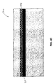
- FIG. 4C is an enlarged partial cross-sectional elevational view of the handle wafer of FIG. 4B following application of a device layer;
- FIG. 5A is an enlarged partial cross-sectional elevational view of a SOI cavity wafer
- FIG. 5B is an enlarged partial cross-sectional elevational view of the SOI cavity wafer of FIG. 5A wherein a surface of the cavity has been roughened;
- FIG. 5C is an enlarged partial cross-sectional elevational view of a SOI cavity wafer with a roughened surface having raised features therein.
- n or p can also mean either n or p or p and n can be substituted therefor.
- n + and p + refer to heavily doped n and p regions, respectively; n ++ and p ++ refer to very heavily doped n and p regions, respectively; n ⁇ and p ⁇ refer to lightly doped n and p regions, respectively; and n ⁇ and p ⁇ refer to very lightly doped n and p regions, respectively.
- such relative doping terms should not be construed as limiting.
- FIG. 1A a partial cross-sectional elevational view of a wafer 10 a manufactured in accordance with various preferred embodiments of the present invention.
- a handle wafer 12 a includes a bottom surface 11 a and a top surface 13 a .
- a dielectric layer 14 a is disposed on the top surface 13 a of the handle wafer 12 a.
- a device layer 16 a is disposed on the dielectric layer 14 a opposite the handle wafer 12 a.
- the device layer 16 a also includes a top surface 17 a and a bottom surface 15 a.
- the bottom surface 15 a of the device layer 16 a is roughened, rather than polished, which reduces the probability of stiction with the handle wafer 12 a once the dielectric layer 14 a is removed.
- FIG. 1B shows a cavity SOI wafer 10 b.
- a cavity 20 b is formed in the handle wafer 12 b from the top surface 13 b extending toward the bottom surface 11 b.
- the dielectric material 14 b does not fill the cavity 20 b, but rather caps the cavity 20 b.
- a bottom surface 15 b of the device layer 16 b is roughened, unlike the smoother top surface 17 b.
- FIG. 1C shows a SOI wafer 10 c wherein the device layer 16 c includes a smooth bottom surface 15 c.
- the top surface 13 c of the handle wafer 12 c, on which the dielectric layer 14 c is disposed, is roughened.
- both the top surface 13 d of the handle wafer 12 d and the bottom surface 15 d of the device layer 16 d are roughened and in contact with the dielectric layer 14 d.
- at least one of the top surface 13 of the handle wafer 12 and the bottom surface 15 of the device layer 16 is roughened to reduce stiction.
- FIGS. 2A-2D illustrate a method of manufacturing a SOI wafer 110 in accordance with one preferred embodiment of the present invention.
- a handle wafer 112 having opposing bottom and top surfaces 111 , 113 is provided.
- the handle wafer 112 is formed of silicon (Si).
- the handle wafer 112 may be formed of other materials such as gallium arsenide (GaAs), germanium (Ge), or the like.
- GaAs gallium arsenide
- Ge germanium
- both the bottom surface 111 and the top surface 113 may be relatively smooth.
- the top surface 113 is roughened according to one or more of various techniques known in the art.
- DRIE deep reactive ion etching
- DRIE utilizes an ionized gas, or plasma, to remove material from the handle wafer 112 , such as, for example, sulfur hexafluoride (SF 6 ).
- An isotropic wet chemical etch is also available for surface roughening.
- Wet etching includes the application of a liquid etchant to the surface 113 of the handle wafer 112 , such as, for example, a hydrofluoric (HF) acid.
- a liquid etchant such as, for example, a hydrofluoric (HF) acid.
- a dielectric or buried oxide layer 114 is formed on the rough top surface 113 of the handle wafer 112 .
- the dielectric layer 114 may be applied using one of thermal growth, low pressure (LP) chemical vapor deposition (CVD), plasma enhanced chemical vapor deposition (PECVD), atmospheric pressure chemical vapor deposition (APCVD), and deposition.
- the dielectric layer 114 is preferably formed of an oxide.
- the dielectric layer 114 may be a nitride, silicon-oxynitride, or other known dielectrics.
- the dielectric layer 114 on the handle wafer 112 may be formed by any known technique.
- the dielectric layer 114 may also be made from multiple layers of the same or different materials.
- a top surface 114 p of the dielectric layer 114 may be ground and/or polished sufficiently to leave a polished, flat, clean surface, which is ideally defect free.
- CMP chemical-mechanical polishing
- CMP employs a polishing pad in conjunction with an applied corrosive chemical slurry.
- CMP is generally a finer process than grinding, though the top surface 114 p of the dielectric layer 114 may first be ground, if necessary, using processes described above to achieve a desired thickness of the dielectric layer 114 .
- a device layer 116 having bottom and top surfaces 115 , 117 can be formed by bonding or otherwise forming a semiconductor layer on the dielectric layer 114 .
- the device layer 116 is silicon.
- the device layer 116 may be formed of other materials such as gallium arsenide, germanium, or the like.
- the device layer 116 is typically a doped p-type or n-type silicon layer.
- the stacked wafers 112 , 116 are annealed (i.e., generally heated to and held at a suitable temperature and then cooled at a suitable rate) to form the bonded-wafer semiconductor device 110 .
- the annealing/bonding process may include heating the stacked wafers 112 , 116 in an annealing furnace for a number of minutes or hours.
- the stacked wafers 112 , 116 may be placed in an annealing furnace at 800-1200° C. for few a minutes to several hours to cause the materials to sufficiently bond.
- the annealing process may be performed in an inert ambient atmosphere, e.g., nitrogen gas, or in an oxidizing ambient atmosphere, e.g., pure oxygen, oxygen/nitrogen mixture, steam or the like.
- an inert ambient atmosphere e.g., nitrogen gas
- an oxidizing ambient atmosphere e.g., pure oxygen, oxygen/nitrogen mixture, steam or the like.
- a “wet” anneal i.e., when steam is the ambient, the steam is generated using a mixture of oxygen and hydrogen typically above 800° C.
- Other known methods of bonding wafers 112 , 116 to form SOI devices 110 include using a liquid oxidant or multiple layers of oxides and/or nitrides between the wafers prior to annealing.
- the top surface 117 of the device layer 116 is ground and polished, according to techniques described above, to the required thickness.
- the SOI device 110 is thus ready for subsequent processing, such as formation of proof masses, removal of a portion of the dielectric layer 114 , or the like.
- the top surface 113 of the handle wafer 112 may be polished while the bottom surface 115 of the device layer 116 may be roughened using one or more of the roughening techniques described above.
- Such a process would result in a SOI wafer 110 similar to the device shown in FIG. 1A . Additional steps may also be performed, such as formation of a cavity in the handle wafer 112 , as shown in FIG. 1B .
- both the top surface 113 of the handle wafer 112 and the bottom surface 115 of the device layer 116 may be roughened using one or more of the techniques described above. Such a process would result in a SOI wafer 110 similar to the device shown in FIG. 1D .
- FIGS. 3A-3C illustrate another method of manufacturing a SOI wafer 210 in accordance with further embodiments of the present invention.
- a handle wafer 212 having opposing bottom and top surfaces 111 , 113 is provided.
- the handle wafer 212 is preferably formed of silicon, but may be formed of other materials such as gallium arsenide, germanium, or the like.
- both the bottom surface 211 and the top surface 213 may be relatively smooth.
- the top surface 213 is then masked with a photoresist patterning layer (not shown) and etched to form a pattern of trenches 230 and mesas 232 , preferably having a very fine pitch, to roughen the top surface 213 .
- the pattern is not limited to the design shown in FIG. 3A but includes any pattern wherein the surface 213 of the handle wafer 212 is sufficiently varied to reduce stiction with the device layer 216 ( FIG. 3C ).
- the trenches 230 may be formed utilizing techniques known in the art such as plasma etching, RIE, sputter etching, vapor phase etching, chemical etching, DRIE, or the like.
- a dielectric or buried oxide layer 214 is formed on the trenched top surface 213 of the handle wafer 212 .
- the buried oxide layer 214 may be applied using one of thermal growth, LPCVD, PECVD, APCVD, and deposition.
- the buried oxide layer 214 is again preferably formed of an oxide but may be a nitride, silicon-oxynitride, or other known dielectrics.
- a device layer 216 having bottom and top surfaces 215 , 217 can be formed by bonding or otherwise forming a semiconductor layer on the buried oxide layer 214 .
- the device layer 216 is preferably silicon, but may be formed of other materials such as gallium arsenide, germanium, or the like.
- the device layer 216 is typically a doped p-type or n-type silicon layer.
- the top surface 217 of the device layer 216 is ground and polished, according to techniques described above, to the required thickness.
- the SOI device 210 is thus ready for subsequent processing, such as formation of proof masses, removal of a portion of the dielectric layer 214 , or the like.
- the top surface 213 of the handle wafer 212 may be polished while the bottom surface 215 of the device layer 216 may include the trench 230 and mesa 232 pattern. Additional steps may also be performed, such as formation of a cavity in the handle wafer 212 .
- both the top surface 213 of the handle wafer 212 and the bottom surface 215 of the device layer 216 may include trench 230 and mesa 232 patterns.
- FIGS. 4A-4C illustrate yet another method of manufacturing a SOI wafer 310 in accordance with still further embodiments of the present invention.
- a dielectric layer 314 is formed on a roughened top surface 313 of a handle wafer 312 as described above.
- An intermediate bonding layer 350 is formed on the top surface 314 p of the dielectric layer 314 , which preferably substantially mirrors the roughening of the handle wafer 312 .
- the intermediate bonding layer 350 is preferably formed of a material suitable for assisting the bonding of the device layer 316 ( FIG. 4C ), such as tetraethyl orthosilicate (TEOS), suitable sol-gels, glass, or the like.
- TEOS tetraethyl orthosilicate
- FIG. 4B a top surface 350 p of the intermediate bonding layer 350 is smoothed using CMP or the like as described above.
- the device layer 316 is formed in FIG. 4C on the top surface 350 p of the intermediate bond
- the top surface 313 of the handle wafer 312 may be polished while the bottom surface 315 of the device layer 316 may be roughened. Additional steps may also be performed, such as formation of a cavity in the handle wafer 312 . Alternatively, both the top surface 313 of the handle wafer 312 and the bottom surface 315 of the device layer 316 may be roughened.
- FIGS. 5A-5C Still another embodiment of the present invention is shown in FIGS. 5A-5C .
- a SOI wafer 410 is shown in FIG. 5A formed from a handle wafer 412 , a dielectric layer 414 , and a device layer 416 .
- a cavity 420 is formed from the top surface 413 of the handle wafer 412 beneath the dielectric layer 414 .
- Surfaces 411 , 413 of the handle wafer 412 and surfaces 415 , 417 of the device layer 416 are shown in FIG. 5A without roughening. However, one or more of the surfaces 411 , 413 , 415 , 417 , or portions thereof, may be roughened according to embodiments of the present invention described above.
- the cavity 420 includes a bottom surface 419 opposite to the dielectric layer 414 .
- the bottom surface 419 of the cavity 420 is roughened to reduce stiction.
- the roughening of the bottom surface 419 is preferably performed using a combination of a chemical oxide growth using highly oxidizing solutions (e.g., ammonia and hydrogen peroxide solution, sulfuric acid and hydrogen peroxide solution, de-ionized water and ozone, or the like) and an RIE silicon etch that, in conjunction with the chemical oxide, provides a heavily micromasked (black silicon) surface.
- highly oxidizing solutions e.g., ammonia and hydrogen peroxide solution, sulfuric acid and hydrogen peroxide solution, de-ionized water and ozone, or the like
- RIE silicon etch that, in conjunction with the chemical oxide, provides a heavily micromasked (black silicon) surface.
- FIG. 5C shows the cavity 420 including several raised features 422 (e.g. pillars, mesas, or the like). Surfaces 421 of the raised features 422 are also preferably roughened as described above.
- the technique described above for roughening the bottom surface of the cavity 420 may also be utilized for other recessed features, such as trenches or the like.
- the recessed features may also be formed from other surfaces (e.g., surfaces 411 , 415 , 417 ) of the handle wafer 412 or device layer 416 .
- the technique described above may be to other surfaces (e.g., surfaces 411 , 413 , 415 , 417 ) or raised features thereon. This technique may thus be used to create antireflection coatings on various devices and sensors.
- recessed features such as the cavity 420
- raised features such as the pillars 422
- the cavity 420 may be formed after roughening of a portion of the top surface 413 of the handle wafer 412 , thus resulting in a roughened bottom surface 419 upon completion of the cavity 420 .
- An advantage is therefore provided in that a recessed feature can be etched to a more precise depth with a greater degree of roughness.
- the surface roughening techniques described above may be applied to any bonded semiconductor substrate involving at least one plane wafer.
- the techniques may be applied to devices having multiple layers of SOI, cavity SOI wafers, and engineered substrates.
- the techniques described above may also be used to form a buried antireflective layer in optical or infrared (IR) applications. Further, roughening of the surfaces may be confined to certain portions, areas, or the like, and need not blanket the entire surface.
Abstract
Description
Claims (10)
Priority Applications (2)
| Application Number | Priority Date | Filing Date | Title |
|---|---|---|---|
| US12/413,972 US8030133B2 (en) | 2008-03-28 | 2009-03-30 | Method of fabricating a bonded wafer substrate for use in MEMS structures |
| US13/179,175 US8253243B2 (en) | 2008-03-28 | 2011-07-08 | Bonded wafer substrate utilizing roughened surfaces for use in MEMS structures |
Applications Claiming Priority (2)
| Application Number | Priority Date | Filing Date | Title |
|---|---|---|---|
| US4021008P | 2008-03-28 | 2008-03-28 | |
| US12/413,972 US8030133B2 (en) | 2008-03-28 | 2009-03-30 | Method of fabricating a bonded wafer substrate for use in MEMS structures |
Related Child Applications (1)
| Application Number | Title | Priority Date | Filing Date |
|---|---|---|---|
| US13/179,175 Division US8253243B2 (en) | 2008-03-28 | 2011-07-08 | Bonded wafer substrate utilizing roughened surfaces for use in MEMS structures |
Publications (2)
| Publication Number | Publication Date |
|---|---|
| US20100065946A1 US20100065946A1 (en) | 2010-03-18 |
| US8030133B2 true US8030133B2 (en) | 2011-10-04 |
Family
ID=42006462
Family Applications (2)
| Application Number | Title | Priority Date | Filing Date |
|---|---|---|---|
| US12/413,972 Active - Reinstated 2030-02-18 US8030133B2 (en) | 2008-03-28 | 2009-03-30 | Method of fabricating a bonded wafer substrate for use in MEMS structures |
| US13/179,175 Active US8253243B2 (en) | 2008-03-28 | 2011-07-08 | Bonded wafer substrate utilizing roughened surfaces for use in MEMS structures |
Family Applications After (1)
| Application Number | Title | Priority Date | Filing Date |
|---|---|---|---|
| US13/179,175 Active US8253243B2 (en) | 2008-03-28 | 2011-07-08 | Bonded wafer substrate utilizing roughened surfaces for use in MEMS structures |
Country Status (1)
| Country | Link |
|---|---|
| US (2) | US8030133B2 (en) |
Cited By (1)
| Publication number | Priority date | Publication date | Assignee | Title |
|---|---|---|---|---|
| US20110260265A1 (en) * | 2008-03-28 | 2011-10-27 | Icemos Technology Ltd. | Bonded wafer substrate for use in mems structures |
Families Citing this family (7)
| Publication number | Priority date | Publication date | Assignee | Title |
|---|---|---|---|---|
| CN102575782B (en) | 2009-08-17 | 2014-04-09 | 盾安美斯泰克股份有限公司 | Micromachined device and control method |
| WO2011094300A2 (en) * | 2010-01-28 | 2011-08-04 | Microstaq, Inc. | Process and structure for high temperature selective fusion bonding |
| US8232614B1 (en) * | 2011-03-08 | 2012-07-31 | Taiwan Semiconductor Manufacturing Company, Ltd. | Package systems having a conductive element through a substrate thereof and manufacturing methods of the same |
| FR2973569A1 (en) * | 2011-04-01 | 2012-10-05 | St Microelectronics Sa | Integrated circuit manufacturing method, involves removing part of plate to leave silicon residual layer on insulating layer, and forming high frequency component in and/or above residual layer, or directly above some of cavities |
| US10273141B2 (en) * | 2016-04-26 | 2019-04-30 | Taiwan Semiconductor Manufacturing Co., Ltd. | Rough layer for better anti-stiction deposition |
| EP3543795A1 (en) * | 2018-03-20 | 2019-09-25 | Patek Philippe SA Genève | Method for manufacturing silicon clock components |
| US11305988B2 (en) * | 2020-09-01 | 2022-04-19 | Aac Acoustic Technologies (Shenzhen) Co., Ltd. | Method for preparing silicon wafer with rough surface and silicon wafer |
Citations (82)
| Publication number | Priority date | Publication date | Assignee | Title |
|---|---|---|---|---|
| US4158206A (en) | 1977-02-07 | 1979-06-12 | Rca Corporation | Semiconductor device |
| US4211582A (en) | 1979-06-28 | 1980-07-08 | International Business Machines Corporation | Process for making large area isolation trenches utilizing a two-step selective etching technique |
| US4238278A (en) | 1979-06-14 | 1980-12-09 | International Business Machines Corporation | Polycrystalline silicon oxidation method for making shallow and deep isolation trenches |
| US4491486A (en) | 1981-09-17 | 1985-01-01 | Tokyo Shibaura Denki Kabushiki Kaisha | Method for manufacturing a semiconductor device |
| US4771016A (en) | 1987-04-24 | 1988-09-13 | Harris Corporation | Using a rapid thermal process for manufacturing a wafer bonded soi semiconductor |
| US4866004A (en) | 1985-10-05 | 1989-09-12 | Fujitsu Limited | Method of forming groove isolation filled with dielectric for semiconductor device |
| US4895810A (en) | 1986-03-21 | 1990-01-23 | Advanced Power Technology, Inc. | Iopographic pattern delineated power mosfet with profile tailored recessed source |
| US4994406A (en) | 1989-11-03 | 1991-02-19 | Motorola Inc. | Method of fabricating semiconductor devices having deep and shallow isolation structures |
| US5019522A (en) | 1986-03-21 | 1991-05-28 | Advanced Power Technology, Inc. | Method of making topographic pattern delineated power MOSFET with profile tailored recessed source |
| US5045903A (en) | 1988-05-17 | 1991-09-03 | Advanced Power Technology, Inc. | Topographic pattern delineated power MOSFET with profile tailored recessed source |
| US5216275A (en) | 1991-03-19 | 1993-06-01 | University Of Electronic Science And Technology Of China | Semiconductor power devices with alternating conductivity type high-voltage breakdown regions |
| US5266135A (en) | 1990-02-07 | 1993-11-30 | Harris Corporation | Wafer bonding process employing liquid oxidant |
| US5362667A (en) | 1992-07-28 | 1994-11-08 | Harris Corporation | Bonded wafer processing |
| US5366914A (en) | 1992-01-29 | 1994-11-22 | Nec Corporation | Vertical power MOSFET structure having reduced cell area |
| US5387555A (en) | 1992-09-03 | 1995-02-07 | Harris Corporation | Bonded wafer processing with metal silicidation |
| US5395790A (en) | 1994-05-11 | 1995-03-07 | United Microelectronics Corp. | Stress-free isolation layer |
| US5432113A (en) | 1992-08-04 | 1995-07-11 | Nippon Steel Corporation | Method of making a semiconductor memory device |
| US5435888A (en) | 1993-12-06 | 1995-07-25 | Sgs-Thomson Microelectronics, Inc. | Enhanced planarization technique for an integrated circuit |
| US5472888A (en) | 1988-02-25 | 1995-12-05 | International Rectifier Corporation | Depletion mode power MOSFET with refractory gate and method of making same |
| US5506421A (en) | 1992-11-24 | 1996-04-09 | Cree Research, Inc. | Power MOSFET in silicon carbide |
| US5598018A (en) | 1978-10-13 | 1997-01-28 | International Rectifier Corporation | High power MOSFET with low on-resistance and high breakdown voltage |
| US5726469A (en) | 1994-07-20 | 1998-03-10 | University Of Elec. Sci. & Tech. Of China | Surface voltage sustaining structure for semiconductor devices |
| US5744852A (en) | 1995-05-17 | 1998-04-28 | Harris Corporation | Bonded wafer |
| US5744994A (en) | 1996-05-15 | 1998-04-28 | Siliconix Incorporated | Three-terminal power mosfet switch for use as synchronous rectifier or voltage clamp |
| US5849627A (en) | 1990-02-07 | 1998-12-15 | Harris Corporation | Bonded wafer processing with oxidative bonding |
| US5902127A (en) | 1996-06-17 | 1999-05-11 | Samsung Electronics Co., Ltd. | Methods for forming isolation trenches including doped silicon oxide |
| US5926713A (en) | 1996-04-17 | 1999-07-20 | Advanced Micro Devices, Inc. | Method for achieving global planarization by forming minimum mesas in large field areas |
| US5939754A (en) | 1996-09-09 | 1999-08-17 | Nissan Motor Co., Ltd. | Power MOSFET having a drain heterojunction |
| US5994751A (en) | 1995-08-03 | 1999-11-30 | Siemens Aktiengesellschaft | Photodiode having reduced series resistance, and method for fabrication thereof |
| US6008106A (en) | 1997-07-15 | 1999-12-28 | Mosel Vitelic Inc. | Micro-trench oxidation by using rough oxide mask for field isolation |
| US6081009A (en) | 1997-11-10 | 2000-06-27 | Intersil Corporation | High voltage mosfet structure |
| US6174773B1 (en) | 1995-02-17 | 2001-01-16 | Fuji Electric Co., Ltd. | Method of manufacturing vertical trench misfet |
| US6175141B1 (en) | 1995-12-21 | 2001-01-16 | Dr. Johanne Heidenhain Gmbh | Opto-electronic sensor component |
| US6184555B1 (en) | 1996-02-05 | 2001-02-06 | Siemens Aktiengesellschaft | Field effect-controlled semiconductor component |
| US6190970B1 (en) | 1999-01-04 | 2001-02-20 | Industrial Technology Research Institute | Method of making power MOSFET and IGBT with optimized on-resistance and breakdown voltage |
| US6198127B1 (en) | 1999-05-19 | 2001-03-06 | Intersil Corporation | MOS-gated power device having extended trench and doping zone and process for forming same |
| US6214698B1 (en) | 2000-01-11 | 2001-04-10 | Taiwan Semiconductor Manufacturing Company | Shallow trench isolation methods employing gap filling doped silicon oxide dielectric layer |
| US6222229B1 (en) | 1999-02-18 | 2001-04-24 | Cree, Inc. | Self-aligned shield structure for realizing high frequency power MOSFET devices with improved reliability |
| US6239463B1 (en) | 1997-08-28 | 2001-05-29 | Siliconix Incorporated | Low resistance power MOSFET or other device containing silicon-germanium layer |
| US6265281B1 (en) | 1997-08-18 | 2001-07-24 | Micron Technology, Inc. | Method for forming dielectric within a recess |
| US6291856B1 (en) | 1998-11-12 | 2001-09-18 | Fuji Electric Co., Ltd. | Semiconductor device with alternating conductivity type layer and method of manufacturing the same |
| US6300171B1 (en) | 1998-12-09 | 2001-10-09 | Stmicroelectronics S.R.L. | Method of manufacturing an integrated edge structure for high voltage semiconductor devices, and related integrated edge structure |
| US6307246B1 (en) | 1998-07-23 | 2001-10-23 | Mitsubishi Denki Kabushiki Kaisha | Semiconductor resurf devices formed by oblique trench implantation |
| US6310365B1 (en) | 1998-07-23 | 2001-10-30 | University Of Electronic Science And Technology | Surface voltage sustaining structure for semiconductor devices having floating voltage terminal |
| US6362505B1 (en) | 1998-11-27 | 2002-03-26 | Siemens Aktiengesellschaft | MOS field-effect transistor with auxiliary electrode |
| US6391723B1 (en) | 1999-05-31 | 2002-05-21 | Stmicroelectronics S.R.L. | Fabrication of VDMOS structure with reduced parasitic effects |
| US20020070418A1 (en) | 2000-12-07 | 2002-06-13 | International Rectifier Corporation | High voltage vertical conduction superjunction semiconductor device |
| US6410958B1 (en) | 2000-11-27 | 2002-06-25 | Kabushiki Kaisha Toshiba | Power MOSFET having laterally three-layered structure formed among element isolation regions |
| US6426991B1 (en) | 2000-11-16 | 2002-07-30 | Koninklijke Philips Electronics N.V. | Back-illuminated photodiodes for computed tomography detectors |
| US6452230B1 (en) | 1998-12-23 | 2002-09-17 | International Rectifier Corporation | High voltage mosgated device with trenches to reduce on-resistance |
| US6459124B1 (en) | 1996-10-02 | 2002-10-01 | Semiconductor Energy Laboratory Co., Ltd. | Semiconductor device and process for manufacturing the same, and electronic device |
| US6465325B2 (en) | 2001-02-27 | 2002-10-15 | Fairchild Semiconductor Corporation | Process for depositing and planarizing BPSG for dense trench MOSFET application |
| US6495421B2 (en) | 1999-12-15 | 2002-12-17 | Koninklijke Philips Electronics N.V. | Manufacture of semiconductor material and devices using that material |
| US6501146B1 (en) | 1997-06-18 | 2002-12-31 | Mitsubishi Denki Kabushiki Kaisha | Semiconductor device and method of manufacturing thereof |
| US6501130B2 (en) | 2001-01-24 | 2002-12-31 | Power Integrations, Inc. | High-voltage transistor with buried conduction layer |
| US6504230B2 (en) | 1999-09-07 | 2003-01-07 | Infineon Technologies Ag | Compensation component and method for fabricating the compensation component |
| US6509220B2 (en) | 2000-11-27 | 2003-01-21 | Power Integrations, Inc. | Method of fabricating a high-voltage transistor |
| US6512267B2 (en) | 2001-04-12 | 2003-01-28 | International Rectifier Corporation | Superjunction device with self compensated trench walls |
| US6534367B2 (en) | 2001-04-28 | 2003-03-18 | Koninklijke Philips Electronics N.V. | Trench-gate semiconductor devices and their manufacture |
| US6566201B1 (en) | 2001-12-31 | 2003-05-20 | General Semiconductor, Inc. | Method for fabricating a high voltage power MOSFET having a voltage sustaining region that includes doped columns formed by rapid diffusion |
| US6613644B2 (en) | 2000-08-22 | 2003-09-02 | Infineon Technologies Ag | Method for forming a dielectric zone in a semiconductor substrate |
| US6624494B2 (en) | 2001-10-04 | 2003-09-23 | General Semiconductor, Inc. | Method for fabricating a power semiconductor device having a floating island voltage sustaining layer |
| US6635906B1 (en) | 1993-10-29 | 2003-10-21 | Third Dimension (3D) Semiconductor | Voltage sustaining layer with opposite-doped islands for semi-conductor power devices |
| US6686244B2 (en) | 2002-03-21 | 2004-02-03 | General Semiconductor, Inc. | Power semiconductor device having a voltage sustaining region that includes doped columns formed with a single ion implantation step |
| US6710418B1 (en) | 2002-10-11 | 2004-03-23 | Fairchild Semiconductor Corporation | Schottky rectifier with insulation-filled trenches and method of forming the same |
| US6710403B2 (en) | 2002-07-30 | 2004-03-23 | Fairchild Semiconductor Corporation | Dual trench power MOSFET |
| US6713813B2 (en) | 2001-01-30 | 2004-03-30 | Fairchild Semiconductor Corporation | Field effect transistor having a lateral depletion structure |
| US6762473B1 (en) | 2003-06-25 | 2004-07-13 | Semicoa Semiconductors | Ultra thin back-illuminated photodiode array structures and fabrication methods |
| US6787872B2 (en) | 2001-06-26 | 2004-09-07 | International Rectifier Corporation | Lateral conduction superjunction semiconductor device |
| US6797589B2 (en) | 2001-12-18 | 2004-09-28 | Kionix, Inc. | Insulating micro-structure and method of manufacturing same |
| WO2005031880A1 (en) | 2003-09-26 | 2005-04-07 | Semicoa Semiconductors | Fast silicon photodiodes with high back surface reflectance in a wavelength range close to the bandgap |
| US20050090107A1 (en) * | 2003-10-21 | 2005-04-28 | Draney Nathan R. | Substrate with enhanced properties for planarization |
| US20050176192A1 (en) | 2003-12-19 | 2005-08-11 | Third Dimension (3D) Semiconductor, Inc. | Planarization method of manufacturing a superjunction device |
| US6936907B2 (en) | 2002-08-29 | 2005-08-30 | The University Of Electronic Science And Technology Of China | Lateral high-voltage semiconductor devices with surface covered by thin film of dielectric material with high permittivity |
| US6998681B2 (en) | 2003-10-16 | 2006-02-14 | University Of Electronic Science And Technology | Lateral low-side and high-side high-voltage devices |
| US7015104B1 (en) | 2003-05-29 | 2006-03-21 | Third Dimension Semiconductor, Inc. | Technique for forming the deep doped columns in superjunction |
| US7023069B2 (en) | 2003-12-19 | 2006-04-04 | Third Dimension (3D) Semiconductor, Inc. | Method for forming thick dielectric regions using etched trenches |
| US7041560B2 (en) | 2003-12-19 | 2006-05-09 | Third Dimension (3D) Semiconductor, Inc. | Method of manufacturing a superjunction device with conventional terminations |
| US7052982B2 (en) | 2003-12-19 | 2006-05-30 | Third Dimension (3D) Semiconductor, Inc. | Method for manufacturing a superjunction device with wide mesas |
| US7109110B2 (en) | 2003-12-19 | 2006-09-19 | Third Dimension (3D) Semiconductor, Inc. | Method of manufacturing a superjunction device |
| US20070063217A1 (en) * | 2005-08-22 | 2007-03-22 | Icemos Technology Corporation | Bonded-wafer Superjunction Semiconductor Device |
| US7242069B2 (en) | 2003-05-05 | 2007-07-10 | Udt Sensors, Inc. | Thin wafer detectors with improved radiation damage and crosstalk characteristics |
Family Cites Families (2)
| Publication number | Priority date | Publication date | Assignee | Title |
|---|---|---|---|---|
| US5994207A (en) * | 1997-05-12 | 1999-11-30 | Silicon Genesis Corporation | Controlled cleavage process using pressurized fluid |
| US8030133B2 (en) * | 2008-03-28 | 2011-10-04 | Icemos Technology Ltd. | Method of fabricating a bonded wafer substrate for use in MEMS structures |
-
2009
- 2009-03-30 US US12/413,972 patent/US8030133B2/en active Active - Reinstated
-
2011
- 2011-07-08 US US13/179,175 patent/US8253243B2/en active Active
Patent Citations (94)
| Publication number | Priority date | Publication date | Assignee | Title |
|---|---|---|---|---|
| US4158206A (en) | 1977-02-07 | 1979-06-12 | Rca Corporation | Semiconductor device |
| US5598018A (en) | 1978-10-13 | 1997-01-28 | International Rectifier Corporation | High power MOSFET with low on-resistance and high breakdown voltage |
| US5742087A (en) | 1978-10-13 | 1998-04-21 | International Rectifier Corporation | High power MOSFET with low on-resistance and high breakdown voltage |
| US4238278A (en) | 1979-06-14 | 1980-12-09 | International Business Machines Corporation | Polycrystalline silicon oxidation method for making shallow and deep isolation trenches |
| US4211582A (en) | 1979-06-28 | 1980-07-08 | International Business Machines Corporation | Process for making large area isolation trenches utilizing a two-step selective etching technique |
| US4491486A (en) | 1981-09-17 | 1985-01-01 | Tokyo Shibaura Denki Kabushiki Kaisha | Method for manufacturing a semiconductor device |
| US4866004A (en) | 1985-10-05 | 1989-09-12 | Fujitsu Limited | Method of forming groove isolation filled with dielectric for semiconductor device |
| US4895810A (en) | 1986-03-21 | 1990-01-23 | Advanced Power Technology, Inc. | Iopographic pattern delineated power mosfet with profile tailored recessed source |
| US5019522A (en) | 1986-03-21 | 1991-05-28 | Advanced Power Technology, Inc. | Method of making topographic pattern delineated power MOSFET with profile tailored recessed source |
| US4771016A (en) | 1987-04-24 | 1988-09-13 | Harris Corporation | Using a rapid thermal process for manufacturing a wafer bonded soi semiconductor |
| US5786619A (en) | 1988-02-25 | 1998-07-28 | International Rectifier Corporation | Depletion mode power MOSFET with refractory gate and method of making same |
| US5472888A (en) | 1988-02-25 | 1995-12-05 | International Rectifier Corporation | Depletion mode power MOSFET with refractory gate and method of making same |
| US5045903A (en) | 1988-05-17 | 1991-09-03 | Advanced Power Technology, Inc. | Topographic pattern delineated power MOSFET with profile tailored recessed source |
| US4994406A (en) | 1989-11-03 | 1991-02-19 | Motorola Inc. | Method of fabricating semiconductor devices having deep and shallow isolation structures |
| US5266135A (en) | 1990-02-07 | 1993-11-30 | Harris Corporation | Wafer bonding process employing liquid oxidant |
| US5334273A (en) | 1990-02-07 | 1994-08-02 | Harris Corporation | Wafer bonding using trapped oxidizing vapor |
| US5849627A (en) | 1990-02-07 | 1998-12-15 | Harris Corporation | Bonded wafer processing with oxidative bonding |
| US5216275A (en) | 1991-03-19 | 1993-06-01 | University Of Electronic Science And Technology Of China | Semiconductor power devices with alternating conductivity type high-voltage breakdown regions |
| US5366914A (en) | 1992-01-29 | 1994-11-22 | Nec Corporation | Vertical power MOSFET structure having reduced cell area |
| US5728624A (en) | 1992-07-28 | 1998-03-17 | Harris Corporation | Bonded wafer processing |
| US5517047A (en) | 1992-07-28 | 1996-05-14 | Harris Corporation | Bonded wafer processing |
| US5362667A (en) | 1992-07-28 | 1994-11-08 | Harris Corporation | Bonded wafer processing |
| US5432113A (en) | 1992-08-04 | 1995-07-11 | Nippon Steel Corporation | Method of making a semiconductor memory device |
| US5387555A (en) | 1992-09-03 | 1995-02-07 | Harris Corporation | Bonded wafer processing with metal silicidation |
| US5506421A (en) | 1992-11-24 | 1996-04-09 | Cree Research, Inc. | Power MOSFET in silicon carbide |
| US6635906B1 (en) | 1993-10-29 | 2003-10-21 | Third Dimension (3D) Semiconductor | Voltage sustaining layer with opposite-doped islands for semi-conductor power devices |
| US6936867B2 (en) | 1993-10-29 | 2005-08-30 | Third Dimension Semiconductor, Inc. | Semiconductor high-voltage devices |
| US5435888A (en) | 1993-12-06 | 1995-07-25 | Sgs-Thomson Microelectronics, Inc. | Enhanced planarization technique for an integrated circuit |
| US5395790A (en) | 1994-05-11 | 1995-03-07 | United Microelectronics Corp. | Stress-free isolation layer |
| US5726469A (en) | 1994-07-20 | 1998-03-10 | University Of Elec. Sci. & Tech. Of China | Surface voltage sustaining structure for semiconductor devices |
| US6174773B1 (en) | 1995-02-17 | 2001-01-16 | Fuji Electric Co., Ltd. | Method of manufacturing vertical trench misfet |
| US5744852A (en) | 1995-05-17 | 1998-04-28 | Harris Corporation | Bonded wafer |
| US5994751A (en) | 1995-08-03 | 1999-11-30 | Siemens Aktiengesellschaft | Photodiode having reduced series resistance, and method for fabrication thereof |
| US6175141B1 (en) | 1995-12-21 | 2001-01-16 | Dr. Johanne Heidenhain Gmbh | Opto-electronic sensor component |
| US6184555B1 (en) | 1996-02-05 | 2001-02-06 | Siemens Aktiengesellschaft | Field effect-controlled semiconductor component |
| US5926713A (en) | 1996-04-17 | 1999-07-20 | Advanced Micro Devices, Inc. | Method for achieving global planarization by forming minimum mesas in large field areas |
| US5744994A (en) | 1996-05-15 | 1998-04-28 | Siliconix Incorporated | Three-terminal power mosfet switch for use as synchronous rectifier or voltage clamp |
| US5929690A (en) | 1996-05-15 | 1999-07-27 | Siliconix Incorporated | Three-terminal power MOSFET switch for use as synchronous rectifier or voltage clamp |
| US5902127A (en) | 1996-06-17 | 1999-05-11 | Samsung Electronics Co., Ltd. | Methods for forming isolation trenches including doped silicon oxide |
| US5939754A (en) | 1996-09-09 | 1999-08-17 | Nissan Motor Co., Ltd. | Power MOSFET having a drain heterojunction |
| US6459124B1 (en) | 1996-10-02 | 2002-10-01 | Semiconductor Energy Laboratory Co., Ltd. | Semiconductor device and process for manufacturing the same, and electronic device |
| US6501146B1 (en) | 1997-06-18 | 2002-12-31 | Mitsubishi Denki Kabushiki Kaisha | Semiconductor device and method of manufacturing thereof |
| US6008106A (en) | 1997-07-15 | 1999-12-28 | Mosel Vitelic Inc. | Micro-trench oxidation by using rough oxide mask for field isolation |
| US6265281B1 (en) | 1997-08-18 | 2001-07-24 | Micron Technology, Inc. | Method for forming dielectric within a recess |
| US6239463B1 (en) | 1997-08-28 | 2001-05-29 | Siliconix Incorporated | Low resistance power MOSFET or other device containing silicon-germanium layer |
| US6081009A (en) | 1997-11-10 | 2000-06-27 | Intersil Corporation | High voltage mosfet structure |
| US6307246B1 (en) | 1998-07-23 | 2001-10-23 | Mitsubishi Denki Kabushiki Kaisha | Semiconductor resurf devices formed by oblique trench implantation |
| US6310365B1 (en) | 1998-07-23 | 2001-10-30 | University Of Electronic Science And Technology | Surface voltage sustaining structure for semiconductor devices having floating voltage terminal |
| US6291856B1 (en) | 1998-11-12 | 2001-09-18 | Fuji Electric Co., Ltd. | Semiconductor device with alternating conductivity type layer and method of manufacturing the same |
| US6362505B1 (en) | 1998-11-27 | 2002-03-26 | Siemens Aktiengesellschaft | MOS field-effect transistor with auxiliary electrode |
| US6300171B1 (en) | 1998-12-09 | 2001-10-09 | Stmicroelectronics S.R.L. | Method of manufacturing an integrated edge structure for high voltage semiconductor devices, and related integrated edge structure |
| US6452230B1 (en) | 1998-12-23 | 2002-09-17 | International Rectifier Corporation | High voltage mosgated device with trenches to reduce on-resistance |
| US6359309B1 (en) | 1999-01-04 | 2002-03-19 | Industrial Technology Research Institute | Power MOSFET and IGBT with optimized on-resistance and breakdown voltage |
| US6190970B1 (en) | 1999-01-04 | 2001-02-20 | Industrial Technology Research Institute | Method of making power MOSFET and IGBT with optimized on-resistance and breakdown voltage |
| US6222229B1 (en) | 1999-02-18 | 2001-04-24 | Cree, Inc. | Self-aligned shield structure for realizing high frequency power MOSFET devices with improved reliability |
| US6198127B1 (en) | 1999-05-19 | 2001-03-06 | Intersil Corporation | MOS-gated power device having extended trench and doping zone and process for forming same |
| US6391723B1 (en) | 1999-05-31 | 2002-05-21 | Stmicroelectronics S.R.L. | Fabrication of VDMOS structure with reduced parasitic effects |
| US6504230B2 (en) | 1999-09-07 | 2003-01-07 | Infineon Technologies Ag | Compensation component and method for fabricating the compensation component |
| US6495421B2 (en) | 1999-12-15 | 2002-12-17 | Koninklijke Philips Electronics N.V. | Manufacture of semiconductor material and devices using that material |
| US6214698B1 (en) | 2000-01-11 | 2001-04-10 | Taiwan Semiconductor Manufacturing Company | Shallow trench isolation methods employing gap filling doped silicon oxide dielectric layer |
| US6613644B2 (en) | 2000-08-22 | 2003-09-02 | Infineon Technologies Ag | Method for forming a dielectric zone in a semiconductor substrate |
| US6426991B1 (en) | 2000-11-16 | 2002-07-30 | Koninklijke Philips Electronics N.V. | Back-illuminated photodiodes for computed tomography detectors |
| US6509220B2 (en) | 2000-11-27 | 2003-01-21 | Power Integrations, Inc. | Method of fabricating a high-voltage transistor |
| US6410958B1 (en) | 2000-11-27 | 2002-06-25 | Kabushiki Kaisha Toshiba | Power MOSFET having laterally three-layered structure formed among element isolation regions |
| US20020070418A1 (en) | 2000-12-07 | 2002-06-13 | International Rectifier Corporation | High voltage vertical conduction superjunction semiconductor device |
| US6501130B2 (en) | 2001-01-24 | 2002-12-31 | Power Integrations, Inc. | High-voltage transistor with buried conduction layer |
| US6713813B2 (en) | 2001-01-30 | 2004-03-30 | Fairchild Semiconductor Corporation | Field effect transistor having a lateral depletion structure |
| US6465325B2 (en) | 2001-02-27 | 2002-10-15 | Fairchild Semiconductor Corporation | Process for depositing and planarizing BPSG for dense trench MOSFET application |
| US6512267B2 (en) | 2001-04-12 | 2003-01-28 | International Rectifier Corporation | Superjunction device with self compensated trench walls |
| US6534367B2 (en) | 2001-04-28 | 2003-03-18 | Koninklijke Philips Electronics N.V. | Trench-gate semiconductor devices and their manufacture |
| US6787872B2 (en) | 2001-06-26 | 2004-09-07 | International Rectifier Corporation | Lateral conduction superjunction semiconductor device |
| US6624494B2 (en) | 2001-10-04 | 2003-09-23 | General Semiconductor, Inc. | Method for fabricating a power semiconductor device having a floating island voltage sustaining layer |
| US6797589B2 (en) | 2001-12-18 | 2004-09-28 | Kionix, Inc. | Insulating micro-structure and method of manufacturing same |
| US6566201B1 (en) | 2001-12-31 | 2003-05-20 | General Semiconductor, Inc. | Method for fabricating a high voltage power MOSFET having a voltage sustaining region that includes doped columns formed by rapid diffusion |
| US6710400B2 (en) | 2001-12-31 | 2004-03-23 | General Semiconductor, Inc. | Method for fabricating a high voltage power MOSFET having a voltage sustaining region that includes doped columns formed by rapid diffusion |
| US6686244B2 (en) | 2002-03-21 | 2004-02-03 | General Semiconductor, Inc. | Power semiconductor device having a voltage sustaining region that includes doped columns formed with a single ion implantation step |
| US6710403B2 (en) | 2002-07-30 | 2004-03-23 | Fairchild Semiconductor Corporation | Dual trench power MOSFET |
| US6936907B2 (en) | 2002-08-29 | 2005-08-30 | The University Of Electronic Science And Technology Of China | Lateral high-voltage semiconductor devices with surface covered by thin film of dielectric material with high permittivity |
| US6710418B1 (en) | 2002-10-11 | 2004-03-23 | Fairchild Semiconductor Corporation | Schottky rectifier with insulation-filled trenches and method of forming the same |
| US7242069B2 (en) | 2003-05-05 | 2007-07-10 | Udt Sensors, Inc. | Thin wafer detectors with improved radiation damage and crosstalk characteristics |
| US7015104B1 (en) | 2003-05-29 | 2006-03-21 | Third Dimension Semiconductor, Inc. | Technique for forming the deep doped columns in superjunction |
| US6762473B1 (en) | 2003-06-25 | 2004-07-13 | Semicoa Semiconductors | Ultra thin back-illuminated photodiode array structures and fabrication methods |
| WO2005001941A2 (en) | 2003-06-25 | 2005-01-06 | Semicoa | Ultra thin back-illuminated photodiode array structures and fabrication methods |
| WO2005031880A1 (en) | 2003-09-26 | 2005-04-07 | Semicoa Semiconductors | Fast silicon photodiodes with high back surface reflectance in a wavelength range close to the bandgap |
| US6998681B2 (en) | 2003-10-16 | 2006-02-14 | University Of Electronic Science And Technology | Lateral low-side and high-side high-voltage devices |
| US20050090107A1 (en) * | 2003-10-21 | 2005-04-28 | Draney Nathan R. | Substrate with enhanced properties for planarization |
| US20050176192A1 (en) | 2003-12-19 | 2005-08-11 | Third Dimension (3D) Semiconductor, Inc. | Planarization method of manufacturing a superjunction device |
| US7023069B2 (en) | 2003-12-19 | 2006-04-04 | Third Dimension (3D) Semiconductor, Inc. | Method for forming thick dielectric regions using etched trenches |
| US7041560B2 (en) | 2003-12-19 | 2006-05-09 | Third Dimension (3D) Semiconductor, Inc. | Method of manufacturing a superjunction device with conventional terminations |
| US7052982B2 (en) | 2003-12-19 | 2006-05-30 | Third Dimension (3D) Semiconductor, Inc. | Method for manufacturing a superjunction device with wide mesas |
| US7109110B2 (en) | 2003-12-19 | 2006-09-19 | Third Dimension (3D) Semiconductor, Inc. | Method of manufacturing a superjunction device |
| US20070063217A1 (en) * | 2005-08-22 | 2007-03-22 | Icemos Technology Corporation | Bonded-wafer Superjunction Semiconductor Device |
| US7446018B2 (en) | 2005-08-22 | 2008-11-04 | Icemos Technology Corporation | Bonded-wafer superjunction semiconductor device |
| US7579667B2 (en) | 2005-08-22 | 2009-08-25 | Icemos Technology Ltd. | Bonded-wafer superjunction semiconductor device |
Cited By (2)
| Publication number | Priority date | Publication date | Assignee | Title |
|---|---|---|---|---|
| US20110260265A1 (en) * | 2008-03-28 | 2011-10-27 | Icemos Technology Ltd. | Bonded wafer substrate for use in mems structures |
| US8253243B2 (en) * | 2008-03-28 | 2012-08-28 | Icemos Technology Ltd. | Bonded wafer substrate utilizing roughened surfaces for use in MEMS structures |
Also Published As
| Publication number | Publication date |
|---|---|
| US20110260265A1 (en) | 2011-10-27 |
| US20100065946A1 (en) | 2010-03-18 |
| US8253243B2 (en) | 2012-08-28 |
Similar Documents
| Publication | Publication Date | Title |
|---|---|---|
| US8253243B2 (en) | Bonded wafer substrate utilizing roughened surfaces for use in MEMS structures | |
| US9458009B2 (en) | Semiconductor devices and methods of forming thereof | |
| US6096433A (en) | Laminated substrate fabricated from semiconductor wafers bonded to each other without contact between insulating layer and semiconductor layer and process of fabrication thereof | |
| US8481365B2 (en) | MEMS devices | |
| CN102341900B (en) | Method of producing a heterostructure with local adaptation of the thermal expansion coefficient | |
| CN101996922B (en) | Silicon on insulator (SOI) wafer and formation method thereof | |
| WO2007015951A3 (en) | Semiconductor structures formed on substrates and methods of manufacturing the same | |
| US9731960B2 (en) | MEMS capping method | |
| WO2009133506A2 (en) | Mems device and manufacturing method | |
| US5449638A (en) | Process on thickness control for silicon-on-insulator technology | |
| US20050112843A1 (en) | Method for anodic bonding of wafers and device | |
| WO2015074479A1 (en) | Low-warpage semiconductor substrate and method of preparing same | |
| US11610808B2 (en) | Semiconductor wafer with low defect count and method for manufacturing thereof | |
| WO2008090426A1 (en) | Process for forming and controlling rough interfaces | |
| JP2007173694A (en) | Method of manufacturing semiconductor substrate | |
| US20170076976A1 (en) | Isolation structure and method for fabricating the same | |
| US9576842B2 (en) | Grass removal in patterned cavity etching | |
| EP1482539A1 (en) | Preparation method for protecting the back side of a wafer and back side protected wafer | |
| WO2004013038A3 (en) | Etch stop control for mems device formation | |
| JPH11126910A (en) | Manufacture of semiconductor substrate for pressure sensor | |
| US20130189821A1 (en) | Methods for fabricating semiconductor devices with reduced damage to shallow trench isolation (sti) regions | |
| CN116936460A (en) | Glass substrate structure on silicon-based insulator and manufacturing method thereof | |
| CN117855037A (en) | Semiconductor structure and preparation method thereof | |
| KR20220001720A (en) | Producing method of silicon on insulator substrate | |
| CN117897036A (en) | Semiconductor device and manufacturing method thereof |
Legal Events
| Date | Code | Title | Description |
|---|---|---|---|
| STCF | Information on status: patent grant |
Free format text: PATENTED CASE |
|
| REMI | Maintenance fee reminder mailed | ||
| FPAY | Fee payment |
Year of fee payment: 4 |
|
| SULP | Surcharge for late payment | ||
| FEPP | Fee payment procedure |
Free format text: MAINTENANCE FEE REMINDER MAILED (ORIGINAL EVENT CODE: REM.); ENTITY STATUS OF PATENT OWNER: LARGE ENTITY |
|
| LAPS | Lapse for failure to pay maintenance fees |
Free format text: PATENT EXPIRED FOR FAILURE TO PAY MAINTENANCE FEES (ORIGINAL EVENT CODE: EXP.); ENTITY STATUS OF PATENT OWNER: LARGE ENTITY |
|
| PRDP | Patent reinstated due to the acceptance of a late maintenance fee |
Effective date: 20191112 |
|
| FEPP | Fee payment procedure |
Free format text: SURCHARGE, PETITION TO ACCEPT PYMT AFTER EXP, UNINTENTIONAL (ORIGINAL EVENT CODE: M1558); ENTITY STATUS OF PATENT OWNER: LARGE ENTITY Free format text: PETITION RELATED TO MAINTENANCE FEES GRANTED (ORIGINAL EVENT CODE: PMFG); ENTITY STATUS OF PATENT OWNER: LARGE ENTITY Free format text: PETITION RELATED TO MAINTENANCE FEES FILED (ORIGINAL EVENT CODE: PMFP); ENTITY STATUS OF PATENT OWNER: LARGE ENTITY |
|
| MAFP | Maintenance fee payment |
Free format text: PAYMENT OF MAINTENANCE FEE, 8TH YEAR, LARGE ENTITY (ORIGINAL EVENT CODE: M1552); ENTITY STATUS OF PATENT OWNER: LARGE ENTITY Year of fee payment: 8 |
|
| STCF | Information on status: patent grant |
Free format text: PATENTED CASE |
|
| FP | Lapsed due to failure to pay maintenance fee |
Effective date: 20191004 |
|
| MAFP | Maintenance fee payment |
Free format text: PAYMENT OF MAINTENANCE FEE, 12TH YEAR, LARGE ENTITY (ORIGINAL EVENT CODE: M1553); ENTITY STATUS OF PATENT OWNER: LARGE ENTITY Year of fee payment: 12 |