US8037579B2 - Cable tie sleeve - Google Patents

Cable tie sleeve Download PDF

Info

Publication number
US8037579B2
US8037579B2 US11/861,404 US86140407A US8037579B2 US 8037579 B2 US8037579 B2 US 8037579B2 US 86140407 A US86140407 A US 86140407A US 8037579 B2 US8037579 B2 US 8037579B2
Authority
US
United States
Prior art keywords
sleeve
sidewalls
strap
cable tie
spaced
Prior art date
Legal status (The legal status is an assumption and is not a legal conclusion. Google has not performed a legal analysis and makes no representation as to the accuracy of the status listed.)
Expired - Fee Related, expires
Application number
US11/861,404
Other versions
US20090077772A1 (en
Inventor
Kenneth Tomasetti
Current Assignee (The listed assignees may be inaccurate. Google has not performed a legal analysis and makes no representation or warranty as to the accuracy of the list.)
Advanced Cable Ties Inc
Original Assignee
Advanced Cable Ties Inc
Priority date (The priority date is an assumption and is not a legal conclusion. Google has not performed a legal analysis and makes no representation as to the accuracy of the date listed.)
Filing date
Publication date
Application filed by Advanced Cable Ties Inc filed Critical Advanced Cable Ties Inc
Priority to US11/861,404 priority Critical patent/US8037579B2/en
Publication of US20090077772A1 publication Critical patent/US20090077772A1/en
Assigned to ADVANCED CABLE TIES, INC. reassignment ADVANCED CABLE TIES, INC. ASSIGNMENT OF ASSIGNORS INTEREST (SEE DOCUMENT FOR DETAILS). Assignors: TOMASETTI, KENNETH
Application granted granted Critical
Publication of US8037579B2 publication Critical patent/US8037579B2/en
Assigned to ADVANCED CABLE TIES, INC. reassignment ADVANCED CABLE TIES, INC. CORRECTIVE ASSIGNMENT TO CORRECT THE ASSIGNEE STATE OF INCORPORATION INSIDE ASSIGNMENT DOCUMENT PREVIOUSLY RECORDED AT REEL: 026931 FRAME: 0094. ASSIGNOR(S) HEREBY CONFIRMS THE ASSIGNMENT. Assignors: TOMASETTI, KENNETH
Assigned to UNIBANK FOR SAVINGS reassignment UNIBANK FOR SAVINGS SECURITY INTEREST (SEE DOCUMENT FOR DETAILS). Assignors: ADVANCED CABLE TIES, INC.
Expired - Fee Related legal-status Critical Current
Adjusted expiration legal-status Critical

Links

Images

Classifications

    • BPERFORMING OPERATIONS; TRANSPORTING
    • B65CONVEYING; PACKING; STORING; HANDLING THIN OR FILAMENTARY MATERIAL
    • B65DCONTAINERS FOR STORAGE OR TRANSPORT OF ARTICLES OR MATERIALS, e.g. BAGS, BARRELS, BOTTLES, BOXES, CANS, CARTONS, CRATES, DRUMS, JARS, TANKS, HOPPERS, FORWARDING CONTAINERS; ACCESSORIES, CLOSURES, OR FITTINGS THEREFOR; PACKAGING ELEMENTS; PACKAGES
    • B65D63/00Flexible elongated elements, e.g. straps, for bundling or supporting articles
    • B65D63/10Non-metallic straps, tapes, or bands; Filamentary elements, e.g. strings, threads or wires; Joints between ends thereof
    • YGENERAL TAGGING OF NEW TECHNOLOGICAL DEVELOPMENTS; GENERAL TAGGING OF CROSS-SECTIONAL TECHNOLOGIES SPANNING OVER SEVERAL SECTIONS OF THE IPC; TECHNICAL SUBJECTS COVERED BY FORMER USPC CROSS-REFERENCE ART COLLECTIONS [XRACs] AND DIGESTS
    • Y10TECHNICAL SUBJECTS COVERED BY FORMER USPC
    • Y10TTECHNICAL SUBJECTS COVERED BY FORMER US CLASSIFICATION
    • Y10T24/00Buckles, buttons, clasps, etc.
    • Y10T24/14Bale and package ties, hose clamps
    • Y10T24/1402Packet holders
    • Y10T24/141Plastic bands
    • YGENERAL TAGGING OF NEW TECHNOLOGICAL DEVELOPMENTS; GENERAL TAGGING OF CROSS-SECTIONAL TECHNOLOGIES SPANNING OVER SEVERAL SECTIONS OF THE IPC; TECHNICAL SUBJECTS COVERED BY FORMER USPC CROSS-REFERENCE ART COLLECTIONS [XRACs] AND DIGESTS
    • Y10TECHNICAL SUBJECTS COVERED BY FORMER USPC
    • Y10TTECHNICAL SUBJECTS COVERED BY FORMER US CLASSIFICATION
    • Y10T24/00Buckles, buttons, clasps, etc.
    • Y10T24/14Bale and package ties, hose clamps
    • Y10T24/1498Plastic band
    • YGENERAL TAGGING OF NEW TECHNOLOGICAL DEVELOPMENTS; GENERAL TAGGING OF CROSS-SECTIONAL TECHNOLOGIES SPANNING OVER SEVERAL SECTIONS OF THE IPC; TECHNICAL SUBJECTS COVERED BY FORMER USPC CROSS-REFERENCE ART COLLECTIONS [XRACs] AND DIGESTS
    • Y10TECHNICAL SUBJECTS COVERED BY FORMER USPC
    • Y10TTECHNICAL SUBJECTS COVERED BY FORMER US CLASSIFICATION
    • Y10T24/00Buckles, buttons, clasps, etc.
    • Y10T24/15Bag fasteners

Abstract

A sleeve adapted to be placed over a cable tie, in which the cable tie has an elongated flexible strap, a locking head coupled to the strap, and structure carried by the strap that is adapted to be engaged with the head to lock the strap and head together. The sleeve has an elongated body that defines an open-ended longitudinal cavity that is sized and shaped to accept the strap, so that the sleeve can be removably engaged along the length of the strap, and a pair of spaced protrusions extending from the body so as to define a receiving recess located between the protrusions and the sleeve body.

Description

FIELD OF THE INVENTION
This invention relates to cable ties.
BACKGROUND OF THE INVENTION
Cable ties are useful for quickly and securely retaining together two or more items, for example the conductors in a wiring harness. Several examples of cable ties are shown in U.S. Pat. Nos. 5,263,231; 5,440,786; and 5,615,455. In a general sense, many cable ties are essentially an elongated tongue with a tip at one end and a locking head at the other end. A series of ratchet teeth is located on the underside of the tongue. The locking head has an integral movable pawl that is hinged at one side of an opening in the locking head. When the tip is inserted in the opening and pulled through the head, the pawl engages with the ratchet teeth to prevent the tip from being pulled back out of the opening.
When a cable tie is used to hold a cable or a brake line or the like in place against another structure, the cable tie is tightened sufficiently for the needs of the situation. This causes a compressive force on the cable or line being held, which can compromise the cable or line. For example, if an electric or fiber optic cable is being held on the outside of a conduit or the like, the compressive force can pinch or tear the cable, which would compromise the cable's integrity. Also, cable ties are sometimes used to hold hydraulic brake lines in place against the underside of a motor vehicle. Flexing and vibration of the motor vehicle undercarriage causes a variation in the compressive stress placed on the line by the cable tie. This can cause the tie to pinch the line so as to cause leakage, or even a break, either of which is entirely unacceptable.
SUMMARY OF THE INVENTION
It is therefore an object of this invention to provide a sleeve for use on a cable tie that will then hold a cable, line or the like in place against another structure without compressing, binding or chaffing the cable or line.
It is a further object of this invention to provide such a cable tie sleeve in which two or more cables or lines can be held in place in this manner.
This invention features a sleeve adapted to be placed over a cable tie, in which the cable tie comprises an elongated flexible strap, a locking head coupled to the strap, and structure carried by the strap that is adapted to be engaged with the head to lock the strap and head together, the sleeve comprising an elongated body that defines an open-ended longitudinal cavity that is sized and shaped to accept the strap, so that the sleeve can be removably engaged along the length of the strap, and a pair of spaced protrusions extending from the body so as to define a receiving recess located between the protrusions and the sleeve body.
Each protrusion may comprise a wall that extends at about 90 degrees from the body, to define a receiving recess with essentially parallel walls. At least one of the protrusions may define a generally triangular shape when viewed from the side. The body cavity may be generally rectangular in cross-section. The sleeve body may comprise two elongated generally parallel sidewalls. The sidewalls may have a top and a bottom edge, and the sleeve body may further comprise a top wall coupled to the top edges of both of the sidewalls. The protrusions may be coupled to the top wall. The top wall may comprise at least two spaced top straps. The sleeve body may further comprise a bottom wall coupled to the bottom edges of both of the sidewalls. The bottom wall may comprise two or more spaced bottom straps.
Each of the sidewalls may define one or more openings; there are typically two or more spaced openings. The openings may be generally triangular in shape. The base of the triangular openings may be at the bottom of the sidewalls. The openings on each sidewall may be generally aligned in the direction across the elongated cavity, to define bending regions across the top. The bending regions may be further defined by thinnings of the top to create living hinges in the top. The living hinges may be essentially perpendicular to the sidewalls. The top may comprise a series of spaced top straps. The hinges may be located at approximately the midpoints of the top straps. The top may define a series of closely-spaced, essentially parallel, inwardly-directed protrusions on its underside. The elongated flexible strap of the cable tie may define spaced teeth across the width of the strap, and the inwardly-directed protrusions may be spaced apart about the same distance as are the teeth, so that the sleeve releasably engages with the strap.
Featured in another embodiment is a sleeve adapted to be placed over a cable tie, in which the cable tie comprises an elongated flexible strap, a locking head coupled to the strap, and structure carried by the strap that is adapted to be engaged with the head to lock the strap and head together, the sleeve comprising an elongated body that comprising two elongated generally parallel sidewalls and a top wall coupled to both sidewalls, to define an open-ended longitudinal cavity that is generally rectangular in cross-section and sized and shaped to accept the strap, so that the sleeve can be removably engaged along the length of the strap. The sidewalls each define two or more spaced openings, with the openings on each sidewall being generally aligned in the direction across the elongated cavity, to define bending regions across the top. There is a pair of spaced protrusions extending from the top of the body so as to define a receiving recess located between the protrusions and the sleeve body. Each the protrusion may comprise a wall that extends at about 90 degrees from the body, to define a receiving recess with essentially parallel walls.
The bending regions may be further defined by thinnings of the top to create living hinges in the top. The living hinges may be essentially perpendicular to the sidewalls. The top may comprise a series of spaced top straps. The hinges may be located at approximately the midpoints of the top straps. The top may define a series of closely-spaced, essentially parallel, inwardly-directed protrusions on its underside. The elongated flexible strap of the cable tie may define spaced teeth across the width of the strap, and the inwardly-directed protrusions may be spaced apart about the same distance as are the teeth, so that the sleeve releasably engages with the strap.
BRIEF DESCRIPTION OF THE DRAWINGS
Other objects, features and advantages will occur to those skilled in the art from the following description of the preferred embodiments, and the accompanying drawings, in which:
FIG. 1A is a top perspective view of a preferred embodiment of the cable tie sleeve of the invention;
FIG. 1B is a bottom perspective view of the cable tie sleeve of FIG. 1A;
FIG. 1C is a top plan view of the cable tie sleeve of FIGS. 1A and 1B;
FIG. 1D is a cross-sectional view of the cable tie sleeve of FIGS. 1A-1C taken along line B-B of FIG. 1C;
FIG. 1E is a bottom plan view of the cable tie sleeve of FIGS. 1A-1D;
FIG. 1F is a cross-sectional view of the cable tie sleeve of FIGS. 1A-1E taken along line A-A of FIG. 1C;
FIG. 1G is an end view of the cable tie sleeve of FIGS. 1A-1F;
FIG. 2A is a top view of the cable tie sleeve of FIGS. 1A-1G engaged with a cable tie;
FIG. 2B is a cross-sectional view of the cable tie and sleeve of FIG. 2A, taken along line B-B of FIG. 2A;
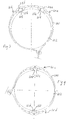
FIG. 3 is an end view of two adjacent cable tie sleeves engaged with a single cable tie in place holding two brake lines on a drive shaft, as one example of the use of the invention; and
FIG. 4 is a view similar to that of FIG. 3, but showing two non-adjacent cable tie sleeves in use holding two spaced electrical cables against a duct.
DETAILED DESCRIPTION OF THE PREFERRED EMBODIMENTS
The invention may be accomplished in a sleeve for a cable tie, in which the sleeve is removeably coupled to the cable tie and can be located essentially anywhere along the length of the tie. The sleeve carries a pair of protrusions that extend outward from the strap of the cable tie to define a recess located between the protrusions. A cable or other structure such as a motor vehicle brake line can be located in the recess. The inventive sleeve thus helps to maintain a cable, brake line or other elongated structure in place while helping to alleviate the compressive force that would otherwise be placed on the structure by the tightened cable tie.
FIGS. 1A through 1G detail the construction of the preferred embodiment of the cable tie sleeve of the invention. Sleeve 10 is adapted to be placed over a cable tie, as shown in FIGS. 2 through 4. Cable tie 90 shown in FIGS. 2A and 2B is a typical cable tie with an elongated flexible strap 96 with a locking head 94 at one end of strap 96 and tail 92 at the other end. Strap 96 carries structure that is adapted to be engaged with locking head 94 to lock cable tie 90 in a generally circular shape. In this embodiment, cable tie 90 defines a large number of closely-spaced transverse teeth 97 across most of the width of the strap, and head 94 carries locking pawl 95 that has one or more teeth that engage with teeth 97 on strap 96. The construction of cable ties is well known and need not be further described. It should be noted, however, that there are many different types of cable tie locking arrangements, and this invention can be used with many such cable ties, as will be more fully explained below.
Cable tie sleeve 10, FIGS. 1A through 1G, comprises elongated body 12 that defines an open-ended longitudinal cavity 11 that is sized and shaped to accept the strap of a cable tie. This allows the sleeve to be slipped over the end of the cable tie and moved along the length of the tie strap. Sleeve 10 carries a pair of spaced protrusions 14, 16, extending from body 12 so as to define receiving recess 15 between the protrusions. Ideally, recess 15 is sized and shaped to accept a structure that is to be held down by the cable tie with the inventive sleeve. For example, in one non-limiting embodiment, a sleeve about 2.1 inches long, 0.4 inches wide, and 0.4 inches high defines a recess cavity about 0.3 inches wide and 0.2 inches high, which is useful to maintain in place without compressing structures such as brake cables.
In the embodiment shown in these figures, each protrusion comprises a wall that extends at about 90 degrees from the sleeve body. This defines a receiving recess with essentially parallel walls. For example, protrusion 14 has generally vertical interior wall 50 and protrusion 16 has generally vertical interior wall 52. Protrusions 14 and 16 in this embodiment also comprise spaced essentially triangular side walls that give the protrusion compressive and bending strength sufficient to prevent the protrusions from being crushed by the typical cable tie compressive force accomplished by the cable tie on which the sleeve is designed to fit.
Most cable tie straps have a generally rectangular shape, dictating that longitudinal cavity 11 also be generally rectangular in cross-section. This is accomplished in the embodiment by forming elongated body 12 with two elongated generally parallel side walls 70 and 72, a top wall 74 coupled to the top edges of both of the side walls, and a bottom wall 76 coupled to the bottom edges of both of the side walls.
As cable ties take a generally circular shape when they are locked in place, the inventive sleeve needs to be able to flex or bend such that its elongated body generally follows the curvature of the portion of the cable ties strap with which the sleeve is engaged. This could be accomplished in different manners. One manner would be to make the body of a material having sufficient flexibility, perhaps a relatively low durometer material such as a silicone rubber or the like. This construction might require that the protrusions be made of a harder material, or perhaps require inclusion of stiffening structures in the protrusions, such as might be accomplished by insert molding stiffer plastic or metal pieces, perhaps.
Most cable ties are made from a tough nylon material. An inventive sleeve that is fully compatible with such ties can be made from the same material. In order to assist the inventive sleeve to bend generally along the same radius as the cable tie strap, it is desirable to place one or more relief openings in the sleeve body sidewalls. In the preferred embodiment shown in the drawings, this relief is accomplished by a series of generally triangular openings in each sidewall, in which the openings are generally aligned in the direction across the elongated cavity. This defines bending regions across the top of the elongated body. For example, side 70, FIG. 1A, includes openings 22 through 26. Side 72, FIG. 1B includes identical openings at the same locations. Only one of these openings 22 a is labeled, for the sake of clarity in the drawing. These aligned openings define bending regions across top wall 74. These bending regions are located generally at the linear areas at which the top of the triangular openings intersect the top wall of the elongated body. These areas are labeled areas 60, 62, 68, 64 and 66, FIG. 1E. In this embodiment, the bending at these areas is further enhanced by creating living hinges across the width of the top at each of these areas. This is accomplished by thinning the plastic in such areas by creating a small semi-circular molded depression in the underside the top at these areas. These depressions are visible in the cross-sectional view of FIG. 1D, with depression 60 being labeled.
Another aspect that assists in the flexibility of the inventive sleeve is constructing both the top and bottom walls of the elongated body as a series of spaced straps. Another way to look at this construction is that most of the area of the top and bottom walls is open. In fact, the top and bottom walls need only to be sufficiently structural such that they maintain the viability of the sleeve as it is used and bent. Top wall 74 in this construction comprises spaced straps 18 and 20, together with the pedestals that support protrusions 14 and 16. Bottom wall 76 comprises four straps 30, 32, 34 and 36. It is believed that the functionality of the elongated body could be achieved with a minimum of three such straps, pedestals or other connecting regions, with two on the top wall (one supporting each protrusion) and one on the bottom wall. The exact design and construction of the elongated body should be such as to allow the sleeve to be bend sufficiently so as not to substantially inhibit the functionality of the cable tie with which it is engaged, while providing the protrusions with sufficient resistance to compression to achieve the functionality of at least inhibiting, and ideally eliminating, compressive forces placed on the cable or other structure that is located in the recess of the inventive cable tie sleeve.
The preferred embodiment of the cable tie sleeve of the invention includes structure that helps to maintain the cable tie in place at the desired location along the length of the cable tie strap. In the preferred embodiment that is designed to be used with a cable tie strap having a number of transverse teeth, this objective is accomplished by including at least one series of closely-spaced, essentially parallel, inwardly-directed protrusions on the underside of the top of the sleeve. In the embodiment, two such series of spaced protrusions, 40 and 42, are included. Each such series comprises three protrusions that define between them two receiving spaces for receiving two adjacent teeth of the cable tie strap. The protrusions of series 40 and 42 are dimensioned to accomplish an interference fit with the teeth of a cable tie strap, the interference fit being able to be overcome with a longitudinal pushing or pulling force that allows the cable tie sleeve to be located at a desired point along the length of the cable tie strap, but with sufficient staying force such that the cable tie sleeve won't move along the length of the strap as the cable tie is engaged around a structure such as a duct or vehicle axle or the like.
FIGS. 3 and 4 show two of the numerous possibilities of the inventive cable tie sleeve. One aspect of these illustrations is that one or more cable tie sleeves can be placed on a cable tie. Another aspect is that the cable tie sleeves can be located where desired along the length of the cable tie strap, in order to accommodate the mounting needs being met by the cable tie sleeves. FIG. 3 shows cable tie 100 engaged around structure 102 to hold cables or brake lines 104 and 106 in place against structure 102 without crushing them. This illustration also shows that cable ties 10 a and 10 b tend to bend more at the central living hinges 24 a and 24 b, respectively, due to the fact that the construction of the elongated body is such that in the area of recesses 15 a and 15 b defined between the protrusions, both the top and bottom walls of the elongated body of the cable tie sleeves is essentially open. This makes this portion of the length of the cable tie sleeves more easily bent than the other portions of the length.
These drawings also show that this bending acts to cant the triangular protrusions toward one another at the point where they contact structure 102. This causes the shape of the receiving recess such as recess 15 a to change such that the top opening of the recess becomes effectively smaller as the sleeve is bent. This change causes the sidewalls of the recess to be generally inwardly directed such that they more closely follow the circumference of the round structures 104 and 106. The result is that for structures that generally fill the recess, the generally vertical walls of the protrusions become angled such that they can support or at least more closely restrain the sides of the cables. This construction provides additional crush resistance, as the protrusions lie generally perpendicular to the surface, thus accomplishing the greatest resistance to crushing forces.
Finally, FIG. 4 illustrates a case in which again multiple inventive cable tie sleeves are used, but this time they are spaced along the length of the cable tie strap rather than adjacent to one another to accommodate the diametrically opposed cables 108 and 110 that are held within recesses 15 c and 15 d of cable tie sleeves 10 c and 10 d, respectively.
Although features of this invention are shown in some drawings and not others, this is not a limitation of the invention, which is defined by the following claims. Also, other embodiments would be apparent to those skilled in the art from the description, and the following claims.

Claims (18)

1. A sleeve adapted to be placed over a cable tie, in which the cable tie comprises an elongated flexible strap, the sleeve comprising:
an elongated body defining a generally parallelepiped external shape and an open-ended, rectangular-shaped longitudinal cavity that is sized and shaped to accept the strap, so that the sleeve can be engaged along the length of the strap,
the elongated body comprising two parallel sidewalls, each sidewall having a rectangular shape and defining a top edge and an opposing bottom edge, a top wall coupled to the top edges of both of the sidewalls and perpendicular to the sidewalls, wherein the top wall comprises at least two spaced top straps, and a bottom wall coupled to the bottom edges of both of the sidewalls and perpendicular to the sidewalls; and
a pair of spaced protrusions, where each protrusion protrudes from the top wall and comprises a protruding wall that is perpendicular to the top wall such that the protruding walls are parallel to each other so as to define a receiving recess located between the protruding walls.
2. The sleeve of claim 1, wherein the top wall defines at least one series of closely-spaced, essentially parallel, inwardly-directed protrusions on its underside.
3. The sleeve of claim 2, wherein the elongated flexible strap of the cable tie defines spaced teeth across the width of the strap, and the inwardly-directed protrusions are spaced apart about the same distance as are the teeth, so that the sleeve releasably engages with the strap.
4. A sleeve adapted to be placed over a cable tie, in which the cable tie comprises an elongated flexible strap, the sleeve comprising:
an elongated body defining a generally parallelepiped external shape and an open-ended, rectangular-shaped longitudinal cavity that is sized and shaped to accept the strap, so that the sleeve can be engaged along the length of the strap,
the elongated body comprising two parallel sidewalls, each sidewall having a rectangular shape and defining a top edge and an opposing bottom edge, a top wall coupled to the top edges of both of the sidewalls and perpendicular to the sidewalls, and a bottom wall coupled to the bottom edges of both of the sidewalls and perpendicular to the sidewalls, wherein the bottom wall comprises two or more spaced bottom straps, and
a pair of spaced protrusions, where each protrusion protrudes from the top wall and comprises a protruding wall that is perpendicular to the top wall such that the protruding walls are parallel to each other so as to define a receiving recess located between the protruding walls.
5. A sleeve adapted to be placed over a cable tie, in which the cable tie comprises an elongated flexible strap. the sleeve comprising:
an elongated body defining a generally parallelepiped external shape and an open-ended, rectangular-shaped longitudinal cavity that is sized and shaped to accept the strap, so that the sleeve can be engaged along the length of the strap,
the elongated body comprising two parallel sidewalls, each sidewall having a rectangular shape and defining a top edge and an opposing bottom edge, wherein the sidewalls each define two or more spaced openings, a top wall coupled to the top edges of both of the sidewalls and perpendicular to the sidewalls, and a bottom wall coupled to the bottom edges of both of the sidewalls and perpendicular to the sidewalls; and
a pair of spaced protrusions, where each protrusion protrudes from the top wall and comprises a protruding wall that is perpendicular to the top wall such that the protruding walls are parallel to each other so as to define a receiving recess located between the protruding walls.
6. The sleeve of claim 5, wherein the openings are generally triangular in shape.
7. The sleeve of claim 6, wherein each of the triangular openings comprises a base, and the base of the triangular openings is at the bottom of the sidewalls.
8. The sleeve of claim 5, wherein the openings on each sidewall are generally aligned in the direction across the elongated body, to define bending regions across the top wall.
9. The sleeve of claim 8, wherein the bending regions are further defined by thinnings of the top to create living hinges in the top wall.
10. The sleeve of claim 9, wherein the living hinges are essentially perpendicular to the sidewalls.
11. The sleeve of claim 10, wherein the top wall comprises a series of spaced top straps.
12. The sleeve of claim 11, wherein the hinges are located at approximately the midpoints of the top straps.
13. A sleeve adapted to be placed over a cable tie, in which the cable tie comprises an elongated flexible strap the sleeve comprising:
an elongated body defining a generally parallelepiped external shape and an open-ended, rectangular-shaped longitudinal cavity that is sized and shaped to accept the strap, so that the sleeve can be removably engaged along the length of the strap,
the elongated body comprising two parallel sidewalls, each sidewall having a rectangular shape and defining a top edge and a bottom edge, and wherein the sidewalls each define two or more spaced openings, with the openings on each sidewall being generally aligned in the direction across the elongated body to define bending regions across the top, a top wall coupled to the edges of both the sidewalls and perpendicular to the sidewalls, and a bottom wall coupled to the bottom edges of both of the sidewalls and perpendicular to the sidewalls; and
a pair of spaced protrusions, where each protrusion protrudes from the top wall and comprises a protruding wall that is perpendicular to the top wall such that the protruding walls are parallel to each other so as to define a receiving recess located between the protrusions and the sleeve body.
14. The sleeve of claim 13, wherein the bending regions are further defined by thinnings of the top wall to create living hinges in the top wall, wherein the living hinges are essentially perpendicular to the sidewalls.
15. The sleeve of claim 14, wherein the top wall comprises a series of spaced top straps.
16. The sleeve of claim 15, wherein the hinges are located at approximately the midpoints of the top straps.
17. The sleeve of claim 16, wherein the top wall defines a series of closely-spaced, essentially parallel, inwardly-directed protrusions on its underside.
18. The sleeve of claim 17, wherein the elongated flexible strap of the cable tie defines spaced teeth across the width of the strap, and the inwardly-directed protrusions are spaced apart about the same distance as are the teeth, so that the sleeve releasably engages with the strap.
US11/861,404 2007-09-26 2007-09-26 Cable tie sleeve Expired - Fee Related US8037579B2 (en)

Priority Applications (1)

Application Number Priority Date Filing Date Title
US11/861,404 US8037579B2 (en) 2007-09-26 2007-09-26 Cable tie sleeve

Applications Claiming Priority (1)

Application Number Priority Date Filing Date Title
US11/861,404 US8037579B2 (en) 2007-09-26 2007-09-26 Cable tie sleeve

Publications (2)

Publication Number Publication Date
US20090077772A1 US20090077772A1 (en) 2009-03-26
US8037579B2 true US8037579B2 (en) 2011-10-18

Family

ID=40470145

Family Applications (1)

Application Number Title Priority Date Filing Date
US11/861,404 Expired - Fee Related US8037579B2 (en) 2007-09-26 2007-09-26 Cable tie sleeve

Country Status (1)

Country Link
US (1) US8037579B2 (en)

Cited By (2)

* Cited by examiner, † Cited by third party
Publication number Priority date Publication date Assignee Title
US10259627B2 (en) 2017-05-11 2019-04-16 Marking Services Incorporated Fastening system
US10435214B2 (en) 2017-01-04 2019-10-08 Brian Kuperus Tie-wrap assembly and method for using the same

Families Citing this family (5)

* Cited by examiner, † Cited by third party
Publication number Priority date Publication date Assignee Title
US20100212117A1 (en) * 2009-02-25 2010-08-26 Haase Edward A Compostable Tie
EP2499412B1 (en) 2009-11-09 2014-09-24 Federal-Mogul Powertrain, Inc. Low profile, wrappable elongate members spacer and method of maintaining elongate members in fixed, spaced relative relation
US20120168473A1 (en) * 2011-01-05 2012-07-05 GamePlan Gear LLC Pack strap
US20180187703A1 (en) * 2017-01-04 2018-07-05 Brian Kuperus Tie-wrap assembly and method for using the same
GB2593896A (en) * 2020-04-06 2021-10-13 Ellis Patents Holdings Ltd Retaining apparatus

Citations (18)

* Cited by examiner, † Cited by third party
Publication number Priority date Publication date Assignee Title
US3197829A (en) * 1962-03-08 1965-08-03 Panduit Corp Binder strap
US3384700A (en) * 1966-04-19 1968-05-21 Christopher W. Mier Splice insulating device of the heavy duty type
US3762585A (en) * 1972-08-11 1973-10-02 Witt C Hobbs Trustee De Adjustable spacer block system for use in towing vehicles
US5263231A (en) 1991-08-20 1993-11-23 Sorensen Soren C Cable tie with hollow pawl sections
US5440786A (en) 1993-06-04 1995-08-15 Sorensen; Soren C. Injection molding of cable ties with a mold having an enhanced core section
US5615455A (en) 1995-12-28 1997-04-01 Gb Electrical, Inc. Cable tie having enhanced abutment wall in locking head
US5964013A (en) 1997-12-09 1999-10-12 Bergstrom; John A Cable tie with cable protection features
US6128809A (en) 1997-12-01 2000-10-10 Thomas & Betts International, Inc. Cable tie having a locking head and a separate strap
US6311935B1 (en) 1999-07-07 2001-11-06 Heyco Products, Inc. Cable clamp
US6499199B2 (en) * 2000-07-16 2002-12-31 Mark Frazier Bundling device for a length of line type material
US20040006852A1 (en) * 2000-09-21 2004-01-15 Castro Andrea De Lima Pull-tight one-piece security seal, adapted for the closure of bags or the like
US6698069B2 (en) * 2001-05-15 2004-03-02 Panduit Corp. Low profile cable tie with prebent strap
US20040045134A1 (en) * 2001-02-08 2004-03-11 Savicki Alan F. Closure device
US6895641B1 (en) * 1999-06-10 2005-05-24 The Glad Products Company Closure device
US20060053753A1 (en) * 2002-11-13 2006-03-16 Jae-Ho Ha Pack sealing method and device
US7107653B2 (en) * 2002-02-08 2006-09-19 Dt Search & Design Cable retention device
US7127779B2 (en) * 2004-12-15 2006-10-31 Advanced Cable Ties, Inc. Cable tie
US7263745B2 (en) * 2005-08-02 2007-09-04 Kenji Mori Binding band

Patent Citations (18)

* Cited by examiner, † Cited by third party
Publication number Priority date Publication date Assignee Title
US3197829A (en) * 1962-03-08 1965-08-03 Panduit Corp Binder strap
US3384700A (en) * 1966-04-19 1968-05-21 Christopher W. Mier Splice insulating device of the heavy duty type
US3762585A (en) * 1972-08-11 1973-10-02 Witt C Hobbs Trustee De Adjustable spacer block system for use in towing vehicles
US5263231A (en) 1991-08-20 1993-11-23 Sorensen Soren C Cable tie with hollow pawl sections
US5440786A (en) 1993-06-04 1995-08-15 Sorensen; Soren C. Injection molding of cable ties with a mold having an enhanced core section
US5615455A (en) 1995-12-28 1997-04-01 Gb Electrical, Inc. Cable tie having enhanced abutment wall in locking head
US6128809A (en) 1997-12-01 2000-10-10 Thomas & Betts International, Inc. Cable tie having a locking head and a separate strap
US5964013A (en) 1997-12-09 1999-10-12 Bergstrom; John A Cable tie with cable protection features
US6895641B1 (en) * 1999-06-10 2005-05-24 The Glad Products Company Closure device
US6311935B1 (en) 1999-07-07 2001-11-06 Heyco Products, Inc. Cable clamp
US6499199B2 (en) * 2000-07-16 2002-12-31 Mark Frazier Bundling device for a length of line type material
US20040006852A1 (en) * 2000-09-21 2004-01-15 Castro Andrea De Lima Pull-tight one-piece security seal, adapted for the closure of bags or the like
US20040045134A1 (en) * 2001-02-08 2004-03-11 Savicki Alan F. Closure device
US6698069B2 (en) * 2001-05-15 2004-03-02 Panduit Corp. Low profile cable tie with prebent strap
US7107653B2 (en) * 2002-02-08 2006-09-19 Dt Search & Design Cable retention device
US20060053753A1 (en) * 2002-11-13 2006-03-16 Jae-Ho Ha Pack sealing method and device
US7127779B2 (en) * 2004-12-15 2006-10-31 Advanced Cable Ties, Inc. Cable tie
US7263745B2 (en) * 2005-08-02 2007-09-04 Kenji Mori Binding band

Cited By (3)

* Cited by examiner, † Cited by third party
Publication number Priority date Publication date Assignee Title
US10435214B2 (en) 2017-01-04 2019-10-08 Brian Kuperus Tie-wrap assembly and method for using the same
US10882674B2 (en) 2017-01-04 2021-01-05 Brian Kuperus Tie-wrap assembly and method for using the same
US10259627B2 (en) 2017-05-11 2019-04-16 Marking Services Incorporated Fastening system

Also Published As

Publication number Publication date
US20090077772A1 (en) 2009-03-26

Similar Documents

Publication Publication Date Title
US8037579B2 (en) Cable tie sleeve
US8119914B2 (en) Substantially transparent cable protector and cable protection system
US5820048A (en) Side latching hinge mechanism
AU2006224441B2 (en) Splice plate for a wire cable tray
US7394025B1 (en) Apparatus for protecting cables or other elongated objects from traffic damage
US4358080A (en) Fastener clip for detachably securing functional components to threaded pins fixed to a support plate
EP1708328A2 (en) Protector
US7507905B2 (en) Electrical junction box
US6751382B2 (en) System for organizing wires and cables
EP1369630B1 (en) Cinch strap
JP3421261B2 (en) Improved cable tie with locking head and separate strap
EP2302749A1 (en) Wire harness routing structure and wire harness flattening band
JP4403987B2 (en) Protector for inserting wire harness
US11027902B2 (en) Integrated release feature for pawl-latching devices
US20060219421A1 (en) Cable or the like protection and guide device
CA2416415C (en) Locking strap with handling structure
CN110125979A (en) Filament fixes device
KR20130020770A (en) Block body for connecting cable protection pipe, and connecting structure of cable protection pipe
US6938305B2 (en) Electrical assembly including an electrical tie
JP5075547B2 (en) In-vehicle protector
US10144566B2 (en) High strength cable tie arrangement
EP3688357B1 (en) Cable clips
WO2006121311A1 (en) Cable tie
US6007051A (en) Wire duct wiring tool
JP7234070B2 (en) Binding structure of routing material

Legal Events

Date Code Title Description
AS Assignment

Owner name: ADVANCED CABLE TIES, INC., MASSACHUSETTS

Free format text: ASSIGNMENT OF ASSIGNORS INTEREST;ASSIGNOR:TOMASETTI, KENNETH;REEL/FRAME:026931/0094

Effective date: 20110824

AS Assignment

Owner name: ADVANCED CABLE TIES, INC., MASSACHUSETTS

Free format text: CORRECTIVE ASSIGNMENT TO CORRECT THE ASSIGNEE STATE OF INCORPORATION INSIDE ASSIGNMENT DOCUMENT PREVIOUSLY RECORDED AT REEL: 026931 FRAME: 0094. ASSIGNOR(S) HEREBY CONFIRMS THE ASSIGNMENT;ASSIGNOR:TOMASETTI, KENNETH;REEL/FRAME:034523/0596

Effective date: 20110824

REMI Maintenance fee reminder mailed
AS Assignment

Owner name: UNIBANK FOR SAVINGS, MASSACHUSETTS

Free format text: SECURITY INTEREST;ASSIGNOR:ADVANCED CABLE TIES, INC.;REEL/FRAME:036151/0050

Effective date: 20150715

LAPS Lapse for failure to pay maintenance fees
STCH Information on status: patent discontinuation

Free format text: PATENT EXPIRED DUE TO NONPAYMENT OF MAINTENANCE FEES UNDER 37 CFR 1.362

FP Expired due to failure to pay maintenance fee

Effective date: 20151018