US8038878B2 - Integrated filter system for a coolant reservoir and method - Google Patents
Integrated filter system for a coolant reservoir and method Download PDFInfo
- Publication number
- US8038878B2 US8038878B2 US12/626,659 US62665909A US8038878B2 US 8038878 B2 US8038878 B2 US 8038878B2 US 62665909 A US62665909 A US 62665909A US 8038878 B2 US8038878 B2 US 8038878B2
- Authority
- US
- United States
- Prior art keywords
- coolant
- chamber
- filter element
- cup
- depression
- Prior art date
- Legal status (The legal status is an assumption and is not a legal conclusion. Google has not performed a legal analysis and makes no representation as to the accuracy of the status listed.)
- Active, expires
Links
- 239000002826 coolant Substances 0.000 title claims abstract description 115
- 238000000034 method Methods 0.000 title description 6
- 238000001816 cooling Methods 0.000 claims abstract description 16
- 239000012530 fluid Substances 0.000 claims description 24
- 239000011800 void material Substances 0.000 claims description 10
- 238000004891 communication Methods 0.000 claims description 9
- 239000002245 particle Substances 0.000 claims description 6
- 238000009434 installation Methods 0.000 claims description 5
- 238000003860 storage Methods 0.000 claims description 5
- 239000000356 contaminant Substances 0.000 abstract description 12
- 238000001914 filtration Methods 0.000 abstract description 8
- 239000007788 liquid Substances 0.000 abstract description 6
- 238000002485 combustion reaction Methods 0.000 description 8
- 239000000243 solution Substances 0.000 description 5
- 238000003466 welding Methods 0.000 description 5
- 239000000463 material Substances 0.000 description 4
- 238000010276 construction Methods 0.000 description 2
- 238000007872 degassing Methods 0.000 description 2
- 230000005484 gravity Effects 0.000 description 2
- 230000008569 process Effects 0.000 description 2
- 239000002918 waste heat Substances 0.000 description 2
- 230000009471 action Effects 0.000 description 1
- 230000003466 anti-cipated effect Effects 0.000 description 1
- 238000006243 chemical reaction Methods 0.000 description 1
- 230000000694 effects Effects 0.000 description 1
- 238000001704 evaporation Methods 0.000 description 1
- 230000008020 evaporation Effects 0.000 description 1
- 238000001746 injection moulding Methods 0.000 description 1
- 229910052500 inorganic mineral Inorganic materials 0.000 description 1
- JEIPFZHSYJVQDO-UHFFFAOYSA-N iron(III) oxide Inorganic materials O=[Fe]O[Fe]=O JEIPFZHSYJVQDO-UHFFFAOYSA-N 0.000 description 1
- 239000000314 lubricant Substances 0.000 description 1
- 238000004519 manufacturing process Methods 0.000 description 1
- 230000013011 mating Effects 0.000 description 1
- 239000011707 mineral Substances 0.000 description 1
- 238000012986 modification Methods 0.000 description 1
- 230000004048 modification Effects 0.000 description 1
- 239000002244 precipitate Substances 0.000 description 1
- 230000007704 transition Effects 0.000 description 1
Images


Classifications
-
- F—MECHANICAL ENGINEERING; LIGHTING; HEATING; WEAPONS; BLASTING
- F01—MACHINES OR ENGINES IN GENERAL; ENGINE PLANTS IN GENERAL; STEAM ENGINES
- F01P—COOLING OF MACHINES OR ENGINES IN GENERAL; COOLING OF INTERNAL-COMBUSTION ENGINES
- F01P11/00—Component parts, details, or accessories not provided for in, or of interest apart from, groups F01P1/00 - F01P9/00
- F01P11/02—Liquid-coolant filling, overflow, venting, or draining devices
- F01P11/029—Expansion reservoirs
-
- B—PERFORMING OPERATIONS; TRANSPORTING
- B01—PHYSICAL OR CHEMICAL PROCESSES OR APPARATUS IN GENERAL
- B01D—SEPARATION
- B01D35/00—Filtering devices having features not specifically covered by groups B01D24/00 - B01D33/00, or for applications not specifically covered by groups B01D24/00 - B01D33/00; Auxiliary devices for filtration; Filter housing constructions
- B01D35/02—Filters adapted for location in special places, e.g. pipe-lines, pumps, stop-cocks
- B01D35/027—Filters adapted for location in special places, e.g. pipe-lines, pumps, stop-cocks rigidly mounted in or on tanks or reservoirs
-
- F—MECHANICAL ENGINEERING; LIGHTING; HEATING; WEAPONS; BLASTING
- F01—MACHINES OR ENGINES IN GENERAL; ENGINE PLANTS IN GENERAL; STEAM ENGINES
- F01P—COOLING OF MACHINES OR ENGINES IN GENERAL; COOLING OF INTERNAL-COMBUSTION ENGINES
- F01P11/00—Component parts, details, or accessories not provided for in, or of interest apart from, groups F01P1/00 - F01P9/00
- F01P11/06—Cleaning; Combating corrosion
-
- Y—GENERAL TAGGING OF NEW TECHNOLOGICAL DEVELOPMENTS; GENERAL TAGGING OF CROSS-SECTIONAL TECHNOLOGIES SPANNING OVER SEVERAL SECTIONS OF THE IPC; TECHNICAL SUBJECTS COVERED BY FORMER USPC CROSS-REFERENCE ART COLLECTIONS [XRACs] AND DIGESTS
- Y10—TECHNICAL SUBJECTS COVERED BY FORMER USPC
- Y10T—TECHNICAL SUBJECTS COVERED BY FORMER US CLASSIFICATION
- Y10T137/00—Fluid handling
- Y10T137/794—With means for separating solid material from the fluid
Definitions
- the present invention relates to a coolant reservoir for an internal combustion engine and, more particularly, to a coolant reservoir having an integrated coolant filtering system for removal of particulate contaminants from the coolant.
- Liquid coolant systems are typically provided to remove this waste heat from the internal combustion engine to reduce operating temperature and to extend the life of mechanical parts and lubricants.
- coolant reservoir tanks on liquid cooling systems, particularly cooling systems for internal combustion engines. Such reservoir tanks provide a surplus supply of coolant in reserve to compensate for inevitable minor leaks and evaporation. Coolant reservoir tanks additionally provide surge capacity for the storage of liquid coolant during engine operation.
- the volume of liquid coolants varies in relation to changes in coolant temperature. As the engine warms the coolant typically expands in volume. In such cases the coolant reservoir provides fluid storage capacity to accommodate this coolant surge while keeping it ready to return back to the coolant system when engine operation ceases.
- coolant necessarily flows between the coolant reservoir and the remaining coolant system due to changes in operating conditions of the engine, such as operating temperature changes and engine start/stop transitions.
- particulate contaminants may become entrained into the coolant.
- Such particulate contaminants may include, for example, rust or scale from coolant passages in the engine, dissolved minerals which may precipitate from the coolant, contaminants formed from chemical reactions between various fluid and engine system components, gasket materials, metallic and plastic debris resulting from mechanical wear of rotating or moving components into which the coolant comes into contact, as well as other causes.
- a cooling system for an internal combustion engine includes a degassing line between the engine and coolant reservoir tank.
- a disposable filter is provided in the degassing line to filter coolant transitioning between the coolant system and the reservoir.
- the filter housing and filter element are not integrated internally into the coolant reservoir, and the solution is unnecessarily complex to manufacture and therefore unnecessarily costly.
- a coolant filtering solution is taught by PCT Publication number WO 00/06874.
- a coolant system for an internal combustion engine including a radiator, a pump to circulate the coolant, a thermostatically operated bypass valve and a coolant reservoir equipped with a removable pleated cartridge assembly.
- the filter cartridge assembly is unnecessarily complex in materials and construction, resulting in an unnecessary higher cost and complex solution.
- a filtered reservoir system for a cooling system includes a coolant reservoir having at least a first chamber and at least one second chamber with an interior wall substantially separating the first and second chambers. Coolant overflowing from an engine cooling system is directed to enter the first chamber.
- a cap member having a first engagement member is provided.
- a mounting member having a sleeve-like wall and a central aperture is sized and configured to receive a replaceable filter element within the central aperture.
- the sleeve-like wall includes a complimentary second engagement member configured and adapted for removeably mounting the cap member to the mounting member so as to close out the central aperture and form a cup-like depression.
- the mounting member protrudes downwards from a bottom wall of the reservoir to form the cup-like depression under the interior wall.
- the cup-like depression has a first portion in fluid communication with the first chamber and a second portion in fluid communication with the second chamber.
- a replaceable filter element configured to mount into the central aperture of the mounting member and adapted to filter particulates from coolant passing through the cup-like depression from the coolant flowing between the first and second chambers.
- the filter element includes a mounting flange sized and configured to abut against the sleeve-like wall, a support body having an interior void and secured at a first end to the mounting flange with the support body extending upwards into the second chamber and having at least one outlet aperture and at least one inlet aperture.
- the outlet and inlet apertures extend through the support body into the interior void.
- the filter element further includes at least one filter media member secured in the interior void and occluding the outlet apertures such that coolant exiting the outlet apertures must be filtered by the filter media member.
- the support body of the filter element has a planar first surface aligned with and abutting the interior wall. The first surface cooperates with the interior wall to provide fluid closure between the first and second chambers such that fluid flow through the cup-like depression between the first and second chambers is constrained to flow through the filter media.
- the cooling system is configured to direct overflow coolant into the first chamber and the second chamber provides storage capacity for the overflow coolant.
- a bypass passage is provided between the first and second chambers.
- the bypass passage is configured to permit fluid to bypass the filter element in the event the filter element becomes blocked.
- the bypass passage is positioned to define a second depression above the cup-like depression that is operative to entrap heavier particles from the coolant before they can pass from the first chamber to the second chamber.
- the central aperture of the mounting member is generally circular and the support body has a generally semi-circular cross section.
- the interior wall is offset from an axial center of the central aperture such that the first portion of the cup-like portion is larger than the second portion of the cup-like portion.
- the support body is sized to be received into the second portion of the cup-like depression. This offset enforces correct axial alignment of the filter element in the mounting member during installation of the filter element.
- the outlet apertures are positioned above the bottom wall and within the second chamber.
- the sleeve-like wall includes a recess configured to receive the mounting flange of the support body.
- the mounting flange installs into the sleeve-like wall in a flush fashion and an annular seal member is provided to form a fluid seal between the sleeve-like member, the mounting flange and the cap member.
- FIG. 1 illustrates one embodiment of a replaceable coolant filter element having a hollow support body and an annular ring-like mounting flange, consistent with the present invention
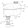
- FIG. 2 illustrates a filtered reservoir system with a coolant reservoir having an integrated replaceable coolant filter element, consistent with the present invention
- FIG. 3 provides a sectional side view of a portion of the filtered reservoir system depicted in FIG. 2 , illustrating internal features of the present invention.
- the present invention generally provides an advantageously simple, low cost, replaceable coolant filtering system which is integrated in a coolant reservoir bottle or reservoir tank of an internal combustion engine liquid cooling system.
- the coolant filtering system intercepts coolant flowing between the engine cooling system and the coolant reservoir, removing particulates from the coolant by filtration, entrapping the removed particulates on the filter media as well as capturing larger particulates into a drainable cup-like depression provided within the coolant reservoir.
- the present invention also provides a coolant bypass passage operative to permit coolant to bypass the integrated filter should the filter media become blocked with contaminants.
- the bypass passage is positioned at an elevated location and cooperates with the cup-like depression to still permit heavier or larger particles to drop into the drainable cup-like depression when the filter is blocked, thereby removing a portion of the particulate contaminants from the coolant even when the coolant filter is blocked.
- FIG. 1 illustrates one embodiment of a replaceable coolant filter element 11 having an annular ring-like mounting flange 42 , consistent with the present invention.
- a support body 44 is secured at one end to the mounting flange 42 and extends generally upwards.
- a fluid passage or void 46 is provided in the support body and extends between an inlet aperture 50 of the filter element 11 and filter media members 54 .
- Filter media members 54 are secured to the support body 44 and occlude the outlet apertures 48 of the filter element 11 such that any coolant flowing between the inlet aperture 50 and the outlet apertures 48 is constrained to pass through the filter media members 54 , thereby removing particulates from the coolant.
- FIG. 2 illustrates a filtered reservoir system 10 including a coolant reservoir 12 integrated with a replaceable coolant filter element 11 , consistent with the present invention.
- FIG. 3 is a sectional side view of a portion of the filtered reservoir system 10 depicted in FIG. 2 .
- Coolant reservoir 12 has an upper housing portion 76 and a lower housing portion 78 that are permanently and closeably secured along complimentary mating flanges 80 to form a unitary reservoir 12 .
- the housing portions 76 and 78 may be formed from a suitable plastic material by way of an injection molding process or using other materials and processes as would be known to those skilled in the art.
- Upper portion 76 and lower portion 78 may be secured by a suitable welding process such as hot plate welding, friction welding, ultrasonic welding, laser or IR welding to name a few examples.
- An inlet tube 62 is operatively connected to deliver surge flows or overflow of coolant from an internal combustion engine cooling system (not shown) to the coolant reservoir 12 .
- a coolant return line 64 or outlet tube is operatively connected to deliver coolant back into the engine cooling system (not shown) when makeup coolant is required.
- a fill neck 66 is provided on an upper portion of the coolant reservoir 12 .
- the fill neck 66 may be provided with external threads or other engagement means to removeably mount a pressure cap or other closure cap (not shown) onto the fill neck 66 .
- a mounting member 22 is provided on a bottom wall 32 of the coolant reservoir 12 .
- the mounting member has a sleeve-like wall 24 surrounding a central aperture 30 that is sized and configured to receive a portion of the replaceable filter element 11 therein.
- a cap member 20 is provided to removeably secure the filter element 11 within the central aperture 30 .
- the cap member 20 includes engagement means, for example, threads sized and configured to removeably engage with complimentary engagement means provided on the outer wall of the mounting member 22 .
- Annular gasket 68 is sized and configured to provide a fluid seal between the mounting member 22 , filter element flange 42 and the cap member 20 .
- the central aperture 30 of the mounting member 22 is closed-off by cap member 20 and an annular gasket or seal member 68 , forming a cup-like depression 34 under the interior wall 18 and below the bottom wall 32 of the reservoir.
- the filter element 11 installed into the central aperture 30 divides the cup-like member in a first portion 36 and a second portion 38 .
- the first portion 36 is in fluid communication with the first chamber 14
- the second portion 38 is in fluid communication with a second chamber 16 of reservoir 12 .
- Coolant enters the coolant reservoir 12 through the inlet tube or vent line 62 and is received into the first chamber 14 (see FIG. 3 ) of the coolant reservoir 12 .
- the fluid is constrained to flow through the filter element 11 as shown by arrow 70 .
- Fluid flows downwards as shown by arrow 70 into the cup-like depression 34 and enters the inlet aperture 50 and void 46 of the filter element 11 .
- coolant flows upwards in the void 46 as shown by arrow 72 to intercept and be filtered through filter media members 54 , thereby entering the second chamber 16 .
- Particulates having a smaller size and lighter weight may aggregate at the filter media 54 , while heavier particulates may tend to accumulate in the first 36 and second 38 portions of the cup-like depression 34 and within the void 46 in the support body 44 , advantageously not reaching and occluding the filter media members 54 .
- Filtered coolant exits the filter element 11 into the second chamber 16 as shown by arrows 52 .
- the second chamber 16 is in fluid communication with the remainder of the coolant reservoir 12 , providing storage capacity for the overflow coolant from the engine cooling system (not shown).
- the support body 44 of the filter element 11 has a planar first surface 56 aligned and shaped to abut the interior wall 18 separating the first 14 and second 16 chambers. Due to its configuration, the planar first surface 56 that operates to effectively extend the interior wall 18 downwards and provide a substantial fluid seal between the first portion 36 and second portion 38 , thereby preventing coolant from passing between the first chamber 14 and second chamber 16 in what would otherwise be a gap between the support body 44 and the interior wall 18 .
- particulates accumulate within the cup-like depression 34 and are blocked from entering the second chamber 16 as well as remaining portions of the reservoir 12 by the filter element 11 .
- Accumulated particulates and debris in the cup-like depression 34 are drainable from the reservoir 12 when the cap member 20 is removed from the mounting member 22 , such as when replacement of the filter element 11 is performed.
- a bypass passage 58 is provided at an elevated location on the interior wall 18 to permit coolant to bypass the filter element 11 should the filter media 54 become blocked. Due to its elevated location, the bypass passage 58 defines a second depression 60 in the first chamber 14 positioned under the bypass passage 58 . This second depression 60 is operative due to the effect of gravity on heavier particles, entrapping heavier particles in the coolant before they can enter the second chamber 16 through the bypass passage 58 . Due to the shape of the second chamber, assisted by the action of gravity, these heavier particles tend to drop downwards from the second chamber in the second depression 60 and accumulate into the cup-like depression 34 where they may be later drained as discussed earlier.
- the central aperture 30 of the mounting member 22 is generally circular in cross section, for example, with a cylindrical shape, as this shape generally agrees with a mounting member equipped with threads for a threaded removable cap member 20 .
- the support body 44 of the filter element 11 is shaped such that it has a generally semi-circular cross section.
- the interior wall 18 is positioned offset from an axial center 74 such that the first portion 36 of the cup-like depression 34 is larger in size than the second portion 38 of the cup-like depression 34 , providing a support body 44 having a dimension D 1 larger than a radius R of the cup-like depression 34 , thereby enforcing proper axial alignment of the filter element 11 into the mounting member 22 during installation.
- Proper axial alignment is with the support body 44 extending upwards into the second chamber 16 and the planar first surface 56 abutting and closing against the interior wall 18 .
- the outlet apertures 48 are preferably positioned at an end of the support body opposing the flange 42 and positioned above the bottom wall 32 into the interior of the second chamber 16 .
- the method is practiced by first providing a coolant reservoir having a filter element installed into a cup-like depression extending below a bottom wall of the reservoir.
- the cup-like depression and said filter element being operable to capture particulates from the coolant.
- a removable cap is provided on the cup-like depression.
- the cap is operable to drain the captured coolant particulates and to also provide access into the reservoir for replacement of the filter element.
- a flow of coolant is introduced into the first chamber of a coolant reservoir.
- the flow of coolant between a first inlet chamber of the reservoir and a second chamber of the reservoir is constrained to pass through the filter element.
- the filter element filters the coolant flowing between the first and second chambers in the filter element, thereby removing particulate contaminants from the coolant.
- a bypass passage is provided at an elevated position in the first chamber. This elevated position forms a second depression also adapted for capturing particulates in the coolant.
- coolant then flows through the second passage. Heavier particulates accumulate in the second depression and migrate towards the first depression.
Abstract
Description
Claims (7)
Priority Applications (1)
| Application Number | Priority Date | Filing Date | Title |
|---|---|---|---|
| US12/626,659 US8038878B2 (en) | 2008-11-26 | 2009-11-26 | Integrated filter system for a coolant reservoir and method |
Applications Claiming Priority (2)
| Application Number | Priority Date | Filing Date | Title |
|---|---|---|---|
| US11799608P | 2008-11-26 | 2008-11-26 | |
| US12/626,659 US8038878B2 (en) | 2008-11-26 | 2009-11-26 | Integrated filter system for a coolant reservoir and method |
Publications (2)
| Publication Number | Publication Date |
|---|---|
| US20100132817A1 US20100132817A1 (en) | 2010-06-03 |
| US8038878B2 true US8038878B2 (en) | 2011-10-18 |
Family
ID=42221704
Family Applications (1)
| Application Number | Title | Priority Date | Filing Date |
|---|---|---|---|
| US12/626,659 Active 2030-04-20 US8038878B2 (en) | 2008-11-26 | 2009-11-26 | Integrated filter system for a coolant reservoir and method |
Country Status (1)
| Country | Link |
|---|---|
| US (1) | US8038878B2 (en) |
Cited By (16)
| Publication number | Priority date | Publication date | Assignee | Title |
|---|---|---|---|---|
| US20050274676A1 (en) * | 2004-06-10 | 2005-12-15 | Mukesh Kumar | Deionization filter for fuel cell vehicle coolant |
| US20100050623A1 (en) * | 2008-08-26 | 2010-03-04 | O'brien Ii James A | Hoseless hydraulic system |
| US20110056875A1 (en) * | 2008-03-04 | 2011-03-10 | Gerhard Stehle | Filter apparatus and filter element for such a filter apparatus |
| US20120031900A1 (en) * | 2010-08-05 | 2012-02-09 | Control Solution LLC | Bladderless reservoir tank for a hydraulic accumulator |
| US20120125564A1 (en) * | 2009-07-28 | 2012-05-24 | Shengjun Jia | Coolant temperature controlling system for engine performance test |
| US20140103047A1 (en) * | 2012-10-15 | 2014-04-17 | Mann+Hummel Gmbh | Reservoir for reducing aeration of a fluid |
| US20150041414A1 (en) * | 2013-08-09 | 2015-02-12 | Ledwell & Son Enterprises, Inc. | Hydraulic fluid cooler and filter |
| US20160222869A1 (en) * | 2015-01-29 | 2016-08-04 | Hitachi Construction Machinery Co., Ltd. | Expansion Tank |
| EP3132928A1 (en) | 2015-08-18 | 2017-02-22 | Goodrich Corporation | High thermal conductivity layer for fire resistant wood veneer |
| US20170274758A1 (en) * | 2016-03-28 | 2017-09-28 | Hyundai Motor Company | Reservoir tank of hybid vehicle |
| US20180370352A1 (en) * | 2017-06-21 | 2018-12-27 | Chongqing Baike Dingyu Technology Co., Ltd. | Safety spill-proof fuel tank structure |
| US10744428B2 (en) * | 2015-03-11 | 2020-08-18 | Mann+Hummel Gmbh | Filter element |
| US10881987B2 (en) | 2018-07-06 | 2021-01-05 | Eric Amato | Vortex reservoir |
| US11098621B2 (en) * | 2017-07-28 | 2021-08-24 | Ford Global Technologies, Llc | Oil sump assembly with an integrated oil filter |
| US11224830B2 (en) * | 2018-08-15 | 2022-01-18 | Mann+Hummel Gmbh | Conical filter element with funnel directing particles to a trap |
| US11825974B1 (en) * | 2020-03-01 | 2023-11-28 | Michael O. Murphy | Expandable strainer insert for bottles |
Families Citing this family (12)
| Publication number | Priority date | Publication date | Assignee | Title |
|---|---|---|---|---|
| US8038878B2 (en) * | 2008-11-26 | 2011-10-18 | Mann+Hummel Gmbh | Integrated filter system for a coolant reservoir and method |
| EP2564974B1 (en) | 2011-09-05 | 2015-06-17 | ALLTEC Angewandte Laserlicht Technologie Gesellschaft mit beschränkter Haftung | Marking apparatus with a plurality of gas lasers with resonator tubes and individually adjustable deflection means |
| ES2530069T3 (en) | 2011-09-05 | 2015-02-26 | ALLTEC Angewandte Laserlicht Technologie Gesellschaft mit beschränkter Haftung | Marking apparatus with a plurality of lasers and a combination deflection device |
| DK2565673T3 (en) | 2011-09-05 | 2014-01-06 | Alltec Angewandte Laserlicht Technologie Gmbh | Device and method for marking an object by means of a laser beam |
| EP2565996B1 (en) * | 2011-09-05 | 2013-12-11 | ALLTEC Angewandte Laserlicht Technologie Gesellschaft mit beschränkter Haftung | Laser device with a laser unit, and a fluid container for a cooling means of said laser unit |
| EP2564972B1 (en) | 2011-09-05 | 2015-08-26 | ALLTEC Angewandte Laserlicht Technologie Gesellschaft mit beschränkter Haftung | Marking apparatus with a plurality of lasers, deflection means and telescopic means for each laser beam |
| ES2452529T3 (en) | 2011-09-05 | 2014-04-01 | ALLTEC Angewandte Laserlicht Technologie Gesellschaft mit beschränkter Haftung | Laser device and procedure for marking an object |
| ES2544034T3 (en) | 2011-09-05 | 2015-08-27 | ALLTEC Angewandte Laserlicht Technologie Gesellschaft mit beschränkter Haftung | Marking apparatus with at least one gas laser and one thermodisipator |
| DK2564975T3 (en) | 2011-09-05 | 2015-01-12 | Alltec Angewandte Laserlicht Technologie Ges Mit Beschränkter Haftung | Selection apparatus with a plurality of lasers and sets of deflecting agents that can be individually adjusted |
| CN107664059A (en) * | 2017-10-26 | 2018-02-06 | 宁波舜江汽车部件制造有限公司 | A kind of automobile cooling compensator |
| GB2573274A (en) * | 2018-04-17 | 2019-11-06 | Caterpillar Inc | Filter for an accumulator |
| DE102019125123A1 (en) * | 2019-09-18 | 2021-03-18 | Bayerische Motoren Werke Aktiengesellschaft | Expansion tank for a temperature control circuit and vehicle assembly with a temperature control circuit |
Citations (96)
| Publication number | Priority date | Publication date | Assignee | Title |
|---|---|---|---|---|
| US2488806A (en) * | 1948-06-21 | 1949-11-22 | Clarence E Crowder | Radiator filter |
| US2672853A (en) * | 1952-04-18 | 1954-03-23 | Joseph L Dunnigan | Sealed cooling system for internalcombustion engines |
| US3214023A (en) * | 1962-04-04 | 1965-10-26 | Int Harvester Co | Hydraulic reservoir and filter |
| US3330439A (en) * | 1964-07-17 | 1967-07-11 | Gen Motors Corp | Plastic fuel tank structure |
| US3726262A (en) * | 1970-12-09 | 1973-04-10 | White Motor Corp | Engine cooling system |
| US3752222A (en) * | 1971-11-18 | 1973-08-14 | J Olbermann | Transmission oil cooling system |
| US3757984A (en) * | 1971-08-16 | 1973-09-11 | Fre Bar Inc | Cooling system container |
| US4033872A (en) * | 1974-11-08 | 1977-07-05 | Nissan Motor Co., Ltd. | Reservoir tank |
| US4185750A (en) * | 1977-12-20 | 1980-01-29 | Girling Limited | Reservoirs for master cylinders |
| US4210176A (en) * | 1978-09-14 | 1980-07-01 | J. I. Case Company | Hydraulic liquid reservoir with internal baffle |
| US4241578A (en) * | 1979-06-18 | 1980-12-30 | Eaton Corporation | Fluid storage tank for an industrial vehicle |
| US4325678A (en) * | 1979-12-12 | 1982-04-20 | Hitachi, Ltd. | Hydraulic pressure producing system for a hydraulic press |
| US4343353A (en) * | 1980-11-26 | 1982-08-10 | John Tsopelas | Automobile radiator filter |
| US4424829A (en) * | 1982-04-12 | 1984-01-10 | General Motors Corporation | Vehicle fluid power system reservoir |
| US4431027A (en) * | 1981-04-21 | 1984-02-14 | General Motors Corporation | Reservoir for remote fluid system |
| US4461342A (en) * | 1982-04-29 | 1984-07-24 | Avrea Walter C | Method and apparatus for automatically refilling a leaking liquid cooling system as an engine operates by utilizing a radiator and a remote coolant reservoir |
| US4473037A (en) * | 1982-07-15 | 1984-09-25 | Bayerische Motoren Werke A.G. | Cooling circuit for internal combustion engines |
| US4480598A (en) * | 1983-09-22 | 1984-11-06 | William C. Neils | Coolant recovery and de-aeration system for liquid-cooled internal combustion engines |
| US4527709A (en) * | 1983-06-23 | 1985-07-09 | Aisin Seiki Kabushiki Kaisha | Reservoir assembly |
| US4625777A (en) * | 1984-11-17 | 1986-12-02 | General Motors Corporation | Fuel tank ventilating system |
| USRE32434E (en) * | 1982-04-29 | 1987-06-09 | Method and apparatus for automatically refilling a leaking liquid cooling system as an engine operates by utilizing a radiator and a remote coolant reservoir | |
| US4677943A (en) * | 1986-03-03 | 1987-07-07 | Skinner Alan A | Automotive non-pressure cooling system |
| US4723596A (en) * | 1984-08-16 | 1988-02-09 | Bayerische Motoren Werke A.G. | Expansion-, deaeration and reservoir tank for the liquid-cooling system of internal combustion engines |
| US4738228A (en) * | 1985-09-17 | 1988-04-19 | Suddeutsche Kuhlerfabrik, Julius Fr. Behr Gmbh & Co., Kg | Cooling system balancing reservoir |
| US4739730A (en) * | 1985-09-17 | 1988-04-26 | Suddeutsche Kuhlerfabrik, Julius Fr. Behr Gmbh & Co. Kg | Cooling system balancing reservoir arrangement |
| US4772402A (en) * | 1987-05-06 | 1988-09-20 | Love Ray B | Coolant processing system |
| US4793403A (en) * | 1987-08-20 | 1988-12-27 | Wynn Oil Company | Engine coolant flush-filtering, using external gas pressure |
| US4809745A (en) * | 1986-12-18 | 1989-03-07 | Man Nutzfahrzeuge Gmbh | Oil container for the supply of hydraulic power circuits |
| US4809769A (en) * | 1987-08-20 | 1989-03-07 | Wynn Oil Company | Engine coolant flush-filtering using external gas pressure |
| US4813477A (en) * | 1987-01-30 | 1989-03-21 | Hansen David W | Heat exchanger-filter apparatus for hydrostatic system |
| US4823862A (en) * | 1984-12-05 | 1989-04-25 | Bayerische Motoren Werke Aktiengesellschaft | Plastic radiator for transverse-flow cooling systems of internal combustion engines |
| US4861467A (en) * | 1986-11-07 | 1989-08-29 | Fukuhara Seisaku Co., Ltd. | System for removing contaminants from an oil tank in a hydraulic device |
| US4923001A (en) * | 1988-09-30 | 1990-05-08 | Fiat Auto S.P.A. | Integral water/oil radiator, particularly for vehicles |
| US5088453A (en) * | 1990-06-29 | 1992-02-18 | Mercedes-Benz Ag | Delivery valve unit on a compensating tank |
| US5104294A (en) * | 1990-06-14 | 1992-04-14 | Kabushiki Kaisha Showa Seisakusho | Hydraulic pump assembly with accumulator and oil reservoir |
| US5111776A (en) * | 1989-09-26 | 1992-05-12 | Nippon Soken, Inc. | Cooling system for an internal combustion engine |
| US5139658A (en) * | 1990-08-30 | 1992-08-18 | Fluidraulics, Inc. | Filter canister mounting |
| US5163506A (en) * | 1991-03-06 | 1992-11-17 | Mercedes-Benz Ag | Cooling water expansion tank |
| US5280868A (en) * | 1991-10-17 | 1994-01-25 | Koyo Seiko Co., Ltd. | Reservoir supporting structure |
| US5281331A (en) * | 1992-10-28 | 1994-01-25 | Golan Ilan Z | Radiator fluid filter |
| US5329889A (en) * | 1993-11-22 | 1994-07-19 | Molmec, Inc. | Degas tank for engine cooling system |
| US5356535A (en) * | 1991-09-04 | 1994-10-18 | Koyo Seiko Co., Ltd. | Oil tank |
| US5456218A (en) * | 1991-09-20 | 1995-10-10 | Ab Volvo | Expansion tank for the cooling system of an internal combustion engine |
| US5680833A (en) * | 1996-12-23 | 1997-10-28 | Chrysler Corporation | Combination coolant deaeration and overflow bottle |
| US5718281A (en) * | 1994-05-13 | 1998-02-17 | Contech Division, Spx Corporation | Cooler reservoir/filter holder |
| US5753116A (en) | 1995-10-28 | 1998-05-19 | Ing. Walter Hengst Gmbh & Co. | Coolant filter |
| US5829268A (en) * | 1996-02-20 | 1998-11-03 | Valeo Thermique Moteur | Multi-chamber expansion device for a vehicle cooling or heating circuit |
| US5906221A (en) * | 1996-04-03 | 1999-05-25 | Ventra Group Inc. | Reservoir for power steering fluid |
| US5918760A (en) * | 1996-09-20 | 1999-07-06 | Vickers Incorporated | Hydraulic fluid reservoir |
| US5950695A (en) * | 1997-12-12 | 1999-09-14 | Chrysler Corporation | Cooling system filling aid and method of filling the cooling system of an internal combustion engine |
| WO2000006874A1 (en) | 1998-07-31 | 2000-02-10 | Volvo Lastvagnar Ab | Device for a cooling system |
| US6027658A (en) * | 1997-09-30 | 2000-02-22 | Xonex Corporation | Fluid filtration, recirculation and delivery apparatus and method |
| US6035930A (en) * | 1998-06-30 | 2000-03-14 | Nelson Industries, Inc. | Power steering reservoir and cooler |
| US6056139A (en) * | 1997-08-21 | 2000-05-02 | Tesma International, Inc. | Coolant container cap assembly |
| US6145860A (en) * | 1998-03-27 | 2000-11-14 | Applied Power Inc. | Hydraulic fluid reservoir |
| US6193895B1 (en) * | 1999-08-31 | 2001-02-27 | Century Mfg. Co. | Multipurpose vehicle coolant recycling device and method for recycling vehicle coolant |
| US6216646B1 (en) * | 1999-12-23 | 2001-04-17 | Daimlerchrysler Corporation | Deaeration bottle for liquid cooling systems for automotive vehicle engines |
| US6220283B1 (en) * | 2000-02-16 | 2001-04-24 | Daimlerchrysler Corporation | Low silhouette power steering fluid reservoir |
| US6247442B1 (en) * | 1999-11-19 | 2001-06-19 | Polaris Industries Inc. | Combined air box, coolant reservoir and oil tank for snowmobiles |
| US6286545B1 (en) * | 2000-02-02 | 2001-09-11 | Daimlerchrysler Corporation | Power steering fluid reservoir |
| US6382245B1 (en) * | 1999-11-11 | 2002-05-07 | Toyoda Koki Kabushiki Kaisha | Resinous reservoir tank |
| US6475425B1 (en) * | 1999-03-31 | 2002-11-05 | Camoplast Inc. | Method of making a plastic container with integral channel |
| EP1260685A2 (en) * | 2001-05-23 | 2002-11-27 | Filterwerk Mann + Hummel Gmbh | Coolant tank of an internal combustion engine |
| US6502630B1 (en) * | 2001-12-03 | 2003-01-07 | Pratt & Whitney Canada Corp. | Combined hydraulic fluid cooler/tank |
| US6708653B2 (en) * | 2001-04-27 | 2004-03-23 | Bombardier Recreational Products Inc. | Fluid reservoir |
| US6782926B1 (en) * | 2003-03-25 | 2004-08-31 | Randall L. Hughes | Closed-loop refilling and pressure testing system for modern motor vehicle cooling systems |
| US20050005584A1 (en) * | 2001-09-19 | 2005-01-13 | Daniel Decaux | Filtering device with enhanced bleeding assembly and diesel fuel supply line comprising same |
| US20050016909A1 (en) * | 2001-09-19 | 2005-01-27 | Daniel Decaux | Device for filtering diesel fuel that is intended to supply a diesel engine and a diesel fuel supply line comprising one such device |
| US6858134B2 (en) * | 2002-12-23 | 2005-02-22 | Arvin Technologies, Inc. | Fluid filtration system including replaceable filter module |
| US20050106433A1 (en) * | 2003-11-13 | 2005-05-19 | Nissan Motor Co., Ltd. | Cooling device for fuel cell |
| US20050115884A1 (en) * | 2003-11-28 | 2005-06-02 | Toyo Roki Seizo Kabushiki Kaisha | Ion-exchange filter |
| US6913040B2 (en) * | 2003-03-24 | 2005-07-05 | Visteon Global Technologies, Inc. | Hydraulic fluid reservoir |
| US6929739B2 (en) * | 2000-03-01 | 2005-08-16 | Hydac Fluidtechnik Gmbh | Cooling device |
| US20060000757A1 (en) * | 2004-07-03 | 2006-01-05 | Marion Becker | Hydraulic unit for industrial trucks |
| US7004206B2 (en) * | 2004-01-29 | 2006-02-28 | Viken James P | Automatic fluid exchanger |
| US20060118067A1 (en) * | 2004-11-15 | 2006-06-08 | Mann & Hummel Gmbh | Cooling system and coolant reservoir for a cooling system |
| US7160447B2 (en) * | 2002-12-23 | 2007-01-09 | Purolator Filters Na Llc | Fluid filtration system including replaceable filter module |
| US20070017918A1 (en) * | 2005-07-20 | 2007-01-25 | Kirk J D | Fuel tank venting arrangement |
| US7191739B1 (en) * | 2005-12-06 | 2007-03-20 | Ford Global Technologies, Llc | Integral coolant reservoir and air cleaner for automotive vehicle |
| US7216610B2 (en) * | 2003-08-01 | 2007-05-15 | Stant Manufacturing Inc. | Pressure regulator for engine cooling system |
| US20070119770A1 (en) * | 2005-11-29 | 2007-05-31 | Koji Suzuki | Ion exchange filter |
| US7246636B2 (en) * | 2002-02-19 | 2007-07-24 | Teleflex Canada Limited Partnership | Hydraulic fluid reservoir and hydraulic system |
| US7261123B2 (en) * | 2003-11-04 | 2007-08-28 | Hyundai Motor Company | Reservoir tank of a power steering system for a car |
| US20070221554A1 (en) * | 2006-03-22 | 2007-09-27 | Arvin Technologies, Inc. | Filter with pressure relief |
| US20070235458A1 (en) * | 2006-04-10 | 2007-10-11 | Mann & Hummel Gmbh | Modular liquid reservoir |
| US7343884B1 (en) * | 2006-09-13 | 2008-03-18 | Cummins Power Generation Inc. | Coolant system for hybrid power system |
| US7383795B2 (en) * | 2006-03-16 | 2008-06-10 | Daimler Trucks North America Llc | Surge tank |
| US20080233448A1 (en) * | 2007-03-19 | 2008-09-25 | Gm Global Technology Operations, Inc. | Coolant Reservoir Purge System for Fuel Cell Systems and Vehicles |
| US7552839B2 (en) * | 2006-09-13 | 2009-06-30 | Cummins Power Generation Inc. | Fluid tank with clip-in provision for oil stick tube |
| US20090233134A1 (en) * | 2008-03-14 | 2009-09-17 | Hobmeyr Ralph T J | Ion exchange cartridge for fuel cell applications |
| US7591330B2 (en) * | 2005-10-07 | 2009-09-22 | Ford Global Technologies, Llc | Fluid reservoir |
| US7654410B2 (en) * | 2006-01-31 | 2010-02-02 | Nissan Technical Center North America, Inc. | Vehicle reservoir tank |
| US20100089913A1 (en) * | 2008-10-09 | 2010-04-15 | Mann+Hummel Gmbh | Siphon tube for a multi-chamber fluid reservoir |
| US20100132817A1 (en) * | 2008-11-26 | 2010-06-03 | Mann+Hummel Gmbh | Integrated filter system for a coolant reservoir and method |
| US7779862B2 (en) * | 2005-08-04 | 2010-08-24 | Gm Global Technology Operations, Inc. | Reservoir assembly |
| US20110062163A1 (en) * | 2009-09-16 | 2011-03-17 | Mann+Hummel Gmbh | Multi-layer coolant reservoir |
-
2009
- 2009-11-26 US US12/626,659 patent/US8038878B2/en active Active
Patent Citations (108)
| Publication number | Priority date | Publication date | Assignee | Title |
|---|---|---|---|---|
| US2488806A (en) * | 1948-06-21 | 1949-11-22 | Clarence E Crowder | Radiator filter |
| US2672853A (en) * | 1952-04-18 | 1954-03-23 | Joseph L Dunnigan | Sealed cooling system for internalcombustion engines |
| US3214023A (en) * | 1962-04-04 | 1965-10-26 | Int Harvester Co | Hydraulic reservoir and filter |
| US3330439A (en) * | 1964-07-17 | 1967-07-11 | Gen Motors Corp | Plastic fuel tank structure |
| US3726262A (en) * | 1970-12-09 | 1973-04-10 | White Motor Corp | Engine cooling system |
| US3757984A (en) * | 1971-08-16 | 1973-09-11 | Fre Bar Inc | Cooling system container |
| US3752222A (en) * | 1971-11-18 | 1973-08-14 | J Olbermann | Transmission oil cooling system |
| US4033872A (en) * | 1974-11-08 | 1977-07-05 | Nissan Motor Co., Ltd. | Reservoir tank |
| US4185750A (en) * | 1977-12-20 | 1980-01-29 | Girling Limited | Reservoirs for master cylinders |
| US4210176A (en) * | 1978-09-14 | 1980-07-01 | J. I. Case Company | Hydraulic liquid reservoir with internal baffle |
| US4241578A (en) * | 1979-06-18 | 1980-12-30 | Eaton Corporation | Fluid storage tank for an industrial vehicle |
| US4325678A (en) * | 1979-12-12 | 1982-04-20 | Hitachi, Ltd. | Hydraulic pressure producing system for a hydraulic press |
| US4343353A (en) * | 1980-11-26 | 1982-08-10 | John Tsopelas | Automobile radiator filter |
| US4431027A (en) * | 1981-04-21 | 1984-02-14 | General Motors Corporation | Reservoir for remote fluid system |
| US4424829A (en) * | 1982-04-12 | 1984-01-10 | General Motors Corporation | Vehicle fluid power system reservoir |
| USRE32434E (en) * | 1982-04-29 | 1987-06-09 | Method and apparatus for automatically refilling a leaking liquid cooling system as an engine operates by utilizing a radiator and a remote coolant reservoir | |
| US4461342A (en) * | 1982-04-29 | 1984-07-24 | Avrea Walter C | Method and apparatus for automatically refilling a leaking liquid cooling system as an engine operates by utilizing a radiator and a remote coolant reservoir |
| US4473037A (en) * | 1982-07-15 | 1984-09-25 | Bayerische Motoren Werke A.G. | Cooling circuit for internal combustion engines |
| US4527709A (en) * | 1983-06-23 | 1985-07-09 | Aisin Seiki Kabushiki Kaisha | Reservoir assembly |
| US4480598A (en) * | 1983-09-22 | 1984-11-06 | William C. Neils | Coolant recovery and de-aeration system for liquid-cooled internal combustion engines |
| US4723596A (en) * | 1984-08-16 | 1988-02-09 | Bayerische Motoren Werke A.G. | Expansion-, deaeration and reservoir tank for the liquid-cooling system of internal combustion engines |
| US4625777A (en) * | 1984-11-17 | 1986-12-02 | General Motors Corporation | Fuel tank ventilating system |
| US4823862A (en) * | 1984-12-05 | 1989-04-25 | Bayerische Motoren Werke Aktiengesellschaft | Plastic radiator for transverse-flow cooling systems of internal combustion engines |
| US4738228A (en) * | 1985-09-17 | 1988-04-19 | Suddeutsche Kuhlerfabrik, Julius Fr. Behr Gmbh & Co., Kg | Cooling system balancing reservoir |
| US4739730A (en) * | 1985-09-17 | 1988-04-26 | Suddeutsche Kuhlerfabrik, Julius Fr. Behr Gmbh & Co. Kg | Cooling system balancing reservoir arrangement |
| US4677943A (en) * | 1986-03-03 | 1987-07-07 | Skinner Alan A | Automotive non-pressure cooling system |
| US4861467A (en) * | 1986-11-07 | 1989-08-29 | Fukuhara Seisaku Co., Ltd. | System for removing contaminants from an oil tank in a hydraulic device |
| US4809745A (en) * | 1986-12-18 | 1989-03-07 | Man Nutzfahrzeuge Gmbh | Oil container for the supply of hydraulic power circuits |
| US4813477A (en) * | 1987-01-30 | 1989-03-21 | Hansen David W | Heat exchanger-filter apparatus for hydrostatic system |
| US4772402A (en) * | 1987-05-06 | 1988-09-20 | Love Ray B | Coolant processing system |
| US4793403A (en) * | 1987-08-20 | 1988-12-27 | Wynn Oil Company | Engine coolant flush-filtering, using external gas pressure |
| US4809769A (en) * | 1987-08-20 | 1989-03-07 | Wynn Oil Company | Engine coolant flush-filtering using external gas pressure |
| US4923001A (en) * | 1988-09-30 | 1990-05-08 | Fiat Auto S.P.A. | Integral water/oil radiator, particularly for vehicles |
| US5111776A (en) * | 1989-09-26 | 1992-05-12 | Nippon Soken, Inc. | Cooling system for an internal combustion engine |
| US5104294A (en) * | 1990-06-14 | 1992-04-14 | Kabushiki Kaisha Showa Seisakusho | Hydraulic pump assembly with accumulator and oil reservoir |
| US5088453A (en) * | 1990-06-29 | 1992-02-18 | Mercedes-Benz Ag | Delivery valve unit on a compensating tank |
| US5139658A (en) * | 1990-08-30 | 1992-08-18 | Fluidraulics, Inc. | Filter canister mounting |
| US5163506A (en) * | 1991-03-06 | 1992-11-17 | Mercedes-Benz Ag | Cooling water expansion tank |
| US5356535A (en) * | 1991-09-04 | 1994-10-18 | Koyo Seiko Co., Ltd. | Oil tank |
| US5456218A (en) * | 1991-09-20 | 1995-10-10 | Ab Volvo | Expansion tank for the cooling system of an internal combustion engine |
| US5280868A (en) * | 1991-10-17 | 1994-01-25 | Koyo Seiko Co., Ltd. | Reservoir supporting structure |
| US5281331A (en) * | 1992-10-28 | 1994-01-25 | Golan Ilan Z | Radiator fluid filter |
| US5329889A (en) * | 1993-11-22 | 1994-07-19 | Molmec, Inc. | Degas tank for engine cooling system |
| US5718281A (en) * | 1994-05-13 | 1998-02-17 | Contech Division, Spx Corporation | Cooler reservoir/filter holder |
| US5753116A (en) | 1995-10-28 | 1998-05-19 | Ing. Walter Hengst Gmbh & Co. | Coolant filter |
| US5829268A (en) * | 1996-02-20 | 1998-11-03 | Valeo Thermique Moteur | Multi-chamber expansion device for a vehicle cooling or heating circuit |
| US5906221A (en) * | 1996-04-03 | 1999-05-25 | Ventra Group Inc. | Reservoir for power steering fluid |
| US5918760A (en) * | 1996-09-20 | 1999-07-06 | Vickers Incorporated | Hydraulic fluid reservoir |
| US5680833A (en) * | 1996-12-23 | 1997-10-28 | Chrysler Corporation | Combination coolant deaeration and overflow bottle |
| US6056139A (en) * | 1997-08-21 | 2000-05-02 | Tesma International, Inc. | Coolant container cap assembly |
| US6027658A (en) * | 1997-09-30 | 2000-02-22 | Xonex Corporation | Fluid filtration, recirculation and delivery apparatus and method |
| US5950695A (en) * | 1997-12-12 | 1999-09-14 | Chrysler Corporation | Cooling system filling aid and method of filling the cooling system of an internal combustion engine |
| US5992481A (en) * | 1997-12-12 | 1999-11-30 | Chrysler Corporation | Cooling system filling aid and method of filling the cooling system of an internal combustion engine |
| US6145860A (en) * | 1998-03-27 | 2000-11-14 | Applied Power Inc. | Hydraulic fluid reservoir |
| US6035930A (en) * | 1998-06-30 | 2000-03-14 | Nelson Industries, Inc. | Power steering reservoir and cooler |
| WO2000006874A1 (en) | 1998-07-31 | 2000-02-10 | Volvo Lastvagnar Ab | Device for a cooling system |
| US6475425B1 (en) * | 1999-03-31 | 2002-11-05 | Camoplast Inc. | Method of making a plastic container with integral channel |
| US6193895B1 (en) * | 1999-08-31 | 2001-02-27 | Century Mfg. Co. | Multipurpose vehicle coolant recycling device and method for recycling vehicle coolant |
| US6382245B1 (en) * | 1999-11-11 | 2002-05-07 | Toyoda Koki Kabushiki Kaisha | Resinous reservoir tank |
| US6247442B1 (en) * | 1999-11-19 | 2001-06-19 | Polaris Industries Inc. | Combined air box, coolant reservoir and oil tank for snowmobiles |
| US6216646B1 (en) * | 1999-12-23 | 2001-04-17 | Daimlerchrysler Corporation | Deaeration bottle for liquid cooling systems for automotive vehicle engines |
| US6286545B1 (en) * | 2000-02-02 | 2001-09-11 | Daimlerchrysler Corporation | Power steering fluid reservoir |
| US6220283B1 (en) * | 2000-02-16 | 2001-04-24 | Daimlerchrysler Corporation | Low silhouette power steering fluid reservoir |
| US6929739B2 (en) * | 2000-03-01 | 2005-08-16 | Hydac Fluidtechnik Gmbh | Cooling device |
| US6708653B2 (en) * | 2001-04-27 | 2004-03-23 | Bombardier Recreational Products Inc. | Fluid reservoir |
| EP1260685A2 (en) * | 2001-05-23 | 2002-11-27 | Filterwerk Mann + Hummel Gmbh | Coolant tank of an internal combustion engine |
| US20020189559A1 (en) * | 2001-05-23 | 2002-12-19 | Mann & Hummel Automotive, Inc. | Container for the coolant of an internal combustion engine |
| US6718916B2 (en) * | 2001-05-23 | 2004-04-13 | Mann & Hummel Automotive, Inc. | Container for the coolant of an internal combustion engine |
| US20050016909A1 (en) * | 2001-09-19 | 2005-01-27 | Daniel Decaux | Device for filtering diesel fuel that is intended to supply a diesel engine and a diesel fuel supply line comprising one such device |
| US7048851B2 (en) * | 2001-09-19 | 2006-05-23 | Delphi Technologies, Inc. | Device for filtering diesel fuel that is intended to supply a diesel engine and a diesel fuel supply line comprising one such device |
| US20050005584A1 (en) * | 2001-09-19 | 2005-01-13 | Daniel Decaux | Filtering device with enhanced bleeding assembly and diesel fuel supply line comprising same |
| US6502630B1 (en) * | 2001-12-03 | 2003-01-07 | Pratt & Whitney Canada Corp. | Combined hydraulic fluid cooler/tank |
| US7246636B2 (en) * | 2002-02-19 | 2007-07-24 | Teleflex Canada Limited Partnership | Hydraulic fluid reservoir and hydraulic system |
| US7644727B2 (en) * | 2002-02-19 | 2010-01-12 | Teleflex Canada Limited Partnership | Hydraulic fluid reservoir and hydraulic system |
| US6858134B2 (en) * | 2002-12-23 | 2005-02-22 | Arvin Technologies, Inc. | Fluid filtration system including replaceable filter module |
| US7160447B2 (en) * | 2002-12-23 | 2007-01-09 | Purolator Filters Na Llc | Fluid filtration system including replaceable filter module |
| US6913040B2 (en) * | 2003-03-24 | 2005-07-05 | Visteon Global Technologies, Inc. | Hydraulic fluid reservoir |
| US6782926B1 (en) * | 2003-03-25 | 2004-08-31 | Randall L. Hughes | Closed-loop refilling and pressure testing system for modern motor vehicle cooling systems |
| US7216610B2 (en) * | 2003-08-01 | 2007-05-15 | Stant Manufacturing Inc. | Pressure regulator for engine cooling system |
| US7261123B2 (en) * | 2003-11-04 | 2007-08-28 | Hyundai Motor Company | Reservoir tank of a power steering system for a car |
| US20050106433A1 (en) * | 2003-11-13 | 2005-05-19 | Nissan Motor Co., Ltd. | Cooling device for fuel cell |
| US7947171B2 (en) * | 2003-11-13 | 2011-05-24 | Nissan Motor Co., Ltd. | Cooling device for fuel cell |
| US20050115884A1 (en) * | 2003-11-28 | 2005-06-02 | Toyo Roki Seizo Kabushiki Kaisha | Ion-exchange filter |
| US7261816B2 (en) * | 2003-11-28 | 2007-08-28 | Toyo Roki Seizo Kabushiki Kaisha | Ion-exchange filter |
| US7004206B2 (en) * | 2004-01-29 | 2006-02-28 | Viken James P | Automatic fluid exchanger |
| US7354511B2 (en) * | 2004-07-03 | 2008-04-08 | Jungheiurich Aktiengesellschaft | Hydraulic unit for industrial trucks |
| US20060000757A1 (en) * | 2004-07-03 | 2006-01-05 | Marion Becker | Hydraulic unit for industrial trucks |
| US20060118067A1 (en) * | 2004-11-15 | 2006-06-08 | Mann & Hummel Gmbh | Cooling system and coolant reservoir for a cooling system |
| US7188588B2 (en) * | 2004-11-15 | 2007-03-13 | Mann & Hummel Gmbh | Cooling system and coolant reservoir for a cooling system |
| US20070017918A1 (en) * | 2005-07-20 | 2007-01-25 | Kirk J D | Fuel tank venting arrangement |
| US7779862B2 (en) * | 2005-08-04 | 2010-08-24 | Gm Global Technology Operations, Inc. | Reservoir assembly |
| US7591330B2 (en) * | 2005-10-07 | 2009-09-22 | Ford Global Technologies, Llc | Fluid reservoir |
| US20070119770A1 (en) * | 2005-11-29 | 2007-05-31 | Koji Suzuki | Ion exchange filter |
| US7635427B2 (en) * | 2005-11-29 | 2009-12-22 | Toyo Roki Seizo Kabushiki Kaisha | Ion exchange filter |
| US7191739B1 (en) * | 2005-12-06 | 2007-03-20 | Ford Global Technologies, Llc | Integral coolant reservoir and air cleaner for automotive vehicle |
| US7654410B2 (en) * | 2006-01-31 | 2010-02-02 | Nissan Technical Center North America, Inc. | Vehicle reservoir tank |
| US7383795B2 (en) * | 2006-03-16 | 2008-06-10 | Daimler Trucks North America Llc | Surge tank |
| US20070221554A1 (en) * | 2006-03-22 | 2007-09-27 | Arvin Technologies, Inc. | Filter with pressure relief |
| US20070235458A1 (en) * | 2006-04-10 | 2007-10-11 | Mann & Hummel Gmbh | Modular liquid reservoir |
| US7552839B2 (en) * | 2006-09-13 | 2009-06-30 | Cummins Power Generation Inc. | Fluid tank with clip-in provision for oil stick tube |
| US7343884B1 (en) * | 2006-09-13 | 2008-03-18 | Cummins Power Generation Inc. | Coolant system for hybrid power system |
| US20080233448A1 (en) * | 2007-03-19 | 2008-09-25 | Gm Global Technology Operations, Inc. | Coolant Reservoir Purge System for Fuel Cell Systems and Vehicles |
| US7846603B2 (en) * | 2007-03-19 | 2010-12-07 | Gm Global Technology Operations, Inc. | Coolant reservoir purge system for fuel cell systems and vehicles |
| US20090233134A1 (en) * | 2008-03-14 | 2009-09-17 | Hobmeyr Ralph T J | Ion exchange cartridge for fuel cell applications |
| US20100089913A1 (en) * | 2008-10-09 | 2010-04-15 | Mann+Hummel Gmbh | Siphon tube for a multi-chamber fluid reservoir |
| DE102009042275A1 (en) * | 2008-10-09 | 2010-04-15 | Mann + Hummel Gmbh | Siphon tube for a multi-chamber fluid reservoir |
| US20100132817A1 (en) * | 2008-11-26 | 2010-06-03 | Mann+Hummel Gmbh | Integrated filter system for a coolant reservoir and method |
| US20110062163A1 (en) * | 2009-09-16 | 2011-03-17 | Mann+Hummel Gmbh | Multi-layer coolant reservoir |
Cited By (23)
| Publication number | Priority date | Publication date | Assignee | Title |
|---|---|---|---|---|
| US8246817B2 (en) * | 2004-06-10 | 2012-08-21 | Ford Motor Company | Deionization filter for fuel cell vehicle coolant |
| US20050274676A1 (en) * | 2004-06-10 | 2005-12-15 | Mukesh Kumar | Deionization filter for fuel cell vehicle coolant |
| US20110056875A1 (en) * | 2008-03-04 | 2011-03-10 | Gerhard Stehle | Filter apparatus and filter element for such a filter apparatus |
| US20100050623A1 (en) * | 2008-08-26 | 2010-03-04 | O'brien Ii James A | Hoseless hydraulic system |
| US8438845B2 (en) * | 2008-08-26 | 2013-05-14 | Limo-Reid, Inc. | Hoseless hydraulic system |
| US20120125564A1 (en) * | 2009-07-28 | 2012-05-24 | Shengjun Jia | Coolant temperature controlling system for engine performance test |
| US20120031900A1 (en) * | 2010-08-05 | 2012-02-09 | Control Solution LLC | Bladderless reservoir tank for a hydraulic accumulator |
| US8511343B2 (en) * | 2010-08-05 | 2013-08-20 | Control Solutions LLC | Bladderless reservoir tank for a hydraulic accumulator |
| US9186979B2 (en) * | 2012-10-15 | 2015-11-17 | Mann + Hummel Gmbh | Reservoir for reducing aeration of a fluid |
| US20140103047A1 (en) * | 2012-10-15 | 2014-04-17 | Mann+Hummel Gmbh | Reservoir for reducing aeration of a fluid |
| US8899433B2 (en) * | 2012-10-15 | 2014-12-02 | Mann+Hummel Gmbh | Fluid reservoir and method of manufacturing a fluid reservoir |
| US20150041414A1 (en) * | 2013-08-09 | 2015-02-12 | Ledwell & Son Enterprises, Inc. | Hydraulic fluid cooler and filter |
| US20160222869A1 (en) * | 2015-01-29 | 2016-08-04 | Hitachi Construction Machinery Co., Ltd. | Expansion Tank |
| US10233822B2 (en) * | 2015-01-29 | 2019-03-19 | Hitachi Construction Machinery Co., Ltd. | Expansion tank |
| US10744428B2 (en) * | 2015-03-11 | 2020-08-18 | Mann+Hummel Gmbh | Filter element |
| EP3132928A1 (en) | 2015-08-18 | 2017-02-22 | Goodrich Corporation | High thermal conductivity layer for fire resistant wood veneer |
| US20170274758A1 (en) * | 2016-03-28 | 2017-09-28 | Hyundai Motor Company | Reservoir tank of hybid vehicle |
| US20180370352A1 (en) * | 2017-06-21 | 2018-12-27 | Chongqing Baike Dingyu Technology Co., Ltd. | Safety spill-proof fuel tank structure |
| US11098621B2 (en) * | 2017-07-28 | 2021-08-24 | Ford Global Technologies, Llc | Oil sump assembly with an integrated oil filter |
| US10881987B2 (en) | 2018-07-06 | 2021-01-05 | Eric Amato | Vortex reservoir |
| US11559755B2 (en) | 2018-07-06 | 2023-01-24 | Eric Amato | Vortex reservoir |
| US11224830B2 (en) * | 2018-08-15 | 2022-01-18 | Mann+Hummel Gmbh | Conical filter element with funnel directing particles to a trap |
| US11825974B1 (en) * | 2020-03-01 | 2023-11-28 | Michael O. Murphy | Expandable strainer insert for bottles |
Also Published As
| Publication number | Publication date |
|---|---|
| US20100132817A1 (en) | 2010-06-03 |
Similar Documents
| Publication | Publication Date | Title |
|---|---|---|
| US8038878B2 (en) | Integrated filter system for a coolant reservoir and method | |
| RU2675885C1 (en) | Fuel filter assembly, filter element and method of draining water from fuel filter assembly | |
| KR101388041B1 (en) | Filter assembly | |
| US6919023B2 (en) | Acid neutralizing filter canister | |
| US6939464B1 (en) | Fuel-water separator unit with parallel flow | |
| JP5833577B2 (en) | Filter device and filter element provided for filter device | |
| US5922199A (en) | Double pass fuel filter assembly | |
| JP6285907B2 (en) | Filter assembly and method for draining water | |
| US10668410B2 (en) | Fuel filter comprising a fuel filter insert with a prefilter element and a main filter element | |
| JPS6119966A (en) | Fuel treating apparatus | |
| US8057687B2 (en) | Liquid filter heat exchanger unit | |
| JPS6046244B2 (en) | Internal combustion engine lubricating oil filter | |
| GB2390825A (en) | An acid neutralising cartridge | |
| EP0213889A2 (en) | Fluid flow baffle for fuel processor | |
| KR20150043200A (en) | Filter element and filter system for a liquid medium, in particular diesel fuel | |
| US6007711A (en) | Diverter assembly for fuel filter | |
| US10765977B2 (en) | Fuel filter insert, and fuel filter comprising a prefilter element and a main filter element and comprising a water separating unit | |
| EP1776993B1 (en) | Diesel filter | |
| JPH09141011A (en) | Fluid filter and engine oil filtering device using the same | |
| US20030168402A1 (en) | Fluid treatment system and apparatus | |
| US20110079549A1 (en) | Device and filter cartridge for filtering liquid state medium | |
| JP3138618U (en) | Water cooling engine cooling water purification device | |
| EP3496836B1 (en) | Diesel fuel pre-filtering system | |
| JP2003293884A (en) | Diesel filter | |
| JP4000018B2 (en) | Diesel filter |
Legal Events
| Date | Code | Title | Description |
|---|---|---|---|
| AS | Assignment |
Owner name: MANN+HUMMEL GMBH,GERMANY Free format text: ASSIGNMENT OF ASSIGNORS INTEREST;ASSIGNOR:HEWKIN, DAVID;REEL/FRAME:023900/0541 Effective date: 20100121 Owner name: MANN+HUMMEL GMBH, GERMANY Free format text: ASSIGNMENT OF ASSIGNORS INTEREST;ASSIGNOR:HEWKIN, DAVID;REEL/FRAME:023900/0541 Effective date: 20100121 |
|
| FEPP | Fee payment procedure |
Free format text: PAYOR NUMBER ASSIGNED (ORIGINAL EVENT CODE: ASPN); ENTITY STATUS OF PATENT OWNER: LARGE ENTITY |
|
| STCF | Information on status: patent grant |
Free format text: PATENTED CASE |
|
| FPAY | Fee payment |
Year of fee payment: 4 |
|
| MAFP | Maintenance fee payment |
Free format text: PAYMENT OF MAINTENANCE FEE, 8TH YEAR, LARGE ENTITY (ORIGINAL EVENT CODE: M1552); ENTITY STATUS OF PATENT OWNER: LARGE ENTITY Year of fee payment: 8 |
|
| AS | Assignment |
Owner name: MOLDTECS-01-2022 GMBH, GERMANY Free format text: ASSIGNMENT OF ASSIGNORS INTEREST;ASSIGNOR:MANN+HUMMEL GMBH;REEL/FRAME:061936/0083 Effective date: 20221130 |
|
| FEPP | Fee payment procedure |
Free format text: ENTITY STATUS SET TO SMALL (ORIGINAL EVENT CODE: SMAL); ENTITY STATUS OF PATENT OWNER: SMALL ENTITY |
|
| MAFP | Maintenance fee payment |
Free format text: PAYMENT OF MAINTENANCE FEE, 12TH YR, SMALL ENTITY (ORIGINAL EVENT CODE: M2553); ENTITY STATUS OF PATENT OWNER: SMALL ENTITY Year of fee payment: 12 |