US8041994B2 - Asynchronous checkpointing with audits in high availability networks - Google Patents
Asynchronous checkpointing with audits in high availability networks Download PDFInfo
- Publication number
- US8041994B2 US8041994B2 US12/318,850 US31885009A US8041994B2 US 8041994 B2 US8041994 B2 US 8041994B2 US 31885009 A US31885009 A US 31885009A US 8041994 B2 US8041994 B2 US 8041994B2
- Authority
- US
- United States
- Prior art keywords
- state data
- application state
- data
- cap
- auditing
- Prior art date
- Legal status (The legal status is an assumption and is not a legal conclusion. Google has not performed a legal analysis and makes no representation as to the accuracy of the status listed.)
- Expired - Fee Related, expires
Links
- 238000012550 audit Methods 0.000 title claims description 30
- 238000000034 method Methods 0.000 claims abstract description 40
- 238000012545 processing Methods 0.000 claims abstract description 6
- 229920008347 Cellulose acetate propionate Polymers 0.000 claims abstract 7
- 238000009470 controlled atmosphere packaging Methods 0.000 claims abstract 7
- 230000002085 persistent effect Effects 0.000 claims description 9
- 230000008569 process Effects 0.000 claims description 8
- 230000015654 memory Effects 0.000 description 8
- 230000006855 networking Effects 0.000 description 8
- 239000000047 product Substances 0.000 description 8
- 238000007726 management method Methods 0.000 description 6
- 230000005540 biological transmission Effects 0.000 description 4
- 238000010586 diagram Methods 0.000 description 4
- 230000004048 modification Effects 0.000 description 4
- 238000012986 modification Methods 0.000 description 4
- 230000004044 response Effects 0.000 description 4
- 230000007246 mechanism Effects 0.000 description 3
- 238000011084 recovery Methods 0.000 description 3
- 238000004891 communication Methods 0.000 description 2
- 230000006870 function Effects 0.000 description 2
- 238000012423 maintenance Methods 0.000 description 2
- 230000003287 optical effect Effects 0.000 description 2
- 238000000926 separation method Methods 0.000 description 2
- 230000001052 transient effect Effects 0.000 description 2
- 230000001960 triggered effect Effects 0.000 description 2
- 230000009471 action Effects 0.000 description 1
- 238000003491 array Methods 0.000 description 1
- 230000027455 binding Effects 0.000 description 1
- 238000009739 binding Methods 0.000 description 1
- 239000006227 byproduct Substances 0.000 description 1
- 238000004364 calculation method Methods 0.000 description 1
- 239000004744 fabric Substances 0.000 description 1
- 238000001499 laser induced fluorescence spectroscopy Methods 0.000 description 1
- 230000005055 memory storage Effects 0.000 description 1
- 239000013307 optical fiber Substances 0.000 description 1
- 230000010076 replication Effects 0.000 description 1
- 239000000126 substance Substances 0.000 description 1
- 230000007704 transition Effects 0.000 description 1
Images


Classifications
-
- G—PHYSICS
- G06—COMPUTING; CALCULATING OR COUNTING
- G06F—ELECTRIC DIGITAL DATA PROCESSING
- G06F11/00—Error detection; Error correction; Monitoring
- G06F11/07—Responding to the occurrence of a fault, e.g. fault tolerance
- G06F11/14—Error detection or correction of the data by redundancy in operation
- G06F11/1402—Saving, restoring, recovering or retrying
- G06F11/1415—Saving, restoring, recovering or retrying at system level
- G06F11/1438—Restarting or rejuvenating
-
- G—PHYSICS
- G06—COMPUTING; CALCULATING OR COUNTING
- G06F—ELECTRIC DIGITAL DATA PROCESSING
- G06F11/00—Error detection; Error correction; Monitoring
- G06F11/07—Responding to the occurrence of a fault, e.g. fault tolerance
- G06F11/16—Error detection or correction of the data by redundancy in hardware
- G06F11/20—Error detection or correction of the data by redundancy in hardware using active fault-masking, e.g. by switching out faulty elements or by switching in spare elements
- G06F11/202—Error detection or correction of the data by redundancy in hardware using active fault-masking, e.g. by switching out faulty elements or by switching in spare elements where processing functionality is redundant
- G06F11/2038—Error detection or correction of the data by redundancy in hardware using active fault-masking, e.g. by switching out faulty elements or by switching in spare elements where processing functionality is redundant with a single idle spare processing component
-
- G—PHYSICS
- G06—COMPUTING; CALCULATING OR COUNTING
- G06F—ELECTRIC DIGITAL DATA PROCESSING
- G06F11/00—Error detection; Error correction; Monitoring
- G06F11/07—Responding to the occurrence of a fault, e.g. fault tolerance
- G06F11/16—Error detection or correction of the data by redundancy in hardware
- G06F11/20—Error detection or correction of the data by redundancy in hardware using active fault-masking, e.g. by switching out faulty elements or by switching in spare elements
- G06F11/2097—Error detection or correction of the data by redundancy in hardware using active fault-masking, e.g. by switching out faulty elements or by switching in spare elements maintaining the standby controller/processing unit updated
-
- G—PHYSICS
- G06—COMPUTING; CALCULATING OR COUNTING
- G06F—ELECTRIC DIGITAL DATA PROCESSING
- G06F2201/00—Indexing scheme relating to error detection, to error correction, and to monitoring
- G06F2201/82—Solving problems relating to consistency
-
- H—ELECTRICITY
- H04—ELECTRIC COMMUNICATION TECHNIQUE
- H04L—TRANSMISSION OF DIGITAL INFORMATION, e.g. TELEGRAPHIC COMMUNICATION
- H04L41/00—Arrangements for maintenance, administration or management of data switching networks, e.g. of packet switching networks
- H04L41/06—Management of faults, events, alarms or notifications
- H04L41/0654—Management of faults, events, alarms or notifications using network fault recovery
- H04L41/0668—Management of faults, events, alarms or notifications using network fault recovery by dynamic selection of recovery network elements, e.g. replacement by the most appropriate element after failure
Definitions
- Telecommunication service providers typically measure equipment High Availability (HA) as a percentage of time per year that equipment provides full services.
- service providers include hardware outages, software upgrades, software failures, etc.
- Typical requested equipment requirements to equipment vendors are: 99.999% (“5”-nines availability), which translates into about 0.001% system downtime per year ( ⁇ 5.25 min per year) and 99.9999% (“6”-nines availability), which translates into about 0.0001% system downtime per year ( ⁇ 31 sec per year).
- 5 99.999%
- 6 99.9999%
- 1+1 redundancy (1 redundant (standby) equipment piece (device) for each active equipment piece (device)
- N+1 redundancy schemes are often also used (1 redundant (standby) for each N active). The standby equipment replicates the corresponding active equipment.
- Real time embedded system software is organized as multiple Cooperating Application Processes (CAPs), each handling one of a number of functional components, such as: 1) Networking protocols, including, e.g., mobile IP (MIP), Layer 2 bridging (spanning tree protocol (STP), generic attribute registration protocol (GARP), GARP virtual LAN (VLAN) registration protocol (GVRP)), routing/multi-protocol label switching (MPLS), call processing, and mobility management, etc.; 2) Hardware forwarding plane management (e.g., interfaces, link state, switch fabric, flow setup, etc.); and 3) operations, administration, and maintenance (OA&M), e.g., configuration and fault/error management, etc.
- MIP mobile IP
- STP Layer 2 bridging
- GARP generic attribute registration protocol
- VLAN virtual LAN registration protocol
- MPLS routing/multi-protocol label switching
- MPLS multi-protocol label switching
- OA&M operations, administration, and maintenance
- OA&M operations, administration, and maintenance
- a network provider
- FIG. 1A illustrates a portion of a known 1+1 redundancy network in which data is routed through various nodes A, B, C, and D, where each node includes various combinations of different CAPs.
- B provides 1+1 redundancy for A
- D provides 1+1 redundancy for C.
- a or B is active, but not both.
- C or D is active, but not both.
- FIG. 1B illustrates a portion of a known N+1 redundancy network in which data is routed through various nodes A, B, C, and D, where each node includes various combinations of different CAPs. As shown, D provides N+1 redundancy for A, B and C. If A, B or C goes down, traffic with go through D.
- Dynamic object state information (e.g. calls, flows, interfaces, VLANs, routes, tunnels, mobility bindings, etc.), which is maintained by a software application, is distributed across multiple CAPs and across control and data planes. Each CAP manages and owns a subset of state information pertaining to the software application. The logistics of functional separation is typically dictated by product and software specific considerations. Data synchronization across CAPs is achieved via product-specific forms of Inter-Process Communication (IPC).
- IPC Inter-Process Communication
- Software requirements for “6”-nines HA generally include sub 50 msec system downtime on CAP restart, software application warm start, controlled equipment failover from Active to Standby nodes and not more than 3-5 sec system downtime on software upgrades and uncontrolled equipment failover.
- the sub 50 msec requirements are often achieved via separation of the control and data planes. For example, the data plane would continue to forward traffic to support active services while the control plane would restart and synchronize the various applications.
- Example embodiments are directed to methods of ensuring HA of a network using asynchronous checkpointing of application state data related to objects.
- Example embodiments include a method of asynchronous checkpointing application state data related to at least one object by all the CAPs handling this object, including CAPs receiving and processing the application events to reflect in real time new or modified application object state data.
- the method further includes CAP(s) asynchronously and independently checkpointing the modified application state data, once at least a portion of previously stored application state data changes and based on whether the application state data has reached a stable state.
- Example embodiments also include a method of ensuring consistent application state data across multiple CAPs and across Active and Standby Network nodes. This method may include having at least two CAPs independently and asynchronously checkpointing application state data related to at least one object and automatically auditing the stored application state data to ensure data consistency.
- FIGS. 1-6 represent non-limiting, example embodiments as described herein.
- FIG. 1A illustrates a conventional system diagram in which example embodiments may be used
- FIG. 1B illustrates a conventional system diagram in which example embodiments may be used
- FIG. 2 is a flow chart of a method of asynchronously checkpointing and auditing application state data according to example embodiments
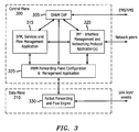
- FIG. 3 illustrates data flow in a control plane and a data plane including various CAPs according to example embodiments
- FIG. 4 is an application message flow diagram for according to example embodiments.
- FIG. 5 illustrates various examples of audit flows according to example embodiments
- FIG. 6 shows example embodiments of Type I to III audits.
- spatially relative terms e.g., “beneath,” “below,” “lower,” “above,” “upper” and the like, may be used herein for ease of description to describe one element or a relationship between a feature and another element or feature as illustrated in the figures. It will be understood that the spatially relative terms are intended to encompass different orientations of the device in use or operation in addition to the orientation depicted in the Figures. For example, if the device in the figures is turned over, elements described as “below” or “beneath” other elements or features would then be oriented “above” the other elements or features. Thus, for example, the term “below” can encompass both an orientation which is above as well as below. The device may be otherwise oriented (rotated 90 degrees or viewed or referenced at other orientations) and the spatially relative descriptors used herein should be interpreted accordingly.
- illustrative embodiments will be described with reference to acts and symbolic representations of operations (e.g., in the form of flowcharts) that may be implemented as program modules or functional processes include routines, programs, objects, components, data structures, etc., that perform particular tasks or implement particular abstract data types and may be implemented using existing hardware at existing network elements or control nodes (e.g., a scheduler located at a base station or Node B).
- Such existing hardware may include one or more Central Processing Units (CPUs), digital signal processors (DSPs), application-specific-integrated-circuits, field programmable gate arrays (FPGAs) computers or the like.
- CPUs Central Processing Units
- DSPs digital signal processors
- FPGAs field programmable gate arrays
- the software implemented aspects of the invention are typically encoded on some form of program storage medium or implemented over some type of transmission medium.
- the program storage medium may be magnetic (e.g., a floppy disk or a hard drive) or optical (e.g., a compact disk read only memory, or “CD ROM”), and may be read only or random access.
- the transmission medium may be twisted wire pairs, coaxial cable, optical fiber, or some other suitable transmission medium known to the art. The invention is not limited by these aspects of any given implementation.
- Example embodiments are directed to methods of Asynchronous Checkpointing with Audits (ACWA).
- the ACWA model operates under known embedded system assumptions, for example, that persistent application data is distributed across multiple cooperating application processes (CAPs), as discussed above, with each process “owning” a subset of the data.
- CAPs cooperating application processes
- Data synchronization for the state information related to the same object(s) managed across different CAPS is performed via custom Inter-Process Communication mechanisms.
- FIG. 2 illustrates an example flow for the ACWA model.
- at least one CAP processes application related events pertaining to at least one object at S 200 .
- the at least one CAP changes and/or modifies the application state data affected by the processed events.
- Each CAP independently manages a subset of state information (records) pertaining to the specified software application.
- the CAP independently determines if its subset of state data (both modified and not) has reached a “stable state” at step S 210 . If the subset of state data has not reached a stable state, then the CAP continues to wait to process more events returning to step S 200 .
- the determination of a “stable state” depends on the specific CAP and object corresponding to the state data at issue.
- the CAP will checkpoint the state data at different times and based on different levels of modification.
- Stable and transient states are generally application and object specific and depend upon the chosen state recovery scheme. Checkpointed stable states may be recovered during application fallback to last known stable state, while non-checkpointed transient states shall be lost on recovery.
- Checkpointing is a technique for inserting fault tolerance into computing systems by storing a snapshot of the current application state, and using the checkpointed data for restarting in case of failure.
- Checkpointing may include, e.g., checkpointing to local non-volatile memory storage and checkpointing to remote network storage (shown replication to Standby node storage S 225 )
- CAPs on a standby node restore the CAP object state data based upon previously checkpointed active node CAP object state data (replicated from active), and on demand audits of restored object state data across CAPs are enforced to verify the object state data consistency after failover.
- the standby node assumes functions of failed active node and for each CAP the dynamic object's state is restored from the replicated checkpointed object state data from the active node.
- cross-CAP audits are performed on new active node (former standby) to verify that the restored object state data (recovered from asynchronously checkpointed data by the former active CAPs) is consistent. These audits allow to recover from object state inconsistencies for those objects (with state distributed across multiple CAPS) which state transition occurred in a short period of time preceding the failover, leading to inconsistency in asynchronously checkpointed subsets of state data.
- Equipment failover may include, e.g., controlled failovers, uncontrolled failovers (e.g., Standby node detects Active node crash/power failure and takes over), maintenance procedures (e.g., software/firmware upgrades), and software restarts of the control plane without hardware redundancy.
- controlled failovers e.g., uncontrolled failovers (e.g., Standby node detects Active node crash/power failure and takes over), maintenance procedures (e.g., software/firmware upgrades), and software restarts of the control plane without hardware redundancy.
- uncontrolled failovers e.g., Standby node detects Active node crash/power failure and takes over
- maintenance procedures e.g., software/firmware upgrades
- software restarts of the control plane without hardware redundancy e.g., software/firmware upgrades
- FIG. 3 shows an example of the relationship between an OA&M CAP 305 , various types of CAPs 315 , 320 , 325 , and 330 , a control plane 300 , a data plane 310 , and other network elements (not shown).
- the hardware-based data plane 310 (including different network nodes, e.g., FPGAs, Network Processor) may implement a bearer traffic packet forwarding and flow engine 330 and perform asynchronous exchange of data plane configuration and link state related events with the Hardware Manager (HWM) CAP 325 in the control plane 300 .
- HWM Hardware Manager
- the OA&M CAP 305 implements a product and application specific OA&M interface to an Element/Network Management Station (EMS/NMS). Depending upon product-specific requirements, one of or a combination of SNMP, HTTP, CLI, XML based OA&M interfaces may be used.
- EMS/NMS Element/Network Management Station
- the HWM CAP 325 may implement a hardware abstraction layer, hiding hardware specifics and dependencies from the higher layer applications (e.g., hardware forwarding plane might be using a variety of network processors, multi-core processors, FPGAs, DSPs, ASICs, etc., while higher layer protocol software remains unchanged).
- the HWM CAP 325 receives asynchronous events from the OA&M CAP 305 , the services and flow management (SFM) CAP 315 and the interface manager and networking protocol (IFM) CAP 320 to configure the data plane, based upon user configuration and networking protocol specific logic.
- SFM services and flow management
- IDM interface manager and networking protocol
- a user may configure a VLAN logical interface (LIF) via the OA&M CAP 305 as administratively up (e.g., forwarding traffic).
- LIF VLAN logical interface
- the IFM CAP 320 might request to bring the LIF down (e.g., not forwarding traffic).
- the Spanning Tree protocol as defined in IEEE 802.1D, eliminates user plane loops in the network that would be looped indefinitely instead of being forwarded to a destination.
- a user plane is a forwarding mechanism for end user traffic. It is typically separate from the control plane, which is a set of protocols defined to establish the user plane. Once the user plane is established, end user data traffic is forwarded.
- the HWM CAP 325 might report the link for the LIF to be down as well.
- Another example is a routing application in which a user configures an IP interface to be up via the OA&M CAP 305 .
- the IFM CAP 320 then configures new flows after learning routing information from a network peer via Open Shortest Path First (OSPF).
- OSPF is one of IP routing link-state protocols as defined in the IETF standards.
- the IFM CAP (or several CAPs) 320 implements product-specific networking protocol functionality and manages interface tables and interface stacking relationships.
- networking equipment manages interface tables defined by corresponding IETF standards for types of physical and logical interfaces a device contains.
- An interface protocol stack may define the stacking relationship between physical and logical interfaces.
- CAPS may implement product-specific networking protocol functionality.
- the IFM CAP 320 also exchanges asynchronous events with networking protocol peers to learn/advertise protocol specific information.
- Networking protocols e.g., routing protocols, Bridging, MPLS, Mobile IP, AAA
- the IFM CAP 320 also receives asynchronous events from the OA&M CAP 305 and exchanges asynchronous events with the SFM CAP 315 and the HWM CAP 325 .
- the SFM CAP 315 realizes and manages product-specific services and flows.
- the SFM CAP 315 may be configured by a user via the OA&M APPLICATION 305 .
- the SFM CAP 315 also collects per service and flow accounting/charging statistics from HWM using product-specific IPC mechanisms.
- the HWM CAP 325 collects traffic statistics from forwarding plane and reports to the SFM CAP 315 .
- the SFM CAP 315 also exchanges asynchronous events with the OA&M APPLICATION 305 , the IFM CAP 320 , and the HWM CAP 325 .
- An example of a logical interface object (LIF) associated with a bridging service may have information distributed across the SFM CAP 315 , IFM CAP 320 , and HWM CAP 325 .
- the SFM CAP 315 may include logical interface state information, for example, configuration (MIB—Management Information Base) data (e.g., ifname, associated physical interface (slot/port number), VLAN id, admin status, etc.) and dynamic persistent data.
- MIB Management Information Base
- the IFM CAP 320 may include dynamic persistent data (e.g., ifindex, shadowed admin status, oper status, ifname, iftype).
- the HWM CAP 325 may include, dynamic persistent data (e.g., related hardware data path configuration, ifindex, admin status (directly from the hardware drivers), oper status (directly from the hardware drivers), and link status of the underlying physical interface (directly from the hardware drivers)).
- the iftable is a collection of all interfaces and the ifindex is a way of referring to the interfaces.
- Admin status signifies a state of the interface administratively provisioned by the operator.
- Oper status signifies an actual state of the interface.
- the operator may configure admin status of an interface as UP (active), but oper status may be down because the physical link is down.
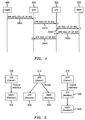
- FIG. 4 illustrates a sample message flow diagram for LIF creation.
- LIF creation command e.g., an IPC message
- the SFM CAP 315 creates a local object instance for the LIF, and initializes its local state machine.
- the SFM CAP 315 then forms an IPC request message and sends the message to the IFM CAP 320 in step S 410 .
- the IFM CAP 320 then creates a LIF in the admin down state and a new row in the iftable for the new LIF.
- the IFM CAP 320 also updates the iftable to reflect the LIF and physical interface relationship and assigns an ifindex for the new LIF.
- the IFM CAP 320 then appends the ifindex to the IPC message and forwards the IPC message to the HWM CAP 325 in step S 420 .
- the HWM CAP 325 creates a local LIF object instance and adds a new LIF to the list of LIFs associated with the given physical interface.
- the HWM CAP 325 then creates a LIF instance in the data plane in the admin down state using the corresponding interface to configure the actual User plane.
- the HWM CAP 325 sends a response back to the IFM CAP 320 , containing a new LIF ifindex, admin, and oper state, in step S 430 .
- the IFM CAP 320 Upon receipt of the response, the IFM CAP 320 updates the LIF admin and oper state in the iftable and ifstack table. The IFM CAP 320 then forwards the IPC response to the SFM CAP 315 . The SFM CAP 315 receives the response and updates the local state information for the LIF.
- the LIF admin status up/down flow procedures may be triggered e.g., by the OA&M CAP 305 or by Spanning Tree calculation by the IFM CAP 320 . Regardless of how the procedures are triggered, each CAP independently maintains internal stable states of the LIF. Once the LIF in a CAP reaches a stable state, the CAP independently checkpoints the relevant object state. For example, in FIG. 4 , the SFM CAP 315 may perform a checkpoint in steps S 400 and S 440 , HWM CAP 325 may perform a checkpoint in step S 420 , and IFM CAP 320 may perform a checkpoint in step S 430 .
- Audits as described below are used to ensure data consistency: across CAPs for application objects, between control and data planes and between CAP runtime data and stored/replicated checkpointed data. Audits are typically performed for bulk application objects and compare a relevant subset of application object state data between the various CAPs, nodes and/or memories to ensure consistency of distributed object state data. There are 4 recommended audit types, types I-III are shown in FIG. 6 . Type I audits must be used if two or more CAPs are involved and Type II, III, and IV increase reliability and decrease recovery time on failover.
- the first audit is a type I audit, which is used vertically across CAPs P1-Active, P2-Active to verify run-time data consistency of subsets of the object state data managed by different CAPs.
- the same audit may be used for run-time active applications on initialization of a standby module after failover (see FIG. 2 ).
- the audit may be initiated in bulk (periodically in the background and on demand) by the owner CAP towards other member CAPs.
- type I audits may be background audits across CAPS that are performed following the “natural” application and product specific IPC flow, based upon the object-related parent-child hierarchy established during registration with the automation framework.
- the second audit is a type II audit, which is used between run-time application data and locally checkpointed “packed” configuration and dynamic persistent data records for the same object in the context of each CAP.
- audit type II may be used.
- the third audit is a type III audit, which is used between locally checkpointed per CAP data and replicated (e.g., 1+1 or N+1 redundancy) data for the same HA object identifier.
- the HA object identifier identifies the CAP owner and object.
- the fourth audit is a type IV audit, which is used for orphaned records (e.g., records that were not scanned for a certain period of time by the type I audits) for the same object and CAP.
- orphaned records e.g., records that were not scanned for a certain period of time by the type I audits
- Automated consistency audits across CAPs for a particular object type follow the registered application hierarchy as shown in FIG. 5 .
Abstract
Description
Claims (13)
Priority Applications (1)
| Application Number | Priority Date | Filing Date | Title |
|---|---|---|---|
| US12/318,850 US8041994B2 (en) | 2009-01-09 | 2009-01-09 | Asynchronous checkpointing with audits in high availability networks |
Applications Claiming Priority (1)
| Application Number | Priority Date | Filing Date | Title |
|---|---|---|---|
| US12/318,850 US8041994B2 (en) | 2009-01-09 | 2009-01-09 | Asynchronous checkpointing with audits in high availability networks |
Publications (2)
| Publication Number | Publication Date |
|---|---|
| US20100180106A1 US20100180106A1 (en) | 2010-07-15 |
| US8041994B2 true US8041994B2 (en) | 2011-10-18 |
Family
ID=42319852
Family Applications (1)
| Application Number | Title | Priority Date | Filing Date |
|---|---|---|---|
| US12/318,850 Expired - Fee Related US8041994B2 (en) | 2009-01-09 | 2009-01-09 | Asynchronous checkpointing with audits in high availability networks |
Country Status (1)
| Country | Link |
|---|---|
| US (1) | US8041994B2 (en) |
Cited By (4)
| Publication number | Priority date | Publication date | Assignee | Title |
|---|---|---|---|---|
| US20100185682A1 (en) * | 2009-01-09 | 2010-07-22 | Lucent Technologies Inc. | Object identifier and common registry to support asynchronous checkpointing with audits |
| US9032199B1 (en) | 2012-12-28 | 2015-05-12 | Google Inc. | Systems, devices, and methods for capturing information, creating loadable images, and providing for restarts in a computer system |
| US9652336B2 (en) | 2015-03-13 | 2017-05-16 | International Business Machines Corporation | Resilient programming frameworks for handling failures in parallel programs |
| US10949305B2 (en) * | 2017-12-19 | 2021-03-16 | SK Hynix Inc. | Memory system and operating method thereof |
Families Citing this family (3)
| Publication number | Priority date | Publication date | Assignee | Title |
|---|---|---|---|---|
| US8375389B2 (en) | 2010-10-20 | 2013-02-12 | Microsoft Corporation | Ordered scheduling of suspended processes based on resumption events |
| US9128902B2 (en) * | 2013-04-25 | 2015-09-08 | Netapp, Inc. | Systems and methods for managing disaster recovery in a storage system |
| CN112823492A (en) * | 2018-10-08 | 2021-05-18 | 西安姆贝拉有限公司 | System, apparatus and method for providing an end-to-end solution for a network |
Citations (13)
| Publication number | Priority date | Publication date | Assignee | Title |
|---|---|---|---|---|
| US6026499A (en) * | 1997-01-31 | 2000-02-15 | Kabushiki Kaisha Toshiba | Scheme for restarting processes at distributed checkpoints in client-server computer system |
| US6175876B1 (en) * | 1998-07-09 | 2001-01-16 | International Business Machines Corporation | Mechanism for routing asynchronous state changes in a 3-tier application |
| US20030023898A1 (en) * | 2001-07-16 | 2003-01-30 | Jacobs Dean Bernard | Layered architecture for data replication |
| US20030046342A1 (en) * | 2001-07-17 | 2003-03-06 | Felt Edward P. | System and method for transaction processing with delegated commit feature |
| US6823474B2 (en) * | 2000-05-02 | 2004-11-23 | Sun Microsystems, Inc. | Method and system for providing cluster replicated checkpoint services |
| US20050015663A1 (en) * | 2003-06-25 | 2005-01-20 | Philippe Armangau | Data recovery with internet protocol replication with or without full resync |
| US6877111B2 (en) * | 2001-03-26 | 2005-04-05 | Sun Microsystems, Inc. | Method and apparatus for managing replicated and migration capable session state for a Java platform |
| US20050160315A1 (en) * | 2004-01-15 | 2005-07-21 | Oracle International Corporation | Geographically distributed clusters |
| US20060168473A1 (en) * | 2005-01-25 | 2006-07-27 | International Business Machines Corporation | Method and system for deciding when to checkpoint an application based on risk analysis |
| US20070277056A1 (en) * | 2003-11-17 | 2007-11-29 | Virginia Tech Intellectual Properties, Inc. | Transparent checkpointing and process migration in a distributed system |
| US7657578B1 (en) * | 2004-12-20 | 2010-02-02 | Symantec Operating Corporation | System and method for volume replication in a storage environment employing distributed block virtualization |
| US7743381B1 (en) * | 2003-09-16 | 2010-06-22 | Symantec Operating Corporation | Checkpoint service |
| US7779298B2 (en) * | 2007-06-11 | 2010-08-17 | International Business Machines Corporation | Distributed job manager recovery |
-
2009
- 2009-01-09 US US12/318,850 patent/US8041994B2/en not_active Expired - Fee Related
Patent Citations (14)
| Publication number | Priority date | Publication date | Assignee | Title |
|---|---|---|---|---|
| US6026499A (en) * | 1997-01-31 | 2000-02-15 | Kabushiki Kaisha Toshiba | Scheme for restarting processes at distributed checkpoints in client-server computer system |
| US6175876B1 (en) * | 1998-07-09 | 2001-01-16 | International Business Machines Corporation | Mechanism for routing asynchronous state changes in a 3-tier application |
| US6823474B2 (en) * | 2000-05-02 | 2004-11-23 | Sun Microsystems, Inc. | Method and system for providing cluster replicated checkpoint services |
| US6877111B2 (en) * | 2001-03-26 | 2005-04-05 | Sun Microsystems, Inc. | Method and apparatus for managing replicated and migration capable session state for a Java platform |
| US20030023898A1 (en) * | 2001-07-16 | 2003-01-30 | Jacobs Dean Bernard | Layered architecture for data replication |
| US20030046342A1 (en) * | 2001-07-17 | 2003-03-06 | Felt Edward P. | System and method for transaction processing with delegated commit feature |
| US20050015663A1 (en) * | 2003-06-25 | 2005-01-20 | Philippe Armangau | Data recovery with internet protocol replication with or without full resync |
| US7743381B1 (en) * | 2003-09-16 | 2010-06-22 | Symantec Operating Corporation | Checkpoint service |
| US20070277056A1 (en) * | 2003-11-17 | 2007-11-29 | Virginia Tech Intellectual Properties, Inc. | Transparent checkpointing and process migration in a distributed system |
| US20090327807A1 (en) * | 2003-11-17 | 2009-12-31 | Virginia Tech Intellectual Properties, Inc. | Transparent checkpointing and process migration in a distributed system |
| US20050160315A1 (en) * | 2004-01-15 | 2005-07-21 | Oracle International Corporation | Geographically distributed clusters |
| US7657578B1 (en) * | 2004-12-20 | 2010-02-02 | Symantec Operating Corporation | System and method for volume replication in a storage environment employing distributed block virtualization |
| US20060168473A1 (en) * | 2005-01-25 | 2006-07-27 | International Business Machines Corporation | Method and system for deciding when to checkpoint an application based on risk analysis |
| US7779298B2 (en) * | 2007-06-11 | 2010-08-17 | International Business Machines Corporation | Distributed job manager recovery |
Non-Patent Citations (1)
| Title |
|---|
| "Media Access Control (MAC) Bridges." 802.1D IEEE Standard for Local and Metropolitan Area Networks. IEEE Computer Society. Jun. 9, 2004. |
Cited By (9)
| Publication number | Priority date | Publication date | Assignee | Title |
|---|---|---|---|---|
| US20100185682A1 (en) * | 2009-01-09 | 2010-07-22 | Lucent Technologies Inc. | Object identifier and common registry to support asynchronous checkpointing with audits |
| US9032199B1 (en) | 2012-12-28 | 2015-05-12 | Google Inc. | Systems, devices, and methods for capturing information, creating loadable images, and providing for restarts in a computer system |
| US9652336B2 (en) | 2015-03-13 | 2017-05-16 | International Business Machines Corporation | Resilient programming frameworks for handling failures in parallel programs |
| US9652337B2 (en) | 2015-03-13 | 2017-05-16 | International Business Machines Corporation | Resilient programming frameworks for handling failures in parallel programs |
| US10275323B2 (en) | 2015-03-13 | 2019-04-30 | International Business Machines Corporation | Resilient programming frameworks for handling failures in parallel programs |
| US10296424B2 (en) | 2015-03-13 | 2019-05-21 | International Business Machines Corporation | Resilient programming frameworks for handling failures in parallel programs |
| US10831616B2 (en) | 2015-03-13 | 2020-11-10 | International Business Machines Corporation | Resilient programming frameworks for iterative computations |
| US10831617B2 (en) | 2015-03-13 | 2020-11-10 | International Business Machines Corporation | Resilient programming frameworks for iterative computations on computer systems |
| US10949305B2 (en) * | 2017-12-19 | 2021-03-16 | SK Hynix Inc. | Memory system and operating method thereof |
Also Published As
| Publication number | Publication date |
|---|---|
| US20100180106A1 (en) | 2010-07-15 |
Similar Documents
| Publication | Publication Date | Title |
|---|---|---|
| US8041994B2 (en) | Asynchronous checkpointing with audits in high availability networks | |
| Ferguson et al. | Orion: Google's {Software-Defined} Networking Control Plane | |
| US7587633B2 (en) | Fault tolerant routing in a network routing system based on a passive replication approach | |
| EP3895388B1 (en) | Server redundant network paths | |
| US9455898B2 (en) | System and method for facilitating protection against run-away subnet manager instances in a middleware machine environment | |
| US7539744B2 (en) | Network operating system for maintaining redundant master control blade management information | |
| US6332198B1 (en) | Network device for supporting multiple redundancy schemes | |
| US9021459B1 (en) | High availability in-service software upgrade using virtual machine instances in dual control units of a network device | |
| JP2005535241A (en) | Method of moving application software in multicomputer architecture, multicomputer method and apparatus for realizing continuity of operation using the moving method | |
| KR20150048835A (en) | System and method for supporting discovery and routing degraded fat-trees in a middleware machine environment | |
| Nguyen et al. | A software-defined networking approach for disaster-resilient WANs | |
| US20120036169A1 (en) | Object identifier and common registry to support asynchronous checkpointing with audits | |
| WO2012171380A1 (en) | Far-end failure processing method and device for ethernet | |
| CN112087375A (en) | WAN port switching method of WAN port standby router, storage medium and router | |
| WO2012100571A1 (en) | Centralized management method and system for multiple tunnels with the same path | |
| EP1782202A2 (en) | Computing system redundancy and fault tolerance | |
| US20120284274A1 (en) | Method and device for service management | |
| CN112187523A (en) | Network high-availability implementation method and super-convergence system | |
| Vilchez et al. | Fault tolerance comparison of onos and opendaylight sdn controllers | |
| Cisco | 2.1.00 Version Software Release Notes for Cisco WAN MGX 8850 Software | |
| Akanbi et al. | Fast fail-over technique for distributed controller architecture in software-defined networks | |
| US9104562B2 (en) | Enabling communication over cross-coupled links between independently managed compute and storage networks | |
| CN116248581A (en) | Cloud scene gateway cluster master-slave switching method and system based on SDN | |
| CN117354267A (en) | Link failure processing method, device, equipment, storage medium and program product | |
| CN117411840A (en) | Link failure processing method, device, equipment, storage medium and program product |
Legal Events
| Date | Code | Title | Description |
|---|---|---|---|
| AS | Assignment |
Owner name: ALCATEL-LUCENT, NEW JERSEY Free format text: ASSIGNMENT OF ASSIGNORS INTEREST;ASSIGNORS:GRINSHPUN, ED;SHARMA, SAMEER;WILFORD, PAUL;SIGNING DATES FROM 20081113 TO 20081114;REEL/FRAME:022146/0519 |
|
| FEPP | Fee payment procedure |
Free format text: PAYOR NUMBER ASSIGNED (ORIGINAL EVENT CODE: ASPN); ENTITY STATUS OF PATENT OWNER: LARGE ENTITY |
|
| ZAAA | Notice of allowance and fees due |
Free format text: ORIGINAL CODE: NOA |
|
| ZAAB | Notice of allowance mailed |
Free format text: ORIGINAL CODE: MN/=. |
|
| STCF | Information on status: patent grant |
Free format text: PATENTED CASE |
|
| FPAY | Fee payment |
Year of fee payment: 4 |
|
| AS | Assignment |
Owner name: PROVENANCE ASSET GROUP LLC, CONNECTICUT Free format text: ASSIGNMENT OF ASSIGNORS INTEREST;ASSIGNORS:NOKIA TECHNOLOGIES OY;NOKIA SOLUTIONS AND NETWORKS BV;ALCATEL LUCENT SAS;REEL/FRAME:043877/0001 Effective date: 20170912 Owner name: NOKIA USA INC., CALIFORNIA Free format text: SECURITY INTEREST;ASSIGNORS:PROVENANCE ASSET GROUP HOLDINGS, LLC;PROVENANCE ASSET GROUP LLC;REEL/FRAME:043879/0001 Effective date: 20170913 Owner name: CORTLAND CAPITAL MARKET SERVICES, LLC, ILLINOIS Free format text: SECURITY INTEREST;ASSIGNORS:PROVENANCE ASSET GROUP HOLDINGS, LLC;PROVENANCE ASSET GROUP, LLC;REEL/FRAME:043967/0001 Effective date: 20170913 |
|
| AS | Assignment |
Owner name: NOKIA US HOLDINGS INC., NEW JERSEY Free format text: ASSIGNMENT AND ASSUMPTION AGREEMENT;ASSIGNOR:NOKIA USA INC.;REEL/FRAME:048370/0682 Effective date: 20181220 |
|
| FEPP | Fee payment procedure |
Free format text: MAINTENANCE FEE REMINDER MAILED (ORIGINAL EVENT CODE: REM.); ENTITY STATUS OF PATENT OWNER: LARGE ENTITY |
|
| FEPP | Fee payment procedure |
Free format text: 7.5 YR SURCHARGE - LATE PMT W/IN 6 MO, LARGE ENTITY (ORIGINAL EVENT CODE: M1555); ENTITY STATUS OF PATENT OWNER: LARGE ENTITY |
|
| MAFP | Maintenance fee payment |
Free format text: PAYMENT OF MAINTENANCE FEE, 8TH YEAR, LARGE ENTITY (ORIGINAL EVENT CODE: M1552); ENTITY STATUS OF PATENT OWNER: LARGE ENTITY Year of fee payment: 8 |
|
| AS | Assignment |
Owner name: PROVENANCE ASSET GROUP LLC, CONNECTICUT Free format text: RELEASE BY SECURED PARTY;ASSIGNOR:CORTLAND CAPITAL MARKETS SERVICES LLC;REEL/FRAME:058983/0104 Effective date: 20211101 Owner name: PROVENANCE ASSET GROUP HOLDINGS LLC, CONNECTICUT Free format text: RELEASE BY SECURED PARTY;ASSIGNOR:CORTLAND CAPITAL MARKETS SERVICES LLC;REEL/FRAME:058983/0104 Effective date: 20211101 Owner name: PROVENANCE ASSET GROUP LLC, CONNECTICUT Free format text: RELEASE BY SECURED PARTY;ASSIGNOR:NOKIA US HOLDINGS INC.;REEL/FRAME:058363/0723 Effective date: 20211129 Owner name: PROVENANCE ASSET GROUP HOLDINGS LLC, CONNECTICUT Free format text: RELEASE BY SECURED PARTY;ASSIGNOR:NOKIA US HOLDINGS INC.;REEL/FRAME:058363/0723 Effective date: 20211129 |
|
| AS | Assignment |
Owner name: RPX CORPORATION, CALIFORNIA Free format text: ASSIGNMENT OF ASSIGNORS INTEREST;ASSIGNOR:PROVENANCE ASSET GROUP LLC;REEL/FRAME:059352/0001 Effective date: 20211129 |
|
| AS | Assignment |
Owner name: BARINGS FINANCE LLC, AS COLLATERAL AGENT, NORTH CAROLINA Free format text: PATENT SECURITY AGREEMENT;ASSIGNOR:RPX CORPORATION;REEL/FRAME:063429/0001 Effective date: 20220107 |
|
| FEPP | Fee payment procedure |
Free format text: MAINTENANCE FEE REMINDER MAILED (ORIGINAL EVENT CODE: REM.); ENTITY STATUS OF PATENT OWNER: LARGE ENTITY |
|
| LAPS | Lapse for failure to pay maintenance fees |
Free format text: PATENT EXPIRED FOR FAILURE TO PAY MAINTENANCE FEES (ORIGINAL EVENT CODE: EXP.); ENTITY STATUS OF PATENT OWNER: LARGE ENTITY |
|
| STCH | Information on status: patent discontinuation |
Free format text: PATENT EXPIRED DUE TO NONPAYMENT OF MAINTENANCE FEES UNDER 37 CFR 1.362 |
|
| FP | Lapsed due to failure to pay maintenance fee |
Effective date: 20231018 |