US8042713B2 - Aerosol systems and methods for dispensing texture material - Google Patents
Aerosol systems and methods for dispensing texture material Download PDFInfo
- Publication number
- US8042713B2 US8042713B2 US12/859,195 US85919510A US8042713B2 US 8042713 B2 US8042713 B2 US 8042713B2 US 85919510 A US85919510 A US 85919510A US 8042713 B2 US8042713 B2 US 8042713B2
- Authority
- US
- United States
- Prior art keywords
- valve
- aerosol
- stem
- texture
- texture material
- Prior art date
- Legal status (The legal status is an assumption and is not a legal conclusion. Google has not performed a legal analysis and makes no representation as to the accuracy of the status listed.)
- Expired - Fee Related
Links
- 239000000463 material Substances 0.000 title claims abstract description 201
- 239000000443 aerosol Substances 0.000 title claims abstract description 47
- 238000000034 method Methods 0.000 title description 7
- 239000003380 propellant Substances 0.000 claims abstract description 60
- 239000000758 substrate Substances 0.000 claims abstract description 22
- 239000006260 foam Substances 0.000 claims abstract description 10
- 229920000877 Melamine resin Polymers 0.000 claims abstract description 9
- JDSHMPZPIAZGSV-UHFFFAOYSA-N melamine Chemical compound NC1=NC(N)=NC(N)=N1 JDSHMPZPIAZGSV-UHFFFAOYSA-N 0.000 claims abstract description 9
- JOYRKODLDBILNP-UHFFFAOYSA-N Ethyl urethane Chemical compound CCOC(N)=O JOYRKODLDBILNP-UHFFFAOYSA-N 0.000 claims abstract description 6
- 239000012530 fluid Substances 0.000 claims description 20
- 229930195733 hydrocarbon Natural products 0.000 claims description 6
- 150000002430 hydrocarbons Chemical class 0.000 claims description 6
- 239000004215 Carbon black (E152) Substances 0.000 claims description 5
- 239000007921 spray Substances 0.000 description 13
- 239000011236 particulate material Substances 0.000 description 12
- 239000011248 coating agent Substances 0.000 description 11
- 238000000576 coating method Methods 0.000 description 11
- 239000012071 phase Substances 0.000 description 11
- IJGRMHOSHXDMSA-UHFFFAOYSA-N Atomic nitrogen Chemical compound N#N IJGRMHOSHXDMSA-UHFFFAOYSA-N 0.000 description 10
- 239000004793 Polystyrene Substances 0.000 description 8
- 229920002223 polystyrene Polymers 0.000 description 8
- 238000010276 construction Methods 0.000 description 7
- 230000000712 assembly Effects 0.000 description 6
- 238000000429 assembly Methods 0.000 description 6
- 239000011261 inert gas Substances 0.000 description 5
- 239000007788 liquid Substances 0.000 description 5
- 239000007791 liquid phase Substances 0.000 description 5
- 229910052757 nitrogen Inorganic materials 0.000 description 5
- ATUOYWHBWRKTHZ-UHFFFAOYSA-N Propane Chemical compound CCC ATUOYWHBWRKTHZ-UHFFFAOYSA-N 0.000 description 4
- 238000013459 approach Methods 0.000 description 4
- 230000000881 depressing effect Effects 0.000 description 4
- 239000006261 foam material Substances 0.000 description 4
- 239000000203 mixture Substances 0.000 description 4
- 239000002245 particle Substances 0.000 description 4
- DNIAPMSPPWPWGF-UHFFFAOYSA-N Propylene glycol Chemical compound CC(O)CO DNIAPMSPPWPWGF-UHFFFAOYSA-N 0.000 description 3
- 230000008901 benefit Effects 0.000 description 3
- 230000000994 depressogenic effect Effects 0.000 description 3
- 239000007789 gas Substances 0.000 description 3
- 230000001788 irregular Effects 0.000 description 3
- VTYYLEPIZMXCLO-UHFFFAOYSA-L Calcium carbonate Chemical compound [Ca+2].[O-]C([O-])=O VTYYLEPIZMXCLO-UHFFFAOYSA-L 0.000 description 2
- 239000000853 adhesive Substances 0.000 description 2
- 230000001070 adhesive effect Effects 0.000 description 2
- 239000011230 binding agent Substances 0.000 description 2
- IAQRGUVFOMOMEM-UHFFFAOYSA-N but-2-ene Chemical group CC=CC IAQRGUVFOMOMEM-UHFFFAOYSA-N 0.000 description 2
- 239000001273 butane Substances 0.000 description 2
- 238000004891 communication Methods 0.000 description 2
- 238000000151 deposition Methods 0.000 description 2
- 238000006073 displacement reaction Methods 0.000 description 2
- 239000000945 filler Substances 0.000 description 2
- 239000007792 gaseous phase Substances 0.000 description 2
- 229910052751 metal Inorganic materials 0.000 description 2
- 239000002184 metal Substances 0.000 description 2
- IJDNQMDRQITEOD-UHFFFAOYSA-N n-butane Chemical compound CCCC IJDNQMDRQITEOD-UHFFFAOYSA-N 0.000 description 2
- OFBQJSOFQDEBGM-UHFFFAOYSA-N n-pentane Natural products CCCCC OFBQJSOFQDEBGM-UHFFFAOYSA-N 0.000 description 2
- 229920000058 polyacrylate Polymers 0.000 description 2
- -1 polypropylene Polymers 0.000 description 2
- 229920006327 polystyrene foam Polymers 0.000 description 2
- 239000001294 propane Substances 0.000 description 2
- 239000004576 sand Substances 0.000 description 2
- 238000005507 spraying Methods 0.000 description 2
- 229920002994 synthetic fiber Polymers 0.000 description 2
- XLYOFNOQVPJJNP-UHFFFAOYSA-N water Substances O XLYOFNOQVPJJNP-UHFFFAOYSA-N 0.000 description 2
- 108010053481 Antifreeze Proteins Proteins 0.000 description 1
- 235000008733 Citrus aurantifolia Nutrition 0.000 description 1
- LFQSCWFLJHTTHZ-UHFFFAOYSA-N Ethanol Chemical compound CCO LFQSCWFLJHTTHZ-UHFFFAOYSA-N 0.000 description 1
- 239000004698 Polyethylene Substances 0.000 description 1
- 239000004743 Polypropylene Substances 0.000 description 1
- 239000011398 Portland cement Substances 0.000 description 1
- 235000011941 Tilia x europaea Nutrition 0.000 description 1
- 235000002017 Zea mays subsp mays Nutrition 0.000 description 1
- 241000482268 Zea mays subsp. mays Species 0.000 description 1
- 239000004479 aerosol dispenser Substances 0.000 description 1
- 230000002528 anti-freeze Effects 0.000 description 1
- 230000003115 biocidal effect Effects 0.000 description 1
- 239000003139 biocide Substances 0.000 description 1
- 230000009141 biological interaction Effects 0.000 description 1
- 229910000019 calcium carbonate Inorganic materials 0.000 description 1
- 239000004568 cement Substances 0.000 description 1
- 239000003995 emulsifying agent Substances 0.000 description 1
- 239000003063 flame retardant Substances 0.000 description 1
- 230000009969 flowable effect Effects 0.000 description 1
- 235000013305 food Nutrition 0.000 description 1
- 238000009472 formulation Methods 0.000 description 1
- 230000000855 fungicidal effect Effects 0.000 description 1
- 239000000417 fungicide Substances 0.000 description 1
- 239000004571 lime Substances 0.000 description 1
- 239000011344 liquid material Substances 0.000 description 1
- 238000004519 manufacturing process Methods 0.000 description 1
- 238000012986 modification Methods 0.000 description 1
- 230000004048 modification Effects 0.000 description 1
- 238000010422 painting Methods 0.000 description 1
- 239000010451 perlite Substances 0.000 description 1
- 235000019362 perlite Nutrition 0.000 description 1
- 239000011505 plaster Substances 0.000 description 1
- 239000004033 plastic Substances 0.000 description 1
- 229920003023 plastic Polymers 0.000 description 1
- 229920000573 polyethylene Polymers 0.000 description 1
- 229920001155 polypropylene Polymers 0.000 description 1
- 239000011253 protective coating Substances 0.000 description 1
- 230000000717 retained effect Effects 0.000 description 1
- 239000007787 solid Substances 0.000 description 1
- 239000000126 substance Substances 0.000 description 1
- 239000010455 vermiculite Substances 0.000 description 1
- 235000019354 vermiculite Nutrition 0.000 description 1
- 229910052902 vermiculite Inorganic materials 0.000 description 1
Images


Classifications
-
- E—FIXED CONSTRUCTIONS
- E04—BUILDING
- E04B—GENERAL BUILDING CONSTRUCTIONS; WALLS, e.g. PARTITIONS; ROOFS; FLOORS; CEILINGS; INSULATION OR OTHER PROTECTION OF BUILDINGS
- E04B1/00—Constructions in general; Structures which are not restricted either to walls, e.g. partitions, or floors or ceilings or roofs
- E04B1/62—Insulation or other protection; Elements or use of specified material therefor
- E04B1/74—Heat, sound or noise insulation, absorption, or reflection; Other building methods affording favourable thermal or acoustical conditions, e.g. accumulating of heat within walls
- E04B1/82—Heat, sound or noise insulation, absorption, or reflection; Other building methods affording favourable thermal or acoustical conditions, e.g. accumulating of heat within walls specifically with respect to sound only
- E04B1/84—Sound-absorbing elements
-
- B—PERFORMING OPERATIONS; TRANSPORTING
- B65—CONVEYING; PACKING; STORING; HANDLING THIN OR FILAMENTARY MATERIAL
- B65D—CONTAINERS FOR STORAGE OR TRANSPORT OF ARTICLES OR MATERIALS, e.g. BAGS, BARRELS, BOTTLES, BOXES, CANS, CARTONS, CRATES, DRUMS, JARS, TANKS, HOPPERS, FORWARDING CONTAINERS; ACCESSORIES, CLOSURES, OR FITTINGS THEREFOR; PACKAGING ELEMENTS; PACKAGES
- B65D83/00—Containers or packages with special means for dispensing contents
- B65D83/14—Containers or packages with special means for dispensing contents for delivery of liquid or semi-liquid contents by internal gaseous pressure, i.e. aerosol containers comprising propellant for a product delivered by a propellant
- B65D83/28—Nozzles, nozzle fittings or accessories specially adapted therefor
- B65D83/30—Nozzles, nozzle fittings or accessories specially adapted therefor for guiding the flow of spray, e.g. funnels, hoods
- B65D83/306—Actuators formed as a rigid elongate spout
-
- B—PERFORMING OPERATIONS; TRANSPORTING
- B65—CONVEYING; PACKING; STORING; HANDLING THIN OR FILAMENTARY MATERIAL
- B65D—CONTAINERS FOR STORAGE OR TRANSPORT OF ARTICLES OR MATERIALS, e.g. BAGS, BARRELS, BOTTLES, BOXES, CANS, CARTONS, CRATES, DRUMS, JARS, TANKS, HOPPERS, FORWARDING CONTAINERS; ACCESSORIES, CLOSURES, OR FITTINGS THEREFOR; PACKAGING ELEMENTS; PACKAGES
- B65D83/00—Containers or packages with special means for dispensing contents
- B65D83/14—Containers or packages with special means for dispensing contents for delivery of liquid or semi-liquid contents by internal gaseous pressure, i.e. aerosol containers comprising propellant for a product delivered by a propellant
- B65D83/44—Valves specially adapted therefor; Regulating devices
- B65D83/48—Lift valves, e.g. operated by push action
-
- B—PERFORMING OPERATIONS; TRANSPORTING
- B65—CONVEYING; PACKING; STORING; HANDLING THIN OR FILAMENTARY MATERIAL
- B65D—CONTAINERS FOR STORAGE OR TRANSPORT OF ARTICLES OR MATERIALS, e.g. BAGS, BARRELS, BOTTLES, BOXES, CANS, CARTONS, CRATES, DRUMS, JARS, TANKS, HOPPERS, FORWARDING CONTAINERS; ACCESSORIES, CLOSURES, OR FITTINGS THEREFOR; PACKAGING ELEMENTS; PACKAGES
- B65D83/00—Containers or packages with special means for dispensing contents
- B65D83/14—Containers or packages with special means for dispensing contents for delivery of liquid or semi-liquid contents by internal gaseous pressure, i.e. aerosol containers comprising propellant for a product delivered by a propellant
- B65D83/68—Dispensing two or more contents, e.g. sequential dispensing or simultaneous dispensing of two or more products without mixing them
-
- B—PERFORMING OPERATIONS; TRANSPORTING
- B65—CONVEYING; PACKING; STORING; HANDLING THIN OR FILAMENTARY MATERIAL
- B65D—CONTAINERS FOR STORAGE OR TRANSPORT OF ARTICLES OR MATERIALS, e.g. BAGS, BARRELS, BOTTLES, BOXES, CANS, CARTONS, CRATES, DRUMS, JARS, TANKS, HOPPERS, FORWARDING CONTAINERS; ACCESSORIES, CLOSURES, OR FITTINGS THEREFOR; PACKAGING ELEMENTS; PACKAGES
- B65D83/00—Containers or packages with special means for dispensing contents
- B65D83/14—Containers or packages with special means for dispensing contents for delivery of liquid or semi-liquid contents by internal gaseous pressure, i.e. aerosol containers comprising propellant for a product delivered by a propellant
- B65D83/75—Aerosol containers not provided for in groups B65D83/16 - B65D83/74
- B65D83/752—Aerosol containers not provided for in groups B65D83/16 - B65D83/74 characterised by the use of specific products or propellants
-
- E—FIXED CONSTRUCTIONS
- E04—BUILDING
- E04F—FINISHING WORK ON BUILDINGS, e.g. STAIRS, FLOORS
- E04F13/00—Coverings or linings, e.g. for walls or ceilings
- E04F13/02—Coverings or linings, e.g. for walls or ceilings of plastic materials hardening after applying, e.g. plaster
-
- E—FIXED CONSTRUCTIONS
- E04—BUILDING
- E04F—FINISHING WORK ON BUILDINGS, e.g. STAIRS, FLOORS
- E04F21/00—Implements for finishing work on buildings
- E04F21/02—Implements for finishing work on buildings for applying plasticised masses to surfaces, e.g. plastering walls
- E04F21/06—Implements for applying plaster, insulating material, or the like
- E04F21/08—Mechanical implements
- E04F21/12—Mechanical implements acting by gas pressure, e.g. steam pressure
Definitions
- the present invention relates to the art of repairing a textured surface and, more particularly, to dispensing systems and methods for depositing texture materials, such as acoustic texture material and stucco material, onto a portion of a textured surface to be repaired.
- texture materials such as acoustic texture material and stucco material
- a separate texture layer is applied to an interior or external surface, often prior to painting.
- the texture layer is typically formed by spraying texture material onto the surface.
- Texture material is a coating material that, when sprayed, does not form a smooth, thin coating. Instead, texture material is applied in or contains discrete drops, globs, or particles that dry to form a bumpy, irregular textured surface.
- Texture materials can be applied using any one of a number of application systems. During new construction, texture materials are commonly applied in a stream of compressed air using commercial hopper gun systems. For touch up or repair, texture material is commonly applied using hand operated pneumatic pumps or aerosol dispensing systems. Varying the parameters of the application system varies the size and spacing of the bumps to vary the look of the textured surface.
- acoustic texture material is commonly referred to as “acoustic” or “popcorn” texture material.
- acoustic texture material further comprises an aggregate material.
- the aggregate material is conventionally formed by polystyrene chips.
- chips made of polystyrene foam are dissolved by hydrocarbon aerosol propellant materials.
- aerosol dispensing systems for dispensing small amounts of acoustic texture material for repair or touch-up purposes use one of two approaches.
- the first approach is to mix a liquid hydrocarbon aerosol propellant material with chips made from materials other than polystyrene.
- chips made of materials other than polystyrene foam are used, the appearance and function of the texture surface may be different from that of the surrounding surface.
- the second approach is to combine polystyrene chips with a propellant material formed by a pressurized inert gas such as nitrogen or air.
- a pressurized inert gas such as nitrogen or air.
- This second approach allows the use of a conventional acoustic texture material including polystyrene chips.
- a pressurized inert gas causes the acoustic texture material to be dispensed very quickly.
- the use of pressurized inert gas as a propellant can make it difficult for a non-professional to control the application of the acoustic texture material.
- a second form of texture material is commonly referred to as “stucco.”
- stucco is a plaster material made of Portland cement, sand, to and lime. Conventional stucco is applied while soft to vertical walls or surfaces and then allowed to dry to form a decorative and protective coating. More recently, stucco surfaces have been formed using synthetic materials designed to resemble traditional stucco. Synthetic stucco is formed by acrylic polymers that, when dry, are flexible and water impervious. The term “stucco” will be used herein to refer both to traditional cement-based materials and to synthetic materials that resemble the traditional material.
- Stucco material can be damaged and should be repaired for both structural and aesthetic reasons.
- Non-professionals typically do not have the tools or materials to repair a damage stucco surface to match the look of the original stucco surface surrounding the patch.
- Various aerosol devices for spraying a coating material onto a wall surface, ceiling, or the like are known. Depending upon the composition of the coating material, and other factors, the coating material can be sprayed onto the surface in a variety of texture patterns.
- a somewhat roughened texture is achieved by utilizing a textured composition that forms into droplets when it is dispensed, with the material then hardening with these droplets providing the textured surface.
- solid particulate material is mixed with the liquid texture material so that with the particulate material being deposited with the hardenable liquid material on the wall surface, these particles provide the textured surface.
- the Assignee of the present invention has since approximately 1983 manufactured and sold manually operated devices for applying spray texture material onto walls and ceilings.
- These spray texture devices are described in one or more of the following U.S. Pat. Nos. 4,411,387; 4,955,545; 5,069,390; 5,188,295.
- These spray texture devices comprised a hopper containing hardenable material, a manually operated pump, and a nozzle. By pointing the device at the area being patched and operating the manual pump, the hardenable material and pressurized air generated by the pump were mixed in the nozzle and subsequently sprayed onto the area being patched.
- the present invention may be embodied as an aerosol texturing system for applying a layer of texture material on an uncoated portion of a substrate substantially to match a coated portion of the substrate.
- the aerosol texturing system comprises an aerosol assembly, texture material, and bi-phase propellant material.
- the texture material comprises a base portion and a particulate portion, where the particulate portion is made of at least one of urethane foam and melamine foam.
- the propellant material acts to on the texture material to force the texture material out of the aerosol assembly onto the uncoated portion of the substrate such that the layer of texture material on the uncoated portion of the substrate substantially matches the portion of the substrate coated with stucco material.
- FIG. 1 is a cut-away, side elevation view of a first example mechanical system of the present invention
- FIG. 2 is a cut-away, side elevation view of a second example mechanical system of the present invention
- FIGS. 3 and 4 are side elevation partial cut-away views depicting a method of use of the example dispensing systems of the present invention
- FIGS. 5 and 6 are front plan views depicting a portion of a wall structure under repair using the example dispensing systems of the present invention.
- FIG. 7 is a section view of a first embodiment of an aerosol dispensing system containing acoustic texture material incorporating particulate material of the present invention
- FIG. 8 is a section view of a second embodiment of an aerosol dispensing system containing acoustic texture material incorporating particulate material of the present invention
- FIG. 9 is an elevation view depicting the use of one or both of the first and second aerosol dispensing systems of FIGS. 7 and 8 being used to deposit acoustic texture material to a surface;
- FIG. 10 is a section view of the acoustic texture material after it has been deposited on the surface.
- FIGS. 11 and 12 are bottom plan views of the surface before and after the acoustic texture material has been deposited thereon.
- FIGS. 1 and 2 of the drawing Depicted in FIGS. 1 and 2 of the drawing are first and second examples of an aerosol stucco dispensing systems 20 a and 20 b constructed in accordance with, and embodying, the principles of the present invention.
- the appendices “a” and “b” will be used to refer to features unique to the first and second example texturing systems 20 a and 20 b , respectively.
- the example aerosol stucco dispensing systems 20 a and 20 b comprise a fluid system 22 and a mechanical system 24 a , 24 b .
- the fluid system 22 comprises a stucco material 30 to be dispensed and a propellant material 32 .
- the mechanical systems 24 a and 24 b comprise a container assembly 440 , an actuator 44 , and a valve assembly 42 a and 42 b , respectively.
- the stucco material 30 is shown only in the container assembly 440 ; as will be described in further detail below, the texture material will also forced into the valve assembly 42 a , 42 b and, in some situations, through and out the actuator 44 .
- the container assemblies 440 and actuator 44 of the example mechanical systems 24 a and 24 b are or may be the substantially the same and will be described only once below.
- the valve assemblies 42 a and 42 b differ and will each be described separately below.
- the stucco material 30 and propellant material 32 are stored within the container assembly 440 .
- the propellant material 32 pressurizes the stucco material 30 .
- the valve assembly 42 a , 42 b is normally in a closed state, and depressing the actuator 44 causes the valve assembly 42 a , 42 b to be placed into an open state.
- the pressurized propellant material 32 forces the stucco material 30 out of the container assembly 440 and onto a target surface to be coated.
- the example stucco material 30 comprises a coating portion 50 and a particulate portion 52 .
- the coating portion 50 exists in a liquid state when stored in the air-tight container assembly 440 but hardens when exposed to the air.
- the coating portion 50 is not per se important to any particular implementation of the present invention.
- the particulate portion 52 is formed by small chips or particles of irregular shape but relatively consistent volume.
- the example particulate portion 52 is formed by sand, perlite, vermiculite, polypropylene, polyethylene.
- the propellant material 32 must be compatible with the material or materials forming the particulate portion 52 of the stucco material 30 .
- the term “compatible” refers to the lack of chemical or biological interaction between the propellant material 32 and the particulate portion 52 that would substantially permanently alter the physical structure or appearance of the particulate portion 52 .
- composition of the propellant material 32 one or more of the following materials may be used to form the example propellant material 32 : di-methyl ethylene (DME); hydrocarbons such as propane and butane and any combinations of propane and butane; compressed air; and compressed nitrogen.
- DME di-methyl ethylene
- hydrocarbons such as propane and butane and any combinations of propane and butane
- compressed air such as propane and butane
- compressed nitrogen such as compressed nitrogen.
- the propellant material 32 used by the example aerosol system 20 is formed by DME.
- DME is used as the propellant material 32
- the propellant material 32 exists partly in a liquid phase that is mixed with the stucco material 30 and partly in a gas phase that pressurizes the stucco material 30 .
- the pressure within the container assembly 440 drops. This pressure drop causes more of the liquid phase propellant material 32 to gasify. Once the actuator 44 is released and the valve assembly 42 returns to its closed state, the gas phase propellant material 32 continues to gasify until the stucco material 30 within the container assembly 440 is again pressurized.
- the use of DME as the propellant material 32 pressurizes the stucco material 30 at a relatively constant, relatively low level that allows the controlled dispensing of the stucco material 30 .
- Inert, compressed gasses such as air or nitrogen, may be used as the propellant material 32 .
- a propellant 32 formed of compressed inert gasses pressurizes the container to force the stucco material 30 out of the container assembly 440 .
- the system 20 is typically charged to a relatively high initial pressure.
- the coating portion 50 of the stucco material 30 forming part of the fluid system 22 may be conventional and typically includes the following components: binder such as acrylic polymer, emulsifier such as esther alcohol, filler such as calcium carbonate, water, biocide, fungicide, anti-freeze such as propylene glycol.
- binder such as acrylic polymer
- emulsifier such as esther alcohol
- filler such as calcium carbonate
- water biocide
- fungicide such as calcium carbonate
- anti-freeze such as propylene glycol.
- the example container assemblies 40 each comprises a container 60 and a cap 62 .
- the cap 62 is attached to the container 60 to define a main chamber 64 .
- the container 60 is a metal body that comprises a side wall 70 , lower wall 72 , and upper wall 74 .
- the upper wall 74 defines a cap opening 76 and an inner lip 78 .
- the inner lip 78 extends around the cap opening 76 .
- the cap 62 is also a metal body that comprises an extension wall 80 , a base wall 82 , and an outer lip 84 .
- the base wall 82 defines a mounting opening 86 and a mounting wall 88 .
- the mounting wall 88 extends around the mounting opening 86 .
- the outer lip 84 of the cap 62 is arranged over the inner lip 78 of the container 60 .
- the outer lip 84 is crimped such that the outer lip 84 engages, directly or indirectly, the inner lip 78 .
- the resulting container assembly 40 defines a relatively rigid structure.
- the outer lip 84 and inner lip 78 engage each other, directly or indirectly, to form a substantially fluid-tight seal; once the container assembly 40 is formed, fluid may flow into and out of the main chamber 64 only through the mounting opening 86 .
- the outer lip 84 directly engages the inner lip 78 .
- the outer lip 84 indirectly engages the inner lip 78 in the example system 20 b.
- the container assembly 40 as described is relatively conventional, and container assemblies of different construction may be used in place of the example container assembly 40 depicted in FIGS. 1 and 2 .
- the example actuator 44 is a plastic body defining an actuator passageway 90 .
- the actuator passageway 90 comprises a threaded portion 92 and an outlet portion 94 .
- the threaded portion 92 is adapted to engage the valve assemblies 42 a and 42 b .
- the example outlet portion 94 is frustoconical, but other shapes may be used instead or in addition.
- the example actuator passageway 90 turns along an angle of approximately 90 degrees, but the actuator passageway 90 may be straight or turn along an angle other than 90 degrees.
- the actuator 44 as described is also relatively conventional, and actuators of different construction may be used in place of the example actuator 44 depicted in FIGS. 1 and 2 .
- the valve assembly 42 a comprises a valve seat 120 , a valve stem 122 , a valve housing 124 , a valve spring 126 , and a collection tube 128 .
- the example valve seat 120 comprises a support portion 130 , a seat portion 132 , and a wall portion 134 . Extending from the support portion 130 is a retaining projection 136 , and formed in the wall portion 134 is a retaining recess 138 . In addition, the valve seat 120 defines a stem opening 140 that extends from the seat portion 132 and through the support portion 130 . Extending from the support portion 130 into the stem opening 140 are a plurality of support projections 142 . A seat surface 144 is formed in the seat portion 132 around the stem opening 140 .
- the valve stem 122 comprises a threaded portion 150 , a guide portion 152 , an inlet portion 154 , and a stop portion 156 .
- a spring cavity 158 is formed in the stop portion 156 .
- the valve stem 122 further comprises a stem passageway 160 defining a stem inlet 162 and a stem outlet 164 .
- the stem inlet 162 is formed in the inlet portion 154 of the valve stem 122
- the stem outlet 164 is formed adjacent to the threaded portion 150 of the stem 122 .
- the valve housing 124 comprises a side wall 170 , a bottom wall 172 , a tube projection 174 , and a spring projection 176 .
- a mounting projection 178 extends from the side wall 170 .
- the valve housing 124 defines a valve chamber 180 , and a housing inlet passageway 182 extends through the tube projection 174 to allow fluid to flow into the valve chamber 180 .
- the housing inlet passageway 182 defines a housing inlet axis B.
- the housing inlet axis B is parallel to and offset from the valve axis A.
- Other configurations may be used, but offsetting the housing inlet axis B from the valve axis A allows the spring projection 176 to be aligned with the valve axis A.
- the spring 126 itself thus may be aligned with the valve axis A.
- the collection tube 128 comprises a side wall 190 and defines a tube passageway 192 .
- the tube passageway 192 defines a tube inlet 194 and a tube outlet 196 .
- the valve assembly 42 a is formed generally as follows. The following to assembly steps may be performed in different sequences, and the following discussion does not indicate a preferred or necessary sequence of assembly steps.
- the valve stem 122 is arranged such that the guide portion 152 thereof is received within the stem opening 140 .
- the geometry of the example valve stem 122 requires a two-piece construction that would allow the relatively wide threaded portion 150 to be attached to the relatively wide stop portion 156 after the guide portion 152 has been arranged within the stem opening 140 . If the threaded portion 150 is relatively narrow and can be inserted through the stem opening 140 , the valve stem 122 may be made of a single-piece construction. As another alternative, the threaded portion 150 may be eliminated; in this case, the actuator 44 is secured to the valve stem 122 by other means such as friction and/or the use of an adhesive.
- the valve spring 126 is arranged such that one end thereof is retained by the spring projection 176 on the bottom wall 172 of the valve housing 124 .
- the valve housing 124 is displaced until the mounting projection 178 on the housing side wall 170 is received by the retaining recess 138 on the wall portion 134 of the valve seat 120 .
- the other end of the spring 126 is received by the spring cavity 158 in the valve seat 120 .
- the valve spring 126 resiliently opposes movement of the valve stem 122 towards the bottom wall 172 of the valve housing 124 .
- the valve seat 120 is displaced such that the support portion 130 extends through the mounting opening 86 in the cap 62 . Further displacement of the valve seat 120 forces the retaining projection 136 on the valve seat 120 past the mounting wall 88 on the cap 62 . The retaining projection 136 engages the mounting wall 88 to mechanically attach the valve to seat 120 onto the cap 62 . The overlap of the mounting wall 88 and base wall 82 with the valve seat 120 forms a substantially fluid-tight seal around the mounting opening 86 .
- the collection tube 128 is secured to the valve housing 124 by inserting the tube 128 into the housing inlet passageway 182 or, as shown in FIG. 1 , inserting the tube projection 174 into the tube passageway 192 .
- the actuator 44 is attached to the valve stem 122 .
- the threaded portions 92 and 150 engage each other to detachably attach the actuator 44 to the valve stem 122 .
- other attachment systems may be used to attach the actuator 44 to the valve stem 122 .
- the valve assembly 42 a operates basically as follows.
- the valve spring 126 biases the valve stem 122 into an extended position as shown in FIG. 1 .
- the stop portion 156 thereof engages the seat surface 144 formed on the valve seat 120 .
- the example seat surface 144 is annular and curved.
- the stop portion 156 is sized and configured to conform to the shape of the seat surface 144 .
- valve assembly 42 a when the stop portion 156 of the valve stem engages the seat surface 144 , fluid flow between the valve chamber 180 and the stem passageway 160 is substantially prevented, and the valve assembly 42 a is in its closed position. However, by applying a force on the actuator 44 sufficient to compress the valve spring 126 , the stop portion 156 is displaced away from the seat surface 144 to place the valve assembly 42 a into its open configuration. When the valve assembly 42 a is in its open configuration, fluid may flow between the valve chamber 180 and the stem passageway 160 .
- the aerosol stucco dispensing system 20 a When fitted with the first example valve assembly 42 a , the aerosol stucco dispensing system 20 a is used to dispense stucco material 30 as follows.
- the actuator 44 is aimed towards a target surface and depressed towards the cap member 62 to place the valve assembly 42 a in its open configuration.
- the propellant material 32 forces the stucco material 30 through the tube inlet 194 , the tube passageway 192 , the tube outlet 196 , and the housing inlet 182 and into the valve chamber 180 .
- the stucco material 30 flows between the stop portion 156 and the seat surface 144 and into the stem inlet 162 .
- the stucco material 30 then flows through the stem passageway 160 and out of the stem outlet 164 .
- the stucco material 30 then flows along the actuator passageway 90 and out of the outlet portion 94 thereof.
- the stucco material 30 discharged through the outlet portion 94 forms a spray and ultimately lands on the target surface.
- valve spring 126 displaces the valve stem 122 to place the valve assembly 42 a back into its closed configuration. The stucco material 30 thus no longer flows out of the valve chamber 180 through the stem passageway 160 .
- the valve assembly 42 b comprises a valve seat 220 , a valve stem 222 , a valve housing 224 , a valve spring 226 , and a collection tube 228 .
- the example valve seat 220 comprises a support portion 230 , a seat portion 232 , and a wall portion 234 . Extending from the support portion 230 is a retaining projection 236 . In addition, the valve seat 220 defines a stem opening 240 that extends from the seat portion 232 and through the support portion 230 . A seat edge 242 is formed in the seat portion 232 around the stem opening 240 .
- the valve stem 222 comprises a threaded portion 250 , a guide portion 252 , an inlet portion 254 , and a stop portion 256 .
- the valve stem 222 further comprises a stem passageway 260 defining a stem inlet 262 and a stem outlet 264 .
- the stem inlet 262 is formed in the inlet portion 254 of the valve stem 222
- the stem outlet 264 is formed adjacent to the threaded portion 250 of the stem 222 .
- the valve housing 224 comprises a side wall 270 , a bottom wall 272 , and a tube projection 274 .
- a mounting portion 276 extends from the side wall 270 .
- the valve housing 224 defines a valve chamber 280 , and a housing inlet passageway 282 extends through the tube projection 274 to allow fluid to flow into the valve chamber 280 .
- the collection tube 228 comprises a side wall 290 and defines a tube passageway 292 .
- the tube passageway 292 defines a tube inlet 294 and a tube outlet 296 .
- the valve assembly 42 b is formed generally as follows. The following assembly steps may be performed in different sequences, and the following discussion does not indicate a preferred or necessary sequence of assembly steps.
- the valve stem 222 is arranged such that the guide portion 252 thereof is received within the stem opening 240 .
- the geometry of the example valve stem 222 requires a two-piece construction that would allow the relatively wide threaded portion 250 to be attached to the relatively wide stop portion 256 after the guide portion 252 has been arranged within the stem opening 240 . If the threaded portion 250 is relatively narrow and can be inserted through the stem opening 240 , the valve stem 222 may be made of a single-piece construction. As another alternative, the threaded portion 250 may be eliminated; in this case, the actuator 44 is secured to the valve stem 222 by other means such as friction and/or the use of an adhesive.
- the valve spring 226 is arranged such that one end thereof is supported by the base wall 82 of the cap 62 .
- the other end of the spring 226 is arranged below the actuator 44 such that depressing the actuator 44 towards the container assembly 40 compresses the spring 226 .
- the support portion 230 of the valve seat 220 engages the guide portion 252 of the valve stem 222 to restrict movement of the valve stem 222 within a predetermined range along a valve axis A.
- the valve spring 226 resiliently opposes movement of the valve stem 222 towards the bottom wall 272 of the valve housing 224 .
- the valve seat 220 is displaced such that the support portion 230 extends through the mounting opening 86 in the cap 62 . Further displacement of the valve seat 220 forces the retaining projection 236 on the valve seat 220 past the mounting wall 88 on the cap 62 . The retaining projection 236 engages the mounting wall 88 to mechanically attach the valve seat 220 onto the cap 62 . The overlap of the mounting wall 88 and base wall 82 with the valve seat 220 forms a substantially fluid-tight seal around the mounting opening 86 .
- the collection tube 228 is secured to the valve housing 224 by inserting the tube projection 274 into the tube passageway 292 or, as shown in FIG. 2 , inserting the collection tube 228 at least partly into the housing inlet passageway 282 .
- the actuator 44 is attached to the valve stem 222 .
- the threaded portions 92 and 250 engage each other to detachably attach the actuator 44 to the valve stem 222 .
- other attachment systems may be used to attach the actuator 44 to the valve stem 222 .
- the valve assembly 42 b operates basically as follows.
- the valve spring 226 biases the valve stem 222 into an extended position as shown in FIG. 2 .
- the stop portion 256 thereof engages the seat edge 242 formed on the valve seat 220 .
- the stop portion 256 of the valve stem engages the seat edge 242 , fluid flow between the valve chamber 280 and the stem passageway 260 is substantially prevented, and the valve assembly 42 b is in its closed position.
- valve assembly 42 b When the valve assembly 42 b is in its open configuration, fluid may flow between the housing chamber 280 and the stem passageway 260 .
- the aerosol stucco dispensing system 20 b When fitted with the first example valve assembly 42 b , the aerosol stucco dispensing system 20 b is used to dispense stucco material 30 as follows.
- the actuator 44 is aimed towards a target surface and depressed towards the cap member 62 to place the valve assembly 42 b in its open configuration.
- the propellant material 32 forces the stucco material 30 through the tube inlet 294 , the tube passageway 292 , the tube outlet 296 , and the housing inlet 282 and into the housing chamber 280 .
- the stucco material 30 flows between the stop portion 256 and the seat edge 242 and into the stem inlet 262 .
- the stucco material 30 then flows through the stem passageway 260 and out of the stem outlet 264 .
- the stucco material 30 then flows along the actuator passageway 90 and out of the outlet portion 94 thereof.
- the stucco material 30 discharged through the outlet portion 94 forms a spray and ultimately lands on the target surface.
- valve spring 226 displaces the valve stem 222 to place the valve assembly 42 b back into its closed configuration. The stucco material 30 thus no longer flows out of the valve chamber 280 through the stem passageway 260 .
- reference character 20 is used to refer to either of the dispensing systems 20 a and 20 b as described above.
- a wall structure 320 defines a wall surface 322 at least partly coated with a layer of pre-existing stucco material 324 .
- the example wall surface 322 defines a coated portion 330 and an uncoated portion 332 .
- the uncoated portion 332 may be formed where a patch 334 has been made in the wall structure, but the dispensing system 20 of the present invention can be used to dispense stucco material 30 in other environments.
- the dispensing system 20 is arranged such that the outlet portion 94 of the actuator passageway 90 defined by the actuator 44 is generally directed towards the uncoated portion 320 as shown in FIG. 3 .
- the actuator 44 is then depressed to cause the dispensing system 20 to dispense the stucco material 30 in a spray 340 .
- the stucco material 30 is then allowed to dry and harden.
- the spray 340 causes the stucco material 30 to be deposited onto the uncoated portion 332 in a thin layer 342 ( FIG. 4 ) that substantially matches the pre-existing layer 324 .
- a broken line 344 in FIG. 6 illustrates where the uncoated portion 332 was located prior to application of the stucco material 30 .
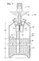
- FIGS. 7 and 8 of the drawing Depicted in FIGS. 7 and 8 of the drawing are first and second examples of an aerosol acoustic texture dispensing systems 420 a and 420 b constructed in accordance with, and embodying, the principles of the present invention.
- FIG. 7 of the drawing depicted at 420 a therein is a first embodiment of an aerosol system for depositing on a surface 422 ( FIGS. 9-12 ) acoustic texture material 424 incorporating particulate material 426 of the present invention.
- FIG. 11 illustrates a target portion 428 of the surface 422 on which acoustic texture material 424 is to be deposited.
- the example aerosol system 420 a comprises a container assembly 430 , a valve assembly 432 , a collection assembly 434 , and an outlet assembly 436 .
- the container 430 defines a product chamber 440 in which the acoustic texture material 424 comprising the particulate material 426 is contained.
- a first portion 442 of the chamber 440 is occupied by the acoustic texture material 424
- a second portion 444 of the chamber 440 is occupied by a pressurized propellant material 446 .
- the example container assembly 430 comprises a can member 450 and a cup member 452 .
- the valve assembly 432 is mounted in a cup opening 454 defined by the cup member 452 and operates in a closed configuration (shown) and an open configuration. In the open configuration, the valve assembly 432 defines a dispensing passageway that allows fluid communication between the interior and the exterior of the container assembly 430 .
- the outlet assembly 436 comprises an actuator member 460 that causes acoustic texture material 424 to be dispensed by the system 420 in a fan shaped spray as will be described in further detail below.
- the actuator member 460 is mounted on the valve assembly 432 such that displacing the actuator member 460 towards the valve assembly 432 places the valve assembly in the open configuration.
- the example valve assembly 432 comprises a valve seat 470 , a valve stem 472 , a valve housing 474 , a dip tube 476 , and a valve spring 478 .
- the valve seat 470 defines a seat opening 470 a and is supported by the cup member 452 .
- the valve stem 472 defines a valve stem opening 472 a and a valve surface 472 b .
- the valve stem 472 is supported by the valve seat 470 such that the valve stem moves within the valve stem opening 472 a between first and second positions, with the first position being shown in FIG. 7 .
- the valve housing 474 is supported by the valve seat 470 within the product chamber 440 .
- the valve housing 474 further supports the dip tube 476 such that the acoustic texture material 424 within can flow into the valve housing 474 when the can is upright.
- the valve spring 478 is supported by the valve housing 474 such that the spring 478 biases the valve stem 472 into the first position.
- the valve stem 472 supports the outlet assembly 436 such that depressing the actuator member 460 towards the cup member 452 forces the valve stem 472 into the second position (not shown) against the force of the valve spring 478 .
- the valve assembly 432 thus operates in the closed configuration and the open configuration as follows.
- the valve spring 478 forces the valve surface 472 b against the valve seat 470 to prevent fluid from flowing through the valve stem opening 472 a .
- the valve surface 472 b is forced away from the valve seat 470 such that fluid can flow from the interior of the valve housing 474 through the valve stem opening 472 a and thus out of the product chamber 440 .
- FIG. 8 of the drawing depicted at 420 b therein is a first embodiment of an aerosol system that may also be used to deposit the acoustic texture material 424 incorporating particulate material 426 of the present invention on the target portion 428 of the surface 422 .
- the example aerosol system 420 b comprises a container assembly 530 , a valve assembly 532 , a collection assembly 534 , and an outlet assembly 536 .
- the container 530 defines a product chamber 540 in which the acoustic texture material 424 comprising the particulate material 426 is contained.
- a first portion 542 of the chamber 540 is occupied by the acoustic texture material 424
- a second portion 544 of the chamber 540 is occupied by a pressurized propellant material 546 .
- the example container assembly 530 comprises a can member 550 and a cup member 552 .
- the valve assembly 532 is mounted in a cup opening 554 define by the cup member 552 and operates in a closed configuration (shown) and an open configuration. In the open configuration, the valve assembly 532 defines a dispensing passageway that allows fluid communication between the interior and the exterior of the container assembly 530 .
- the outlet assembly 536 comprises an actuator member 560 that causes acoustic texture material 424 to be dispensed by the system 420 in a fan shaped spray as will be described in further detail below.
- the actuator member 560 is mounted on the valve assembly 532 such that displacing the actuator member 560 towards the valve assembly 532 places the valve assembly in the open configuration.
- the example valve assembly 532 comprises a valve seat 570 , a valve stem 572 , a valve housing 574 , a dip tube 576 , and a valve spring 578 .
- the valve seat 570 defines a seat opening 570 a and is supported by the cup member 552 .
- the valve stem 572 defines a valve stem opening 572 a and a valve surface 572 b .
- the valve stem 572 is supported by the valve seat 570 such that the valve stem moves within the valve stem opening 572 a between to first and second positions, with the first position being shown in FIG. 8 .
- the valve housing 574 is supported by the valve seat 570 within the product chamber 540 .
- the valve housing 574 further supports the dip tube 576 such that the acoustic texture material 424 within can flow into the valve housing 574 when the can is upright.
- the valve spring 578 is supported by is the valve housing 574 such that the spring 578 biases the valve stem 572 into the first position.
- the valve stem 572 supports the outlet assembly 536 such that depressing the actuator member 560 towards the cup member 552 forces the valve stem 572 into the second position (not shown) against the force of the valve spring 578 .
- the valve assembly 532 thus operates in the closed configuration and the open configuration as follows.
- the valve spring 578 forces the valve surface 572 b against the valve seat 570 to prevent fluid from flowing through the valve stem opening 572 a .
- the valve surface 572 b is forced away from the valve seat 570 such that fluid can flow from the interior of the valve housing 574 through the valve stem opening 572 a and thus out of the product chamber 540 .
- FIGS. 9-12 the use of the aerosol dispensing systems 420 a and 420 b will now be described in further detail. These dispensing systems 420 a and 420 b are used in the same manner and are both identified by reference character 420 in FIGS. 9-12 .
- the dispensing system 420 deposits a fan-shaped spray of acoustic texture material 424 on the target portion 428 of the surface 422 .
- the acoustic texture material 424 covers to the target portion 428 to match the pre-existing acoustic texture material on the surface 422 surrounding the target portion 428 .
- the acoustic texture material comprises a base portion 620 in the form of a flowable liquid.
- the base is portion 620 of the particulate material conventionally comprises a carrier, a filler, and a binder.
- the propellant material 446 , 546 is simply an inert pressurized gas such as air or nitrogen.
- the propellant material 446 , 546 is a material, referred to herein as bi-phase propellant material, that exists in both gaseous and liquid phases within the container assembly 430 , 530 .
- the liquid phase of the propellant material 446 , 546 forms a part of the base portion 620
- the gaseous phase propellant material 446 , 546 occupies the pressurized portion 444 of the container assembly 430 , 530 .
- the pressure within the pressurized portion 444 , 544 of the container assemblies 430 , 530 drops. Under these conditions, a portion of the bi-phase propellant material 446 , 546 in the liquid phase gasifies to re-pressurize the pressurized portion 444 , 544 of the container assembly 430 , 530 .
- the pressure within the pressurized portion 444 , 544 is thus under most conditions sufficient to force the acoustic texture material 424 out of the container assembly 430 , 530 along the dispensing passageway when the valve assembly 432 , 532 is in the open configuration.
- the propellant material 446 , 546 may thus be a pressurized inert gas such as air or nitrogen.
- the present invention is of particular significance when the propellant material is a bi-phase propellant material such as di-methyl ethylene (DME) or any one of a number of hydrocarbon propellants such as those available in the industry as A-40 and A-70.
- the advantage of using bi-phase propellant materials is that the pressure within the pressurized portion 444 , 544 of the container assembly 430 , 530 is kept at a relatively constant, relatively low level as the level of acoustic texture material 424 drops. This constant, low level pressure allows the texture material 424 to be dispensed in many small bursts instead of in a few large bursts, as is the case when pressurized inert gases are used as the propellant material 446 , 546 .
- DME di-methyl ethylene
- particulate materials 426 suitable for use in acoustic texture materials are incompatible with bi-phase propellant materials.
- polystyrene chips are commonly used in acoustic texture materials dispensed using commercial hopper guns.
- polystyrene chips dissolve in the bi-phase propellant materials of which the Applicant is aware.
- urethane foam materials and melamine foam materials may be used as the particulate material 426 with bi-phase propellant materials such as DME and hydrocarbon propellants such as A-40 and A-70.
- Melamine foam materials in particular are easily chopped up using conventional material processors (e.g., a food blender) into irregular shapes that match the appearance and function of polystyrene chips.
- material processors e.g., a food blender
- Melamine foam materials are already commonly used in building applications and have desirable fire retardant, thermal, and acoustic properties.
- the base portion 620 may be the same as a conventional base used in commercially available acoustic texture materials. Instead of polystyrene chips, however, urethane and/or melamine foam is chopped up into particles of an appropriate size and use as the particulate. In addition, a bi-phase propellant material is used to form part of the carrier portion of the base portion 620 .
Abstract
Description
Claims (8)
Priority Applications (3)
| Application Number | Priority Date | Filing Date | Title |
|---|---|---|---|
| US12/859,195 US8042713B2 (en) | 2004-10-08 | 2010-08-18 | Aerosol systems and methods for dispensing texture material |
| US13/280,924 US8336742B2 (en) | 2004-10-08 | 2011-10-25 | Aerosol systems and methods for dispensing texture material |
| US13/715,946 US20130102696A1 (en) | 2004-10-08 | 2012-12-14 | Aerosol Systems and Methods for Dispensing Texture Material |
Applications Claiming Priority (6)
| Application Number | Priority Date | Filing Date | Title |
|---|---|---|---|
| US61723604P | 2004-10-08 | 2004-10-08 | |
| US11/027,219 US7374068B2 (en) | 2004-10-08 | 2004-12-29 | Particulate materials for acoustic texture material |
| US67569705P | 2005-04-27 | 2005-04-27 | |
| US11/413,659 US7487893B1 (en) | 2004-10-08 | 2006-04-27 | Aerosol systems and methods for dispensing texture material |
| US98213307A | 2007-10-31 | 2007-10-31 | |
| US12/859,195 US8042713B2 (en) | 2004-10-08 | 2010-08-18 | Aerosol systems and methods for dispensing texture material |
Related Parent Applications (1)
| Application Number | Title | Priority Date | Filing Date |
|---|---|---|---|
| US98213307A Continuation | 2004-10-08 | 2007-10-31 |
Related Child Applications (1)
| Application Number | Title | Priority Date | Filing Date |
|---|---|---|---|
| US13/280,924 Continuation US8336742B2 (en) | 2004-10-08 | 2011-10-25 | Aerosol systems and methods for dispensing texture material |
Publications (2)
| Publication Number | Publication Date |
|---|---|
| US20110036872A1 US20110036872A1 (en) | 2011-02-17 |
| US8042713B2 true US8042713B2 (en) | 2011-10-25 |
Family
ID=40342829
Family Applications (8)
| Application Number | Title | Priority Date | Filing Date |
|---|---|---|---|
| US11/413,659 Active US7487893B1 (en) | 2004-10-08 | 2006-04-27 | Aerosol systems and methods for dispensing texture material |
| US12/368,960 Active US7784649B2 (en) | 2004-10-08 | 2009-02-10 | Aerosol systems and methods for dispensing texture material |
| US12/859,195 Expired - Fee Related US8042713B2 (en) | 2004-10-08 | 2010-08-18 | Aerosol systems and methods for dispensing texture material |
| US12/873,121 Expired - Fee Related US8172113B2 (en) | 2004-10-08 | 2010-08-31 | Aerosol systems and methods for dispensing texture material |
| US13/280,924 Active US8336742B2 (en) | 2004-10-08 | 2011-10-25 | Aerosol systems and methods for dispensing texture material |
| US13/466,989 Active US8622255B2 (en) | 2004-10-08 | 2012-05-08 | Aerosol systems and methods for dispensing texture material |
| US13/715,946 Abandoned US20130102696A1 (en) | 2004-10-08 | 2012-12-14 | Aerosol Systems and Methods for Dispensing Texture Material |
| US14/147,474 Expired - Fee Related US9004323B2 (en) | 2004-10-08 | 2014-01-03 | Aerosol systems and methods for dispensing texture material |
Family Applications Before (2)
| Application Number | Title | Priority Date | Filing Date |
|---|---|---|---|
| US11/413,659 Active US7487893B1 (en) | 2004-10-08 | 2006-04-27 | Aerosol systems and methods for dispensing texture material |
| US12/368,960 Active US7784649B2 (en) | 2004-10-08 | 2009-02-10 | Aerosol systems and methods for dispensing texture material |
Family Applications After (5)
| Application Number | Title | Priority Date | Filing Date |
|---|---|---|---|
| US12/873,121 Expired - Fee Related US8172113B2 (en) | 2004-10-08 | 2010-08-31 | Aerosol systems and methods for dispensing texture material |
| US13/280,924 Active US8336742B2 (en) | 2004-10-08 | 2011-10-25 | Aerosol systems and methods for dispensing texture material |
| US13/466,989 Active US8622255B2 (en) | 2004-10-08 | 2012-05-08 | Aerosol systems and methods for dispensing texture material |
| US13/715,946 Abandoned US20130102696A1 (en) | 2004-10-08 | 2012-12-14 | Aerosol Systems and Methods for Dispensing Texture Material |
| US14/147,474 Expired - Fee Related US9004323B2 (en) | 2004-10-08 | 2014-01-03 | Aerosol systems and methods for dispensing texture material |
Country Status (1)
| Country | Link |
|---|---|
| US (8) | US7487893B1 (en) |
Cited By (10)
| Publication number | Priority date | Publication date | Assignee | Title |
|---|---|---|---|---|
| US20110281030A1 (en) * | 2004-10-08 | 2011-11-17 | Homax Products, Inc. | Particulate materials for acoustic texture material |
| US20120097703A1 (en) * | 2004-10-08 | 2012-04-26 | Homax Products, Inc. | Aerosol Systems and Methods for Dispensing Texture Material |
| US8251255B1 (en) | 2004-07-02 | 2012-08-28 | Homax Products, Inc. | Aerosol spray texture apparatus for a particulate containing material |
| US8726450B2 (en) | 2007-02-07 | 2014-05-20 | Homax Products, Inc. | Scraper system and methods |
| US9382060B1 (en) | 2007-04-05 | 2016-07-05 | Homax Products, Inc. | Spray texture material compositions, systems, and methods with accelerated dry times |
| US9415927B2 (en) | 2007-04-04 | 2016-08-16 | Homax Products, Inc. | Spray texture material compositions, systems, and methods with anti-corrosion characteristics |
| US9435120B2 (en) | 2013-03-13 | 2016-09-06 | Homax Products, Inc. | Acoustic ceiling popcorn texture materials, systems, and methods |
| USD787326S1 (en) | 2014-12-09 | 2017-05-23 | Ppg Architectural Finishes, Inc. | Cap with actuator |
| US9776785B2 (en) | 2013-08-19 | 2017-10-03 | Ppg Architectural Finishes, Inc. | Ceiling texture materials, systems, and methods |
| US9808816B1 (en) | 2016-08-26 | 2017-11-07 | Gemini Holdings, LLC | Spray gun system |
Families Citing this family (24)
| Publication number | Priority date | Publication date | Assignee | Title |
|---|---|---|---|---|
| US5310095A (en) * | 1992-02-24 | 1994-05-10 | Djs&T Limited Partnership | Spray texturing apparatus and method having a plurality of dispersing tubes |
| US20050161531A1 (en) | 2004-01-28 | 2005-07-28 | Greer Lester R.Jr. | Texture material for covering a repaired portion of a textured surface |
| US8940207B2 (en) | 2010-08-03 | 2015-01-27 | Velcro Industries B.V. | Pelletizing |
| EP2600745B1 (en) | 2010-08-03 | 2016-04-20 | Velcro Industries B.V. | Touch fastening |
| US8523088B2 (en) | 2011-01-18 | 2013-09-03 | Velcro Industries B.V. | Particle spraying |
| US9156042B2 (en) | 2011-07-29 | 2015-10-13 | Homax Products, Inc. | Systems and methods for dispensing texture material using dual flow adjustment |
| US9248457B2 (en) | 2011-07-29 | 2016-02-02 | Homax Products, Inc. | Systems and methods for dispensing texture material using dual flow adjustment |
| US10813630B2 (en) | 2011-08-09 | 2020-10-27 | Corquest Medical, Inc. | Closure system for atrial wall |
| US10314594B2 (en) | 2012-12-14 | 2019-06-11 | Corquest Medical, Inc. | Assembly and method for left atrial appendage occlusion |
| US10307167B2 (en) | 2012-12-14 | 2019-06-04 | Corquest Medical, Inc. | Assembly and method for left atrial appendage occlusion |
| US9622563B2 (en) * | 2012-04-16 | 2017-04-18 | The Procter & Gamble Company | Plastic packages for dispensing aerosol products having improved crazing resistance and sustainability |
| US9156602B1 (en) | 2012-05-17 | 2015-10-13 | Homax Products, Inc. | Actuators for dispensers for texture material |
| KR101428358B1 (en) * | 2013-01-08 | 2014-08-07 | 엘지이노텍 주식회사 | The sensor module |
| US9566443B2 (en) | 2013-11-26 | 2017-02-14 | Corquest Medical, Inc. | System for treating heart valve malfunction including mitral regurgitation |
| US9315314B2 (en) * | 2014-06-27 | 2016-04-19 | Westrock Dispensing Systems, Inc. | Dual actuated aerosol devices |
| US10842626B2 (en) | 2014-12-09 | 2020-11-24 | Didier De Canniere | Intracardiac device to correct mitral regurgitation |
| BE1024213B1 (en) * | 2016-11-04 | 2017-12-13 | Altachem Nv | Valve |
| GB2560993B (en) * | 2017-03-31 | 2020-01-08 | The Salford Valve Company Ltd | A valve assembly for an aerosol spray device |
| US10239185B2 (en) | 2017-08-23 | 2019-03-26 | Aeroetch Holdings, Inc. | Self-powered pressurized granular particle ejector tool with remote operation |
| CN108442665B (en) * | 2018-02-08 | 2019-10-25 | 李友洪 | A kind of paint brush |
| EP4003875B1 (en) | 2019-07-26 | 2023-08-30 | The Procter & Gamble Company | A valve assembly for dispensers |
| US20210025503A1 (en) * | 2019-07-26 | 2021-01-28 | The Procter & Gamble Company | Valve Assembly for Dispensers |
| WO2021220081A1 (en) * | 2020-04-27 | 2021-11-04 | 花王株式会社 | Foam dispensing container |
| ES1293544Y (en) * | 2022-06-01 | 2022-10-25 | Arribas Rodriguez Jorge | Rough finish spray varnish |
Citations (114)
| Publication number | Priority date | Publication date | Assignee | Title |
|---|---|---|---|---|
| US2686652A (en) | 1951-01-29 | 1954-08-17 | Viking Valve Company | Valve apparatus |
| US2763406A (en) | 1952-06-05 | 1956-09-18 | James H Countryman | Valve construction for dispensing containers |
| US2764454A (en) | 1953-12-29 | 1956-09-25 | Albert L Edelstein | Aerosol apparatus for decorative coating and process for making said apparatus |
| US2785926A (en) | 1953-11-23 | 1957-03-19 | Lataste Bernard | Means for atomizing liquid |
| US2831618A (en) | 1956-04-12 | 1958-04-22 | Dev Res Inc | Dispensing valve dischargeable in upright position |
| US2839225A (en) | 1956-06-18 | 1958-06-17 | Dev Res Inc | Dispenser valve providing controlled flow and quick gassing |
| US2965270A (en) | 1957-06-12 | 1960-12-20 | Dev Res Inc | Dispensing valve having spring of elastic material |
| US3191809A (en) | 1961-12-29 | 1965-06-29 | Pillsbury Co | Pressurized container having a plurality of selectively attachable nozzles |
| US3196819A (en) | 1962-02-28 | 1965-07-27 | Rudolf Lechner Kommanditgeseil | Method of producing seamless metal bottles and an apparatus for carrying the method |
| US3346195A (en) | 1964-10-22 | 1967-10-10 | Sprayon Products | Aerosol spray device |
| US3415425A (en) | 1966-11-15 | 1968-12-10 | Johnson & Johnson | Aerosol dispenser |
| US3433391A (en) | 1966-03-07 | 1969-03-18 | Continental Can Co | Dispensing container with collapsible compartment |
| US3450314A (en) | 1967-05-31 | 1969-06-17 | Clayton Corp | Dispensing valve having rubber-like dispensing head |
| US3467283A (en) | 1968-01-18 | 1969-09-16 | Continental Can Co | Dispensing container with collapsible compartment |
| US3482738A (en) | 1966-03-15 | 1969-12-09 | Continental Can Co | Aerosol container and valve therefor |
| US3544258A (en) | 1963-08-19 | 1970-12-01 | Aerosol Tech Inc | Self-propelled liquid dispenser containing an antiperspirant aluminum salt |
| US3548564A (en) | 1966-05-10 | 1970-12-22 | Sterigard Corp | Process for fabricating a pressurized container |
| US3592359A (en) | 1969-05-27 | 1971-07-13 | Leonard L Marraffino | Spring-valve member in pressurized two fluid dispenser |
| US3700136A (en) | 1966-03-25 | 1972-10-24 | Continental Can Co | End unit and liner for aerosol containers |
| US3788521A (en) | 1972-07-10 | 1974-01-29 | Laauwe Robert H | Aerosol package |
| US3806005A (en) | 1969-03-26 | 1974-04-23 | S Prussin | Aerosol container with plug-in cap and valve structure |
| US3828977A (en) | 1972-06-14 | 1974-08-13 | Continental Can Co | Compartment bag assembly for dispensing containers |
| US3862705A (en) | 1973-09-07 | 1975-01-28 | Rca Corp | Hand-held dispenser with mixing valve and pressurizing valve |
| US3913842A (en) | 1973-12-14 | 1975-10-21 | Block Drug Co | Spray head for aerosol can |
| US3932973A (en) | 1974-11-18 | 1976-01-20 | Moore Alvin E | Insubars |
| US3938708A (en) | 1974-08-15 | 1976-02-17 | Norman D. Burger | Aerosol dispensing system |
| US3989165A (en) | 1973-02-23 | 1976-11-02 | Continental Can Company, Inc. | Compartment bag for aerosol container |
| US3992003A (en) | 1975-10-24 | 1976-11-16 | Visceglia Marco P | Aerosol container having sealed propellant means |
| US4032064A (en) | 1976-01-05 | 1977-06-28 | The Continental Group, Inc. | Barrier bag assembly for aerosol container |
| US4036673A (en) | 1973-12-28 | 1977-07-19 | Congoleum Corporation | Method for installing surface covering or the like |
| US4045860A (en) | 1975-05-07 | 1977-09-06 | Cebal | Method of assembling an aerosol dispenser |
| US4049853A (en) | 1974-10-01 | 1977-09-20 | Norman Patrick Tortolo | Terrazzo structure having a sub-surface and an intermediate impermeable sheet |
| US4089443A (en) | 1976-12-06 | 1978-05-16 | Zrinyi Nicolaus H | Aerosol, spray-dispensing apparatus |
| US4117951A (en) | 1975-05-07 | 1978-10-03 | Cebal | Aerosol dispenser liner |
| US4148416A (en) | 1976-08-20 | 1979-04-10 | Metal Box Limited | Aerosol containers |
| US4154378A (en) | 1976-11-04 | 1979-05-15 | L'oreal | Metering valve for pressurized container |
| USRE30093E (en) | 1975-01-27 | 1979-09-11 | Aerosol dispensing system | |
| US4171757A (en) | 1976-06-08 | 1979-10-23 | Diamond George B | Pressurized barrier pack |
| US4185758A (en) | 1978-08-01 | 1980-01-29 | The Continental Group, Inc. | Compartmentalized aerosol container |
| US4187959A (en) | 1978-08-17 | 1980-02-12 | The Continental Group, Inc. | Propellantless aerosol dispensing system |
| US4198365A (en) | 1979-01-08 | 1980-04-15 | The Continental Group, Inc. | Method of applying product bags in aerosol barrier packages |
| US4238264A (en) | 1979-01-15 | 1980-12-09 | The Continental Group, Inc. | Aerosol barrier package with a bag adhesively attached to the curl |
| US4293353A (en) | 1978-11-03 | 1981-10-06 | The Continental Group, Inc. | Sealing-attaching system for bag type aerosol containers |
| US4308973A (en) | 1978-06-30 | 1982-01-05 | The Continental Group, Inc. | Compartmented aerosol container |
| US4322020A (en) | 1978-05-02 | 1982-03-30 | Raymond Stone | Invertible pump sprayer |
| US4346743A (en) | 1980-12-19 | 1982-08-31 | The Continental Group, Inc. | Product bag for aerosol container and method of utilizing the same to facilitate filling with propellant |
| US4370930A (en) | 1980-12-29 | 1983-02-01 | Ford Motor Company | End cap for a propellant container |
| US4401272A (en) | 1982-05-17 | 1983-08-30 | Minnesota Mining And Manufacturing Company | Aerosol fan sprayhead |
| US4401271A (en) | 1981-07-10 | 1983-08-30 | Minnesota Mining And Manufacturing Company | Aerosal fan spray head |
| US4417674A (en) | 1978-04-13 | 1983-11-29 | Coster Tecnologie Speciali S.P.A. | Valve for the admixture of fluids and delivery of the resulting mixture |
| US4442959A (en) | 1981-04-30 | 1984-04-17 | Luigi Del Bon | Self-closing valve-and-lid assembly |
| US4641765A (en) | 1984-10-05 | 1987-02-10 | Diamond George B | Expandable pressurized barrier container |
| US4854482A (en) | 1987-02-23 | 1989-08-08 | Hilti Aktiengesellschaft | Dispensing device for flowable masses |
| DE3806991A1 (en) | 1987-05-15 | 1989-09-14 | Kern Ralf M Dipl Ing | Propellent gas pressure container |
| US4870805A (en) | 1987-06-19 | 1989-10-03 | L'oreal | Method of packaging a fluid under pressure, and packaging container for use with the method |
| US4896832A (en) | 1987-09-07 | 1990-01-30 | Bespak Plc | Dispensing apparatus for metered quantities of pressurised fluid |
| US4940171A (en) | 1989-05-18 | 1990-07-10 | Gilroy Gordon C | Aerosol package having compressed gas propellant and vapor tap of minute size |
| US4949871A (en) | 1989-02-09 | 1990-08-21 | Aerosol Systems, Inc. | Barrier pack product dispensing cans |
| US4969577A (en) | 1987-06-26 | 1990-11-13 | Werding Winfried J | Apparatus to provide for the storage and the controlled delivery of products that are under pressure |
| US5007556A (en) | 1990-04-18 | 1991-04-16 | Block Drug Company, Inc. | Metering dispenser |
| US5037011A (en) | 1990-04-30 | 1991-08-06 | Woods John R | Spray-on wall surface texture dispenser |
| US5038964A (en) | 1988-05-10 | 1991-08-13 | L'oreal | Pressurized container including a valve and a device for actuating the valve |
| US5059187A (en) | 1988-11-30 | 1991-10-22 | Dey Laboratories, Inc. | Method for the cleansing of wounds using an aerosol container having liquid wound cleansing solution |
| US5115944A (en) | 1990-08-14 | 1992-05-26 | Illinois Tool Works Inc. | Fluid dispenser having a collapsible inner bag |
| US5126086A (en) | 1989-09-22 | 1992-06-30 | Lechner Gmbh | Method for producing a container having an inside bag |
| US5188263A (en) | 1991-07-22 | 1993-02-23 | John R. Woods | Spray-on wall surface texture dispenser |
| US5211317A (en) | 1992-06-18 | 1993-05-18 | Diamond George Bernard | Low pressure non-barrier type, valved dispensing can |
| US5310095A (en) | 1992-02-24 | 1994-05-10 | Djs&T Limited Partnership | Spray texturing apparatus and method having a plurality of dispersing tubes |
| US5341970A (en) | 1993-02-19 | 1994-08-30 | Woods John R | Acoustic ceiling patch spray |
| US5421519A (en) | 1994-04-22 | 1995-06-06 | Woods; John R. | Adjustable nozzle |
| USD358989S (en) | 1994-04-22 | 1995-06-06 | Woods John R | Adjustable nozzle for a pressurized container |
| US5450983A (en) | 1993-03-12 | 1995-09-19 | Djs&T, Limited Partnership | Aerosol spray texture apparatus and method for a particulate containing material |
| US5476879A (en) | 1993-02-19 | 1995-12-19 | Spraytex, Inc. | Acoustic ceiling patch spray |
| US5505344A (en) | 1993-02-19 | 1996-04-09 | Spraytex, Inc. | Acoustic ceiling patch spray |
| US5524798A (en) | 1992-02-24 | 1996-06-11 | Djs&T Limited Partnership | Spray texturing nozzles having variable orifice |
| US5605259A (en) | 1995-04-07 | 1997-02-25 | Homax Products, Inc. | Method and apparatus for covering irregularities in a wall surface |
| US5639026A (en) | 1994-04-22 | 1997-06-17 | Woods; John | Directly mountable adjustable spray nozzle |
| US5655691A (en) | 1992-02-24 | 1997-08-12 | Homax Products, Inc. | Spray texturing device |
| US5695788A (en) | 1996-04-09 | 1997-12-09 | Spraytex, Inc. | Wall texture tool |
| US5715975A (en) | 1992-02-24 | 1998-02-10 | Homax Products, Inc. | Aerosol spray texturing devices |
| US5921446A (en) | 1996-04-02 | 1999-07-13 | Homax Products, Inc. | Aerosol spray texturing systems and methods |
| US5934518A (en) | 1992-02-24 | 1999-08-10 | Homax Products, Inc. | Aerosol texture assembly and method |
| US5941462A (en) | 1997-03-25 | 1999-08-24 | John R. Woods | Variable spray nozzle for product sprayer |
| US6000583A (en) | 1992-02-24 | 1999-12-14 | Homax Products, Inc. | Aerosol spray texturing devices |
| US6112945A (en) | 1999-05-14 | 2000-09-05 | Spraytex, Inc. | Aerosol valve assembly for spraying viscous materials or materials with large particulates |
| US6152335A (en) | 1993-03-12 | 2000-11-28 | Homax Products, Inc. | Aerosol spray texture apparatus for a particulate containing material |
| USD438111S1 (en) | 2000-03-24 | 2001-02-27 | Spraytex, Inc. | Variable spray nozzle |
| US6225393B1 (en) | 1999-05-14 | 2001-05-01 | Spraytex, Inc. | Hardenable exterior texture material in aerosol form |
| US6299686B1 (en) | 1997-07-11 | 2001-10-09 | Gregory B. Mills | Drywall taping and texture system using pump |
| US6299679B1 (en) | 1999-09-14 | 2001-10-09 | Western Mobile New Mexico, Inc. | Ready-to-use stucco composition and method |
| US6328185B1 (en) | 1992-02-24 | 2001-12-11 | Homax Products, Inc. | Aerosol spray texturing device with deformable outlet member |
| US6386402B1 (en) | 2000-03-27 | 2002-05-14 | Spraytex, Inc. | Aqueous quick dry sprayable drywall texture |
| US6415964B2 (en) | 1999-05-14 | 2002-07-09 | Spraytex, Inc. | Aerosol valve assembly for spraying viscous materials or materials with large particulates |
| US20020108339A1 (en) | 2001-02-15 | 2002-08-15 | Sacks Industrial Corp. | Stucco fastening system |
| USD468980S1 (en) | 2002-01-11 | 2003-01-21 | Spraytex, Inc. | Device for spreading substances having a paste like consistency |
| US6641864B2 (en) | 1999-08-16 | 2003-11-04 | Spraytex, Inc. | More controllable acoustic spray patch compositions |
| US6666352B1 (en) * | 2000-09-05 | 2003-12-23 | Spraytex, Inc. | Sand finish spray texture |
| US6712238B1 (en) | 2002-10-08 | 2004-03-30 | Spraytex, Inc. | Drywall taping and texture system using bladder pump with pneumatic flip/flop logic remote control |
| US6726066B2 (en) | 1999-05-14 | 2004-04-27 | Spraytex, Inc. | Side-feeding aerosol valve assembly |
| US6797051B2 (en) | 1999-08-16 | 2004-09-28 | Spraytex, Inc. | More controllable fibrous patch spray |
| US6848601B2 (en) | 2002-03-14 | 2005-02-01 | Homax Products, Inc. | Aerosol systems and methods for mixing and dispensing two-part materials |
| US6883688B1 (en) | 1992-02-24 | 2005-04-26 | Homax Products, Inc. | Aerosol spray texturing systems and methods |
| US6910608B2 (en) | 2002-11-12 | 2005-06-28 | Homax Products, Inc. | Storage systems and methods for aerosol accessories |
| US20050161531A1 (en) | 2004-01-28 | 2005-07-28 | Greer Lester R.Jr. | Texture material for covering a repaired portion of a textured surface |
| US7059497B2 (en) | 1999-05-14 | 2006-06-13 | Spraytex, Inc. | Multiple side-feeding aerosol valve assembly |
| US7063236B2 (en) | 2002-03-14 | 2006-06-20 | Homax Products, Inc. | Aerosol systems and methods for mixing and dispensing two-part materials |
| US20070219310A1 (en) | 2006-03-17 | 2007-09-20 | Woods John R | Paint ready sprayable material |
| US7278590B1 (en) | 1992-02-24 | 2007-10-09 | Homax Products, Inc. | Systems and methods for applying texture material to ceiling surfaces |
| US7303152B2 (en) | 2006-03-17 | 2007-12-04 | Woods John R | Variable aerosol nozzle |
| US7374068B2 (en) | 2004-10-08 | 2008-05-20 | Homax Products, Inc. | Particulate materials for acoustic texture material |
| US7487893B1 (en) * | 2004-10-08 | 2009-02-10 | Homax Products, Inc. | Aerosol systems and methods for dispensing texture material |
| US7500621B2 (en) | 2003-04-10 | 2009-03-10 | Homax Products, Inc. | Systems and methods for securing aerosol systems |
| US7600659B1 (en) | 1992-02-24 | 2009-10-13 | Homax Products, Inc. | Systems and methods for applying texture material to ceiling surfaces |
| US7677420B1 (en) * | 2004-07-02 | 2010-03-16 | Homax Products, Inc. | Aerosol spray texture apparatus for a particulate containing material |
Family Cites Families (439)
| Publication number | Priority date | Publication date | Assignee | Title |
|---|---|---|---|---|
| US568876A (en) | 1896-10-06 | Hose-nozzle | ||
| US582397A (en) | 1897-05-11 | John shone | ||
| US604151A (en) | 1898-05-17 | Spraying device | ||
| DE634230C (en) | 1936-08-21 | Otto Helmer Lawaetz | Device for atomizing paints and oils | |
| US351968A (en) | 1886-11-02 | Derrick | ||
| CA770467A (en) | 1967-10-31 | C. Hug Richard | Combination valve spout and spray head assembly | |
| US579418A (en) | 1897-03-23 | bookwaltee | ||
| US625594A (en) | 1899-05-23 | Pneumatic sprayer | ||
| US208330A (en) | 1878-09-24 | Improvement in hose-nozzles | ||
| US658586A (en) | 1899-08-17 | 1900-09-25 | Meinhard Reiling | Fire-hose. |
| US931757A (en) | 1907-01-02 | 1909-08-24 | Pneumatic Machinery Cleaner Company | Pneumatic machinery-cleaner. |
| DE210449C (en) | 1907-02-22 | 1909-05-29 | ||
| US941671A (en) | 1908-02-17 | 1909-11-30 | James Winthrop Campbell | Sprinkler. |
| US930095A (en) | 1909-02-10 | 1909-08-03 | Frederic S Seagrave | Nozzle. |
| US1093907A (en) | 1913-03-10 | 1914-04-21 | Henry Birnbaum | Nozzle. |
| FR463476A (en) | 1913-09-18 | 1914-02-24 | Vital Habran | Oxy-acetylene autogenous welding torch |
| US1162170A (en) | 1914-06-01 | 1915-11-30 | Johnson Service Co | Automatic control device. |
| US1154974A (en) | 1915-03-22 | 1915-09-28 | Burr Custer | Welding-torch. |
| US1294190A (en) | 1916-05-13 | 1919-02-11 | Herman Edward Stuercke | Air-brush and similar apparatus. |
| US1332544A (en) | 1919-03-08 | 1920-03-02 | Spray Engineering Co | Means for applying coating |
| US1486156A (en) | 1919-08-13 | 1924-03-11 | Needham Joseph | Hydrocarbon burner |
| US1609465A (en) | 1922-04-01 | 1926-12-07 | Spray Painting & Finishing Equ | Tool for applying coating |
| US1650686A (en) | 1925-11-07 | 1927-11-29 | Binks Spray Equipment Co | Spray gun |
| US1656132A (en) | 1926-02-03 | 1928-01-10 | Claude C Arrasmith | Valve |
| US1643969A (en) | 1926-08-26 | 1927-10-04 | Hopkins Spray Equipment Compan | Means for controlling the distribution of liquids |
| US1755329A (en) | 1927-03-14 | 1930-04-22 | Lawrence E Mccormack | Pneumatic gun for applying mortar |
| US1770011A (en) | 1927-10-27 | 1930-07-08 | Emmett V Poston | Steam and clay mixing nozzle |
| US1674510A (en) | 1928-01-03 | 1928-06-19 | Nore A Hagman | Shaving pad |
| US1809073A (en) | 1928-10-12 | 1931-06-09 | John F Schylander | Spray |
| CH150620A (en) | 1929-01-29 | 1931-11-15 | Bakelite Gmbh | Process for the production of lacquers and varnishes. |
| US1863924A (en) | 1930-04-28 | 1932-06-21 | W E Dunn Mfg Company | Spraying device |
| US1988017A (en) | 1933-01-24 | 1935-01-15 | Anthony T Norwick | Spraying apparatus |
| US2032803A (en) | 1934-06-22 | 1936-03-03 | John M Hunter | Door control mechanism |
| US2149930A (en) | 1934-08-23 | 1939-03-07 | Wil X M F G Corp | Nozzle for spraying devices |
| BE412382A (en) | 1934-11-26 | |||
| GB491396A (en) | 1936-07-14 | 1938-09-01 | Bosch Robert | Improvements in or relating to spraying apparatus |
| BE425501A (en) | 1937-01-25 | 1938-01-31 | ||
| US2197052A (en) | 1937-02-01 | 1940-04-16 | Lowen Stanley | Combination applicator and closure |
| US2127188A (en) | 1937-09-11 | 1938-08-16 | Akron Brass Mfg Company Inc | Mist-producing nozzle |
| GB508734A (en) | 1938-03-30 | 1939-07-05 | Broughton Haggis | Improvements in spray producers |
| US2198271A (en) | 1938-06-30 | 1940-04-23 | Ingersoll W Mccallum | Plastering machine |
| NL54321C (en) | 1939-02-24 | |||
| US2307014A (en) | 1939-11-02 | 1943-01-05 | Charles F Becker | Fire hose nozzle |
| US2353318A (en) | 1940-03-08 | 1944-07-11 | Linde Air Prod Co | Nozzle for desurfacing metal |
| US2305269A (en) | 1941-06-07 | 1942-12-15 | Moreland William | Spraying device |
| US2361407A (en) | 1942-08-11 | 1944-10-31 | Mcnair Joseph | Applicator |
| US2388093A (en) | 1942-10-08 | 1945-10-30 | Smith Frank | Liquid delivery apparatus |
| US2320964A (en) | 1942-10-27 | 1943-06-01 | Harry A Yates | Safety air nozzle |
| US2565954A (en) | 1946-02-23 | 1951-08-28 | Gaspray Corp | Valved closure for vessel with fluid under pressure, having manually operated valve actuator |
| GB675664A (en) | 1948-02-26 | 1952-07-16 | Burgess Vibrocrafters | Improvements in or relating to a sprayer or atomizer |
| US2530808A (en) | 1949-01-12 | 1950-11-21 | Vincent C Cerasi | Waterworks device |
| US2612293A (en) | 1949-01-21 | 1952-09-30 | Michel Daniel | Container closure member having a dispensing valve therein |
| US2723200A (en) | 1950-11-08 | 1955-11-08 | Dev Res Inc | Method for packaging viscous food preparations |
| US2704690A (en) | 1952-08-01 | 1955-03-22 | Eichenauer Rudolf | Spray gun |
| GB726455A (en) | 1953-04-17 | 1955-03-16 | Lister Welch | Improvements in or relating to electric spray-guns |
| US2790680A (en) | 1955-01-27 | 1957-04-30 | Gordon T Rosholt | Combination hose nozzle, valve, and swivel coupler |
| US2801880A (en) | 1956-04-03 | 1957-08-06 | Rienecker Fred | Hopper spray gun |
| US2908446A (en) | 1956-05-18 | 1959-10-13 | Strouse Inc | Spray tube |
| BE565000A (en) | 1957-02-21 | 1900-01-01 | ||
| US2932434A (en) | 1957-11-26 | 1960-04-12 | John J Baessler | Means for dispensing liquid concentrate drop by drop |
| US2962743A (en) | 1957-12-10 | 1960-12-06 | United Shoe Machinery Corp | Shoe cream applicators with laminated plastic sponge pads |
| US2887274A (en) | 1958-02-20 | 1959-05-19 | Swan V Swenson | Spray gun for applying plaster and the like |
| US3072953A (en) | 1958-05-07 | 1963-01-15 | United Shoe Machinery Corp | Applicator tubes |
| US2968441A (en) | 1958-08-15 | 1961-01-17 | Doyle D Holcomb | Spray nozzle assembly for use with aerosol can |
| US2999646A (en) | 1958-08-16 | 1961-09-12 | Charles S Tanner Company | Spray gun |
| US2997243A (en) | 1958-08-27 | 1961-08-22 | George E Kolb | Aerosol container |
| US3083872A (en) | 1959-01-02 | 1963-04-02 | Meshberg Philip | Selective dispensing nozzle |
| US2976897A (en) | 1959-02-10 | 1961-03-28 | Beckworth Dixie | Reusable pressurized canister |
| GB867713A (en) | 1959-02-27 | 1961-05-10 | Airtech Ltd | A new or improved nozzle for projecting liquid from a hose or the like |
| US3016561A (en) | 1959-09-04 | 1962-01-16 | Hulsh Sheldon David | Squeezable tube dispenser construction |
| US3167525A (en) | 1960-03-31 | 1965-01-26 | California Research Corp | Metal dispersions in polymers |
| US3116856A (en) | 1960-08-24 | 1964-01-07 | Aerosol Tech Inc | Actuator for aerosol valve, provided with a pivoted directional spout |
| US3135007A (en) | 1961-02-17 | 1964-06-02 | Metal Box Co Ltd | Applicator type containers |
| US3107059A (en) | 1961-08-15 | 1963-10-15 | Electrolux Ab | Spraying device |
| DE1926796U (en) | 1961-10-12 | 1965-11-11 | Heidolph Elektro K G | FAN. |
| NL286928A (en) | 1961-12-20 | |||
| US3116879A (en) | 1962-01-30 | 1964-01-07 | Charles S Tanner Company | Spray head for spray gun |
| US3121906A (en) | 1962-05-29 | 1964-02-25 | Jerclaydon Inc | Squeezable tube dispenser |
| US3198394A (en) | 1962-11-16 | 1965-08-03 | Lefer Samuel | Pressurized dispensers |
| GB977860A (en) | 1962-12-18 | 1964-12-16 | Nat Res Dev | Improvements in and relating to nozzles |
| GB1023884A (en) | 1963-07-04 | 1966-03-30 | Chiswick Products Ltd | Improvements relating to dispensers for liquid,powder or the like materials |
| US3207444A (en) | 1963-08-02 | 1965-09-21 | Dura Corp | Water spray attachment having air control and liquid additive passages connected to a mixing chamber |
| US3148806A (en) | 1963-09-03 | 1964-09-15 | Meshberg Philip | Directional applicator |
| FR1354522A (en) | 1963-09-26 | 1964-03-06 | Interchangeable tip for tracer device with humection | |
| US3307788A (en) | 1963-12-03 | 1967-03-07 | Koppers Co Inc | Field application of foam coatings |
| US3236459A (en) | 1963-12-16 | 1966-02-22 | Thomas P Mcritchie | Apparatus for spraying materials |
| US3258208A (en) | 1964-05-07 | 1966-06-28 | Seaquist Valve Co | Aerosol valve |
| US3246850A (en) | 1964-05-20 | 1966-04-19 | Corn Products Co | Dual spray head |
| US3390121A (en) | 1964-06-16 | 1968-06-25 | Argus Chem | Color indication in polyester resin curing |
| US3284007A (en) | 1964-11-03 | 1966-11-08 | Aerosol Tech Inc | Reversible aerosol spray tip |
| US3317140A (en) | 1964-11-12 | 1967-05-02 | John J Smith | Aerosol spray nozzle |
| US3314571A (en) | 1964-12-30 | 1967-04-18 | Seaquist Valve Co | Mother-daughter aerosols and valve button therefor |
| US3216628A (en) | 1965-01-12 | 1965-11-09 | Rust Oleum Corp | Paint spray can unit and extension attachment therefor |
| US3305144A (en) | 1965-03-01 | 1967-02-21 | Valve Corp Of America | Dispenser for disposable aerosol container, with valved conduit for remote dischargeof its contents |
| US3342382A (en) | 1965-10-22 | 1967-09-19 | Clayton Corp Of Delaware | Pressured dispenser spout having plurality of decorator orifices |
| US3373908A (en) | 1965-12-13 | 1968-03-19 | Johnson & Son Inc S C | Actuator cap with frangible guard |
| US3445068A (en) | 1965-12-17 | 1969-05-20 | Josef Wagner | Liquid atomizer |
| US3377028A (en) | 1966-04-05 | 1968-04-09 | L & A Products Inc | Self-sealing connector for multiaperture nozzle |
| US3425600A (en) | 1966-08-11 | 1969-02-04 | Abplanalp Robert H | Pressurized powder dispensing device |
| US3503882A (en) | 1966-09-06 | 1970-03-31 | Turco Paint & Varnish Co | Paint composition |
| US3414171A (en) | 1966-10-05 | 1968-12-03 | Charles R. Grisham | Aerosol dispenser for dispensing measured amounts |
| US3428224A (en) | 1966-11-03 | 1969-02-18 | Roland C Eberhardt | Aerosol coatings applicator |
| GB1144385A (en) | 1966-12-19 | 1969-03-05 | Electrolube Ltd | Improvements in aerosol containers with extension tubes |
| US3405845A (en) | 1966-12-23 | 1968-10-15 | Products Res And Chemical Corp | Gas generating dispenser |
| US3514042A (en) | 1967-08-21 | 1970-05-26 | Marvin J Freed | Multiple purpose hose nozzle |
| US3491951A (en) | 1967-09-18 | 1970-01-27 | Leroy H Knibb | Atomizing head and bottle combination for a liquid hair spray or the like |
| FR1586067A (en) | 1967-10-24 | 1970-02-06 | ||
| US3472457A (en) | 1968-01-29 | 1969-10-14 | Valve Corp Of America | Aerosol tip and insert assembly |
| US3513886A (en) | 1968-05-06 | 1970-05-26 | Pillsbury Co | Dispensing package with reactable propellant gas generating materials |
| US3613954A (en) | 1968-06-20 | 1971-10-19 | Schlitz Brewing Co J | Dispensing apparatus |
| US3575319A (en) | 1968-07-11 | 1971-04-20 | Upjohn Co | Portable dispenser for polymer foams |
| CH493277A (en) | 1968-07-12 | 1970-07-15 | Geigy Ag J R | Method and device for mechanical spraying of liquids |
| US3635261A (en) | 1968-08-01 | 1972-01-18 | Oreal | Method and apparatus for packaging products which are to be stored separately but dispensed simultaneously |
| US3550861A (en) | 1968-08-28 | 1970-12-29 | William R Teson | Hose nozzle |
| US3596835A (en) | 1968-12-26 | 1971-08-03 | Raymond D Smith | Adjustable turret spray nozzle |
| US3648932A (en) | 1969-10-27 | 1972-03-14 | Pittway Corp | Valve button with aspirator passageway |
| FR2076399A5 (en) | 1970-01-14 | 1971-10-15 | Bret Pierre | |
| US3776702A (en) | 1970-02-11 | 1973-12-04 | Shell Oil Co | Apparatus for mineral-filled foam production |
| US3647143A (en) | 1970-04-06 | 1972-03-07 | Champion Spark Plug Co | Atomizer |
| DE2018789A1 (en) | 1970-04-18 | 1971-10-28 | Electric Systems AG, Luzern (Schweiz) | Hand spray gun for spraying liquids, in particular paints |
| US3705669A (en) * | 1970-06-08 | 1972-12-12 | Wham O Mfg Co | Foamable resinous composition |
| DE2030196A1 (en) | 1970-06-19 | 1971-12-23 | Henkel & Cie GmbH, 4000 Düsseldorf | Closure for glue container |
| CA938595A (en) | 1970-06-22 | 1973-12-18 | D. Jones Gerald | Multipattern spraying apparatus |
| US3704811A (en) | 1970-07-24 | 1972-12-05 | Creative Ideas Inc | Portable sandblaster |
| US3653558A (en) | 1970-10-15 | 1972-04-04 | Scovill Manufacturing Co | Aerosol valve having selectable spray rate |
| DE2054667A1 (en) | 1970-11-06 | 1972-05-10 | Henkel & Cie. GmbH, 4000 Düsseldorf | Closure for glue container |
| AU440749B2 (en) | 1971-02-22 | 1973-09-24 | B. F. A. Products Pty. Ltd | An improved firehose nozzle |
| US3891128A (en) | 1971-02-24 | 1975-06-24 | Smrt Thomas John | Actuator for aerosol can valve |
| US3698645A (en) | 1971-03-02 | 1972-10-17 | Harris Paint Co | Spray head |
| US3814326A (en) | 1971-04-13 | 1974-06-04 | L Bartlett | Spray nozzle |
| US3813011A (en) | 1971-05-11 | 1974-05-28 | S Harrison | Aerosol can for dispensing materials in fixed volumetric ratio |
| US3703994A (en) | 1971-07-06 | 1972-11-28 | Gillette Co | Adjustable spray rate actuator |
| US3795366A (en) | 1971-08-12 | 1974-03-05 | Colgate Palmolive Co | Multiple spray pattern device |
| US3776470A (en) | 1971-09-30 | 1973-12-04 | Gen Mills Inc | Variable nozzle |
| US3770166A (en) | 1971-10-18 | 1973-11-06 | Ciba Geigy Corp | Seal for aerosol dispenser |
| BE791034A (en) | 1971-11-18 | 1973-03-01 | Ransburg Corp | SPRAYING APPARATUS AND METHOD |
| US3773706A (en) | 1971-11-26 | 1973-11-20 | Ubm Armonk | Method for indicating stage of cure of crosslinked resins and compositions resulting therefrom |
| US3764067A (en) | 1972-01-26 | 1973-10-09 | Harris Paint Co | Method for decorating surfaces |
| US3819119A (en) | 1972-01-26 | 1974-06-25 | Paint Co H | Sprayer for decorating surfaces |
| US3848778A (en) | 1972-08-14 | 1974-11-19 | P Meshberg | Childproof actuator assembly |
| US3811369A (en) | 1972-09-05 | 1974-05-21 | Hess & Cie Metallwarenfab | Air outlet for ventilation equipment |
| US3788526A (en) | 1973-02-12 | 1974-01-29 | Ciba Geigy Corp | Compressed air operated dispenser with mechanical force multiplying means |
| US3871553A (en) | 1973-03-15 | 1975-03-18 | Owatonna Tool Co | Dispensing gun for semi-liquid material |
| DE2324597A1 (en) | 1973-05-16 | 1974-12-05 | Wagner Gmbh J | SPRAY NOZZLE FOR SPRAYING LIQUIDS, ESPECIALLY FOR CLEANING TEXTILES WITH A SPRAY JET |
| DE2337039C3 (en) | 1973-07-20 | 1979-03-15 | Josef 7990 Friedrichshafen Wagner | Spray gun |
| AR207229A1 (en) | 1973-08-20 | 1976-09-22 | Rohm & Haas | COATING COMPOSITION STABILIZED WITH FORMALDEHYDE AND METHOD FOR ITS PREPARATION |
| AU467531B2 (en) | 1973-09-27 | 1975-12-04 | Precision Valve Australia Pty. Limited | A dispenser valve assembly fora pressurized aerosol dispenser |
| DE2423618C3 (en) | 1974-05-15 | 1981-02-26 | Hoechst Ag, 6000 Frankfurt | Plaster mix |
| US3991916A (en) | 1974-07-01 | 1976-11-16 | Bon F Del | Automatic closure device for the discharge of a foam product from a pressurized container |
| US3913804A (en) | 1974-07-19 | 1975-10-21 | Robert H Laauwe | Aerosol valve actuator |
| US3975554A (en) | 1974-10-15 | 1976-08-17 | Dow Corning Corporation | Process for priming |
| US3936002A (en) | 1974-11-29 | 1976-02-03 | Geberth John Daniel Jun | Adjustable spray tip |
| US3913803A (en) | 1974-12-20 | 1975-10-21 | Robert H Laauwe | Aerosol valve actuator with front end discharge governor |
| US3945571A (en) | 1975-01-23 | 1976-03-23 | Rash James E | Self-contained portable pressure apparatus and hand gun assembly |
| NL7601131A (en) | 1975-03-07 | 1976-09-09 | Cornelius App | FAUCET. |
| US3987811A (en) | 1975-07-09 | 1976-10-26 | Sioux Steam Cleaner Corporation | Control valve mechanism for cleaning apparatus using fluids |
| US4036438A (en) | 1975-07-21 | 1977-07-19 | Sperry Tech Corporation | Anti-injection paint spray nozzles |
| US4058287A (en) | 1975-09-19 | 1977-11-15 | Automatic Switch Company | Pilot-operated valve having constant closing rate |
| US4054860A (en) * | 1975-12-01 | 1977-10-18 | Oak Industries Inc. | Hall effect rotary switch |
| FR2336186A1 (en) | 1975-12-23 | 1977-07-22 | Jardin Ste Nle Ets | Applicator gun for plaster - using compressed air to draw material through trigger operated nozzle from container on gun |
| US3982698A (en) | 1976-01-29 | 1976-09-28 | Specialty Manufacturing Company | Nozzle selector valve |
| US4123005A (en) | 1976-07-14 | 1978-10-31 | Blunk Glenn I | Acoustical texture applicator |
| NL7614182A (en) | 1976-12-21 | 1978-06-23 | Philips Nv | MAGNETIC REGISTRATION ELEMENT IN WHICH A SALT OF AN AMINE AND A PHOSPHORIC ACID ESTER IS USED AS A DISPERSANT. |
| US4202470A (en) | 1977-03-07 | 1980-05-13 | Minoru Fujii | Pressurized dispensers for dispensing products utilizing a pressure transfer fluid |
| US4096974A (en) | 1977-03-11 | 1978-06-27 | Haber Terry M | Cover assembly for spray cans |
| US4147284A (en) | 1977-05-25 | 1979-04-03 | Mizzi John V | Air propellant-aerosol dispenser and compressor |
| US4173558A (en) | 1977-06-30 | 1979-11-06 | Am International, Inc. | Non-aqueous polymeric dispersion alkyl methacrylate copolymers in mixtures of organic solvents and glossy coatings produced therefrom |
| US4159079A (en) | 1977-08-24 | 1979-06-26 | Sealed Air Corporation | Dispenser |
| CA1077541A (en) | 1977-12-01 | 1980-05-13 | Vortec Corporation | Flow amplifying nozzle |
| US4164492A (en) | 1978-03-14 | 1979-08-14 | Alco Standard Corporation | Novel catalyst for curing polyester resins and method for determining the degree of cure in polyester and epoxy resin systems |
| DE2815554A1 (en) * | 1978-04-11 | 1979-10-25 | Basf Ag | FLAME RESISTANT SOFT POLYURETHANE FOAM |
| US4204645A (en) | 1978-05-17 | 1980-05-27 | Column Corporation | General purpose compression-type sprayer |
| US4310108A (en) | 1978-06-08 | 1982-01-12 | Freund Industrial Co., Ltd. | Aerosol sprayer with pressure reservoir |
| JPS5525406A (en) | 1978-08-11 | 1980-02-23 | Hitachi Ltd | Preparation of coating composition for magnetic recording disc |
| US4187985A (en) | 1978-12-08 | 1980-02-12 | The Continental Group, Inc. | Aerosol valve for barrier type packages |
| US4240940A (en) | 1979-02-16 | 1980-12-23 | Envirosol Systems International, Ltd. | Water clean up aerosol paint |
| JPS55142073A (en) | 1979-04-23 | 1980-11-06 | Toyo Aerosol Kogyo Kk | Aerosol composition |
| NO803960L (en) | 1980-01-04 | 1981-07-06 | American Cyanamid Co | AEROSOL CONTAINER WITH CONTENT AND AEROSOL CONTAINER VALVE. |
| US4275172A (en) | 1980-01-28 | 1981-06-23 | Union Carbide Corporation | Frothable polyurethane composition and a cellular foam produced therefrom suitable for use in joints between wallboards |
| FR2480764B1 (en) | 1980-04-18 | 1985-10-04 | Rhone Poulenc Spec Chim | LATEX OF MAGNETIC POLYMERS AND PREPARATION METHOD |
| US4354638A (en) | 1980-04-25 | 1982-10-19 | Bristol-Myers Company | Spiral actuator for aerosol powdered suspension product |
| US4364521A (en) | 1980-08-01 | 1982-12-21 | Stankowitz James L | Texture applicator |
| US4460719A (en) | 1980-10-17 | 1984-07-17 | Danville Carlos R | Pigmented peroxide and polyester compositions |
| US4609608A (en) | 1980-12-15 | 1986-09-02 | The Dow Chemical Company | Colloidal size hydrophobic polymer particulate having discrete particles of a metal dispersed therein |
| DE8112183U1 (en) | 1981-04-24 | 1982-08-26 | Henkel KGaA, 4000 Düsseldorf | Aerosol packaging |
| US4372475A (en) | 1981-04-29 | 1983-02-08 | Goforth Melvin L | Electronic assembly process and apparatus |
| US4438221A (en) | 1981-06-18 | 1984-03-20 | Wm. T. Burnett & Co., Inc. | Polyurethane foam-filled foams and method of producing same |
| US4804144A (en) | 1981-09-21 | 1989-02-14 | Tekex Company | Apparatus for dispensing viscous materials |
| US4438884A (en) | 1981-11-02 | 1984-03-27 | Spraying Systems Company | Quick disconnect nozzle |
| US4412929A (en) | 1982-03-10 | 1983-11-01 | Lysenko Paul D | Magnetic wall covering composition |
| US4411387A (en) | 1982-04-23 | 1983-10-25 | Stern Donald J | Manually-operated spray applicator |
| US4493778A (en) | 1982-07-14 | 1985-01-15 | Memorex Corporation | Water-based magnetic coating composition |
| US4482662A (en) | 1982-07-26 | 1984-11-13 | Plasti-Kote Company, Inc. | Water-soluble aerosol paint compositions |
| US4496081A (en) | 1983-07-08 | 1985-01-29 | Fomo Products, Inc. | Dispensing apparatus |
| GB8330851D0 (en) | 1983-11-18 | 1983-12-29 | Fisons Plc | Device |
| US4818781A (en) | 1984-03-03 | 1989-04-04 | Nippon Zeon Co., Ltd. | Resin for magnetic coating |
| US4595127A (en) | 1984-05-21 | 1986-06-17 | Stoody William R | Self-contained fluid pump aerosol dispenser |
| US4685622A (en) | 1984-07-21 | 1987-08-11 | Meiji Kikai Seisakusyo Co., Ltd. | Piece gun for spraying |
| GB8503553D0 (en) | 1985-02-12 | 1985-03-13 | Bespak Plc | Valves for pressurised dispensing containers |
| US4674903A (en) | 1985-05-28 | 1987-06-23 | Chen Teng Mo | Fountain facial cleansing sponge head device |
| US4744516A (en) | 1985-08-22 | 1988-05-17 | J. Wagner Gmbh | Air aspirated cooling for spray guns |
| US4620669A (en) | 1985-08-22 | 1986-11-04 | Wagner Spray Tech Corporation | Blow-by circuit |
| US4683246A (en) | 1986-03-14 | 1987-07-28 | Wm. T. Burnett & Co., Inc. | Polyurethane foam-fiber composites |
| FR2598392B1 (en) | 1986-05-09 | 1988-08-26 | Oreal | PACKAGING FOR TWO PRESSURIZED CONTAINERS |
| US4761312A (en) | 1986-06-05 | 1988-08-02 | Dow Corning Corporation | Waterproof, unevenly textured coating film |
| US4793162A (en) * | 1986-08-07 | 1988-12-27 | Spt, Inc. | Method for repairing failed waterstops and products relating to same |
| US4728007A (en) | 1986-10-16 | 1988-03-01 | Minnesota Mining And Manufacturing Company | Dispensing assembly with nozzle storage |
| FR2605606B1 (en) | 1986-10-23 | 1989-06-09 | Valois | SECURITY AND INVIOLABILITY DEVICE FOR NASAL-TYPE SPRAYER |
| FR2610602B1 (en) | 1987-02-09 | 1989-07-21 | Sofab Ste Fse Aerosol Bouchage | DISPENSING MIXER PACKAGING |
| US4819838A (en) | 1987-04-08 | 1989-04-11 | Hart Jr Charles R | Spray tube and support assembly for spray container |
| US4815414A (en) | 1987-04-20 | 1989-03-28 | Nylok Fastener Corporation | Powder spray apparatus |
| US4887651A (en) | 1987-05-14 | 1989-12-19 | Union Carbide Corporation | Method for pressurizing liquid |
| US4878599A (en) | 1987-09-03 | 1989-11-07 | Greenway John M | Caulking nozzle |
| DE3808438A1 (en) | 1987-10-06 | 1989-04-20 | Karl Galia | Device for receiving and delivering liquid and pasty substances |
| US4850387A (en) | 1987-12-15 | 1989-07-25 | Nicholas Bassill | Liquid dispensing valve |
| USD307649S (en) | 1988-01-14 | 1990-05-01 | Henry Ricky L | Fire protection port fog nozzle |
| JP3011937B2 (en) | 1988-05-13 | 2000-02-21 | ソニー株式会社 | Magnetic recording media |
| GB8811669D0 (en) | 1988-05-17 | 1988-06-22 | Alcan Int Ltd | Colour-changeable adhesive |
| US4893730A (en) | 1988-07-01 | 1990-01-16 | Bolduc Lee R | Aerosol dispenser for dual liquids |
| US4839393A (en) | 1988-07-08 | 1989-06-13 | Wm. T. Burnett & Co., Inc. | Polyurethane foams containing organofunctional silanes |
| US4863104A (en) | 1988-08-24 | 1989-09-05 | Wallboard Tool Company, Inc. | Spray gun apparatus |
| US5052585A (en) | 1988-10-24 | 1991-10-01 | Bolduc Lee R | Dispenser |
| US4991750A (en) | 1988-12-08 | 1991-02-12 | Pittway Corp. | Mounting for extension tube |
| US4951876A (en) | 1989-02-09 | 1990-08-28 | Behr Process Corporation | Spray tip for a caulking tube |
| US4948054A (en) | 1989-03-07 | 1990-08-14 | Behr Process Corporation | Pneumatic drywall texture bazooka |
| US4955545A (en) | 1989-03-10 | 1990-09-11 | Djs&T Limited Partnership | Manually adjustable spray applicator |
| US5069390A (en) | 1989-03-10 | 1991-12-03 | Dj S & T Limited Partnership | Manually adjustable spray applicator |
| US5188295A (en) | 1989-03-10 | 1993-02-23 | Djs & T Limited Partnership | Manually adjustable spray applicator |
| US4954544A (en) | 1989-03-23 | 1990-09-04 | Conros Corporation | Modified adhesive composition which undergoes color changes upon application |
| US4953759A (en) | 1989-04-14 | 1990-09-04 | Vernay Laboratories, Inc. | Metering valve for dispensing aerosols |
| US4989787A (en) | 1989-05-05 | 1991-02-05 | Nikkel Robert E | Liquid spray gun accessories |
| US5182316A (en) | 1989-05-31 | 1993-01-26 | Minnesota Mining And Manufacturing Company | Fluorescent degree of cure monitors |
| US5039017A (en) | 1989-06-02 | 1991-08-13 | David Howe | Portable texturing machine |
| US5100055A (en) | 1989-09-15 | 1992-03-31 | Modern Faucet Mfg. Co. | Spray valve with constant actuating force |
| US4961537A (en) | 1989-09-28 | 1990-10-09 | Djs & T Limited Partnership | Pressure operated spray applicator |
| US5065900A (en) | 1990-01-12 | 1991-11-19 | Scheindel Christian T | Barrier can prefill seal |
| US5169037A (en) | 1990-01-26 | 1992-12-08 | Ccl Industries Inc. | Product bag for dispensing and method for producing the same |
| US5009390A (en) | 1990-03-01 | 1991-04-23 | Coltec Industries Inc. | Electromagnet and reed-type valve assembly |
| US5219609A (en) | 1990-03-02 | 1993-06-15 | Owens R Larry | Method of coating a previously filled stress crack with a sprayed aerosol composition |
| FR2659847A1 (en) | 1990-03-21 | 1991-09-27 | Ardiot Jean Pierre | Liquid dispenser for oral and dental hygiene |
| US5314097A (en) | 1990-04-23 | 1994-05-24 | Fox Valley Systems, Inc. | Long distance marking devices and related method |
| CH680849A5 (en) | 1990-05-02 | 1992-11-30 | Aerosol Service Ag | Aerosol dispenser for flowable material - has cast sealing compound, for relative sealing of outer container or core, and cover and discharge valve |
| AU614234B1 (en) | 1990-06-28 | 1991-08-22 | Kabushiki Gaisha Tokai | Vessel for aerosol |
| US5342597A (en) | 1990-11-14 | 1994-08-30 | Cabot Corporation | Process for uniformly moisturizing fumed silica |
| US5277336A (en) | 1990-12-31 | 1994-01-11 | L'oreal | Device for the pressurized dispensing of a product, especially a foaming product, and processes for filling a container for a device of this kind |
| US5150880A (en) | 1991-02-14 | 1992-09-29 | Austin Jr George K | Valve assembly with flow control |
| US5232161A (en) | 1991-05-13 | 1993-08-03 | Goldblatt Tool Company | Texture material application device |
| FR2679579B1 (en) | 1991-07-26 | 1993-11-05 | Nicolas Vitale | UNIVERSAL PNEUMATIC APPARATUS FOR PLASTERING, JOINTING AND MOUCHETIS. |
| US5250599A (en) | 1991-07-30 | 1993-10-05 | Rohm And Haas Company | Aqueous aerosol coating compositions |
| FR2680161B1 (en) | 1991-08-07 | 1993-11-05 | Oreal | VALVE FOR PRESSURIZED CONTAINER TYPE AEROSOL, AND PRESSURIZED CONTAINER EQUIPPED WITH SUCH A VALVE. |
| US5374434B1 (en) | 1991-11-04 | 1999-01-19 | Creative Products Inc | Food release compositions |
| FR2684358B1 (en) | 1991-12-02 | 1995-01-20 | Oreal | AEROSOL DEVICE FOR DELIVERING A RELATIVELY HIGH VISCOSITY COMPOSITION. |
| US5443211A (en) | 1992-01-30 | 1995-08-22 | The Stanley Works | Spray machine for giving a texture to drywall |
| US5307964A (en) | 1992-01-31 | 1994-05-03 | John B. Toth | Aerosol extension |
| FR2687333A1 (en) | 1992-02-14 | 1993-08-20 | Tecnoma | LIQUID SPRAY NOZZLE. |
| US8028864B2 (en) | 1992-02-24 | 2011-10-04 | Homax Products, Inc. | Actuator systems and methods for aerosol wall texturing |
| US5368207A (en) | 1992-04-30 | 1994-11-29 | Cruysberghs; Rudiger J. C. | Pressure generator and dispensing apparatus utilizing same |
| US5498282A (en) | 1992-07-31 | 1996-03-12 | Binney & Smith Inc. | Color changing pan paint compositions |
| US5255846A (en) | 1992-09-21 | 1993-10-26 | Ortega Raymond A | Spray control apparatus for use with texturizer machines |
| US5290818A (en) | 1992-12-11 | 1994-03-01 | The Dow Chemical Company | Flexible polyurethane rebond foam having improved tear resistance and method for the preparation thereof |
| SE9300479L (en) | 1993-02-15 | 1994-08-16 | Torbjoern Gyllenhammar | Combined drip and spray nozzle |
| US5577851A (en) | 1993-02-24 | 1996-11-26 | Painter's Products Inc. | Tube dispenser with sponge applicator |
| TW266377B (en) | 1993-03-23 | 1995-12-21 | Toshiba Co Ltd | |
| US5532029A (en) | 1993-05-13 | 1996-07-02 | Fuerst; Ronnie S. | Materials and methods utilizing a temporary visual indicator |
| US5597095A (en) | 1993-06-09 | 1997-01-28 | Precision Valve Corporation | Dual arm aerosol actuator having a movable and stationary arm |
| US5297704A (en) | 1993-06-25 | 1994-03-29 | Stollmeyer Laurence T | Nozzle saver |
| US5405051A (en) | 1993-09-30 | 1995-04-11 | Miskell; David L. | Two-part aerosol dispenser employing puncturable membranes |
| US5570813A (en) | 1993-09-30 | 1996-11-05 | C.H. & I. Technologies, Inc. | Viscous material delivery and management system and method |
| DE59307082D1 (en) | 1993-11-25 | 1997-09-11 | Rathor Ag | Siphon |
| US5548010A (en) | 1993-12-29 | 1996-08-20 | Franer Victor R | Color dissipatable paint |
| US5544783A (en) | 1994-01-31 | 1996-08-13 | Conigliaro; Charles | Spray can accessory holder |
| CA2145129C (en) | 1994-03-22 | 2007-06-05 | Donald J. Stern | Aerosol spray texture apparatus and method for a particulate containing material |
| US5501375A (en) | 1994-05-12 | 1996-03-26 | Cenova Innovations & Produktions Ab | Dispenser valve for dispensing a pressurized liquid |
| US5887756A (en) * | 1994-06-23 | 1999-03-30 | Insta-Foam Products, Inc. | Dispensing gun with valving rod and bellows-type seal |
| US5615804A (en) * | 1994-06-23 | 1997-04-01 | Insta-Foam Products, Inc. | Gun for dispensing fluent sealants or the like |
| CA2192188C (en) | 1994-06-30 | 2008-08-19 | Joel D. Oxman | Cure-indicating molding and coating composition |
| US5558247A (en) | 1994-08-19 | 1996-09-24 | Caso; Frank J. | Extension tube clip holder |
| US5415351A (en) | 1994-09-06 | 1995-05-16 | Kraft Tool Company | Pneumatic spray gun with improved bearing frame |
| GB9419269D0 (en) | 1994-09-23 | 1994-11-09 | Unilever Plc | Aerosol |
| FR2727390B1 (en) | 1994-11-29 | 1997-01-10 | Oreal | AEROSOL CAN DISPENSING VALVE OPERATING DEVICE |
| US5799879A (en) | 1995-02-13 | 1998-09-01 | Grafotec Kotterer Gmbh | Device for producing a fluid jet |
| US5638990A (en) | 1995-05-01 | 1997-06-17 | Kastberg; David J. | Squeezable container with spreading knife |
| US5727736A (en) | 1995-08-09 | 1998-03-17 | Homax Products, Inc. | Spray applicator with air shut-off valve |
| US5549228A (en) | 1995-08-11 | 1996-08-27 | Insta-Foam Products, Inc. | Attachment system for fluent product dispensers |
| US5665691A (en) * | 1995-10-04 | 1997-09-09 | The Procter & Gamble Company | Process for making a low density detergent composition by agglomeration with a hydrated salt |
| GB2307278B (en) | 1995-11-16 | 1999-01-20 | Bespak Plc | Improved seal arrangements for pressurised dispensing containers |
| KR0168922B1 (en) * | 1995-12-26 | 1999-02-01 | 양승택 | Trouble location detection apparatus in system having multi asic |
| FR2743356B1 (en) | 1996-01-10 | 1998-02-13 | Oreal | LIQUID CONSISTENCY PRODUCT DEVICE WITH PASTE COMPRISING A SECURITY DEVICE |
| US5775432A (en) | 1996-02-05 | 1998-07-07 | Brk Brands, Inc. | Front squeeze trigger handle for use with fire extinguishers |
| JP2968944B2 (en) | 1996-03-19 | 1999-11-02 | 東洋エアゾール工業株式会社 | Valve device for aerosol container |
| IT1285133B1 (en) | 1996-04-30 | 1998-06-03 | Sar Spa | MANUAL DISPENSING PUMP TO BE APPLIED WITHOUT GASKET TO A BOTTLE MOUTH. |
| US5792465A (en) | 1996-06-28 | 1998-08-11 | S. C. Johnson & Son, Inc. | Microemulsion insect control compositions containing phenol |
| US5988575A (en) | 1996-07-29 | 1999-11-23 | Lesko; Joseph John | Aerosol spray can tool |
| FR2751946B1 (en) | 1996-07-31 | 1998-09-11 | Oreal | PRESSURIZED DEVICE COMPRISING A PIECE OF SPLIT MATERIAL AS A PRESSURIZING MEANS |
| AU728956C (en) | 1996-09-19 | 2002-02-07 | Dap Products Inc. | Stable, foamed caulk and sealant compounds and methods of use thereof |
| US6284077B1 (en) | 1997-08-29 | 2001-09-04 | Dap Products Inc. | Stable, foamed caulk and sealant compounds and methods of use thereof |
| JP3722574B2 (en) | 1996-12-19 | 2005-11-30 | 大正製薬株式会社 | Aerosol container ejection structure |
| GB9626960D0 (en) | 1996-12-27 | 1997-02-12 | Glaxo Group Ltd | Valve for aerosol container |
| JP3255060B2 (en) | 1997-01-07 | 2002-02-12 | 凸版印刷株式会社 | Application container |
| GB2324121A (en) | 1997-04-07 | 1998-10-14 | Bespak Plc | Seal arrangements for pressurised dispensing containers |
| GB2329939A (en) | 1997-06-26 | 1999-04-07 | Glaxo Group Ltd | Self-lubricating valve stem for aerosol containers |
| US6062494A (en) | 1997-08-26 | 2000-05-16 | Spraytex, Inc. | Drywall texture sprayer |
| US6652704B2 (en) | 1997-08-28 | 2003-11-25 | Ronald D. Green | Aerosol cement and valve for dispensing same |
| US6736288B1 (en) | 2000-10-26 | 2004-05-18 | Ronald D. Green | Multi-valve delivery system |
| JP3865485B2 (en) | 1997-11-07 | 2007-01-10 | 東洋エアゾール工業株式会社 | Flow control device for aerosol containers |
| US6039306A (en) | 1998-01-07 | 2000-03-21 | Precision Valve Corporation | Aerosol valve |
| US5957333A (en) | 1998-01-26 | 1999-09-28 | Pure Vision International L.L.P. | Aerosol spray container with improved dispensing valve assembly |
| US6291536B1 (en) | 1998-02-07 | 2001-09-18 | Dap Products Inc. | Foamed caulk and sealant compounds |
| US6062493A (en) | 1998-02-26 | 2000-05-16 | Abplanalp; Robert Henry | Sprayer for liquids and nozzle insert |
| US6328197B1 (en) | 1998-02-28 | 2001-12-11 | United States Can Company | Aerosol dispensing container and method for manufacturing same |
| FR2779129B1 (en) | 1998-05-26 | 2000-08-18 | Sofab | DIFFUSER OF LIQUID PRODUCTS IN AEROSOL FORM |
| US6080387A (en) | 1998-07-15 | 2000-06-27 | The Clorox Company | Aerosol antimicrobial compositions |
| US6315152B1 (en) | 1998-08-07 | 2001-11-13 | Bardwell & Mcalister, Inc. | Tube storage device |
| US5979797A (en) | 1998-08-14 | 1999-11-09 | Castellano; Michael A. | Handheld pressurized hopper gun and method |
| US6027042A (en) | 1998-10-13 | 2000-02-22 | Summit Packaging Systems, Inc. | Actuator assembly with variable spray pattern |
| US6113070A (en) | 1998-12-10 | 2000-09-05 | Delta Industries, Inc. | Aerosol valve assembly and method of making an aerosol container |
| US6261631B1 (en) | 1998-12-22 | 2001-07-17 | Tnemec Company, Inc. | Method for controlling wet film thickness of clear coatings by means of color-dissipating dye |
| US6070770A (en) | 1998-12-29 | 2000-06-06 | Precision Valve Japan, Limited | Aerosol flow regulator |
| US6168093B1 (en) | 1998-12-30 | 2001-01-02 | Homax Products, Inc. | Airless system for spraying coating material |
| US6265459B1 (en) | 1998-12-31 | 2001-07-24 | 3M Innovative Properties Company | Accelerators useful for energy polymerizable compositions |
| US6095435A (en) | 1999-01-06 | 2000-08-01 | Homax Products, Inc. | Applicator systems and methods for stucco materials |
| US6309493B1 (en) | 1999-02-11 | 2001-10-30 | Flexible Products Company | Method for filling cracks in a concrete structure with foamable polyurethane prepolymer |
| US6283171B1 (en) | 1999-03-08 | 2001-09-04 | Precision Valve Corporation | Method for propellant filling an aerosol container with a large aerosol actuator button on the valve during filling and actuator button therefor |
| US6092698A (en) | 1999-03-30 | 2000-07-25 | Precision Valve Corporation | High volume aerosol valve |
| FR2792296B1 (en) | 1999-04-16 | 2001-06-01 | Oreal | APPLICATOR CAPSULE AND APPLICATION ASSEMBLY PROVIDED WITH SUCH APPLICATOR CAPSULE |
| MXPA01011215A (en) | 1999-05-05 | 2002-08-12 | Dap Products Inc | Ready to use spackle/repair product containing dryness indicator. |
| FR2793425B1 (en) | 1999-05-10 | 2002-03-08 | Oreal | DISTRIBUTION HEAD AND CONTAINER THUS EQUIPPED |
| FR2793478B1 (en) | 1999-05-11 | 2001-07-27 | Oreal | DEVICE FOR MOUNTING A VALVE ON A TANK, AND DISPENSER CONTAINING A PRESSURE PRODUCT, EQUIPPED WITH SUCH A DEVICE |
| US20060180616A1 (en) | 1999-05-14 | 2006-08-17 | Woods John R | Multiple side-feeding aerosol valve assembly |
| NL1012754C2 (en) | 1999-07-30 | 2001-02-01 | Presstech N V | Pressure control device. |
| GB9918627D0 (en) | 1999-08-07 | 1999-10-13 | Glaxo Group Ltd | Valve |
| GB9918626D0 (en) | 1999-08-07 | 1999-10-13 | Glaxo Group Ltd | Valve |
| US6615827B2 (en) | 1999-09-08 | 2003-09-09 | Sapphire Designs, Inc. | Inhalation counter device |
| US6362302B1 (en) | 1999-11-29 | 2002-03-26 | Carl E. Boddie | Method and compositions for spray molding polyurethane three dimensional objects |
| IL134219A0 (en) | 2000-01-25 | 2001-04-30 | Gotit Ltd | Spray dispenser |
| FR2804666B1 (en) | 2000-02-04 | 2002-06-14 | Oreal | DISPENSER FOR STORING AT LEAST TWO COMPONENTS AND SELECTIVE DISPENSING EITHER OF A SINGLE CONSTITUENT, EITHER OF THEIR MIXTURE, AND METHOD FOR THE IMPLEMENTATION THEREOF |
| GB0003343D0 (en) | 2000-02-14 | 2000-04-05 | Unilever Plc | Actuator mechanism |
| US6296155B1 (en) | 2000-03-09 | 2001-10-02 | Summit Packaging Systems, Inc. | Actuator with compressible internal component |
| JP4666716B2 (en) | 2000-05-26 | 2011-04-06 | 株式会社ダイゾー | Aerosol products |
| DE10029228A1 (en) | 2000-06-14 | 2002-01-03 | Thomas Gmbh | Aerosol can with pressure reducing valve |
| AUPQ855800A0 (en) | 2000-07-04 | 2000-07-27 | Brennan, James William | Dispenser head |
| US6325248B1 (en) | 2000-07-05 | 2001-12-04 | Robert E. Corba | Container assembly |
| US6478198B2 (en) | 2000-07-14 | 2002-11-12 | Andrew Haroian | Cone-shaped aerosol can spray nozzle |
| EP1307502A2 (en) | 2000-07-28 | 2003-05-07 | The Sherwin-Williams Company | Aerosol solvent cement composition |
| US6439430B1 (en) | 2000-09-22 | 2002-08-27 | Summit Packaging Systems, Inc. | Collapsible bag, aerosol container incorporating same and method of assembling aerosol container |
| US6394364B1 (en) | 2000-09-29 | 2002-05-28 | Robert Henry Abplanalp | Aerosol spray dispenser |
| US6325256B1 (en) | 2001-01-12 | 2001-12-04 | The Glidden Company | Aerosol container for flowable adhesives with adapters to avoid clogging of the aerosol container |
| US6598762B2 (en) | 2001-01-31 | 2003-07-29 | Affinity Management Solutions, Inc. | Coating touch up kit |
| JP2004537008A (en) | 2001-04-11 | 2004-12-09 | パク,ジン−ハ | Aerosol valve assembly and aerosol container |
| GB2374905B (en) | 2001-04-27 | 2004-09-15 | Reckitt Benckiser Uk Ltd | Aerosol delivery system |
| US7189022B1 (en) | 2001-08-10 | 2007-03-13 | Homax Products, Inc. | Tube with resilient applicator and scraper for dispensing texture materials |
| US6913407B2 (en) | 2001-08-10 | 2005-07-05 | Homax Products, Inc. | Tube with resilient applicator for dispensing texture materials |
| US6932244B2 (en) | 2001-08-21 | 2005-08-23 | Dispensing Patents International, Llc | Aerosol dispensing device |
| EP1439005B1 (en) | 2001-10-16 | 2009-03-11 | Toyo Aerosol Industry Co., Ltd. | Aerosol spray nozzle |
| US6688492B2 (en) | 2002-01-24 | 2004-02-10 | S.C. Johnson & Son, Inc. | Dispensing valve |
| US6588628B2 (en) | 2001-11-30 | 2003-07-08 | Robert Henry Abplanalp | Aerosol valve assembly |
| GB0130057D0 (en) | 2001-12-14 | 2002-02-06 | Dunne Stephen T | Liquid atomising system |
| US6394321B1 (en) | 2001-12-20 | 2002-05-28 | Precision Valve Corporation | Aerosol powder valve |
| US6595393B1 (en) | 2002-01-07 | 2003-07-22 | Zarc International, Inc. | Spray delivery system and method for aerosol products |
| US20030134973A1 (en) | 2002-01-15 | 2003-07-17 | Chen Robert Gow-Sheng | Waterborne latexes for anti-corrosive and solvent-resistant coating compositions |
| USD464395S1 (en) | 2002-01-15 | 2002-10-15 | Huang-Fu Huang | Water pistol |
| US6758373B2 (en) | 2002-05-13 | 2004-07-06 | Precision Valve Corporation | Aerosol valve actuator |
| AU2003256255A1 (en) | 2002-05-21 | 2003-12-12 | Seaquist Perfect Dispensing Foreign, Inc. | Aerosol dispenser for mixing and dispensing multiple fluid products |
| US8459311B2 (en) | 2002-06-17 | 2013-06-11 | Ronald D. Green | Multi-valve delivery system |
| US7036685B1 (en) | 2002-06-17 | 2006-05-02 | Green Ronald D | Multi-valve delivery system |
| US6832704B2 (en) | 2002-06-17 | 2004-12-21 | Summit Packaging Systems, Inc. | Metering valve for aerosol container |
| DE10229185A1 (en) | 2002-06-28 | 2004-02-05 | Thomas Gmbh | pressure regulating valve |
| US6894095B2 (en) | 2002-07-17 | 2005-05-17 | The Dial Corporation | Color-changing wallpaper adhesive primer/activator |
| US7017785B2 (en) | 2002-07-25 | 2006-03-28 | L'oreal | Product dispensing head and packaging with variable flow |
| US20040157960A1 (en) | 2002-08-15 | 2004-08-12 | Light Bead Llc | Retroreflective aerosol coating composition and methods of making and using thereof |
| US7775409B2 (en) | 2002-10-31 | 2010-08-17 | Scheindel Christian T | Valve for a pressurized dispensing container |
| US20040141797A1 (en) | 2003-01-16 | 2004-07-22 | Aram Garabedian | Advanced aerosol cleaning system |
| US7104427B2 (en) | 2003-01-21 | 2006-09-12 | Precision Valve Corporation | Gapless aerosol valve actuator |
| US7913877B2 (en) | 2003-01-21 | 2011-03-29 | Aptargroup Inc. | Aerosol mounting cup for connection to a collapsible container |
| US6824079B2 (en) | 2003-01-24 | 2004-11-30 | S. C. Johnson & Son, Inc. | Aerosol dispenser assembly and method of reducing the particle size of a dispensed product |
| WO2004078635A2 (en) | 2003-03-03 | 2004-09-16 | Seaquist Perfect Dispensing Foreign, Inc. | Aerosol actuator |
| FR2852301B1 (en) | 2003-03-13 | 2006-02-10 | Valois Sas | DEVICE FOR DISPENSING FLUID PRODUCT |
| US6831110B2 (en) * | 2003-04-01 | 2004-12-14 | Bayer Polymers Llc | Rigid, dimensionally stable polyurethane foams and a process for the production of such foams in which the foam pressure is reduced |
| CN2695385Y (en) | 2003-10-08 | 2005-04-27 | 金宪扬 | Aerosol squeeze can |
| FR2860768B1 (en) | 2003-10-09 | 2006-08-04 | Airlessystems | HEAD OF DISTRIBUTION OF FLUID PRODUCT |
| WO2005035139A1 (en) | 2003-10-09 | 2005-04-21 | Earth Chemical Co., Ltd. | Aerosol product of horizontal injection structure |
| US7104424B2 (en) | 2003-12-17 | 2006-09-12 | Precision Valve Corporation | Aerosol valve actuator |
| DE102004003264A1 (en) | 2004-01-21 | 2005-08-18 | Fazekas, Gàbor | Adapter for aerosol cans |
| US20050236436A1 (en) | 2004-04-26 | 2005-10-27 | Spraytex, Inc. | Pressure chamber nozzle assembly |
| CA2504513C (en) | 2004-04-26 | 2014-11-04 | Spraytex Inc. | Multiple side-feeding aerosol valve assembly |
| EP1591376B1 (en) | 2004-04-27 | 2008-03-26 | Nestec S.A. | Pressurised container for dispensing pasty products |
| US7121434B1 (en) | 2004-07-30 | 2006-10-17 | The Gpm Group Llc | Actuator for aerosol container |
| EP1789343B2 (en) | 2004-09-16 | 2020-07-15 | Clayton Corporation | Improved aerosol dispenser valve |
| MY151140A (en) | 2004-09-23 | 2014-04-30 | Petapak Aerosol Internat Corp | Plastic aerosol container and method of manufacturing same |
| WO2006041850A2 (en) | 2004-10-04 | 2006-04-20 | Clayton Corporation | Valve for aerosol can |
| US7249692B2 (en) | 2004-11-29 | 2007-07-31 | Seaquistperfect Dispensing Foreign, Inc. | Dispenser with lock |
| DE102004060236A1 (en) | 2004-12-15 | 2006-06-29 | Wella Ag | Cap for an aerosol container or a spray container |
| TWI355357B (en) | 2005-01-26 | 2012-01-01 | Fumakilla Ltd | Head cap for aerosol type atomizer |
| US7631785B2 (en) | 2005-02-11 | 2009-12-15 | S.C. Johnson & Son, Inc. | Trigger actuator for aerosol container to aid in actuating same |
| MX2007010876A (en) | 2005-03-08 | 2007-12-06 | Leafgreen Ltd | Aerosol dispenser. |
| US20060219811A1 (en) | 2005-03-17 | 2006-10-05 | Spraytex, Inc. | Fan actuator |
| US20060219808A1 (en) | 2005-03-17 | 2006-10-05 | Sparytex, Inc. | Cleaning actuator for aerosol cans |
| US7341169B2 (en) | 2005-04-05 | 2008-03-11 | Precision Valve Corporation | Automatic purging and easy dispensing aerosol valve system |
| NL1030030C2 (en) | 2005-04-20 | 2006-10-23 | Keltec B V | Dispensing unit with improved supply shut-off means. |
| FR2887232B1 (en) | 2005-06-21 | 2010-11-05 | Rexam Dispensing Sys | PUSH BUTTON FOR LIQUID PRODUCT DISPENSER |
| EP1916033A4 (en) | 2005-07-06 | 2009-11-25 | Mitani Valve Co Ltd | Content discharge mechanism, and aerosol-type product and pump-type product with the same |
| US7204393B2 (en) | 2005-08-12 | 2007-04-17 | Summit Packaging, Inc. | Spray actuating mechanism for a dispensing canister |
| US7784647B2 (en) | 2005-08-16 | 2010-08-31 | Zynon Technologies, Llc | Actuators for fluid-dispenser containers and containers including such actuators |
| US7757905B2 (en) | 2005-08-18 | 2010-07-20 | Summit Packaging Systems, Inc. | Spray actuator |
| US7922041B2 (en) | 2005-12-29 | 2011-04-12 | The Procter & Gamble Company | Spray dispensers |
| US7510102B2 (en) | 2006-02-22 | 2009-03-31 | Schmitt William H | Clog resistant actuator and overcap |
| US7641079B2 (en) | 2006-03-03 | 2010-01-05 | Clayton Corporation | Aerosol can valve and cover assembly |
| US20070241132A1 (en) | 2006-04-17 | 2007-10-18 | The Procter & Gamble Company | Pressurized package |
| US20070260011A1 (en) | 2006-05-02 | 2007-11-08 | Woods John R | Roof patch composition |
| US7721920B2 (en) | 2006-05-31 | 2010-05-25 | The Clorox Company | Ergonomic cap for plastic aerosol container |
| US7448517B2 (en) | 2006-05-31 | 2008-11-11 | The Clorox Company | Compressed gas propellants in plastic aerosols |
| WO2007146884A2 (en) | 2006-06-12 | 2007-12-21 | Titan Tool, Inc. | Texture sprayer |
| US20080029551A1 (en) | 2006-08-04 | 2008-02-07 | Lombardi Design And Manufacturing | Spray cap with integral spring |
| US7588171B2 (en) | 2006-09-12 | 2009-09-15 | Masterchem Industries Llc | Actuator for an aerosol container |
| TWI404660B (en) | 2006-10-20 | 2013-08-11 | Glaxosmithkline Consumer Healt | Novel device |
| US7699190B2 (en) | 2007-01-04 | 2010-04-20 | Precision Valve Corporation | Locking aerosol dispenser |
| US7686189B2 (en) | 2007-01-23 | 2010-03-30 | Conopco, Inc. | Pocket sized fluid dispenser |
| GB0704821D0 (en) | 2007-03-13 | 2007-04-18 | Crown Packaging Technologies I | Aerosol for viscous products |
| US7789278B2 (en) | 2007-04-12 | 2010-09-07 | The Clorox Company | Dual chamber aerosol container |
| US9242256B2 (en) | 2007-07-17 | 2016-01-26 | S.C. Johnson & Son, Inc. | Aerosol dispenser assembly having VOC-free propellant and dispensing mechanism therefor |
| US7997511B2 (en) | 2007-12-10 | 2011-08-16 | Marshalltown Company | Portable texture-spraying apparatus for uniformly dispersing a viscous material |
| NL1035761C2 (en) | 2008-07-28 | 2010-02-05 | Dispensing Technologies Bv | Method and device for metered dispensing of a liquid from a container. |
| DE102008019224B4 (en) | 2008-04-17 | 2010-09-02 | Lindal Dispenser Gmbh | Valve arrangement for a pressurized fluid container |
| US8070017B2 (en) | 2008-04-28 | 2011-12-06 | Green Ronald D | Unified mounting cup and valve stem assembly |
| US8087548B2 (en) | 2008-05-14 | 2012-01-03 | S.C. Johnson & Son, Inc. | Spray products with particles and improved valve for inverted dispensing without clogging |
| US8016167B2 (en) | 2008-09-09 | 2011-09-13 | The Clorox Company | Aerosol sprayer |
| JP5380457B2 (en) | 2008-10-09 | 2014-01-08 | 株式会社ダイゾー | Aerosol container sealing structure, aerosol container, and aerosol container manufacturing method |
| JP5102178B2 (en) | 2008-11-04 | 2012-12-19 | 王子ホールディングス株式会社 | Spray can product and method for producing spray can product |
| WO2010056724A1 (en) | 2008-11-12 | 2010-05-20 | Meadwestvaco Calmar, Inc. | Spray devices and methods for using the same |
| US10259643B2 (en) | 2008-12-22 | 2019-04-16 | S. C. Johnson & Son, Inc. | Dispensing system |
| KR20120044290A (en) | 2009-04-28 | 2012-05-07 | 바스프 코포레이션 | Pesticide compositions and applicators |
| US8328047B2 (en) | 2009-11-03 | 2012-12-11 | Aptargroup, Inc. | Robust pouch and valve assembly for containing and dispensing a fluent substance |
| GB2475393B (en) | 2009-11-17 | 2012-10-24 | Univ Salford | Aerosol spray device |
| NL2004012C2 (en) | 2009-12-23 | 2011-06-27 | Dispensing Technologies Bv | DEVICE FOR MIXING MEDIA AND METHOD FOR MANUFACTURING THEM. |
| US20110215119A1 (en) | 2010-03-03 | 2011-09-08 | Mcbroom James P | Aerosol valve assembly |
| US8444026B2 (en) | 2010-03-26 | 2013-05-21 | S.C. Johnson & Son, Inc. | Dual activated actuator cap |
| US20110240771A1 (en) | 2010-03-30 | 2011-10-06 | Peter Paul Legeza | Pressurized fluid spray container extension device |
| IT1400715B1 (en) | 2010-07-06 | 2013-06-28 | Capsol S P A | DOUBLE CAP OF OPERATION AND DELIVERY COUPLED WITH AN AEROSOL BOTTLE. |
| CA2804790A1 (en) | 2010-07-08 | 2012-01-12 | The Procter & Gamble Company | Device for dispensing material |
-
2006
- 2006-04-27 US US11/413,659 patent/US7487893B1/en active Active
-
2009
- 2009-02-10 US US12/368,960 patent/US7784649B2/en active Active
-
2010
- 2010-08-18 US US12/859,195 patent/US8042713B2/en not_active Expired - Fee Related
- 2010-08-31 US US12/873,121 patent/US8172113B2/en not_active Expired - Fee Related
-
2011
- 2011-10-25 US US13/280,924 patent/US8336742B2/en active Active
-
2012
- 2012-05-08 US US13/466,989 patent/US8622255B2/en active Active
- 2012-12-14 US US13/715,946 patent/US20130102696A1/en not_active Abandoned
-
2014
- 2014-01-03 US US14/147,474 patent/US9004323B2/en not_active Expired - Fee Related
Patent Citations (145)
| Publication number | Priority date | Publication date | Assignee | Title |
|---|---|---|---|---|
| US2686652A (en) | 1951-01-29 | 1954-08-17 | Viking Valve Company | Valve apparatus |
| US2763406A (en) | 1952-06-05 | 1956-09-18 | James H Countryman | Valve construction for dispensing containers |
| US2785926A (en) | 1953-11-23 | 1957-03-19 | Lataste Bernard | Means for atomizing liquid |
| US2764454A (en) | 1953-12-29 | 1956-09-25 | Albert L Edelstein | Aerosol apparatus for decorative coating and process for making said apparatus |
| US2831618A (en) | 1956-04-12 | 1958-04-22 | Dev Res Inc | Dispensing valve dischargeable in upright position |
| US2839225A (en) | 1956-06-18 | 1958-06-17 | Dev Res Inc | Dispenser valve providing controlled flow and quick gassing |
| US2965270A (en) | 1957-06-12 | 1960-12-20 | Dev Res Inc | Dispensing valve having spring of elastic material |
| US3191809A (en) | 1961-12-29 | 1965-06-29 | Pillsbury Co | Pressurized container having a plurality of selectively attachable nozzles |
| US3196819A (en) | 1962-02-28 | 1965-07-27 | Rudolf Lechner Kommanditgeseil | Method of producing seamless metal bottles and an apparatus for carrying the method |
| US3544258A (en) | 1963-08-19 | 1970-12-01 | Aerosol Tech Inc | Self-propelled liquid dispenser containing an antiperspirant aluminum salt |
| US3346195A (en) | 1964-10-22 | 1967-10-10 | Sprayon Products | Aerosol spray device |
| US3433391A (en) | 1966-03-07 | 1969-03-18 | Continental Can Co | Dispensing container with collapsible compartment |
| US3482738A (en) | 1966-03-15 | 1969-12-09 | Continental Can Co | Aerosol container and valve therefor |
| US3700136A (en) | 1966-03-25 | 1972-10-24 | Continental Can Co | End unit and liner for aerosol containers |
| US3548564A (en) | 1966-05-10 | 1970-12-22 | Sterigard Corp | Process for fabricating a pressurized container |
| US3415425A (en) | 1966-11-15 | 1968-12-10 | Johnson & Johnson | Aerosol dispenser |
| US3450314A (en) | 1967-05-31 | 1969-06-17 | Clayton Corp | Dispensing valve having rubber-like dispensing head |
| US3467283A (en) | 1968-01-18 | 1969-09-16 | Continental Can Co | Dispensing container with collapsible compartment |
| US3806005A (en) | 1969-03-26 | 1974-04-23 | S Prussin | Aerosol container with plug-in cap and valve structure |
| US3592359A (en) | 1969-05-27 | 1971-07-13 | Leonard L Marraffino | Spring-valve member in pressurized two fluid dispenser |
| US3828977A (en) | 1972-06-14 | 1974-08-13 | Continental Can Co | Compartment bag assembly for dispensing containers |
| US3788521A (en) | 1972-07-10 | 1974-01-29 | Laauwe Robert H | Aerosol package |
| US3989165A (en) | 1973-02-23 | 1976-11-02 | Continental Can Company, Inc. | Compartment bag for aerosol container |
| US3862705A (en) | 1973-09-07 | 1975-01-28 | Rca Corp | Hand-held dispenser with mixing valve and pressurizing valve |
| US3913842A (en) | 1973-12-14 | 1975-10-21 | Block Drug Co | Spray head for aerosol can |
| US4036673A (en) | 1973-12-28 | 1977-07-19 | Congoleum Corporation | Method for installing surface covering or the like |
| US3938708A (en) | 1974-08-15 | 1976-02-17 | Norman D. Burger | Aerosol dispensing system |
| US4049853A (en) | 1974-10-01 | 1977-09-20 | Norman Patrick Tortolo | Terrazzo structure having a sub-surface and an intermediate impermeable sheet |
| US3932973A (en) | 1974-11-18 | 1976-01-20 | Moore Alvin E | Insubars |
| USRE30093E (en) | 1975-01-27 | 1979-09-11 | Aerosol dispensing system | |
| US4045860A (en) | 1975-05-07 | 1977-09-06 | Cebal | Method of assembling an aerosol dispenser |
| US4117951A (en) | 1975-05-07 | 1978-10-03 | Cebal | Aerosol dispenser liner |
| US3992003A (en) | 1975-10-24 | 1976-11-16 | Visceglia Marco P | Aerosol container having sealed propellant means |
| US4032064A (en) | 1976-01-05 | 1977-06-28 | The Continental Group, Inc. | Barrier bag assembly for aerosol container |
| US4171757A (en) | 1976-06-08 | 1979-10-23 | Diamond George B | Pressurized barrier pack |
| US4148416A (en) | 1976-08-20 | 1979-04-10 | Metal Box Limited | Aerosol containers |
| US4154378A (en) | 1976-11-04 | 1979-05-15 | L'oreal | Metering valve for pressurized container |
| US4089443A (en) | 1976-12-06 | 1978-05-16 | Zrinyi Nicolaus H | Aerosol, spray-dispensing apparatus |
| US4417674A (en) | 1978-04-13 | 1983-11-29 | Coster Tecnologie Speciali S.P.A. | Valve for the admixture of fluids and delivery of the resulting mixture |
| US4322020A (en) | 1978-05-02 | 1982-03-30 | Raymond Stone | Invertible pump sprayer |
| US4308973A (en) | 1978-06-30 | 1982-01-05 | The Continental Group, Inc. | Compartmented aerosol container |
| US4185758A (en) | 1978-08-01 | 1980-01-29 | The Continental Group, Inc. | Compartmentalized aerosol container |
| US4187959A (en) | 1978-08-17 | 1980-02-12 | The Continental Group, Inc. | Propellantless aerosol dispensing system |
| US4293353A (en) | 1978-11-03 | 1981-10-06 | The Continental Group, Inc. | Sealing-attaching system for bag type aerosol containers |
| US4198365A (en) | 1979-01-08 | 1980-04-15 | The Continental Group, Inc. | Method of applying product bags in aerosol barrier packages |
| US4238264A (en) | 1979-01-15 | 1980-12-09 | The Continental Group, Inc. | Aerosol barrier package with a bag adhesively attached to the curl |
| US4346743A (en) | 1980-12-19 | 1982-08-31 | The Continental Group, Inc. | Product bag for aerosol container and method of utilizing the same to facilitate filling with propellant |
| US4370930A (en) | 1980-12-29 | 1983-02-01 | Ford Motor Company | End cap for a propellant container |
| US4442959A (en) | 1981-04-30 | 1984-04-17 | Luigi Del Bon | Self-closing valve-and-lid assembly |
| US4401271A (en) | 1981-07-10 | 1983-08-30 | Minnesota Mining And Manufacturing Company | Aerosal fan spray head |
| US4401272A (en) | 1982-05-17 | 1983-08-30 | Minnesota Mining And Manufacturing Company | Aerosol fan sprayhead |
| US4641765A (en) | 1984-10-05 | 1987-02-10 | Diamond George B | Expandable pressurized barrier container |
| US4854482A (en) | 1987-02-23 | 1989-08-08 | Hilti Aktiengesellschaft | Dispensing device for flowable masses |
| DE3806991A1 (en) | 1987-05-15 | 1989-09-14 | Kern Ralf M Dipl Ing | Propellent gas pressure container |
| US4870805A (en) | 1987-06-19 | 1989-10-03 | L'oreal | Method of packaging a fluid under pressure, and packaging container for use with the method |
| US4969577A (en) | 1987-06-26 | 1990-11-13 | Werding Winfried J | Apparatus to provide for the storage and the controlled delivery of products that are under pressure |
| US4896832A (en) | 1987-09-07 | 1990-01-30 | Bespak Plc | Dispensing apparatus for metered quantities of pressurised fluid |
| US5038964A (en) | 1988-05-10 | 1991-08-13 | L'oreal | Pressurized container including a valve and a device for actuating the valve |
| US5059187A (en) | 1988-11-30 | 1991-10-22 | Dey Laboratories, Inc. | Method for the cleansing of wounds using an aerosol container having liquid wound cleansing solution |
| US4949871A (en) | 1989-02-09 | 1990-08-21 | Aerosol Systems, Inc. | Barrier pack product dispensing cans |
| US4940171A (en) | 1989-05-18 | 1990-07-10 | Gilroy Gordon C | Aerosol package having compressed gas propellant and vapor tap of minute size |
| US5126086A (en) | 1989-09-22 | 1992-06-30 | Lechner Gmbh | Method for producing a container having an inside bag |
| US5007556A (en) | 1990-04-18 | 1991-04-16 | Block Drug Company, Inc. | Metering dispenser |
| US5037011A (en) | 1990-04-30 | 1991-08-06 | Woods John R | Spray-on wall surface texture dispenser |
| US5115944A (en) | 1990-08-14 | 1992-05-26 | Illinois Tool Works Inc. | Fluid dispenser having a collapsible inner bag |
| US5188263A (en) | 1991-07-22 | 1993-02-23 | John R. Woods | Spray-on wall surface texture dispenser |
| CA2065534C (en) | 1991-07-22 | 2003-08-19 | John R. Woods | Spray-on wall surface texture dispenser |
| US7845523B1 (en) | 1992-02-24 | 2010-12-07 | Homax Products, Inc. | Systems and methods for applying texture material to ceiling surfaces |
| US5655691A (en) | 1992-02-24 | 1997-08-12 | Homax Products, Inc. | Spray texturing device |
| US5409148A (en) | 1992-02-24 | 1995-04-25 | Stern; Donald J. | Spray texturing apparatus and method with dispensing tube |
| US5310095A (en) | 1992-02-24 | 1994-05-10 | Djs&T Limited Partnership | Spray texturing apparatus and method having a plurality of dispersing tubes |
| US7673816B1 (en) | 1992-02-24 | 2010-03-09 | Homax Products, Inc. | Aerosol assemblies for spray texturing |
| US6328185B1 (en) | 1992-02-24 | 2001-12-11 | Homax Products, Inc. | Aerosol spray texturing device with deformable outlet member |
| US6446842B2 (en) | 1992-02-24 | 2002-09-10 | Homax Products, Inc. | Aerosol spray texturing devices |
| US5489048A (en) | 1992-02-24 | 1996-02-06 | Djs&T Limited Partnership | Spray texturing apparatus and method |
| US6536633B2 (en) | 1992-02-24 | 2003-03-25 | Homax Products, Inc. | Aerosol spray texturing device with variable outlet orifice |
| US5524798A (en) | 1992-02-24 | 1996-06-11 | Djs&T Limited Partnership | Spray texturing nozzles having variable orifice |
| US7600659B1 (en) | 1992-02-24 | 2009-10-13 | Homax Products, Inc. | Systems and methods for applying texture material to ceiling surfaces |
| US7597274B1 (en) | 1992-02-24 | 2009-10-06 | Homax Products, Inc. | Aerosol assemblies for spray texturing |
| US5645198A (en) | 1992-02-24 | 1997-07-08 | Homax Products, Inc. | Spray texturing apparatus and method |
| US6276570B1 (en) | 1992-02-24 | 2001-08-21 | Homax Products, Inc. | Aerosol spray texturing devices |
| US7278590B1 (en) | 1992-02-24 | 2007-10-09 | Homax Products, Inc. | Systems and methods for applying texture material to ceiling surfaces |
| US5715975A (en) | 1992-02-24 | 1998-02-10 | Homax Products, Inc. | Aerosol spray texturing devices |
| US7240857B1 (en) | 1992-02-24 | 2007-07-10 | Homax Products, Inc. | Actuator systems and methods for aerosol wall texturing |
| US5934518A (en) | 1992-02-24 | 1999-08-10 | Homax Products, Inc. | Aerosol texture assembly and method |
| US7226001B1 (en) | 1992-02-24 | 2007-06-05 | Homax Products, Inc. | Aerosol assemblies for spray texturing |
| US6000583A (en) | 1992-02-24 | 1999-12-14 | Homax Products, Inc. | Aerosol spray texturing devices |
| US6905050B1 (en) | 1992-02-24 | 2005-06-14 | Homax Products, Inc. | Nozzle assemblies for aerosol spray texturing devices |
| US6116473A (en) | 1992-02-24 | 2000-09-12 | Homax Products, Inc. | Aerosol spray texturing devices |
| US6883688B1 (en) | 1992-02-24 | 2005-04-26 | Homax Products, Inc. | Aerosol spray texturing systems and methods |
| US6659312B1 (en) * | 1992-02-24 | 2003-12-09 | Homax Products, Inc. | Nozzle assemblies for aerosol spray texturing devices |
| US5211317A (en) | 1992-06-18 | 1993-05-18 | Diamond George Bernard | Low pressure non-barrier type, valved dispensing can |
| US5341970A (en) | 1993-02-19 | 1994-08-30 | Woods John R | Acoustic ceiling patch spray |
| US5505344A (en) | 1993-02-19 | 1996-04-09 | Spraytex, Inc. | Acoustic ceiling patch spray |
| US5476879A (en) | 1993-02-19 | 1995-12-19 | Spraytex, Inc. | Acoustic ceiling patch spray |
| US5450983A (en) | 1993-03-12 | 1995-09-19 | Djs&T, Limited Partnership | Aerosol spray texture apparatus and method for a particulate containing material |
| US7014073B1 (en) * | 1993-03-12 | 2006-03-21 | Homax Products, Inc. | Aerosol spray texture apparatus for a particulate containing material |
| US7481338B1 (en) | 1993-03-12 | 2009-01-27 | Homax Products, Inc.. | Aerosol spray texture apparatus for a particulate containing material |
| US6352184B1 (en) | 1993-03-12 | 2002-03-05 | Homax Products, Inc. | Aerosol spray texture apparatus for a particulate containing material |
| US6152335A (en) | 1993-03-12 | 2000-11-28 | Homax Products, Inc. | Aerosol spray texture apparatus for a particulate containing material |
| US6641005B1 (en) * | 1993-03-12 | 2003-11-04 | Homax Products, Inc. | Aerosol spray texture apparatus for a particulate containing material |
| US5421519A (en) | 1994-04-22 | 1995-06-06 | Woods; John R. | Adjustable nozzle |
| US5639026A (en) | 1994-04-22 | 1997-06-17 | Woods; John | Directly mountable adjustable spray nozzle |
| USD358989S (en) | 1994-04-22 | 1995-06-06 | Woods John R | Adjustable nozzle for a pressurized container |
| US5605259A (en) | 1995-04-07 | 1997-02-25 | Homax Products, Inc. | Method and apparatus for covering irregularities in a wall surface |
| US5921446A (en) | 1996-04-02 | 1999-07-13 | Homax Products, Inc. | Aerosol spray texturing systems and methods |
| CA2224042C (en) | 1996-04-09 | 2006-05-30 | Spraytex, Inc. | Wall texture tool |
| US5695788A (en) | 1996-04-09 | 1997-12-09 | Spraytex, Inc. | Wall texture tool |
| US5941462A (en) | 1997-03-25 | 1999-08-24 | John R. Woods | Variable spray nozzle for product sprayer |
| US6299686B1 (en) | 1997-07-11 | 2001-10-09 | Gregory B. Mills | Drywall taping and texture system using pump |
| US6399687B2 (en) | 1999-05-14 | 2002-06-04 | Spraytex, Inc. | Hardenable exterior texture material in aerosol form |
| US6415964B2 (en) | 1999-05-14 | 2002-07-09 | Spraytex, Inc. | Aerosol valve assembly for spraying viscous materials or materials with large particulates |
| US6726066B2 (en) | 1999-05-14 | 2004-04-27 | Spraytex, Inc. | Side-feeding aerosol valve assembly |
| US6375036B1 (en) | 1999-05-14 | 2002-04-23 | Spraytex, Inc. | Aerosol valve assembly for spraying viscous materials or materials with large particulates |
| US7059497B2 (en) | 1999-05-14 | 2006-06-13 | Spraytex, Inc. | Multiple side-feeding aerosol valve assembly |
| US6382474B1 (en) | 1999-05-14 | 2002-05-07 | Spraytex, Inc. | Aerosol valve assembly for spraying viscous materials or materials with large particulates |
| US6225393B1 (en) | 1999-05-14 | 2001-05-01 | Spraytex, Inc. | Hardenable exterior texture material in aerosol form |
| US6112945A (en) | 1999-05-14 | 2000-09-05 | Spraytex, Inc. | Aerosol valve assembly for spraying viscous materials or materials with large particulates |
| US6641864B2 (en) | 1999-08-16 | 2003-11-04 | Spraytex, Inc. | More controllable acoustic spray patch compositions |
| US6797051B2 (en) | 1999-08-16 | 2004-09-28 | Spraytex, Inc. | More controllable fibrous patch spray |
| US7163962B2 (en) | 1999-08-16 | 2007-01-16 | Spraytex, Inc. | More controllable acoustic spray patch |
| US7192985B2 (en) * | 1999-08-16 | 2007-03-20 | Spraytex, Inc. | More controllable acoustic spray patch |
| US20040099697A1 (en) | 1999-08-16 | 2004-05-27 | Spraytex, Inc. | More controllable acoustic spray patch |
| US6299679B1 (en) | 1999-09-14 | 2001-10-09 | Western Mobile New Mexico, Inc. | Ready-to-use stucco composition and method |
| USD438111S1 (en) | 2000-03-24 | 2001-02-27 | Spraytex, Inc. | Variable spray nozzle |
| US6386402B1 (en) | 2000-03-27 | 2002-05-14 | Spraytex, Inc. | Aqueous quick dry sprayable drywall texture |
| US6666352B1 (en) * | 2000-09-05 | 2003-12-23 | Spraytex, Inc. | Sand finish spray texture |
| US20020108339A1 (en) | 2001-02-15 | 2002-08-15 | Sacks Industrial Corp. | Stucco fastening system |
| USD468980S1 (en) | 2002-01-11 | 2003-01-21 | Spraytex, Inc. | Device for spreading substances having a paste like consistency |
| US7063236B2 (en) | 2002-03-14 | 2006-06-20 | Homax Products, Inc. | Aerosol systems and methods for mixing and dispensing two-part materials |
| US7383968B2 (en) | 2002-03-14 | 2008-06-10 | Homax Products, Inc. | Aerosol systems and methods for mixing and dispensing two-part materials |
| US6848601B2 (en) | 2002-03-14 | 2005-02-01 | Homax Products, Inc. | Aerosol systems and methods for mixing and dispensing two-part materials |
| US6712238B1 (en) | 2002-10-08 | 2004-03-30 | Spraytex, Inc. | Drywall taping and texture system using bladder pump with pneumatic flip/flop logic remote control |
| US7232047B2 (en) | 2002-11-12 | 2007-06-19 | Homax Products, Inc. | Storage systems and methods for aerosol accessories |
| US6910608B2 (en) | 2002-11-12 | 2005-06-28 | Homax Products, Inc. | Storage systems and methods for aerosol accessories |
| US7500621B2 (en) | 2003-04-10 | 2009-03-10 | Homax Products, Inc. | Systems and methods for securing aerosol systems |
| US7624932B1 (en) | 2004-01-28 | 2009-12-01 | Homax Products, Inc. | Texture material for covering a repaired portion of a textured surface |
| US7337985B1 (en) | 2004-01-28 | 2008-03-04 | Homax Products, Inc. | Texture material for covering a repaired portion of a textured surface |
| US20050161531A1 (en) | 2004-01-28 | 2005-07-28 | Greer Lester R.Jr. | Texture material for covering a repaired portion of a textured surface |
| US7677420B1 (en) * | 2004-07-02 | 2010-03-16 | Homax Products, Inc. | Aerosol spray texture apparatus for a particulate containing material |
| US7374068B2 (en) | 2004-10-08 | 2008-05-20 | Homax Products, Inc. | Particulate materials for acoustic texture material |
| US7487893B1 (en) * | 2004-10-08 | 2009-02-10 | Homax Products, Inc. | Aerosol systems and methods for dispensing texture material |
| US7784649B2 (en) * | 2004-10-08 | 2010-08-31 | Homax Products, Inc. | Aerosol systems and methods for dispensing texture material |
| US20070219310A1 (en) | 2006-03-17 | 2007-09-20 | Woods John R | Paint ready sprayable material |
| US7303152B2 (en) | 2006-03-17 | 2007-12-04 | Woods John R | Variable aerosol nozzle |
Non-Patent Citations (8)
| Title |
|---|
| Homax Products, Inc., "Easy Touch Spray Texture Brochure", Mar. 1992, 1 page. |
| Schacht Law Office, Inc., Response to Jan. 28, 2009 Office Action, Feb. 27, 2009, 2 pages. |
| Schacht Law Office, Inc., Response to Mar. 27, 2009 Office Action, Jul. 27, 2009, 9 pages. |
| Schacht Law Office, Inc., Response to Nov. 30, 2009 Office Action, Mar. 1, 2010, 10 pages. |
| USPTO Office Action U.S. Appl. No. 11/982,133, Jan. 28, 2009, 6 pages. |
| USPTO Office Action U.S. Appl. No. 11/982,133, Mar. 27, 2009, 12 pages. |
| USPTO Office Action U.S. Appl. No. 11/982,133, May 18, 2010, 7 pages. |
| USPTO Office Action U.S. Appl. No. 11/982,133, Nov. 30, 2009, 4 pages. |
Cited By (20)
| Publication number | Priority date | Publication date | Assignee | Title |
|---|---|---|---|---|
| US20120321796A1 (en) * | 2004-07-02 | 2012-12-20 | Homax Products, Inc. | Aerosol Spray Texture Apparatus for a Particulate Containing Material |
| US9004316B2 (en) | 2004-07-02 | 2015-04-14 | Homax Products, Inc. | Aerosol spray texture apparatus for a particulate containing material |
| US8251255B1 (en) | 2004-07-02 | 2012-08-28 | Homax Products, Inc. | Aerosol spray texture apparatus for a particulate containing material |
| US8561840B2 (en) * | 2004-07-02 | 2013-10-22 | Homax Products, Inc. | Aerosol spray texture apparatus for a particulate containing material |
| US9004323B2 (en) | 2004-10-08 | 2015-04-14 | Homax Products, Inc. | Aerosol systems and methods for dispensing texture material |
| US20120097703A1 (en) * | 2004-10-08 | 2012-04-26 | Homax Products, Inc. | Aerosol Systems and Methods for Dispensing Texture Material |
| US8420705B2 (en) * | 2004-10-08 | 2013-04-16 | Homax Products, Inc. | Particulate materials for acoustic texture material |
| US20120273518A1 (en) * | 2004-10-08 | 2012-11-01 | Homax Products Inc. | Aerosol Systems and Methods For Dispensing Texture Material |
| US8622255B2 (en) * | 2004-10-08 | 2014-01-07 | Homax Products, Inc. | Aerosol systems and methods for dispensing texture material |
| US8336742B2 (en) * | 2004-10-08 | 2012-12-25 | Homax Products, Inc. | Aerosol systems and methods for dispensing texture material |
| US20110281030A1 (en) * | 2004-10-08 | 2011-11-17 | Homax Products, Inc. | Particulate materials for acoustic texture material |
| US8726450B2 (en) | 2007-02-07 | 2014-05-20 | Homax Products, Inc. | Scraper system and methods |
| US9415927B2 (en) | 2007-04-04 | 2016-08-16 | Homax Products, Inc. | Spray texture material compositions, systems, and methods with anti-corrosion characteristics |
| US9580233B2 (en) | 2007-04-04 | 2017-02-28 | Ppg Architectural Finishes, Inc. | Spray texture material compositions, systems, and methods with anti-corrosion characteristics |
| US9382060B1 (en) | 2007-04-05 | 2016-07-05 | Homax Products, Inc. | Spray texture material compositions, systems, and methods with accelerated dry times |
| US9592527B2 (en) | 2007-04-05 | 2017-03-14 | Ppg Architectural Finishes, Inc. | Spray texture material compositions, systems, and methods with accelerated dry times |
| US9435120B2 (en) | 2013-03-13 | 2016-09-06 | Homax Products, Inc. | Acoustic ceiling popcorn texture materials, systems, and methods |
| US9776785B2 (en) | 2013-08-19 | 2017-10-03 | Ppg Architectural Finishes, Inc. | Ceiling texture materials, systems, and methods |
| USD787326S1 (en) | 2014-12-09 | 2017-05-23 | Ppg Architectural Finishes, Inc. | Cap with actuator |
| US9808816B1 (en) | 2016-08-26 | 2017-11-07 | Gemini Holdings, LLC | Spray gun system |
Also Published As
| Publication number | Publication date |
|---|---|
| US20120273518A1 (en) | 2012-11-01 |
| US8622255B2 (en) | 2014-01-07 |
| US7487893B1 (en) | 2009-02-10 |
| US7784649B2 (en) | 2010-08-31 |
| US9004323B2 (en) | 2015-04-14 |
| US8172113B2 (en) | 2012-05-08 |
| US8336742B2 (en) | 2012-12-25 |
| US20090255961A1 (en) | 2009-10-15 |
| US20130102696A1 (en) | 2013-04-25 |
| US20110036872A1 (en) | 2011-02-17 |
| US20110049179A1 (en) | 2011-03-03 |
| US20120097703A1 (en) | 2012-04-26 |
| US20140120260A1 (en) | 2014-05-01 |
Similar Documents
| Publication | Publication Date | Title |
|---|---|---|
| US8042713B2 (en) | Aerosol systems and methods for dispensing texture material | |
| US9004316B2 (en) | Aerosol spray texture apparatus for a particulate containing material | |
| US8420705B2 (en) | Particulate materials for acoustic texture material | |
| US8844765B2 (en) | Aerosol spray texture apparatus for a particulate containing material | |
| US8221019B2 (en) | Tube with resilient applicator for dispensing texture materials | |
| US5524798A (en) | Spray texturing nozzles having variable orifice | |
| US9156042B2 (en) | Systems and methods for dispensing texture material using dual flow adjustment | |
| US9156602B1 (en) | Actuators for dispensers for texture material |
Legal Events
| Date | Code | Title | Description |
|---|---|---|---|
| AS | Assignment |
Owner name: HOMAX PRODUCTS, INC., WASHINGTON Free format text: ASSIGNMENT OF ASSIGNORS INTEREST;ASSIGNORS:GREER, LESTER R., JR.;FRENCH, FLOYD R.;SIGNING DATES FROM 20100901 TO 20100904;REEL/FRAME:025233/0121 |
|
| AS | Assignment |
Owner name: GENERAL ELECTRIC CAPITAL CORPORATION, AS AGENT, IL Free format text: SECURITY AGREEMENT;ASSIGNORS:HOMAX PRODUCTS, INC.;OSMEGEN INCORPORATED;REEL/FRAME:028191/0838 Effective date: 20120510 |
|
| AS | Assignment |
Owner name: OSMEGEN INCORPORATED, WASHINGTON Free format text: RELEASE OF SECURITY INTEREST RECORDED AT REEL/FRAME 028191/0838;ASSIGNOR:GENERAL ELECTRIC CAPITAL CORPORATION;REEL/FRAME:033267/0147 Effective date: 20140701 Owner name: HOMAX PRODUCTS, INC., WASHINGTON Free format text: RELEASE OF SECURITY INTEREST RECORDED AT REEL/FRAME 028191/0838;ASSIGNOR:GENERAL ELECTRIC CAPITAL CORPORATION;REEL/FRAME:033267/0147 Effective date: 20140701 |
|
| REMI | Maintenance fee reminder mailed | ||
| LAPS | Lapse for failure to pay maintenance fees | ||
| LAPS | Lapse for failure to pay maintenance fees |
Free format text: PATENT EXPIRED FOR FAILURE TO PAY MAINTENANCE FEES (ORIGINAL EVENT CODE: EXP.) |
|
| FP | Lapsed due to failure to pay maintenance fee |
Effective date: 20151025 |
|
| STCH | Information on status: patent discontinuation |
Free format text: PATENT EXPIRED DUE TO NONPAYMENT OF MAINTENANCE FEES UNDER 37 CFR 1.362 |