US8043101B2 - Electronic device with USB connector - Google Patents
Electronic device with USB connector Download PDFInfo
- Publication number
- US8043101B2 US8043101B2 US12/686,513 US68651310A US8043101B2 US 8043101 B2 US8043101 B2 US 8043101B2 US 68651310 A US68651310 A US 68651310A US 8043101 B2 US8043101 B2 US 8043101B2
- Authority
- US
- United States
- Prior art keywords
- chute
- pendulum spring
- intermediate housing
- usb connector
- housing
- Prior art date
- Legal status (The legal status is an assumption and is not a legal conclusion. Google has not performed a legal analysis and makes no representation as to the accuracy of the status listed.)
- Active
Links
Images


Classifications
-
- H—ELECTRICITY
- H01—ELECTRIC ELEMENTS
- H01R—ELECTRICALLY-CONDUCTIVE CONNECTIONS; STRUCTURAL ASSOCIATIONS OF A PLURALITY OF MUTUALLY-INSULATED ELECTRICAL CONNECTING ELEMENTS; COUPLING DEVICES; CURRENT COLLECTORS
- H01R13/00—Details of coupling devices of the kinds covered by groups H01R12/70 or H01R24/00 - H01R33/00
- H01R13/44—Means for preventing access to live contacts
- H01R13/447—Shutter or cover plate
- H01R13/453—Shutter or cover plate opened by engagement of counterpart
- H01R13/4538—Covers sliding or withdrawing in the direction of engagement
-
- G—PHYSICS
- G06—COMPUTING; CALCULATING OR COUNTING
- G06K—GRAPHICAL DATA READING; PRESENTATION OF DATA; RECORD CARRIERS; HANDLING RECORD CARRIERS
- G06K19/00—Record carriers for use with machines and with at least a part designed to carry digital markings
- G06K19/06—Record carriers for use with machines and with at least a part designed to carry digital markings characterised by the kind of the digital marking, e.g. shape, nature, code
- G06K19/067—Record carriers with conductive marks, printed circuits or semiconductor circuit elements, e.g. credit or identity cards also with resonating or responding marks without active components
- G06K19/07—Record carriers with conductive marks, printed circuits or semiconductor circuit elements, e.g. credit or identity cards also with resonating or responding marks without active components with integrated circuit chips
- G06K19/077—Constructional details, e.g. mounting of circuits in the carrier
- G06K19/0772—Physical layout of the record carrier
- G06K19/07732—Physical layout of the record carrier the record carrier having a housing or construction similar to well-known portable memory devices, such as SD cards, USB or memory sticks
-
- H—ELECTRICITY
- H05—ELECTRIC TECHNIQUES NOT OTHERWISE PROVIDED FOR
- H05K—PRINTED CIRCUITS; CASINGS OR CONSTRUCTIONAL DETAILS OF ELECTRIC APPARATUS; MANUFACTURE OF ASSEMBLAGES OF ELECTRICAL COMPONENTS
- H05K5/00—Casings, cabinets or drawers for electric apparatus
- H05K5/02—Details
- H05K5/0256—Details of interchangeable modules or receptacles therefor, e.g. cartridge mechanisms
- H05K5/026—Details of interchangeable modules or receptacles therefor, e.g. cartridge mechanisms having standardized interfaces
- H05K5/0278—Details of interchangeable modules or receptacles therefor, e.g. cartridge mechanisms having standardized interfaces of USB type
Definitions
- the present invention relates to an electronic device, and more particularly to an electronic device with a USB connector.
- a wireless USB Modem in the market usually has the following structure.
- the USB Modem includes a housing 1 , a USB connector 2 fixed on the housing 1 , and a USB cap 3 fitted on the USB connector 2 .
- the USB connector 2 is used for connecting to a computer, and the USB cap 3 is used for protecting the USB connector 2 .
- the conventional art employs a plug-and-pull USB cap to protect a fixed USB connector of a USB Modem.
- the user needs to pull the USB cap from the USB connector.
- the USB cap is separated from the housing of the USB Modem, and thus may easily get lost.
- the present invention is directed to an electronic device with a USB connector, which is capable of solving the problem in the conventional art that the USB cap on the electronic device may easily get lost.
- the present invention provides the following technical solution.
- An electronic device with a USB connector includes an outer housing, an intermediate housing located inside the outer housing and moveable relative to the outer housing, and a circuit board located inside the intermediate housing.
- the USB connector is disposed on the intermediate housing, and electrically connected to the circuit board.
- a USB connector through hole is configured on the outer housing at a position corresponding to the USB connector.
- the electronic device further includes an elastic apparatus disposed in a moving direction of the intermediate housing, and an intermediate housing movement positioning apparatus.
- the USB connector on the intermediate housing is received in the outer housing, and the USB connector is in a received state.
- the intermediate housing is pushed to move relative to the outer housing, so that the USB connector is released from the USB connector through hole on the outer housing.
- the USB connector is in a released state, and the electronic device can be used.
- the USB connector on the intermediate housing under the combined effect of the elastic apparatus and the intermediate housing movement positioning apparatus, may switch between the received state and released state, so that the present invention does not need to use the USB cap, thereby avoiding the problem in the conventional art that the USB cap may easily get lost.
- FIG. 1 is a schematic structural view of a USB Modem in the conventional art
- FIG. 2 is a schematic structural view of an appearance of an electronic device with a USB connector provided by an embodiment of the present invention when the USB connector is in a received state;
- FIG. 3 is a schematic structural view of each separated part of the electronic device in FIG. 2 when the USB connector is in the received state;
- FIG. 4 is a schematic structural view of an upper housing and a pendulum spring in the electronic device shown in FIG. 3 ;
- FIG. 5 is a schematic structural view of a lower housing, an intermediate housing, and the pendulum spring in the electronic device shown in FIG. 3 ;
- FIG. 6 is a schematic structural view of the appearance of the electronic device in FIG. 2 when the USB connector is in a released state;
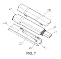
- FIG. 7 is a schematic structural view of each separated part of the electronic device in FIG. 6 when the USB connector is in the released state.
- the present invention is directed to an electronic device with a USB connector.
- an embodiment of the present invention is described in detail with reference to the accompanying drawings.
- the embodiment of the present invention provides an electronic device with a USB connector, which, as shown in FIGS. 2 to 7 , includes an outer housing 21 , an intermediate housing 22 located inside the outer housing 21 and moveable relative to the outer housing 21 , and a circuit board (not shown) inside the intermediate housing 22 .
- the USB connector 23 is disposed on the intermediate housing 22 and electrically connected to the circuit board.
- a USB connector through hole 24 is configured on the outer housing 21 at a position corresponding to the USB connector 23 .
- the electronic device further includes an elastic apparatus 25 disposed in a moving direction of the intermediate housing 22 , and an intermediate housing movement positioning apparatus 26 .
- USB connector 23 is connected to the circuit board, and the electronic device realizes data communication with devices such as computers through the USB connector 23 .
- the USB connector 23 on the intermediate housing 22 is received in the outer housing 21 , and the USB connector 23 is in a received state.
- the intermediate housing 22 is pushed to move relative to the outer housing 21 , so that the USB connector 23 is released from the USB connector through hole 24 on the outer housing 21 .
- the USB connector 23 is in a released state, and the electronic device can be used.
- the USB connector 23 on the intermediate housing 22 under the combined effect of the elastic apparatus 25 and the intermediate housing movement positioning apparatus 26 , may switch between the received state and released state, so that the embodiment of the present invention does not need to use the USB cap, thereby avoiding the problem in the conventional art that the USB cap may easily get lost.
- the USB connector 23 on the intermediate housing 22 under the combined effect of the elastic apparatus 25 and the intermediate housing movement positioning apparatus 26 , may switch between the received state and released state.
- the functions of the two apparatus are illustrated in detail as follows.
- an elastic force of the elastic apparatus 25 enables the USB connector 23 on the intermediate housing 22 to be received in the outer housing 21 .
- the intermediate housing 22 is pushed to release the USB connector 23 out of the outer housing 21 .
- the movement of the intermediate housing 22 causes a continuous deformation of the elastic apparatus 25
- the intermediate housing movement positioning apparatus 26 is triggered to generate a positioning effect.
- the intermediate housing 22 and the outer housing 21 remain static, and the USB connector 23 on the intermediate housing 22 remains in the released state.
- the intermediate housing movement positioning apparatus 26 is triggered again to disenable the positioning effect. Therefore, under the deformation force of the elastic apparatus 25 , the electronic device recovers to the initial state, and the USB connector 23 returns to the received state.
- the elastic apparatus 25 in this embodiment includes a spring located inside the outer housing and wound around the USB connector 23 .
- the spring keeps exerting an elastic force on the intermediate housing 22 and the outer housing 21 , so as to ensure a certain distance there-between.
- the outer housing 21 and the intermediate housing 22 are directly utilized to support two ends of the spring. It is easy to realize the setting manner, and the spring is located in an idle space surrounding the USB connector 23 , so that no additional space will be occupied.
- the elastic apparatus 25 may also be disposed at a side of the intermediate housing 22 , and the spring may also be replaced with other elastic components (such as a rubber band).
- other implementation manners also have the same principle and similar structure, and thus are not repeated herein one by one.
- the intermediate housing movement positioning apparatus 26 in this embodiment includes a pendulum spring 27 and a pendulum spring chute 28 .
- One end of the pendulum spring 27 is fixed on an external surface of the intermediate housing 22 , and the other end thereof has a folding arm 29 disposed thereon and located within the pendulum spring chute 28 .
- the pendulum spring chute 28 is located on an internal surface of the outer housing 21 , and the pendulum spring chute 28 is heart-shaped.
- the heart-shaped pendulum spring chute 28 has a pendulum spring propelling chute 281 at one side, and a pendulum spring receding chute 282 at the other side.
- the outer housing 21 is divided into an upper housing 211 and a lower housing 212 . Furthermore, in order to facilitate the processing of the outer housing 21 , the outer housing 21 may also employ a structure of combined upper and lower housings. In this embodiment, the pendulum spring chute 28 is located on the internal surface of the upper housing 211 .
- the USB connector 23 of the electronic device is in a received state.
- the folding arm 29 at the end of the pendulum spring 27 is located at a lower end point A of the pendulum spring chute 28 .
- the intermediate housing 22 When the electronic device is in use, the intermediate housing 22 is pushed upward to release the USB connector 23 out of the outer housing 21 , and then the pushing is stopped. During this process, the intermediate housing 22 firstly drives the pendulum spring 27 to move upward, and the folding arm 29 moves from the lower end point A to a right upper end point B of the pendulum spring chute 28 along the pendulum spring propelling chute 281 , and then the pushing is stopped. Under the effect of the elastic force of the elastic apparatus 25 , the intermediate housing 22 further drives the pendulum spring 27 to move downward, and the folding arm 29 moves from the right upper end point B to a middle end point C along the pendulum spring chute 28 . At the point C, since the folding arm 29 is blocked by the pendulum spring chute 28 , the pendulum spring 27 cannot go on moving downward, and the intermediate housing 22 stops moving correspondingly. At this time, the USB connector 23 of the electronic device remains in the released state.
- the intermediate housing 22 When the electronic device is not in use, the intermediate housing 22 is also pushed upward first, and then the pushing is stopped. During this process, the intermediate housing 22 firstly drives the pendulum spring 27 to move upward, and the folding arm 29 moves from the point C to a left upper end point D of the pendulum spring chute 28 , and then the pushing is stopped. Under the effect of the elastic force of the elastic apparatus 25 , the intermediate housing 22 further drives the pendulum spring 27 to move downward, the folding arm 29 moves from the point D back to the point A of the pendulum spring chute 28 , and the USB connector 23 of the electronic device returns to the received state.
- the pendulum spring chute 28 is heart-shaped, and has a pendulum spring propelling chute 281 at its right side and a pendulum spring receding chute 282 at its left side.
- the folding arm 29 automatically enters the pendulum spring propelling chute 281 from the initial position of the point A, then enters the pendulum spring receding chute 282 from the pendulum spring propelling chute 281 , and finally returns to the initial position of the point A from the pendulum spring receding chute 282 .
- FIG. 4 A preferred design of the heart-shaped pendulum spring chute 28 is shown in FIG. 4 .
- the angle between the line from point A to point B, and the vertical line through point A is larger than the angle between the line from point A to point D, and the vertical line through point A.
- the angle between the line from point C to point B, and the vertical line through point C is larger than the angle between the line from point C to point D, and the vertical line through point C. It is preferred that point A and point C is not in the same vertical line.
- the pendulum spring chute 28 is half-heart-shaped, for example, only the pendulum spring propelling chute 281 or the pendulum spring receding chute 282 exists. In another embodiment, the pendulum spring chute 28 is full-heart-shaped, the pendulum spring propelling chute 281 and the pendulum spring receding chute 282 is symmetrical.
- a pendulum slot 30 is configured on the intermediate housing 22 , and the pendulum spring 27 is located within the pendulum slot 30 .
- the folding arm 29 at the end of the pendulum spring 27 moves back and forth in the pendulum spring chute 28 , the body of the pendulum spring 27 swings left to right in the pendulum slot 30 , so that the space occupied by the body of the pendulum spring 27 is saved.
- the process of fixing one end of the pendulum spring 27 on the intermediate housing 22 may be realized through the following manner.
- a pillar 31 is configured at a lower end of the pendulum slot 30 , and the end of the pendulum spring 27 is closely clipped between the pillar 31 and the pendulum slot 30 .
- the pendulum spring 27 may also be fixed by screws or by other commonly used fixing methods, and the details thereof are not described herein again.
- the pendulum spring 27 thereof is disposed on the intermediate housing 22
- the pendulum spring chute 28 is disposed on the outer housing 21 .
- the positions of the pendulum spring 27 and the pendulum spring chute 28 can be exchanged, and other technical features remain the same. That is, the following technical solution is adopted.
- the intermediate housing movement positioning apparatus includes a pendulum spring and a pendulum spring chute.
- One end of the pendulum spring is fixed on an internal surface of the outer housing, and the other end thereof has a folding arm disposed thereon and located within the pendulum spring chute.
- the pendulum spring chute is located on an external surface of the intermediate housing, and the pendulum spring chute is heart-shaped.
- the heart-shaped pendulum spring chute has a pendulum spring propelling chute at one side, and a pendulum spring receding chute at the other side.
- the position of the pendulum slot also needs to be changed correspondingly, that is, the pendulum slot is configured on the outer housing, and the pendulum spring is located within the pendulum slot.
- the intermediate housing movement positioning apparatus also has other implementing manners.
- a plurality of jacks is configured on the intermediate housing, and a pin is disposed on the outer housing.
- the intermediate housing is pushed to move to a certain position relative to the outer housing, and then the pin is pressed, so that the positions of the intermediate housing and the outer housing are fixed.
- the pin is loosened, and the intermediate housing automatically recovers to the initial position under the effect of the elastic apparatus. In this manner, the user is required not only to push the intermediate housing, but also to press the pin, so that the operating process is a little bit complicated.
- the intermediate housing movement positioning apparatus is not limited to the aforementioned three embodiments, but other circumstances may not be described herein one by one.
- the pendulum spring chute 28 may also include a common chute 283 , which is located at a lower part of the pendulum spring chute 28 , and communicated with the pendulum spring propelling chute 281 and the pendulum spring receding chute 282 .
- the folding arm 29 is located at a lower end point O of the common chute 283 .
- a moving route of the folding arm 29 at the end of the pendulum spring 27 is OABC; and when the electronic device is not in use, a moving route of the folding arm 29 is CDAO.
- the common chute 283 may elongate the chute and reduce the gradient, so that the intermediate housing 22 moves more steadily.
- the embodiment of the present invention is applicable to electronic devices with a USB connector such as a wireless USB Modem or a USB flash drive.
Abstract
Description
Claims (11)
Priority Applications (2)
| Application Number | Priority Date | Filing Date | Title |
|---|---|---|---|
| JP2012502439A JP5392522B2 (en) | 2009-03-31 | 2010-03-31 | Electronic device having a USB connector |
| PCT/CN2010/071460 WO2010111950A1 (en) | 2009-03-31 | 2010-03-31 | Electronic equipment with usb connector |
Applications Claiming Priority (3)
| Application Number | Priority Date | Filing Date | Title |
|---|---|---|---|
| CN200920009451U | 2009-03-31 | ||
| CN2009200094516U CN201397897Y (en) | 2009-03-31 | 2009-03-31 | Electronic device with USB adapter |
| CN200920009451.6 | 2009-03-31 |
Publications (2)
| Publication Number | Publication Date |
|---|---|
| US20100248510A1 US20100248510A1 (en) | 2010-09-30 |
| US8043101B2 true US8043101B2 (en) | 2011-10-25 |
Family
ID=41620425
Family Applications (1)
| Application Number | Title | Priority Date | Filing Date |
|---|---|---|---|
| US12/686,513 Active US8043101B2 (en) | 2009-03-31 | 2010-01-13 | Electronic device with USB connector |
Country Status (6)
| Country | Link |
|---|---|
| US (1) | US8043101B2 (en) |
| EP (1) | EP2237379B1 (en) |
| JP (1) | JP5392522B2 (en) |
| CN (1) | CN201397897Y (en) |
| ES (1) | ES2526363T3 (en) |
| WO (1) | WO2010111950A1 (en) |
Cited By (6)
| Publication number | Priority date | Publication date | Assignee | Title |
|---|---|---|---|---|
| US20100136808A1 (en) * | 2007-03-27 | 2010-06-03 | Van-System S.R.L. | Electrical Connector |
| US20120220150A1 (en) * | 2010-07-09 | 2012-08-30 | Powertech Industrial Co., Ltd. | Retractable power plug |
| US20120225569A1 (en) * | 2009-11-11 | 2012-09-06 | Huawei Device Co.,Ltd. | Electronic apparatus with plug |
| US20130100617A1 (en) * | 2011-02-25 | 2013-04-25 | Huawei Device Co., Ltd. | Connector and Wireless Modem |
| US20140204524A1 (en) * | 2013-01-22 | 2014-07-24 | Phison Electronics Corp. | Storage device |
| US9337562B1 (en) * | 2014-12-10 | 2016-05-10 | Adata Technology Co., Ltd. | Pressable portable storage device |
Families Citing this family (10)
| Publication number | Priority date | Publication date | Assignee | Title |
|---|---|---|---|---|
| CN201397897Y (en) * | 2009-03-31 | 2010-02-03 | 深圳华为通信技术有限公司 | Electronic device with USB adapter |
| CN102347056A (en) * | 2011-06-27 | 2012-02-08 | 苏州天擎电子通讯有限公司 | Novel structure of USB (Universal Serial Bus) flash drive |
| USD673963S1 (en) | 2011-10-19 | 2013-01-08 | MIMOCO, Inc. | USB drive |
| USD673962S1 (en) | 2011-10-24 | 2013-01-08 | MIMOCO, Inc. | USB drive and card reader with body |
| CN102625616B (en) * | 2012-04-11 | 2015-02-11 | 合肥宝龙达信息技术有限公司 | Repeated pushing reset U disk |
| DE202013000706U1 (en) | 2013-01-16 | 2013-02-04 | Hohenstein Vorrichtungsbau Und Spannsysteme Gmbh | Information module with product data |
| USD759027S1 (en) * | 2014-12-26 | 2016-06-14 | Intel Corporation | PC on a stick |
| TWI552454B (en) * | 2015-03-25 | 2016-10-01 | 威剛科技股份有限公司 | Pressable portable storage device |
| USD860935S1 (en) * | 2017-10-18 | 2019-09-24 | Parker Rosen | Wearable charging device |
| US11108185B2 (en) * | 2019-08-29 | 2021-08-31 | Rockwell Automation Switzerland Gmbh | Busbar adapter with shielded terminals |
Citations (17)
| Publication number | Priority date | Publication date | Assignee | Title |
|---|---|---|---|---|
| US6579108B1 (en) * | 2001-10-17 | 2003-06-17 | 3Com Corporation | Retractable jack |
| US20040077216A1 (en) | 2002-10-18 | 2004-04-22 | Aiptek International Inc. | USB connector structure with protection means |
| US20040090751A1 (en) | 2002-11-08 | 2004-05-13 | Choi Dae Seon | Portable USB storage device |
| EP1557907A2 (en) | 2004-01-21 | 2005-07-27 | h & m gutberlet gmbh | Memory apparatus and writing device having such an apparatus |
| CN2735508Y (en) | 2004-08-02 | 2005-10-19 | 东莞市华鹰电子有限公司 | A retractable U-disk |
| US7104814B1 (en) | 2004-12-31 | 2006-09-12 | Inventec Multimedia Telecom Corporation | Electronic device with sheath structure |
| EP1703782A1 (en) | 2005-03-15 | 2006-09-20 | Imation Ireland Limited | Mechanical spring component for use in memory device |
| US20060258196A1 (en) | 2005-05-13 | 2006-11-16 | Jing Chen | Electronic device having a sliding cap |
| CN2930209Y (en) | 2006-06-02 | 2007-08-01 | 乐清市三星电脑通讯设备有限公司 | Telescopic U-disc metal casing |
| US7307849B2 (en) * | 2005-12-07 | 2007-12-11 | Silicon Power Computer & Communications Inc. | Flash memory disk |
| US20080076280A1 (en) | 2006-09-27 | 2008-03-27 | Asustek Computer Inc. | Portable Storage Device |
| CN101295825A (en) | 2007-04-24 | 2008-10-29 | 富士康(昆山)电脑接插件有限公司 | Electronic card connector |
| CN201197231Y (en) | 2008-05-20 | 2009-02-18 | 余晓峰 | Movable memory with telescopic USB plug |
| US20090177835A1 (en) * | 2004-01-20 | 2009-07-09 | Super Talent Electronics, Inc. | Flash Drive With Spring-Loaded Retractable Connector |
| US20090275224A1 (en) * | 2007-06-28 | 2009-11-05 | Super Talent Electronics, Inc. | Lipstick-Type USB Device |
| US7632113B2 (en) * | 2003-11-17 | 2009-12-15 | Dpd Patent Trust Ltd. | Retractable USB stick |
| CN201397897Y (en) | 2009-03-31 | 2010-02-03 | 深圳华为通信技术有限公司 | Electronic device with USB adapter |
Family Cites Families (1)
| Publication number | Priority date | Publication date | Assignee | Title |
|---|---|---|---|---|
| JP3878656B1 (en) * | 2005-03-31 | 2007-02-07 | 知広 阿部 | Case storage medium |
-
2009
- 2009-03-31 CN CN2009200094516U patent/CN201397897Y/en not_active Expired - Lifetime
-
2010
- 2010-01-13 US US12/686,513 patent/US8043101B2/en active Active
- 2010-01-20 ES ES10151140.0T patent/ES2526363T3/en active Active
- 2010-01-20 EP EP10151140.0A patent/EP2237379B1/en active Active
- 2010-03-31 JP JP2012502439A patent/JP5392522B2/en active Active
- 2010-03-31 WO PCT/CN2010/071460 patent/WO2010111950A1/en active Application Filing
Patent Citations (23)
| Publication number | Priority date | Publication date | Assignee | Title |
|---|---|---|---|---|
| US6579108B1 (en) * | 2001-10-17 | 2003-06-17 | 3Com Corporation | Retractable jack |
| US20040077216A1 (en) | 2002-10-18 | 2004-04-22 | Aiptek International Inc. | USB connector structure with protection means |
| US6808400B2 (en) * | 2002-10-18 | 2004-10-26 | Aiptek International Inc. | USB connector structure with protection means |
| US20040090751A1 (en) | 2002-11-08 | 2004-05-13 | Choi Dae Seon | Portable USB storage device |
| US7632113B2 (en) * | 2003-11-17 | 2009-12-15 | Dpd Patent Trust Ltd. | Retractable USB stick |
| US20090177835A1 (en) * | 2004-01-20 | 2009-07-09 | Super Talent Electronics, Inc. | Flash Drive With Spring-Loaded Retractable Connector |
| EP1557907A2 (en) | 2004-01-21 | 2005-07-27 | h & m gutberlet gmbh | Memory apparatus and writing device having such an apparatus |
| CN2735508Y (en) | 2004-08-02 | 2005-10-19 | 东莞市华鹰电子有限公司 | A retractable U-disk |
| US7104814B1 (en) | 2004-12-31 | 2006-09-12 | Inventec Multimedia Telecom Corporation | Electronic device with sheath structure |
| US20060205252A1 (en) * | 2004-12-31 | 2006-09-14 | Inventec Multimedia & Telecom Corporation | Electronic device with sheath structure |
| US20070015407A1 (en) * | 2005-03-15 | 2007-01-18 | Memorex International, Inc. | Mechanical spring component for use in memory device |
| EP1703782A1 (en) | 2005-03-15 | 2006-09-20 | Imation Ireland Limited | Mechanical spring component for use in memory device |
| US20060258196A1 (en) | 2005-05-13 | 2006-11-16 | Jing Chen | Electronic device having a sliding cap |
| US7307849B2 (en) * | 2005-12-07 | 2007-12-11 | Silicon Power Computer & Communications Inc. | Flash memory disk |
| CN2930209Y (en) | 2006-06-02 | 2007-08-01 | 乐清市三星电脑通讯设备有限公司 | Telescopic U-disc metal casing |
| US20080076280A1 (en) | 2006-09-27 | 2008-03-27 | Asustek Computer Inc. | Portable Storage Device |
| CN101295825A (en) | 2007-04-24 | 2008-10-29 | 富士康(昆山)电脑接插件有限公司 | Electronic card connector |
| US20090275224A1 (en) * | 2007-06-28 | 2009-11-05 | Super Talent Electronics, Inc. | Lipstick-Type USB Device |
| US7850468B2 (en) * | 2007-06-28 | 2010-12-14 | Super Talent Electronics, Inc. | Lipstick-type USB device |
| CN201197231Y (en) | 2008-05-20 | 2009-02-18 | 余晓峰 | Movable memory with telescopic USB plug |
| CN201397897Y (en) | 2009-03-31 | 2010-02-03 | 深圳华为通信技术有限公司 | Electronic device with USB adapter |
| US20100248510A1 (en) * | 2009-03-31 | 2010-09-30 | Huawei Device Co., Ltd. | Electronic device with usb connector |
| WO2010111950A1 (en) | 2009-03-31 | 2010-10-07 | 华为终端有限公司 | Electronic equipment with usb connector |
Non-Patent Citations (1)
| Title |
|---|
| Extended European Search Report in corresponding European Application No. 10151140.0 (Apr. 22, 2010). |
Cited By (9)
| Publication number | Priority date | Publication date | Assignee | Title |
|---|---|---|---|---|
| US20100136808A1 (en) * | 2007-03-27 | 2010-06-03 | Van-System S.R.L. | Electrical Connector |
| US20120225569A1 (en) * | 2009-11-11 | 2012-09-06 | Huawei Device Co.,Ltd. | Electronic apparatus with plug |
| US8500466B2 (en) * | 2009-11-11 | 2013-08-06 | Huawei Device Co., Ltd. | Electronic apparatus with plug |
| US20120220150A1 (en) * | 2010-07-09 | 2012-08-30 | Powertech Industrial Co., Ltd. | Retractable power plug |
| US8366462B2 (en) * | 2010-07-09 | 2013-02-05 | Powertech Industrial Co., Ltd. | Retractable power plug |
| US20130100617A1 (en) * | 2011-02-25 | 2013-04-25 | Huawei Device Co., Ltd. | Connector and Wireless Modem |
| US20140204524A1 (en) * | 2013-01-22 | 2014-07-24 | Phison Electronics Corp. | Storage device |
| US9585272B2 (en) * | 2013-01-22 | 2017-02-28 | Phison Electronics Corp. | Storage device |
| US9337562B1 (en) * | 2014-12-10 | 2016-05-10 | Adata Technology Co., Ltd. | Pressable portable storage device |
Also Published As
| Publication number | Publication date |
|---|---|
| JP5392522B2 (en) | 2014-01-22 |
| US20100248510A1 (en) | 2010-09-30 |
| ES2526363T3 (en) | 2015-01-09 |
| JP2012522338A (en) | 2012-09-20 |
| CN201397897Y (en) | 2010-02-03 |
| WO2010111950A1 (en) | 2010-10-07 |
| EP2237379A1 (en) | 2010-10-06 |
| EP2237379B1 (en) | 2014-10-08 |
Similar Documents
| Publication | Publication Date | Title |
|---|---|---|
| US8043101B2 (en) | Electronic device with USB connector | |
| CN107241468B (en) | Display device and mobile terminal | |
| US9223356B2 (en) | Electronic device | |
| US8657619B2 (en) | Fixing mechanism for fixing a board and electronic device therewith | |
| US8622646B2 (en) | Electronic device with slot cover ejection mechanism | |
| CN102606855B (en) | Base and use the electronic equipment assembly of this base | |
| US9455759B2 (en) | Protection device capable of rotatably supporting a portable electronic device | |
| US7713075B2 (en) | Protrudable connector structure for electronic device | |
| US8725210B2 (en) | Attachable assembly | |
| US8976522B2 (en) | Portable electronic device and docking device thereof | |
| US20160240945A1 (en) | Button-type connector module and electronic device using the same | |
| US20140170871A1 (en) | Electronic device with rotable connector | |
| US9280178B2 (en) | Portable electronic apparatus and expanding platform thereof | |
| CN108093681A (en) | A kind of pedestal, mobile terminal, earphone and earphone base | |
| CN209748673U (en) | Camera module and electronic equipment | |
| CN105827773A (en) | Portable electronic device and quick button thereof integrated with camera module | |
| US9541956B2 (en) | Supporting structure and docking station using the same | |
| US8873229B2 (en) | Electronic device having card holder | |
| CN203734721U (en) | Multifunctional gamepad | |
| CN110392140A (en) | Electronic equipment | |
| US9304554B2 (en) | Signal transmission device | |
| CN109962995B (en) | Functional assembly, electronic device and control method thereof | |
| CN103365340A (en) | Docking station and electronic device | |
| CN2884798Y (en) | Buckling means | |
| CN212460436U (en) | Electronic device |
Legal Events
| Date | Code | Title | Description |
|---|---|---|---|
| AS | Assignment |
Owner name: HUAWEI DEVICE CO., LTD., CHINA Free format text: ASSIGNMENT OF ASSIGNORS INTEREST;ASSIGNORS:ZHANG, BIN;HUANG, YANZHU;LI, JIE;AND OTHERS;REEL/FRAME:023772/0102 Effective date: 20100111 |
|
| STCF | Information on status: patent grant |
Free format text: PATENTED CASE |
|
| FPAY | Fee payment |
Year of fee payment: 4 |
|
| AS | Assignment |
Owner name: HUAWEI DEVICE (SHENZHEN) CO., LTD., CHINA Free format text: CHANGE OF NAME;ASSIGNOR:HUAWEI DEVICE CO.,LTD.;REEL/FRAME:046340/0590 Effective date: 20180518 |
|
| AS | Assignment |
Owner name: HUAWEI DEVICE CO., LTD., CHINA Free format text: ASSIGNMENT OF ASSIGNORS INTEREST;ASSIGNOR:HUAWEI DEVICE (SHENZHEN) CO., LTD.;REEL/FRAME:047603/0039 Effective date: 20181119 |
|
| MAFP | Maintenance fee payment |
Free format text: PAYMENT OF MAINTENANCE FEE, 8TH YEAR, LARGE ENTITY (ORIGINAL EVENT CODE: M1552); ENTITY STATUS OF PATENT OWNER: LARGE ENTITY Year of fee payment: 8 |
|
| MAFP | Maintenance fee payment |
Free format text: PAYMENT OF MAINTENANCE FEE, 12TH YEAR, LARGE ENTITY (ORIGINAL EVENT CODE: M1553); ENTITY STATUS OF PATENT OWNER: LARGE ENTITY Year of fee payment: 12 |