US8043381B2 - Minimally invasive interbody device and method - Google Patents
Minimally invasive interbody device and method Download PDFInfo
- Publication number
- US8043381B2 US8043381B2 US11/926,975 US92697507A US8043381B2 US 8043381 B2 US8043381 B2 US 8043381B2 US 92697507 A US92697507 A US 92697507A US 8043381 B2 US8043381 B2 US 8043381B2
- Authority
- US
- United States
- Prior art keywords
- coupler
- fill tube
- filler material
- access point
- cavity
- Prior art date
- Legal status (The legal status is an assumption and is not a legal conclusion. Google has not performed a legal analysis and makes no representation as to the accuracy of the status listed.)
- Expired - Fee Related, expires
Links
Images


Classifications
-
- A—HUMAN NECESSITIES
- A61—MEDICAL OR VETERINARY SCIENCE; HYGIENE
- A61F—FILTERS IMPLANTABLE INTO BLOOD VESSELS; PROSTHESES; DEVICES PROVIDING PATENCY TO, OR PREVENTING COLLAPSING OF, TUBULAR STRUCTURES OF THE BODY, e.g. STENTS; ORTHOPAEDIC, NURSING OR CONTRACEPTIVE DEVICES; FOMENTATION; TREATMENT OR PROTECTION OF EYES OR EARS; BANDAGES, DRESSINGS OR ABSORBENT PADS; FIRST-AID KITS
- A61F2/00—Filters implantable into blood vessels; Prostheses, i.e. artificial substitutes or replacements for parts of the body; Appliances for connecting them with the body; Devices providing patency to, or preventing collapsing of, tubular structures of the body, e.g. stents
- A61F2/02—Prostheses implantable into the body
- A61F2/30—Joints
- A61F2/44—Joints for the spine, e.g. vertebrae, spinal discs
- A61F2/441—Joints for the spine, e.g. vertebrae, spinal discs made of inflatable pockets or chambers filled with fluid, e.g. with hydrogel
-
- A—HUMAN NECESSITIES
- A61—MEDICAL OR VETERINARY SCIENCE; HYGIENE
- A61F—FILTERS IMPLANTABLE INTO BLOOD VESSELS; PROSTHESES; DEVICES PROVIDING PATENCY TO, OR PREVENTING COLLAPSING OF, TUBULAR STRUCTURES OF THE BODY, e.g. STENTS; ORTHOPAEDIC, NURSING OR CONTRACEPTIVE DEVICES; FOMENTATION; TREATMENT OR PROTECTION OF EYES OR EARS; BANDAGES, DRESSINGS OR ABSORBENT PADS; FIRST-AID KITS
- A61F2/00—Filters implantable into blood vessels; Prostheses, i.e. artificial substitutes or replacements for parts of the body; Appliances for connecting them with the body; Devices providing patency to, or preventing collapsing of, tubular structures of the body, e.g. stents
- A61F2/02—Prostheses implantable into the body
- A61F2/30—Joints
- A61F2/46—Special tools or methods for implanting or extracting artificial joints, accessories, bone grafts or substitutes, or particular adaptations therefor
- A61F2/4603—Special tools or methods for implanting or extracting artificial joints, accessories, bone grafts or substitutes, or particular adaptations therefor for insertion or extraction of endoprosthetic joints or of accessories thereof
- A61F2/4611—Special tools or methods for implanting or extracting artificial joints, accessories, bone grafts or substitutes, or particular adaptations therefor for insertion or extraction of endoprosthetic joints or of accessories thereof of spinal prostheses
-
- A—HUMAN NECESSITIES
- A61—MEDICAL OR VETERINARY SCIENCE; HYGIENE
- A61F—FILTERS IMPLANTABLE INTO BLOOD VESSELS; PROSTHESES; DEVICES PROVIDING PATENCY TO, OR PREVENTING COLLAPSING OF, TUBULAR STRUCTURES OF THE BODY, e.g. STENTS; ORTHOPAEDIC, NURSING OR CONTRACEPTIVE DEVICES; FOMENTATION; TREATMENT OR PROTECTION OF EYES OR EARS; BANDAGES, DRESSINGS OR ABSORBENT PADS; FIRST-AID KITS
- A61F2/00—Filters implantable into blood vessels; Prostheses, i.e. artificial substitutes or replacements for parts of the body; Appliances for connecting them with the body; Devices providing patency to, or preventing collapsing of, tubular structures of the body, e.g. stents
- A61F2/02—Prostheses implantable into the body
- A61F2/30—Joints
- A61F2002/30001—Additional features of subject-matter classified in A61F2/28, A61F2/30 and subgroups thereof
- A61F2002/30108—Shapes
- A61F2002/30199—Three-dimensional shapes
- A61F2002/302—Three-dimensional shapes toroidal, e.g. rings
-
- A—HUMAN NECESSITIES
- A61—MEDICAL OR VETERINARY SCIENCE; HYGIENE
- A61F—FILTERS IMPLANTABLE INTO BLOOD VESSELS; PROSTHESES; DEVICES PROVIDING PATENCY TO, OR PREVENTING COLLAPSING OF, TUBULAR STRUCTURES OF THE BODY, e.g. STENTS; ORTHOPAEDIC, NURSING OR CONTRACEPTIVE DEVICES; FOMENTATION; TREATMENT OR PROTECTION OF EYES OR EARS; BANDAGES, DRESSINGS OR ABSORBENT PADS; FIRST-AID KITS
- A61F2/00—Filters implantable into blood vessels; Prostheses, i.e. artificial substitutes or replacements for parts of the body; Appliances for connecting them with the body; Devices providing patency to, or preventing collapsing of, tubular structures of the body, e.g. stents
- A61F2/02—Prostheses implantable into the body
- A61F2/30—Joints
- A61F2002/30001—Additional features of subject-matter classified in A61F2/28, A61F2/30 and subgroups thereof
- A61F2002/30316—The prosthesis having different structural features at different locations within the same prosthesis; Connections between prosthetic parts; Special structural features of bone or joint prostheses not otherwise provided for
- A61F2002/30535—Special structural features of bone or joint prostheses not otherwise provided for
- A61F2002/30581—Special structural features of bone or joint prostheses not otherwise provided for having a pocket filled with fluid, e.g. liquid
- A61F2002/30586—Special structural features of bone or joint prostheses not otherwise provided for having a pocket filled with fluid, e.g. liquid having two or more inflatable pockets or chambers
-
- A—HUMAN NECESSITIES
- A61—MEDICAL OR VETERINARY SCIENCE; HYGIENE
- A61F—FILTERS IMPLANTABLE INTO BLOOD VESSELS; PROSTHESES; DEVICES PROVIDING PATENCY TO, OR PREVENTING COLLAPSING OF, TUBULAR STRUCTURES OF THE BODY, e.g. STENTS; ORTHOPAEDIC, NURSING OR CONTRACEPTIVE DEVICES; FOMENTATION; TREATMENT OR PROTECTION OF EYES OR EARS; BANDAGES, DRESSINGS OR ABSORBENT PADS; FIRST-AID KITS
- A61F2/00—Filters implantable into blood vessels; Prostheses, i.e. artificial substitutes or replacements for parts of the body; Appliances for connecting them with the body; Devices providing patency to, or preventing collapsing of, tubular structures of the body, e.g. stents
- A61F2/02—Prostheses implantable into the body
- A61F2/30—Joints
- A61F2002/30001—Additional features of subject-matter classified in A61F2/28, A61F2/30 and subgroups thereof
- A61F2002/30316—The prosthesis having different structural features at different locations within the same prosthesis; Connections between prosthetic parts; Special structural features of bone or joint prostheses not otherwise provided for
- A61F2002/30535—Special structural features of bone or joint prostheses not otherwise provided for
- A61F2002/30593—Special structural features of bone or joint prostheses not otherwise provided for hollow
-
- A—HUMAN NECESSITIES
- A61—MEDICAL OR VETERINARY SCIENCE; HYGIENE
- A61F—FILTERS IMPLANTABLE INTO BLOOD VESSELS; PROSTHESES; DEVICES PROVIDING PATENCY TO, OR PREVENTING COLLAPSING OF, TUBULAR STRUCTURES OF THE BODY, e.g. STENTS; ORTHOPAEDIC, NURSING OR CONTRACEPTIVE DEVICES; FOMENTATION; TREATMENT OR PROTECTION OF EYES OR EARS; BANDAGES, DRESSINGS OR ABSORBENT PADS; FIRST-AID KITS
- A61F2/00—Filters implantable into blood vessels; Prostheses, i.e. artificial substitutes or replacements for parts of the body; Appliances for connecting them with the body; Devices providing patency to, or preventing collapsing of, tubular structures of the body, e.g. stents
- A61F2/02—Prostheses implantable into the body
- A61F2/30—Joints
- A61F2/30767—Special external or bone-contacting surface, e.g. coating for improving bone ingrowth
- A61F2/30771—Special external or bone-contacting surface, e.g. coating for improving bone ingrowth applied in original prostheses, e.g. holes or grooves
- A61F2002/30878—Special external or bone-contacting surface, e.g. coating for improving bone ingrowth applied in original prostheses, e.g. holes or grooves with non-sharp protrusions, for instance contacting the bone for anchoring, e.g. keels, pegs, pins, posts, shanks, stems, struts
- A61F2002/30884—Fins or wings, e.g. longitudinal wings for preventing rotation within the bone cavity
-
- A—HUMAN NECESSITIES
- A61—MEDICAL OR VETERINARY SCIENCE; HYGIENE
- A61F—FILTERS IMPLANTABLE INTO BLOOD VESSELS; PROSTHESES; DEVICES PROVIDING PATENCY TO, OR PREVENTING COLLAPSING OF, TUBULAR STRUCTURES OF THE BODY, e.g. STENTS; ORTHOPAEDIC, NURSING OR CONTRACEPTIVE DEVICES; FOMENTATION; TREATMENT OR PROTECTION OF EYES OR EARS; BANDAGES, DRESSINGS OR ABSORBENT PADS; FIRST-AID KITS
- A61F2230/00—Geometry of prostheses classified in groups A61F2/00 - A61F2/26 or A61F2/82 or A61F9/00 or A61F11/00 or subgroups thereof
- A61F2230/0063—Three-dimensional shapes
- A61F2230/0065—Three-dimensional shapes toroidal, e.g. ring-shaped, doughnut-shaped
Definitions
- This invention relates to orthopedic implants, and, more particularly, to interbody spinal devices.
- a spine includes a series of joints or motion segments.
- the components of each motion segment include two adjacent vertebrae, their apophyseal joints, an intervertebral disc, and connecting ligamentous tissue.
- Each motion segment is capable of flexion, extension, lateral bending, and translation.
- Each component of the motion segment contributes to these capabilities and to the mechanical stability of the spine.
- the intervertebral disc is one component that facilitates spine motion by allowing slight relative movement between adjacent intervertebral discs as well as holding the vertebrae together.
- the discs comprise an outer annulus fibrosus which surrounds and contains a nucleus pulposus.
- the nucleus acts as a shock absorber and a spacer to separate adjacent vertebra.
- the motion segments, including the discs collectively enable the familiar kinematics of the spinal column.
- degeneration of the disc can cause great and sometimes debilitating pain.
- radicular pain in the lower extremities is often a symptom of a herniated disc.
- a herniated disc is characterized by rupture of or tear in the annulus fibrosus which permits a portion of the nucleus to extrude therefrom. If the nucleus extrudes in proximity to the numerous nerves surrounding the spine, the pressure, or the mere contact, of the nucleus on the nerves may cause severe pain.
- axial pain is often a symptom of degenerative disc disease.
- Degenerative disc disease is generally associated with dehydration of the nucleus that occurs with age. When the nucleus dehydrates, it loses its ability to absorb shock, which may lead to axial pain.
- Treatment methods for repair of disc disorders include spinal fusion.
- spinal fusion procedure requires resection of a portion of the disc.
- the procedure for removing a portion of the disc is known as a discectomy.
- another material or device is inserted into the space created to stabilize the spinal column.
- devices available for insertion into the disc space.
- one fusion procedure includes placing a cage between and in contact with the vertebra and packing the cage with graft material.
- the graft material may bond with the endplates of the adjacent vertebra thus fusing the vertebra together.
- these types of devices require significant retraction of tissue to allow the surgeon sufficient access to the disc and to insert the device into the corresponding disc space. Consequently, patient recovery time may be significant simply because of the invasiveness of these procedures.
- the present invention provides an interbody device adapted for insertion between adjacent vertebrae in a spine.
- the device comprises a member having a flexible wall surrounding an internal volume and a coupler.
- the member is adapted to expand when filled with a first filler material to form an interior cavity.
- the coupler is secured to the flexible wall.
- the coupler has a first access point, a second access point, a first coupler side hole, and an optional second coupler side hole.
- the first and second access points are adapted to removably receive one or more fill tubes.
- the fill tubes cooperate with the first and optional second coupler side holes to direct the first filler material into the internal volume and a second filler material into the interior cavity.
- an orthopedic system is provided.
- the orthopedic system is adapted for insertion between adjacent vertebrae in a spine.
- the system comprises a member having a flexible wall surrounding an internal volume and a coupler secured to the flexible wall.
- the member is adapted to expand when filled with a first filler material to form an interior cavity.
- the coupler has a first access point, a second access point, a first coupler side hole, and an optional second coupler side hole adapted to removably receive one or more fill tubes.
- the fill tubes cooperate with the first and optional second coupler side holes to direct the first filler material into the internal volume and that cooperate to direct a second filler material into the interior cavity.
- a member fill tube defines a first passage and is adapted for removable cooperation with the coupler via the first access point.
- an opening at a distal end of the member fill tube is in fluid communication with the internal volume via the first passage, the first coupler side hole, and the optional second coupler side hole.
- a cavity fill tube defines a second passage. The cavity fill tube is adapted for removable cooperation with the coupler via the first access point and the second access point. When the cavity fill tube is inserted into the coupler, an opening at a distal end of the cavity fill tube is in fluid communication with the interior cavity via the second passage and the second access point.
- a method of treating a spine follows forming an incision in an annulus of a disc between adjacent vertebrae and removing at least a portion of a nucleus from within the disc to form a space surrounded by the annulus.
- the method comprises placing the interbody device within the disc space and then filling the internal volume with the first filler material.
- the first filler material comprises a first elastomeric material.
- the second filler material comprises a second elastomeric material.
- the second elastomeric material is more elastic than the first elastomeric material.
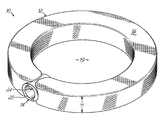
- FIG. 1 is a perspective view of one embodiment of an interbody device shown with an member in an expanded state
- FIG. 2 is a plan view of the interbody device of FIG. 1 with a partial cross section of a coupler and the member;
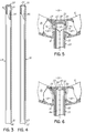
- FIGS. 3 and 4 are elevation views of embodiments of a member fill tube and a cavity fill tube, respectively, with partial cross sections of a proximal end of each;
- FIGS. 5 and 6 are enlarged partial cross sections of the member fill tube of FIG. 3 and the cavity fill tube of FIG. 4 , respectively, each individually inserted into the coupler of FIG. 2 ;
- FIG. 7 depicts a cross-sectional view taken along a transverse plane through an intervertebral disc illustrating a delivery cannula inserted therein for delivery of one embodiment of the interbody device with the member shown wrapped around a coupler;
- FIG. 8 depicts one method of placing an interbody device within the disc of FIG. 7 ;
- FIG. 9 depicts one method of providing a first filler material into the member of FIG. 8 ;
- FIG. 10 depicts one method of providing a second filler material within the member following providing the first filler material of FIG. 9 ;
- FIG. 11 depicts one embodiment of the interbody device of FIG. 10 following removal of the delivery cannula and closure of the incision in the annulus;
- FIG. 12 depicts a cross-sectional view taken along a sagittal plane through a spine illustrating one embodiment of the interbody device placed within a disc and following injection of the first filler material and the second filler material therein;
- FIG. 13 depicts an enlarged, partial cross section of an embodiment of a dual lumen fill tube inserted into the embodiment of the coupler of FIG. 2 ;
- FIG. 14 is a perspective view of another embodiment of the interbody device having a keel contiguously formed with the member;
- FIG. 15 is a plan view of the interbody device of FIG. 14 with a partial cross section of another embodiment of the coupler and the member;
- FIG. 16 depicts a cross-sectional view taken along a sagittal plane through a spine with the embodiment of the interbody device of FIG. 14 placed within a disc and following injection of the first filler material and the second filler material;
- FIG. 17 is a perspective view of another embodiment of the interbody device having a plurality of endplate anchors secured to the member thereof;
- FIG. 18 is a perspective view of one embodiment of an interbody device shown with a member in an expanded state.
- FIGS. 1 and 2 depict one embodiment of an interbody device 10 of the present invention.
- the interbody device 10 comprises a member 12 and a coupler 14 .
- the interbody device 10 is placed between adjacent vertebrae.
- tubes (embodiments of which will be described herein) configured to removably cooperate with the coupler 14 may be used to fill the member 12 with material.
- the interbody device 10 facilitates stabilization of a spine and also facilitates stabilization of adjacent vertebrae.
- the interbody device 10 with the member 12 shown in an expanded state, provides an anatomically contoured shape. While the interbody device 10 has a nearly ring-like perimeter, other shapes and configurations are possible. By way of example and not limitation, the interbody device 10 may be a customized shape designed to accommodate the patient's anatomy, particularly a shape that will treat the patient's physiological problem. Not only may the interbody device 10 have a multitude of shapes, a thickness or height H of the member 12 after it is expanded may vary around its perimeter. For instance, the interbody device 10 may form a wedge-like shape when expanded.
- the interbody device 10 may conform more readily to the patient's anatomy or may facilitate a particular treatment, e.g., the interbody device 10 may be designed to treat degenerative disc disease, stenosis, spondylolisthesis, or other disorder.
- the member 12 has a ring-like or annular shape having a flexible wall 16 .
- the flexible wall 16 surrounds an internal volume 18 , as shown in the partial cut-away view in FIG. 2 .
- the flexible wall 16 may comprise a polyester, such as DacronTM; a polymethylmethacrylate; a metallic, woven fabric made of titanium, one of its alloys, or a stainless steel; or other suitable biologically compatible material.
- the flexible wall 16 is woven, knitted, or braided. Therefore, the annular member 12 may excrete a portion of materials injected therein, as the annular member 12 is expanded to form an interior cavity 19 .
- the coupler 14 is attached to the flexible wall 16 .
- the coupler 14 may be attached to the flexible wall 16 via mechanical crimp or clamp, thermal or weld bond, adhesive, or other bonding method known in the art.
- the coupler 14 may be configured as a tube-like structure to facilitate minimally invasive insertion, as described in detail with regard to FIG. 7 .
- the coupler 14 has a first access point 20 , a second access point 22 , a first coupler side hole 24 , and a second coupler side hole 26 .
- the first access point 20 is coaxial with the second access point 22 .
- the first coupler side hole 24 opposes the second coupler side hole 26 and both the first and second coupler side holes 24 , 26 are orientated transverse to the first and second access points 20 , 22 .
- the access points 20 , 22 and side holes 24 , 26 cooperate with tubes for directing material within the interbody device 10 .
- a member fill tube 28 and a cavity fill tube 30 may be used to direct materials to the coupler 14 for distribution within the annular member 12 .
- an orthopedic system comprises the interbody device 10 of FIG. 1 , the member fill tube 28 of FIG. 3 , and the cavity fill tube 30 of FIG. 4 .
- the first access point 20 slidably receives either the member fill tube 28 of FIG. 3 or the cavity fill tube 30 of FIG. 4 , respectively.
- the coupler 14 comprises a rigid material, such as a biocompatible, thermoplastic polymer or biocompatible metal or other similar material.
- the rigid material does not sag or collapse when the member fill tube 28 is removed from the coupler 14 prior to insertion of the cavity fill tube 30 . In other words, the coupler 14 remains open sufficient to receive either tube 28 , 30 .
- the rigid material may also ease slidable engagement and removal of the cavity fill tube 30 or reengagement of the member fill tube 28 or cavity fill tube 30 should the surgeon determine that the annular member 12 requires additional material.
- the coupler 14 has an annular flange 32 .
- the annular flange 32 may project from the coupler 14 proximate the second access point 22 .
- the annular flange 32 may form the second access point 22 .
- the annular flange 32 may have other configurations, such as one or more protrusions on the coupler 14 that cooperate with one or more depressions on one or both of tubes 28 , 30 .
- the member fill tube 28 is illustrated in FIG. 3 for directing a filler material into the internal volume 18 within the interbody device 10 , as shown in FIG. 5 .
- the member fill tube 28 defines a first passage 34 that extends from a distal end 36 to a proximal end 38 .
- the distal end 36 of the member fill tube 28 has an opening 40 formed concentrically with the longitudinal axis of the tube 28 for introducing a filler material into the member fill tube 28 .
- a first tube side hole 42 and a second tube side hole 44 are formed proximate to the proximal end 38 , for example transverse to the longitudinal axis.
- the proximal end 38 is closed.
- the member fill tube 28 is removably inserted into the coupler 14 via the first access point 20 .
- the first and second tube side holes 42 , 44 at least partially align with the first coupler side hole 24 and the optional second coupler side hole 26 , respectively.
- the first and second tube side holes 42 , 44 as well as the first and second coupler side holes 24 , 26 may have different configurations and still facilitate flow of materials from the opening 40 into the internal volume 18 .
- the member fill tube 28 may also substantially block the second access point 22 e.g., with the closed proximal end 38 when the other holes 24 , 26 , and 42 , 44 , respectively, are aligned.
- the member fill tube 28 passes through the first access point 20 and docks with the second access point 22 .
- a portion of the member fill tube 28 cooperates with a portion of the coupler 14 .
- the member fill tube 28 may have the proximal end 38 configured, as shown in FIG. 5 , to cooperate with the annular flange 32 projecting from the coupler 14 .
- the cooperative engagement between the annular flange 32 and the proximal end 38 of the member fill tube 28 may provide a tactile “docking” sensation which the surgeon may identify as the proper alignment of the member fill tube 28 within the coupler 14 .
- Proper alignment may include alignment of first and second tube side holes 42 , 44 with first and second coupler side holes 24 , 26 , respectively.
- the member fill tube 28 has a length that may extend to an accessible location outside the patient to ease filling of the internal volume 18 .
- the cavity fill tube 30 is illustrated in FIG. 4 for directing a filler material into the interior cavity 19 within the interbody device 10 , as shown in FIG. 6 .
- the cavity fill tube 30 defines a second passage 46 that extends from a distal end 48 to a proximal end 50 .
- the distal end 48 of the cavity fill tube 30 has an opening 52 therein for introducing filler material into the cavity fill tube 30 , and an axial port 54 is formed in the proximal end 50 .
- the opening 52 is in fluid communication with the axial port 54 via the second passage 46 .
- the cavity fill tube 30 removably and slidably cooperates with the first and second access points 20 , 22 in the coupler 14 .
- the axial port 54 provides fluid communication between the opening 52 and the interior cavity 19 via the second passage 46 .
- the cavity fill tube 30 blocks the first and second coupler side holes 24 , 26 .
- the cavity fill tube 30 passes through the first access point 20 and docks with the second access point 22 .
- a portion of the cavity fill tube 30 cooperates with a portion of the coupler 14 to align the axial port 54 with the second access point 22 in the coupler 14 .
- the cavity fill tube 30 may have the proximal end 50 configured, as shown in FIG. 6 , similar to the proximal end 38 of the member fill tube 28 in FIG. 3 , to cooperate with the annular flange 32 projecting from the coupler 14 . Similar to the member fill tube 28 , the cooperative engagement between the annular flange 32 and the proximal end 50 of the cavity fill tube 30 may provide a tactile sensation which the surgeon may identify as the proper alignment of the cavity fill tube 30 with the coupler 14 . Furthermore, the cavity fill tube 30 has a length such that the distal end 48 may extend to an accessible location outside the patient.
- a discectomy involves resection of a portion of a nucleus 56 via an incision 58 made in an annulus 60 of a disc 62 thereby creating a disc space 64 .
- the method includes placing one embodiment of the interbody device 10 within the disc space 64 .
- a delivery cannula 66 is inserted through the incision 58 and into the disc space 64 .
- the interbody device 10 with the member fill tube 28 inserted into the coupler 14 is inserted either simultaneously with the delivery cannula 66 through the incision 58 or following initial insertion of the delivery cannula 66 through the incision 58 , i.e. as a separate insertion step.
- the coupler 14 and annular member 12 may cooperate somewhat like a trocar, known in the art, to ease passage of the coupler 14 , annular member 12 , and delivery cannula 66 through the incision 58 .
- the coupler 14 and annular member 12 may also pass through the delivery cannula 66 into the disc space 64 . It will be appreciated that the annular member 12 may be folded, wrapped, or otherwise configured for insertion through the delivery cannula 66 .
- FIG. 8 the annular member 12 in an unexpanded state is unfolded within the disc space 64 .
- a first filler material 68 is injected into the opening 40 in the distal end 36 (not shown) of the member fill tube 28 .
- the first filler material 68 passes through the first passage 34 through the coupler 14 and into the internal volume 18 of the annular member 12 (one possible flow pattern is illustrated in FIG. 9 ). While FIG. 9 clearly illustrates flow of the first filler material 68 through both sides of the coupler 14 , that is through aligned holes 24 , 42 and 26 , 44 (shown in FIG.
- annular flange 32 shown most clearly in FIG. 5 may prevent the first filler material 68 from being accidentally injected into the interior cavity 19 should the member fill tube 28 be accidentally removed following insertion of the delivery cannula 66 , annular member 12 , and member fill tube 28 through the incision 58 and thus requiring reinsertion of the member fill tube 28 .
- Expanding the annular member 12 may facilitate distraction of adjacent vertebrae and possibly decompression. The degree of distraction may depend upon the pressure used to inject the first filler material 68 and the material of the flexible wall 16 .
- the annular member 12 may excrete a portion of the first filler material 68 . Therefore, if the annular member 12 contacts the endplates 70 , 72 of the adjacent vertebrae 74 , 76 as shown in FIG. 12 , the first filler material 68 may facilitate bonding of the annular member 12 to the endplates 70 , 72 .
- the interior cavity 19 is formed.
- the member fill tube 28 may then be withdrawn.
- the coupler 14 may cooperate with the member fill tube 28 to substantially prevent the first filler material 68 from entering the coupler 14 .
- any residual first filler material 68 within the member fill tube 28 may be prevented from building up within the coupler 14 .
- the first filler material 68 may then be hardened or permitted to harden.
- the first filler material 68 is an elastomeric material that may or may not harden following placement of the fill material 68 into the internal volume 18 .
- the first filler material 68 is an in-situ curable material that hardens prior to removal of the member fill tube 28 .
- the coupler 14 may aid removal therefrom by limiting contact of the fill material 68 with the member fill tube 28 .
- slight movement, e.g., rotation, of the member fill tube 28 may break any connectivity between the in-situ curable first filler material 68 and the member fill tube 28 .
- the first filler material 68 may include bioresorbable materials; elastic materials, such as, polyurethane, silicone rubber, in-situ curable polymer (most likely an elastomer), and PVA (polyvinyl alcohol) hydrogel; or other hydrogels, or may comprise poly(lactic acid), poly(glycolic acid), p-dioxanone fibers, polyarylethyl, polymethylmethacrylate, polyurethane, amino-acid-derived polycarbonate, polycaprolactone, aliphatic polyesters, calcium phosphate, unsaturated linear polyesters, vinyl pyrrolidone, polypropylene fumarate diacrylate, polymethylmethacrylate (PMMA), bis-GMA polymer, hydrogel polyurethane, polyacrylamides, a hydrogel or combinations thereof, or other biologically compatible polymer capable of supporting axial loads transmitted through the spinal column.
- elastic materials such as, polyurethane, silicone rubber, in-situ curable polymer (most likely an
- the cavity fill tube 30 may be inserted into the coupler 14 , as shown in FIG. 10 .
- the coupler 14 may also aid in the insertion of the cavity fill tube 30 by keeping the first access point 20 free of the first filler material 68 .
- the annular flange 32 may prevent the cavity fill tube 30 from being thrust into the interior cavity 19 and potentially rupturing the flexible wall 16 .
- the second filler material 80 passes through the second passage 46 , through the coupler 14 , and into the interior cavity 19 .
- the second filler material 80 fills the interior cavity 19 formed by the interbody device 10 to contact each endplate 70 , 72 of each vertebrae 74 , 76 , as shown in FIG. 12 .
- the cavity fill tube 30 is inserted into the delivery cannula 66 to engage the coupler 14 , usually without visual assistance, though guide wires (not shown) may assist the surgeon in inserting the cavity fill tube 30 into the coupler 14 .
- guide wires (not shown) may assist the surgeon in inserting the cavity fill tube 30 into the coupler 14 .
- the annular flange 32 shown most clearly in FIG. 6 , may provide some tactile sensation that the cavity fill tube 30 has seated within the coupler 14 .
- the annular flange 32 may prevent the surgeon from inadvertently inserting the cavity fill tube 30 and damaging the annular member 12 .
- the coupler 14 may ease withdraw of the cavity fill tube 30 by substantially preventing the first filler material 68 from contaminating the cavity fill tube 30 if the first filler material 68 has not sufficiently hardened prior to its removal.
- FIG. 11 the cavity fill tube 30 is removed once the interior cavity 19 is filled with the second filler material 80 .
- the delivery cannula 66 is also removed.
- the incision 58 in the annulus 60 as well as other necessary incisions in the surrounding tissue, are closed.
- FIGS. 7-11 illustrate a posterior entry into the disc 62 ; however, as previously mentioned, other approaches are also possible.
- insertion approaches may include a posterolateral approach, transformational approach, anterior approach, anterolateral transpsoatic approach, anterior lateral retroperitoneal approach, and others.
- the second filler material 80 can be contained within the interior cavity 19 by including or weaving additional material into the interbody device 10 to create a barrier such as top and bottom walls 104 , 106 that cover the openings in the interior cavity 19 .
- These portions of the interbody device 10 may be shaped to the shape of the vertebral endplates.
- the interbody device 10 may provide support to the spine 81 by maintaining separation of the adjacent vertebrae 74 , 76 .
- the second filler material 80 is a fusion promoting material that bonds to the endplates 70 , 72 of the adjacent vertebrae 74 , 76 .
- the second filler material 80 is an elastomeric material that may be more elastic than the first filler material 68 .
- the first elastomeric material may be more than elastic than the second elastomeric material.
- filling the annular member 12 with elastomeric materials may allow it to mimic the natural kinematics associated with a healthy disc.
- Exemplary materials include, bioresorbable materials; elastic materials, such as, polyurethane, silicone rubber, in-situ curable polymer (most likely an elastomer), and PVA (polyvinyl alcohol) hydrogel; or other hydrogels, or may comprise poly(lactic acid), poly(glycolic acid), p-dioxanone fibers, polyarylethyl, polymethylmethacrylate, polyurethane, amino-acid-derived polycarbonate, polycaprolactone, aliphatic polyesters, calcium phosphate, unsaturated linear polyesters, vinyl pyrrolidone, polypropylene fumarate diacrylate, polymethylmethacrylate (PMMA), bis-GMA polymer, hydrogel polyurethane, polyacrylamides, a hydrogel or combinations thereof, or other biologically compatible polymer capable of supporting axial loads transmitted through the spinal column.
- elastic materials such as, polyurethane, silicone rubber, in-situ curable polymer (most likely an elastomer
- the system may comprise a dual lumen fill tube 82 .
- the dual lumen fill tube 82 defines a first passage 84 and a second passage 86 .
- the dual lumen fill tube 82 is inserted into the coupler 14 with the first passage 84 in fluid communication with the internal volume 18 via alignment of the first and second coupler side holes 24 , 26 with a first tube side hole 88 and a second tube side hole 90 , respectively. It will be appreciated that only one of the side holes 88 or 90 or other opening may be necessary to fill the internal volume 18 .
- the second passage 86 of the dual lumen fill tube 82 is in fluid communication with the interior cavity 19 via an axial port 92 .
- the first passage 84 may be concentric around the second passage 86 . It will be appreciated, however, that other configurations may be used, e.g. side-by-side passages.
- the arrows illustrate flow directions for both the first filler material 68 and the second filler material 80 into the internal volume 18 and the interior cavity 19 , respectively.
- providing the first filler material 68 and the second filler material 80 may proceed simultaneously, though the rate of introduction of the first filler material 68 may differ from the rate of introduction of the second filler material 80 .
- the internal volume 18 may be filled to begin formation of the interior cavity 19 .
- the second filler material 80 may then immediately follow once a sufficient portion of the interior cavity 19 has formed.
- a proximal end 94 of the dual lumen fill tube 82 cooperates with the annular flange 32 of the coupler 14 , as previously described with respect to the member fill tube 28 in FIG. 5 and the cavity fill tube 30 in FIG. 6 .
- FIGS. 14 , 15 , and 16 Another exemplary embodiment of the interbody device 10 is shown in FIGS. 14 , 15 , and 16 .
- the annular member 12 of FIG. 14 has a keel 96 projecting substantially vertically from the annular member 12 .
- the keel 96 may be formed of the flexible wall 16 and thus surround the internal volume 18 , as shown in FIG. 15 .
- the coupler 14 is elongated with a third access point 98 .
- the second and third access points 22 , 98 may be positioned on opposing sides of the coupler 14 to provide access to the interior cavity 19 adjacent the projecting keel 96 . Similar to previously described embodiments of the annular member 12 , the annular member 12 of FIG.
- first filler material 68 is filled with the first filler material 68 through the first and second coupler side holes 24 , 26 , for example, when they are aligned with the first and second tube side holes 42 , 44 of the member fill tube 28 shown in FIG. 3 , or through the first and second tube side holes 88 , 90 of the dual lumen fill tube 82 shown in FIG. 13 .
- the first filler material 68 also fills the keel 96 , for example, through its end opposite the coupler 14 , shown in FIG. 15 .
- the keel 96 may, for example, be a perpendicular extension of the annular member 12 that expands to project in a vertical direction. In one embodiment, the keel 96 may partition the interior cavity 19 into multiple components.
- the interior cavity 19 may comprise sinistral and dextral portions.
- the second filler material 80 passes out of the coupler 14 into one of the sinistral or dextral portions of the interior cavity 19 via the second or third access points 22 , 98 , respectively.
- the keel 96 may cooperate with depressions, such as channels 100 , formed in the endplates 70 , 72 of the vertebrae 74 , 76 , respectively.
- the keel 96 may expand into one or more of the channels 100 .
- the keel 96 may cooperate with the channels 100 to reduce the risk of migration of the interbody device 10 from its initial position.
- the keel 96 may have other configurations projecting toward one or both endplates 70 , 72 .
- the channels 100 may be machined into endplates 70 , 72 prior to insertion of the interbody device 10 to accept the projecting portion, such as the keel 96 .
- FIG. 17 illustrates another exemplary embodiment of the interbody device 10 .
- the annular member 12 is shown in an expanded state having a plurality of endplate anchors 102 .
- the endplate anchors 102 may be attached to the flexible wall 16 such that they may contact adjacent vertebrae.
- one or more of endplate anchors 102 may then contact one endplate 70 , 72 of the adjacent vertebra 74 , 76 .
- the endplate anchors 102 may be natural or synthetic bone, a porous metal such as TRABECULAR METALTM sold by Zimmer Spine, Inc. of Edina, Minn., or other compatible material that is osteoconductive.
- the endplate anchor 102 may also provide additional frictional engagement of the interbody device 10 with one of the endplates 70 , 72 , which may stabilize the annular member 12 for subsequent injection of the second filler material 80 .
Abstract
Description
Claims (3)
Priority Applications (2)
| Application Number | Priority Date | Filing Date | Title |
|---|---|---|---|
| US11/926,975 US8043381B2 (en) | 2007-10-29 | 2007-10-29 | Minimally invasive interbody device and method |
| PCT/US2008/080011 WO2009058566A1 (en) | 2007-10-29 | 2008-10-15 | Minimally invasive interbody device and method |
Applications Claiming Priority (1)
| Application Number | Priority Date | Filing Date | Title |
|---|---|---|---|
| US11/926,975 US8043381B2 (en) | 2007-10-29 | 2007-10-29 | Minimally invasive interbody device and method |
Publications (2)
| Publication Number | Publication Date |
|---|---|
| US20090112323A1 US20090112323A1 (en) | 2009-04-30 |
| US8043381B2 true US8043381B2 (en) | 2011-10-25 |
Family
ID=40259165
Family Applications (1)
| Application Number | Title | Priority Date | Filing Date |
|---|---|---|---|
| US11/926,975 Expired - Fee Related US8043381B2 (en) | 2007-10-29 | 2007-10-29 | Minimally invasive interbody device and method |
Country Status (2)
| Country | Link |
|---|---|
| US (1) | US8043381B2 (en) |
| WO (1) | WO2009058566A1 (en) |
Cited By (84)
| Publication number | Priority date | Publication date | Assignee | Title |
|---|---|---|---|---|
| US20090222097A1 (en) * | 2008-02-28 | 2009-09-03 | Warsaw Orthopedic, Inc. | Nucleus implant and method of installing same |
| US20100203155A1 (en) * | 2009-02-12 | 2010-08-12 | Guobao Wei | Segmented delivery system |
| US20100262240A1 (en) * | 2007-11-16 | 2010-10-14 | Kris Chavatte | Porous containment device and associated method for stabilization of vertebral compression fractures |
| US20110224790A1 (en) * | 2009-09-11 | 2011-09-15 | Articulinx, Inc. | Disc-based orthopedic devices |
| US20110319996A1 (en) * | 2008-12-22 | 2011-12-29 | Synthes Usa, Llc | Expandable vertebral body replacement device and method |
| US20140031938A1 (en) * | 2012-07-26 | 2014-01-30 | Beat Lechmann | Expandable Implant |
| US20140031939A1 (en) * | 2012-07-25 | 2014-01-30 | Steve Wolfe | Mesh spacer hybrid |
| US20140277467A1 (en) * | 2013-03-14 | 2014-09-18 | Spinal Stabilization Technologies, Llc | Prosthetic Spinal Disk Nucleus |
| US9198765B1 (en) | 2011-10-31 | 2015-12-01 | Nuvasive, Inc. | Expandable spinal fusion implants and related methods |
| US9295562B2 (en) | 2008-01-17 | 2016-03-29 | DePuy Synthes Products, Inc. | Expandable intervertebral implant and associated method of manufacturing the same |
| US9320615B2 (en) | 2010-06-29 | 2016-04-26 | DePuy Synthes Products, Inc. | Distractible intervertebral implant |
| US9402737B2 (en) | 2007-06-26 | 2016-08-02 | DePuy Synthes Products, Inc. | Highly lordosed fusion cage |
| US9414934B2 (en) | 2008-04-05 | 2016-08-16 | DePuy Synthes Products, Inc. | Expandable intervertebral implant |
| US9445918B1 (en) | 2012-10-22 | 2016-09-20 | Nuvasive, Inc. | Expandable spinal fusion implants and related instruments and methods |
| US9526620B2 (en) | 2009-03-30 | 2016-12-27 | DePuy Synthes Products, Inc. | Zero profile spinal fusion cage |
| US9539041B2 (en) | 2013-09-12 | 2017-01-10 | DePuy Synthes Products, Inc. | Minimally invasive biomaterial injection system |
| US9717601B2 (en) | 2013-02-28 | 2017-08-01 | DePuy Synthes Products, Inc. | Expandable intervertebral implant, system, kit and method |
| US9724207B2 (en) | 2003-02-14 | 2017-08-08 | DePuy Synthes Products, Inc. | In-situ formed intervertebral fusion device and method |
| US9750552B2 (en) | 2009-07-06 | 2017-09-05 | DePuy Synthes Products, Inc. | Expandable fixation assemblies |
| US20170290577A1 (en) * | 2007-10-17 | 2017-10-12 | Davol, Inc. (a C.R. Bard Company) | Fixating means between a mesh and mesh deployment means especially useful for hernia repair surgeries and methods thereof |
| US9833334B2 (en) | 2010-06-24 | 2017-12-05 | DePuy Synthes Products, Inc. | Enhanced cage insertion assembly |
| US9913727B2 (en) | 2015-07-02 | 2018-03-13 | Medos International Sarl | Expandable implant |
| US9924979B2 (en) | 2014-09-09 | 2018-03-27 | Medos International Sarl | Proximal-end securement of a minimally invasive working channel |
| US9949769B2 (en) | 2004-03-06 | 2018-04-24 | DePuy Synthes Products, Inc. | Dynamized interspinal implant |
| US9980737B2 (en) | 2014-08-04 | 2018-05-29 | Medos International Sarl | Flexible transport auger |
| US9993349B2 (en) | 2002-06-27 | 2018-06-12 | DePuy Synthes Products, Inc. | Intervertebral disc |
| US10111712B2 (en) | 2014-09-09 | 2018-10-30 | Medos International Sarl | Proximal-end securement of a minimally invasive working channel |
| US10159582B2 (en) | 2011-09-16 | 2018-12-25 | DePuy Synthes Products, Inc. | Removable, bone-securing cover plate for intervertebral fusion cage |
| US10264959B2 (en) | 2014-09-09 | 2019-04-23 | Medos International Sarl | Proximal-end securement of a minimally invasive working channel |
| US10299838B2 (en) | 2016-02-05 | 2019-05-28 | Medos International Sarl | Method and instruments for interbody fusion and posterior fixation through a single incision |
| US10314714B2 (en) | 2014-11-04 | 2019-06-11 | Spinal Stabilization Technologies Llc | Percutaneous implantable nuclear prosthesis |
| US10369015B2 (en) | 2010-09-23 | 2019-08-06 | DePuy Synthes Products, Inc. | Implant inserter having a laterally-extending dovetail engagement feature |
| US10390963B2 (en) | 2006-12-07 | 2019-08-27 | DePuy Synthes Products, Inc. | Intervertebral implant |
| US10398563B2 (en) | 2017-05-08 | 2019-09-03 | Medos International Sarl | Expandable cage |
| US10433974B2 (en) | 2003-06-30 | 2019-10-08 | DePuy Synthes Products, Inc. | Intervertebral implant with conformable endplate |
| US10500062B2 (en) | 2009-12-10 | 2019-12-10 | DePuy Synthes Products, Inc. | Bellows-like expandable interbody fusion cage |
| US10537436B2 (en) | 2016-11-01 | 2020-01-21 | DePuy Synthes Products, Inc. | Curved expandable cage |
| US10548703B2 (en) | 2008-11-21 | 2020-02-04 | C.R. Bard, Inc. | Soft tissue repair prosthesis, expandable device, and method of soft tissue repair |
| US10575967B2 (en) | 2015-09-01 | 2020-03-03 | Spinal Stabilization Technologies Llc | Implantable nuclear prosthesis |
| US10682130B2 (en) | 2015-09-04 | 2020-06-16 | Medos International Sarl | Surgical access port stabilization |
| US10786264B2 (en) | 2015-03-31 | 2020-09-29 | Medos International Sarl | Percutaneous disc clearing device |
| US10864068B2 (en) | 2008-05-07 | 2020-12-15 | Davol Inc. | Method and apparatus for repairing a hernia |
| EP3606473A4 (en) * | 2017-04-01 | 2020-12-30 | HD Lifesciences LLC | Fluid interface system for implants |
| US10888433B2 (en) | 2016-12-14 | 2021-01-12 | DePuy Synthes Products, Inc. | Intervertebral implant inserter and related methods |
| US10898309B2 (en) | 2006-11-27 | 2021-01-26 | Davol Inc. | Device especially useful for hernia repair surgeries and methods thereof |
| US10905537B2 (en) | 2010-10-05 | 2021-02-02 | C.R. Bard, Inc. | Soft tissue repair prosthesis and expandable device |
| US10940016B2 (en) | 2017-07-05 | 2021-03-09 | Medos International Sarl | Expandable intervertebral fusion cage |
| USRE48534E1 (en) | 2012-04-16 | 2021-04-27 | DePuy Synthes Products, Inc. | Detachable dilator blade |
| US11013530B2 (en) | 2019-03-08 | 2021-05-25 | Medos International Sarl | Surface features for device retention |
| US11045324B2 (en) | 2006-12-08 | 2021-06-29 | DePuy Synthes Products, Inc. | Method of implanting a curable implant material |
| US11051862B2 (en) | 2001-11-03 | 2021-07-06 | DePuy Synthes Products, Inc. | Device for straightening and stabilizing the vertebral column |
| US11116644B2 (en) | 2018-05-25 | 2021-09-14 | Mirus Llc | Multiple expansion stage interbody devices |
| US11129727B2 (en) | 2019-03-29 | 2021-09-28 | Medos International Sari | Inflatable non-distracting intervertebral implants and related methods |
| US11134987B2 (en) | 2011-10-27 | 2021-10-05 | DePuy Synthes Products, Inc. | Method and devices for a sub-splenius/supra-levator scapulae surgical access technique |
| US11219439B2 (en) | 2012-09-26 | 2022-01-11 | DePuy Synthes Products, Inc. | NIR/RED light for lateral neuroprotection |
| US11241252B2 (en) | 2019-03-22 | 2022-02-08 | Medos International Sarl | Skin foundation access portal |
| US11253368B2 (en) | 2017-02-14 | 2022-02-22 | Nanohive Medical Llc | Methods of designing high x-ray lucency lattice structures |
| US11278423B2 (en) | 2017-09-29 | 2022-03-22 | Mirus Llc | Expandable interbody devices |
| US11291558B2 (en) | 2018-07-26 | 2022-04-05 | Nanohive Medical Llc | Dynamic implant fixation plate |
| US11344424B2 (en) | 2017-06-14 | 2022-05-31 | Medos International Sarl | Expandable intervertebral implant and related methods |
| US20220233317A1 (en) * | 2021-01-28 | 2022-07-28 | The Second Affiliated Hospital And Yuying Children's Hospital Of Wenzhou Medical University | Balloon, medical device and medical procedure for discoplasty |
| US11426286B2 (en) | 2020-03-06 | 2022-08-30 | Eit Emerging Implant Technologies Gmbh | Expandable intervertebral implant |
| US11426290B2 (en) | 2015-03-06 | 2022-08-30 | DePuy Synthes Products, Inc. | Expandable intervertebral implant, system, kit and method |
| US11439380B2 (en) | 2015-09-04 | 2022-09-13 | Medos International Sarl | Surgical instrument connectors and related methods |
| US11446156B2 (en) | 2018-10-25 | 2022-09-20 | Medos International Sarl | Expandable intervertebral implant, inserter instrument, and related methods |
| US11452607B2 (en) | 2010-10-11 | 2022-09-27 | DePuy Synthes Products, Inc. | Expandable interspinous process spacer implant |
| US11497617B2 (en) | 2019-01-16 | 2022-11-15 | Nanohive Medical Llc | Variable depth implants |
| US11497619B2 (en) | 2013-03-07 | 2022-11-15 | DePuy Synthes Products, Inc. | Intervertebral implant |
| US11510788B2 (en) | 2016-06-28 | 2022-11-29 | Eit Emerging Implant Technologies Gmbh | Expandable, angularly adjustable intervertebral cages |
| US11559328B2 (en) | 2015-09-04 | 2023-01-24 | Medos International Sarl | Multi-shield spinal access system |
| US11596522B2 (en) | 2016-06-28 | 2023-03-07 | Eit Emerging Implant Technologies Gmbh | Expandable and angularly adjustable intervertebral cages with articulating joint |
| US11633287B2 (en) | 2014-11-04 | 2023-04-25 | Spinal Stabilization Technologies Llc | Percutaneous implantable nuclear prosthesis |
| US11648124B2 (en) | 2017-04-01 | 2023-05-16 | Nanohive Medical Llc | Methods of designing three-dimensional lattice structures for implants |
| US11660082B2 (en) | 2011-11-01 | 2023-05-30 | DePuy Synthes Products, Inc. | Dilation system |
| US11672562B2 (en) | 2015-09-04 | 2023-06-13 | Medos International Sarl | Multi-shield spinal access system |
| US11737743B2 (en) | 2007-10-05 | 2023-08-29 | DePuy Synthes Products, Inc. | Dilation system and method of using the same |
| US11744447B2 (en) | 2015-09-04 | 2023-09-05 | Medos International | Surgical visualization systems and related methods |
| US11744710B2 (en) | 2018-09-04 | 2023-09-05 | Spinal Stabilization Technologies Llc | Implantable nuclear prosthesis, kits, and related methods |
| US11752009B2 (en) | 2021-04-06 | 2023-09-12 | Medos International Sarl | Expandable intervertebral fusion cage |
| US11771517B2 (en) | 2021-03-12 | 2023-10-03 | Medos International Sarl | Camera position indication systems and methods |
| US11813026B2 (en) | 2019-04-05 | 2023-11-14 | Medos International Sarl | Systems, devices, and methods for providing surgical trajectory guidance |
| US11850160B2 (en) | 2021-03-26 | 2023-12-26 | Medos International Sarl | Expandable lordotic intervertebral fusion cage |
| US11911287B2 (en) | 2010-06-24 | 2024-02-27 | DePuy Synthes Products, Inc. | Lateral spondylolisthesis reduction cage |
| US11931266B2 (en) | 2016-06-07 | 2024-03-19 | Nanohive Medical Llc | Implant with independent endplates |
Families Citing this family (46)
| Publication number | Priority date | Publication date | Assignee | Title |
|---|---|---|---|---|
| EP1253854A4 (en) | 1999-03-07 | 2010-01-06 | Discure Ltd | Method and apparatus for computerized surgery |
| US20110190772A1 (en) | 2004-10-15 | 2011-08-04 | Vahid Saadat | Powered tissue modification devices and methods |
| US20100331883A1 (en) | 2004-10-15 | 2010-12-30 | Schmitz Gregory P | Access and tissue modification systems and methods |
| US8617163B2 (en) | 2004-10-15 | 2013-12-31 | Baxano Surgical, Inc. | Methods, systems and devices for carpal tunnel release |
| US8221397B2 (en) | 2004-10-15 | 2012-07-17 | Baxano, Inc. | Devices and methods for tissue modification |
| US9101386B2 (en) | 2004-10-15 | 2015-08-11 | Amendia, Inc. | Devices and methods for treating tissue |
| US9247952B2 (en) | 2004-10-15 | 2016-02-02 | Amendia, Inc. | Devices and methods for tissue access |
| US8257356B2 (en) | 2004-10-15 | 2012-09-04 | Baxano, Inc. | Guidewire exchange systems to treat spinal stenosis |
| US8048080B2 (en) | 2004-10-15 | 2011-11-01 | Baxano, Inc. | Flexible tissue rasp |
| US20070050034A1 (en) * | 2005-05-24 | 2007-03-01 | Schwardt Jeffrey D | Low-compliance expandable medical device |
| US20070042326A1 (en) * | 2005-06-01 | 2007-02-22 | Osseous Technologies Of America | Collagen antral membrane expander |
| US7988735B2 (en) * | 2005-06-15 | 2011-08-02 | Matthew Yurek | Mechanical apparatus and method for delivering materials into the inter-vertebral body space for nucleus replacement |
| US8092456B2 (en) | 2005-10-15 | 2012-01-10 | Baxano, Inc. | Multiple pathways for spinal nerve root decompression from a single access point |
| US8366712B2 (en) | 2005-10-15 | 2013-02-05 | Baxano, Inc. | Multiple pathways for spinal nerve root decompression from a single access point |
| US8062298B2 (en) | 2005-10-15 | 2011-11-22 | Baxano, Inc. | Flexible tissue removal devices and methods |
| US20080086034A1 (en) | 2006-08-29 | 2008-04-10 | Baxano, Inc. | Tissue Access Guidewire System and Method |
| AU2006318531A1 (en) * | 2005-11-22 | 2007-05-31 | Bonwrx | Method and composition for repair and reconstruction of intervertebral discs and other reconstructive surgery |
| AU2008224435B2 (en) | 2007-03-15 | 2014-01-09 | Ortho-Space Ltd. | Prosthetic devices and methods for using same |
| US7799058B2 (en) * | 2007-04-19 | 2010-09-21 | Zimmer Gmbh | Interspinous spacer |
| EP2194861A1 (en) | 2007-09-06 | 2010-06-16 | Baxano, Inc. | Method, system and apparatus for neural localization |
| US8888850B2 (en) * | 2007-11-19 | 2014-11-18 | Linares Medical Devices, Llc | Combination spacer insert and support for providing inter-cervical vertebral support |
| US8192436B2 (en) | 2007-12-07 | 2012-06-05 | Baxano, Inc. | Tissue modification devices |
| US20090240334A1 (en) * | 2008-03-19 | 2009-09-24 | Richelsoph Marc E | Vertebral device for restoration of vertebral body height |
| US7976578B2 (en) * | 2008-06-04 | 2011-07-12 | James Marvel | Buffer for a human joint and method of arthroscopically inserting |
| US8398641B2 (en) | 2008-07-01 | 2013-03-19 | Baxano, Inc. | Tissue modification devices and methods |
| US9314253B2 (en) | 2008-07-01 | 2016-04-19 | Amendia, Inc. | Tissue modification devices and methods |
| US8409206B2 (en) | 2008-07-01 | 2013-04-02 | Baxano, Inc. | Tissue modification devices and methods |
| MX348805B (en) | 2008-07-14 | 2017-06-28 | Baxano Inc | Tissue modification devices. |
| WO2010025389A2 (en) * | 2008-08-29 | 2010-03-04 | University Of Memphis Research Foundation | Nucleus containment devices, methods of fabricating the same, methods of implanting a synthetic symphysis, and methods for treating a subject having a symphysis dysfunction |
| US8906094B2 (en) * | 2008-12-31 | 2014-12-09 | Spineology, Inc. | System and method for performing percutaneous spinal interbody fusion |
| EP2405823A4 (en) | 2009-03-13 | 2012-07-04 | Baxano Inc | Flexible neural localization devices and methods |
| US8636803B2 (en) * | 2009-04-07 | 2014-01-28 | Spinal Stabilization Technologies, Llc | Percutaneous implantable nuclear prosthesis |
| US8394102B2 (en) | 2009-06-25 | 2013-03-12 | Baxano, Inc. | Surgical tools for treatment of spinal stenosis |
| KR101234733B1 (en) * | 2009-11-11 | 2013-02-19 | 윤강준 | Artificial disc apparatus |
| WO2013057566A2 (en) | 2011-10-18 | 2013-04-25 | Ortho-Space Ltd. | Prosthetic devices and methods for using same |
| CN104105459B (en) | 2011-12-07 | 2018-10-30 | 史密夫和内修有限公司 | The plastic surgery reinforcer of pit with recess |
| US9060870B2 (en) | 2012-02-05 | 2015-06-23 | Michael J. Milella, Jr. | In-situ formed spinal implant |
| US9351779B2 (en) * | 2013-01-25 | 2016-05-31 | Kyphon SÀRL | Expandable device and methods of use |
| US9295479B2 (en) | 2013-03-14 | 2016-03-29 | Spinal Stabilization Technologies, Llc | Surgical device |
| AU2016200179B2 (en) | 2015-01-14 | 2020-09-17 | Stryker European Operations Holdings Llc | Spinal implant with porous and solid surfaces |
| US10603182B2 (en) | 2015-01-14 | 2020-03-31 | Stryker European Holdings I, Llc | Spinal implant with fluid delivery capabilities |
| CA2930123A1 (en) | 2015-05-18 | 2016-11-18 | Stryker European Holdings I, Llc | Partially resorbable implants and methods |
| US10881522B2 (en) * | 2017-02-09 | 2021-01-05 | Nadi S Hibri | Radially expandable annulus reinforcement prosthesis |
| US10835388B2 (en) | 2017-09-20 | 2020-11-17 | Stryker European Operations Holdings Llc | Spinal implants |
| US11344433B2 (en) * | 2019-02-13 | 2022-05-31 | Warsaw Orthopedic, Inc. | Spinal implant system and method |
| US11376131B2 (en) * | 2020-04-07 | 2022-07-05 | Ethicon, Inc. | Cortical rim-supporting interbody device and method |
Citations (28)
| Publication number | Priority date | Publication date | Assignee | Title |
|---|---|---|---|---|
| US4433440A (en) * | 1979-02-26 | 1984-02-28 | Cohen I Kelman | Prosthesis formed by inner and outer inflatable containers |
| US4944749A (en) * | 1985-01-23 | 1990-07-31 | Hilton Becker | Implant and inflating construction |
| US5549679A (en) * | 1994-05-20 | 1996-08-27 | Kuslich; Stephen D. | Expandable fabric implant for stabilizing the spinal motion segment |
| US5630843A (en) * | 1994-06-30 | 1997-05-20 | Rosenberg; Paul H. | Double chamber tissue expander |
| US5681317A (en) * | 1996-06-12 | 1997-10-28 | Johnson & Johnson Professional, Inc. | Cement delivery system and method |
| US6017350A (en) * | 1997-10-03 | 2000-01-25 | Depuy Orthopaedics, Inc. | Pressurizer apparatus |
| US6332894B1 (en) | 2000-03-07 | 2001-12-25 | Zimmer, Inc. | Polymer filled spinal fusion cage |
| US6733533B1 (en) * | 2002-11-19 | 2004-05-11 | Zimmer Technology, Inc. | Artificial spinal disc |
| US20040127992A1 (en) * | 2002-12-31 | 2004-07-01 | Serhan Hassan A. | Annular nucleus pulposus replacement |
| US20040230309A1 (en) * | 2003-02-14 | 2004-11-18 | Depuy Spine, Inc. | In-situ formed intervertebral fusion device and method |
| US20040236425A1 (en) * | 2003-05-21 | 2004-11-25 | Shih-Shing Huang | Artificial intervertebral disc with reliable maneuverability |
| US20040249462A1 (en) * | 2003-06-06 | 2004-12-09 | Shih-Shing Huang | Artificial intervertebral disc flexibly oriented by spring-reinforced bellows |
| US20050049604A1 (en) * | 2002-05-16 | 2005-03-03 | Singer Deron J. | Device for treating intervertebral disc herniations |
| US20050090901A1 (en) * | 2001-12-05 | 2005-04-28 | Armin Studer | Intervertebral disk prosthesis or nucleus replacement prosthesis |
| US20050119752A1 (en) * | 2003-11-19 | 2005-06-02 | Synecor Llc | Artificial intervertebral disc |
| US20050278027A1 (en) * | 2004-06-11 | 2005-12-15 | Hyde Edward R Jr | Annulus fibrosus stent |
| US20060149380A1 (en) * | 2004-12-01 | 2006-07-06 | Lotz Jeffrey C | Systems, devices and methods for treatment of intervertebral disorders |
| US20060247780A1 (en) * | 2005-04-27 | 2006-11-02 | Bert Jeffrey K | Expandable artificial disc and associated methods and instrumentation |
| US20060265076A1 (en) * | 2005-05-03 | 2006-11-23 | Disc Dynamics, Inc. | Catheter holder for spinal implant |
| WO2006130796A2 (en) | 2005-06-02 | 2006-12-07 | Zimmer Spine, Inc. | Interbody fusion ring and method of using the same |
| US20060293751A1 (en) * | 2001-06-29 | 2006-12-28 | Lotz Jeffrey C | Biodegradable/bioactive nucleus pulposus implant and method for treating degenerated intervertebral discs |
| US20070038300A1 (en) * | 1994-05-06 | 2007-02-15 | Disc Dynamics, Inc. | Intervertebral disc prosthesis |
| US20070038301A1 (en) | 2005-08-10 | 2007-02-15 | Zimmer Spine, Inc. | Devices and methods for disc nucleus replacement |
| US20070078477A1 (en) * | 2005-02-04 | 2007-04-05 | Heneveld Scott H Sr | Anatomical spacer and method to deploy |
| US20070135921A1 (en) * | 2005-12-09 | 2007-06-14 | Park Kee B | Surgical implant |
| US20070173940A1 (en) * | 2006-01-18 | 2007-07-26 | Zimmer Spine, Inc. | Vertebral fusion device and method |
| US7563284B2 (en) * | 2002-08-15 | 2009-07-21 | Synthes Usa, Llc | Intervertebral disc implant |
| US7799078B2 (en) * | 2004-11-12 | 2010-09-21 | Warsaw Orthopedic, Inc. | Implantable vertebral lift |
-
2007
- 2007-10-29 US US11/926,975 patent/US8043381B2/en not_active Expired - Fee Related
-
2008
- 2008-10-15 WO PCT/US2008/080011 patent/WO2009058566A1/en active Application Filing
Patent Citations (29)
| Publication number | Priority date | Publication date | Assignee | Title |
|---|---|---|---|---|
| US4433440A (en) * | 1979-02-26 | 1984-02-28 | Cohen I Kelman | Prosthesis formed by inner and outer inflatable containers |
| US4944749A (en) * | 1985-01-23 | 1990-07-31 | Hilton Becker | Implant and inflating construction |
| US20070038300A1 (en) * | 1994-05-06 | 2007-02-15 | Disc Dynamics, Inc. | Intervertebral disc prosthesis |
| US5549679A (en) * | 1994-05-20 | 1996-08-27 | Kuslich; Stephen D. | Expandable fabric implant for stabilizing the spinal motion segment |
| US5630843A (en) * | 1994-06-30 | 1997-05-20 | Rosenberg; Paul H. | Double chamber tissue expander |
| US5681317A (en) * | 1996-06-12 | 1997-10-28 | Johnson & Johnson Professional, Inc. | Cement delivery system and method |
| US6017350A (en) * | 1997-10-03 | 2000-01-25 | Depuy Orthopaedics, Inc. | Pressurizer apparatus |
| US6332894B1 (en) | 2000-03-07 | 2001-12-25 | Zimmer, Inc. | Polymer filled spinal fusion cage |
| US20060293751A1 (en) * | 2001-06-29 | 2006-12-28 | Lotz Jeffrey C | Biodegradable/bioactive nucleus pulposus implant and method for treating degenerated intervertebral discs |
| US20050090901A1 (en) * | 2001-12-05 | 2005-04-28 | Armin Studer | Intervertebral disk prosthesis or nucleus replacement prosthesis |
| US20050049604A1 (en) * | 2002-05-16 | 2005-03-03 | Singer Deron J. | Device for treating intervertebral disc herniations |
| US7563284B2 (en) * | 2002-08-15 | 2009-07-21 | Synthes Usa, Llc | Intervertebral disc implant |
| US6733533B1 (en) * | 2002-11-19 | 2004-05-11 | Zimmer Technology, Inc. | Artificial spinal disc |
| US20040127992A1 (en) * | 2002-12-31 | 2004-07-01 | Serhan Hassan A. | Annular nucleus pulposus replacement |
| US20040230309A1 (en) * | 2003-02-14 | 2004-11-18 | Depuy Spine, Inc. | In-situ formed intervertebral fusion device and method |
| US20040236425A1 (en) * | 2003-05-21 | 2004-11-25 | Shih-Shing Huang | Artificial intervertebral disc with reliable maneuverability |
| US20040249462A1 (en) * | 2003-06-06 | 2004-12-09 | Shih-Shing Huang | Artificial intervertebral disc flexibly oriented by spring-reinforced bellows |
| US20050119752A1 (en) * | 2003-11-19 | 2005-06-02 | Synecor Llc | Artificial intervertebral disc |
| US20050278027A1 (en) * | 2004-06-11 | 2005-12-15 | Hyde Edward R Jr | Annulus fibrosus stent |
| US7799078B2 (en) * | 2004-11-12 | 2010-09-21 | Warsaw Orthopedic, Inc. | Implantable vertebral lift |
| US20060149380A1 (en) * | 2004-12-01 | 2006-07-06 | Lotz Jeffrey C | Systems, devices and methods for treatment of intervertebral disorders |
| US20070078477A1 (en) * | 2005-02-04 | 2007-04-05 | Heneveld Scott H Sr | Anatomical spacer and method to deploy |
| US20060247780A1 (en) * | 2005-04-27 | 2006-11-02 | Bert Jeffrey K | Expandable artificial disc and associated methods and instrumentation |
| US20060265076A1 (en) * | 2005-05-03 | 2006-11-23 | Disc Dynamics, Inc. | Catheter holder for spinal implant |
| WO2006130796A2 (en) | 2005-06-02 | 2006-12-07 | Zimmer Spine, Inc. | Interbody fusion ring and method of using the same |
| US20060293749A1 (en) * | 2005-06-02 | 2006-12-28 | Zimmer Spine, Inc. | Interbody fusion ring and method of using the same |
| US20070038301A1 (en) | 2005-08-10 | 2007-02-15 | Zimmer Spine, Inc. | Devices and methods for disc nucleus replacement |
| US20070135921A1 (en) * | 2005-12-09 | 2007-06-14 | Park Kee B | Surgical implant |
| US20070173940A1 (en) * | 2006-01-18 | 2007-07-26 | Zimmer Spine, Inc. | Vertebral fusion device and method |
Cited By (202)
| Publication number | Priority date | Publication date | Assignee | Title |
|---|---|---|---|---|
| US11051862B2 (en) | 2001-11-03 | 2021-07-06 | DePuy Synthes Products, Inc. | Device for straightening and stabilizing the vertebral column |
| US9993349B2 (en) | 2002-06-27 | 2018-06-12 | DePuy Synthes Products, Inc. | Intervertebral disc |
| US10238500B2 (en) | 2002-06-27 | 2019-03-26 | DePuy Synthes Products, Inc. | Intervertebral disc |
| US10575959B2 (en) | 2003-02-14 | 2020-03-03 | DePuy Synthes Products, Inc. | In-situ formed intervertebral fusion device and method |
| US9808351B2 (en) | 2003-02-14 | 2017-11-07 | DePuy Synthes Products, Inc. | In-situ formed intervertebral fusion device and method |
| US10786361B2 (en) | 2003-02-14 | 2020-09-29 | DePuy Synthes Products, Inc. | In-situ formed intervertebral fusion device and method |
| US11432938B2 (en) | 2003-02-14 | 2022-09-06 | DePuy Synthes Products, Inc. | In-situ intervertebral fusion device and method |
| US10433971B2 (en) | 2003-02-14 | 2019-10-08 | DePuy Synthes Products, Inc. | In-situ formed intervertebral fusion device and method |
| US10376372B2 (en) | 2003-02-14 | 2019-08-13 | DePuy Synthes Products, Inc. | In-situ formed intervertebral fusion device and method |
| US10085843B2 (en) | 2003-02-14 | 2018-10-02 | DePuy Synthes Products, Inc. | In-situ formed intervertebral fusion device and method |
| US10639164B2 (en) | 2003-02-14 | 2020-05-05 | DePuy Synthes Products, Inc. | In-situ formed intervertebral fusion device and method |
| US9925060B2 (en) | 2003-02-14 | 2018-03-27 | DePuy Synthes Products, Inc. | In-situ formed intervertebral fusion device and method |
| US10420651B2 (en) | 2003-02-14 | 2019-09-24 | DePuy Synthes Products, Inc. | In-situ formed intervertebral fusion device and method |
| US10583013B2 (en) | 2003-02-14 | 2020-03-10 | DePuy Synthes Products, Inc. | In-situ formed intervertebral fusion device and method |
| US9814589B2 (en) | 2003-02-14 | 2017-11-14 | DePuy Synthes Products, Inc. | In-situ formed intervertebral fusion device and method |
| US9814590B2 (en) | 2003-02-14 | 2017-11-14 | DePuy Synthes Products, Inc. | In-situ formed intervertebral fusion device and method |
| US10492918B2 (en) | 2003-02-14 | 2019-12-03 | DePuy Synthes Products, Inc. | In-situ formed intervertebral fusion device and method |
| US9801729B2 (en) | 2003-02-14 | 2017-10-31 | DePuy Synthes Products, Inc. | In-situ formed intervertebral fusion device and method |
| US9788963B2 (en) | 2003-02-14 | 2017-10-17 | DePuy Synthes Products, Inc. | In-situ formed intervertebral fusion device and method |
| US11096794B2 (en) | 2003-02-14 | 2021-08-24 | DePuy Synthes Products, Inc. | In-situ formed intervertebral fusion device and method |
| US10405986B2 (en) | 2003-02-14 | 2019-09-10 | DePuy Synthes Products, Inc. | In-situ formed intervertebral fusion device and method |
| US9724207B2 (en) | 2003-02-14 | 2017-08-08 | DePuy Synthes Products, Inc. | In-situ formed intervertebral fusion device and method |
| US10555817B2 (en) | 2003-02-14 | 2020-02-11 | DePuy Synthes Products, Inc. | In-situ formed intervertebral fusion device and method |
| US11207187B2 (en) | 2003-02-14 | 2021-12-28 | DePuy Synthes Products, Inc. | In-situ formed intervertebral fusion device and method |
| US10433974B2 (en) | 2003-06-30 | 2019-10-08 | DePuy Synthes Products, Inc. | Intervertebral implant with conformable endplate |
| US11612493B2 (en) | 2003-06-30 | 2023-03-28 | DePuy Synthes Products, Inc. | Intervertebral implant with conformable endplate |
| US10512489B2 (en) | 2004-03-06 | 2019-12-24 | DePuy Synthes Products, Inc. | Dynamized interspinal implant |
| US9949769B2 (en) | 2004-03-06 | 2018-04-24 | DePuy Synthes Products, Inc. | Dynamized interspinal implant |
| US10433881B2 (en) | 2004-03-06 | 2019-10-08 | DePuy Synthes Products, Inc. | Dynamized interspinal implant |
| US10898309B2 (en) | 2006-11-27 | 2021-01-26 | Davol Inc. | Device especially useful for hernia repair surgeries and methods thereof |
| US10398566B2 (en) | 2006-12-07 | 2019-09-03 | DePuy Synthes Products, Inc. | Intervertebral implant |
| US11273050B2 (en) | 2006-12-07 | 2022-03-15 | DePuy Synthes Products, Inc. | Intervertebral implant |
| US11497618B2 (en) | 2006-12-07 | 2022-11-15 | DePuy Synthes Products, Inc. | Intervertebral implant |
| US11660206B2 (en) | 2006-12-07 | 2023-05-30 | DePuy Synthes Products, Inc. | Intervertebral implant |
| US11712345B2 (en) | 2006-12-07 | 2023-08-01 | DePuy Synthes Products, Inc. | Intervertebral implant |
| US11432942B2 (en) | 2006-12-07 | 2022-09-06 | DePuy Synthes Products, Inc. | Intervertebral implant |
| US11642229B2 (en) | 2006-12-07 | 2023-05-09 | DePuy Synthes Products, Inc. | Intervertebral implant |
| US10583015B2 (en) | 2006-12-07 | 2020-03-10 | DePuy Synthes Products, Inc. | Intervertebral implant |
| US10390963B2 (en) | 2006-12-07 | 2019-08-27 | DePuy Synthes Products, Inc. | Intervertebral implant |
| US11045324B2 (en) | 2006-12-08 | 2021-06-29 | DePuy Synthes Products, Inc. | Method of implanting a curable implant material |
| US9402737B2 (en) | 2007-06-26 | 2016-08-02 | DePuy Synthes Products, Inc. | Highly lordosed fusion cage |
| US9839530B2 (en) | 2007-06-26 | 2017-12-12 | DePuy Synthes Products, Inc. | Highly lordosed fusion cage |
| US10973652B2 (en) | 2007-06-26 | 2021-04-13 | DePuy Synthes Products, Inc. | Highly lordosed fusion cage |
| US11622868B2 (en) | 2007-06-26 | 2023-04-11 | DePuy Synthes Products, Inc. | Highly lordosed fusion cage |
| US11737743B2 (en) | 2007-10-05 | 2023-08-29 | DePuy Synthes Products, Inc. | Dilation system and method of using the same |
| US11806223B2 (en) | 2007-10-17 | 2023-11-07 | Davol Inc. | Fixating means between a mesh and mesh deployment means especially useful for hernia repair surgeries and methods thereof |
| US20170290577A1 (en) * | 2007-10-17 | 2017-10-12 | Davol, Inc. (a C.R. Bard Company) | Fixating means between a mesh and mesh deployment means especially useful for hernia repair surgeries and methods thereof |
| US10751156B2 (en) * | 2007-10-17 | 2020-08-25 | Davol Inc. | Fixating means between a mesh and mesh deployment means especially useful for hernia repair surgeries and methods thereof |
| US8518115B2 (en) * | 2007-11-16 | 2013-08-27 | DePuy Synthes Products, LLC | Porous containment device and associated method for stabilization of vertebral compression fractures |
| US20100262240A1 (en) * | 2007-11-16 | 2010-10-14 | Kris Chavatte | Porous containment device and associated method for stabilization of vertebral compression fractures |
| US9114019B2 (en) | 2007-11-16 | 2015-08-25 | DePuy Synthes Products, Inc. | Porous containment device and associated method for stabilization of vertebral compression fractures |
| US9295562B2 (en) | 2008-01-17 | 2016-03-29 | DePuy Synthes Products, Inc. | Expandable intervertebral implant and associated method of manufacturing the same |
| US10433977B2 (en) | 2008-01-17 | 2019-10-08 | DePuy Synthes Products, Inc. | Expandable intervertebral implant and associated method of manufacturing the same |
| US9433510B2 (en) | 2008-01-17 | 2016-09-06 | DePuy Synthes Products, Inc. | Expandable intervertebral implant and associated method of manufacturing the same |
| US10449058B2 (en) | 2008-01-17 | 2019-10-22 | DePuy Synthes Products, Inc. | Expandable intervertebral implant and associated method of manufacturing the same |
| US11737881B2 (en) | 2008-01-17 | 2023-08-29 | DePuy Synthes Products, Inc. | Expandable intervertebral implant and associated method of manufacturing the same |
| US20090222097A1 (en) * | 2008-02-28 | 2009-09-03 | Warsaw Orthopedic, Inc. | Nucleus implant and method of installing same |
| US11712342B2 (en) | 2008-04-05 | 2023-08-01 | DePuy Synthes Products, Inc. | Expandable intervertebral implant |
| US9931223B2 (en) | 2008-04-05 | 2018-04-03 | DePuy Synthes Products, Inc. | Expandable intervertebral implant |
| US10449056B2 (en) | 2008-04-05 | 2019-10-22 | DePuy Synthes Products, Inc. | Expandable intervertebral implant |
| US9545314B2 (en) | 2008-04-05 | 2017-01-17 | DePuy Synthes Products, Inc. | Expandable intervertebral implant |
| US11602438B2 (en) | 2008-04-05 | 2023-03-14 | DePuy Synthes Products, Inc. | Expandable intervertebral implant |
| US9993350B2 (en) | 2008-04-05 | 2018-06-12 | DePuy Synthes Products, Inc. | Expandable intervertebral implant |
| US9414934B2 (en) | 2008-04-05 | 2016-08-16 | DePuy Synthes Products, Inc. | Expandable intervertebral implant |
| US11617655B2 (en) | 2008-04-05 | 2023-04-04 | DePuy Synthes Products, Inc. | Expandable intervertebral implant |
| US11712341B2 (en) | 2008-04-05 | 2023-08-01 | DePuy Synthes Products, Inc. | Expandable intervertebral implant |
| US11707359B2 (en) | 2008-04-05 | 2023-07-25 | DePuy Synthes Products, Inc. | Expandable intervertebral implant |
| US9474623B2 (en) | 2008-04-05 | 2016-10-25 | DePuy Synthes Products, Inc. | Expandable intervertebral implant |
| US9597195B2 (en) | 2008-04-05 | 2017-03-21 | DePuy Synthes Products, Inc. | Expandable intervertebral implant |
| US9526625B2 (en) | 2008-04-05 | 2016-12-27 | DePuy Synthes Products, Inc. | Expandable intervertebral implant |
| US11701234B2 (en) | 2008-04-05 | 2023-07-18 | DePuy Synthes Products, Inc. | Expandable intervertebral implant |
| US10864068B2 (en) | 2008-05-07 | 2020-12-15 | Davol Inc. | Method and apparatus for repairing a hernia |
| US10548703B2 (en) | 2008-11-21 | 2020-02-04 | C.R. Bard, Inc. | Soft tissue repair prosthesis, expandable device, and method of soft tissue repair |
| US8632592B2 (en) * | 2008-12-22 | 2014-01-21 | DePuy Synthes Products, LLC | Expandable vertebral body replacement device and method |
| US20110319996A1 (en) * | 2008-12-22 | 2011-12-29 | Synthes Usa, Llc | Expandable vertebral body replacement device and method |
| US9101475B2 (en) * | 2009-02-12 | 2015-08-11 | Warsaw Orthopedic, Inc. | Segmented delivery system |
| US20100203155A1 (en) * | 2009-02-12 | 2010-08-12 | Guobao Wei | Segmented delivery system |
| US9592129B2 (en) | 2009-03-30 | 2017-03-14 | DePuy Synthes Products, Inc. | Zero profile spinal fusion cage |
| US10624758B2 (en) | 2009-03-30 | 2020-04-21 | DePuy Synthes Products, Inc. | Zero profile spinal fusion cage |
| US9526620B2 (en) | 2009-03-30 | 2016-12-27 | DePuy Synthes Products, Inc. | Zero profile spinal fusion cage |
| US11612491B2 (en) | 2009-03-30 | 2023-03-28 | DePuy Synthes Products, Inc. | Zero profile spinal fusion cage |
| US9750552B2 (en) | 2009-07-06 | 2017-09-05 | DePuy Synthes Products, Inc. | Expandable fixation assemblies |
| US20110224790A1 (en) * | 2009-09-11 | 2011-09-15 | Articulinx, Inc. | Disc-based orthopedic devices |
| US8292954B2 (en) * | 2009-09-11 | 2012-10-23 | Articulinx, Inc. | Disc-based orthopedic devices |
| US8764830B2 (en) | 2009-09-11 | 2014-07-01 | Articulinx, Inc. | Disc-shaped orthopedic devices |
| US11607321B2 (en) | 2009-12-10 | 2023-03-21 | DePuy Synthes Products, Inc. | Bellows-like expandable interbody fusion cage |
| US10500062B2 (en) | 2009-12-10 | 2019-12-10 | DePuy Synthes Products, Inc. | Bellows-like expandable interbody fusion cage |
| US9895236B2 (en) | 2010-06-24 | 2018-02-20 | DePuy Synthes Products, Inc. | Enhanced cage insertion assembly |
| US9833334B2 (en) | 2010-06-24 | 2017-12-05 | DePuy Synthes Products, Inc. | Enhanced cage insertion assembly |
| US10327911B2 (en) | 2010-06-24 | 2019-06-25 | DePuy Synthes Products, Inc. | Enhanced cage insertion assembly |
| US10966840B2 (en) | 2010-06-24 | 2021-04-06 | DePuy Synthes Products, Inc. | Enhanced cage insertion assembly |
| US11872139B2 (en) | 2010-06-24 | 2024-01-16 | DePuy Synthes Products, Inc. | Enhanced cage insertion assembly |
| US11911287B2 (en) | 2010-06-24 | 2024-02-27 | DePuy Synthes Products, Inc. | Lateral spondylolisthesis reduction cage |
| US10548741B2 (en) | 2010-06-29 | 2020-02-04 | DePuy Synthes Products, Inc. | Distractible intervertebral implant |
| US9320615B2 (en) | 2010-06-29 | 2016-04-26 | DePuy Synthes Products, Inc. | Distractible intervertebral implant |
| US11654033B2 (en) | 2010-06-29 | 2023-05-23 | DePuy Synthes Products, Inc. | Distractible intervertebral implant |
| US9579215B2 (en) | 2010-06-29 | 2017-02-28 | DePuy Synthes Products, Inc. | Distractible intervertebral implant |
| US10369015B2 (en) | 2010-09-23 | 2019-08-06 | DePuy Synthes Products, Inc. | Implant inserter having a laterally-extending dovetail engagement feature |
| US10905537B2 (en) | 2010-10-05 | 2021-02-02 | C.R. Bard, Inc. | Soft tissue repair prosthesis and expandable device |
| US11452607B2 (en) | 2010-10-11 | 2022-09-27 | DePuy Synthes Products, Inc. | Expandable interspinous process spacer implant |
| US10813773B2 (en) | 2011-09-16 | 2020-10-27 | DePuy Synthes Products, Inc. | Removable, bone-securing cover plate for intervertebral fusion cage |
| US10159582B2 (en) | 2011-09-16 | 2018-12-25 | DePuy Synthes Products, Inc. | Removable, bone-securing cover plate for intervertebral fusion cage |
| US11134987B2 (en) | 2011-10-27 | 2021-10-05 | DePuy Synthes Products, Inc. | Method and devices for a sub-splenius/supra-levator scapulae surgical access technique |
| US11234736B2 (en) | 2011-10-27 | 2022-02-01 | DePuy Synthes Products, Inc. | Method and devices for a sub-splenius/supra-levator scapulae surgical access technique |
| US11937797B2 (en) | 2011-10-27 | 2024-03-26 | DePuy Synthes Products, Inc. | Method and devices for a sub-splenius/supra-levator scapulae surgical access technique |
| US11911017B2 (en) | 2011-10-27 | 2024-02-27 | DePuy Synthes Products, Inc. | Method and devices for a sub-splenius/supra-levator scapulae surgical access technique |
| US11278323B2 (en) | 2011-10-27 | 2022-03-22 | DePuy Synthes Products, Inc. | Method and devices for a sub-splenius/supra-levator scapulae surgical access technique |
| US11241255B2 (en) | 2011-10-27 | 2022-02-08 | DePuy Synthes Products, Inc. | Method and devices for a sub-splenius/supra-levator scapulae surgical access technique |
| US9655744B1 (en) | 2011-10-31 | 2017-05-23 | Nuvasive, Inc. | Expandable spinal fusion implants and related methods |
| US9198765B1 (en) | 2011-10-31 | 2015-12-01 | Nuvasive, Inc. | Expandable spinal fusion implants and related methods |
| US11660082B2 (en) | 2011-11-01 | 2023-05-30 | DePuy Synthes Products, Inc. | Dilation system |
| USRE48534E1 (en) | 2012-04-16 | 2021-04-27 | DePuy Synthes Products, Inc. | Detachable dilator blade |
| US9925058B2 (en) | 2012-07-25 | 2018-03-27 | Spineology Inc. | Mesh spacer hybrid |
| US20140031939A1 (en) * | 2012-07-25 | 2014-01-30 | Steve Wolfe | Mesh spacer hybrid |
| US10111756B2 (en) | 2012-07-25 | 2018-10-30 | Spineology Inc. | Mesh spacer hybrid |
| US20140031938A1 (en) * | 2012-07-26 | 2014-01-30 | Beat Lechmann | Expandable Implant |
| US8940052B2 (en) * | 2012-07-26 | 2015-01-27 | DePuy Synthes Products, LLC | Expandable implant |
| US10058433B2 (en) | 2012-07-26 | 2018-08-28 | DePuy Synthes Products, Inc. | Expandable implant |
| US9561117B2 (en) | 2012-07-26 | 2017-02-07 | DePuy Synthes Products, Inc. | Expandable implant |
| US11559295B2 (en) | 2012-09-26 | 2023-01-24 | DePuy Synthes Products, Inc. | NIR/red light for lateral neuroprotection |
| US11219439B2 (en) | 2012-09-26 | 2022-01-11 | DePuy Synthes Products, Inc. | NIR/RED light for lateral neuroprotection |
| US10350084B1 (en) | 2012-10-22 | 2019-07-16 | Nuvasive, Inc. | Expandable spinal fusion implant, related instruments and methods |
| US11399954B2 (en) | 2012-10-22 | 2022-08-02 | Nuvasive, Inc. | Expandable spinal fusion implant, related instruments and methods |
| US9445918B1 (en) | 2012-10-22 | 2016-09-20 | Nuvasive, Inc. | Expandable spinal fusion implants and related instruments and methods |
| US9717601B2 (en) | 2013-02-28 | 2017-08-01 | DePuy Synthes Products, Inc. | Expandable intervertebral implant, system, kit and method |
| US11497619B2 (en) | 2013-03-07 | 2022-11-15 | DePuy Synthes Products, Inc. | Intervertebral implant |
| US11850164B2 (en) | 2013-03-07 | 2023-12-26 | DePuy Synthes Products, Inc. | Intervertebral implant |
| US9545321B2 (en) | 2013-03-14 | 2017-01-17 | Spinal Stabilization Technologies Llc | Prosthetic spinal disk nucleus |
| US20140277467A1 (en) * | 2013-03-14 | 2014-09-18 | Spinal Stabilization Technologies, Llc | Prosthetic Spinal Disk Nucleus |
| US11406513B2 (en) | 2013-03-14 | 2022-08-09 | Spinal Stabilization Technologies, Llc | Prosthetic spinal disk nucleus |
| US10660762B2 (en) | 2013-09-12 | 2020-05-26 | DePuy Synthes Product, Inc. | Minimally invasive biomaterial injection system |
| US9539041B2 (en) | 2013-09-12 | 2017-01-10 | DePuy Synthes Products, Inc. | Minimally invasive biomaterial injection system |
| US9980737B2 (en) | 2014-08-04 | 2018-05-29 | Medos International Sarl | Flexible transport auger |
| US11712252B2 (en) | 2014-08-04 | 2023-08-01 | Medos International Sarl | Flexible transport auger |
| US10863994B2 (en) | 2014-08-04 | 2020-12-15 | Medos International Sàrl | Flexible transport auger |
| US10111712B2 (en) | 2014-09-09 | 2018-10-30 | Medos International Sarl | Proximal-end securement of a minimally invasive working channel |
| US10264959B2 (en) | 2014-09-09 | 2019-04-23 | Medos International Sarl | Proximal-end securement of a minimally invasive working channel |
| US11213196B2 (en) | 2014-09-09 | 2022-01-04 | Medos International Sarl | Proximal-end securement of a minimally invasive working channel |
| US10786330B2 (en) | 2014-09-09 | 2020-09-29 | Medos International Sarl | Proximal-end securement of a minimally invasive working channel |
| US9924979B2 (en) | 2014-09-09 | 2018-03-27 | Medos International Sarl | Proximal-end securement of a minimally invasive working channel |
| US10314714B2 (en) | 2014-11-04 | 2019-06-11 | Spinal Stabilization Technologies Llc | Percutaneous implantable nuclear prosthesis |
| US11633287B2 (en) | 2014-11-04 | 2023-04-25 | Spinal Stabilization Technologies Llc | Percutaneous implantable nuclear prosthesis |
| US11638649B2 (en) | 2014-11-04 | 2023-05-02 | Spinal Stabilization Technologies Llc | Percutaneous implantable nuclear prosthesis |
| US11426290B2 (en) | 2015-03-06 | 2022-08-30 | DePuy Synthes Products, Inc. | Expandable intervertebral implant, system, kit and method |
| US11464523B2 (en) | 2015-03-31 | 2022-10-11 | Medos International Sarl | Percutaneous disc clearing device |
| US10786264B2 (en) | 2015-03-31 | 2020-09-29 | Medos International Sarl | Percutaneous disc clearing device |
| US9913727B2 (en) | 2015-07-02 | 2018-03-13 | Medos International Sarl | Expandable implant |
| US10575967B2 (en) | 2015-09-01 | 2020-03-03 | Spinal Stabilization Technologies Llc | Implantable nuclear prosthesis |
| US11576793B2 (en) | 2015-09-01 | 2023-02-14 | Spinal Stabilization Technologies Llc | Implantable nuclear prosthesis |
| US10874425B2 (en) | 2015-09-04 | 2020-12-29 | Medos International Sarl | Multi-shield spinal access system |
| US11000312B2 (en) | 2015-09-04 | 2021-05-11 | Medos International Sarl | Multi-shield spinal access system |
| US11883064B2 (en) | 2015-09-04 | 2024-01-30 | Medos International Sarl | Multi-shield spinal access system |
| US10779810B2 (en) | 2015-09-04 | 2020-09-22 | Medos International Sarl | Devices and methods for surgical retraction |
| US11559328B2 (en) | 2015-09-04 | 2023-01-24 | Medos International Sarl | Multi-shield spinal access system |
| US11744447B2 (en) | 2015-09-04 | 2023-09-05 | Medos International | Surgical visualization systems and related methods |
| US11712264B2 (en) | 2015-09-04 | 2023-08-01 | Medos International Sarl | Multi-shield spinal access system |
| US10758220B2 (en) | 2015-09-04 | 2020-09-01 | Medos International Sarl | Devices and methods for providing surgical access |
| US11793546B2 (en) | 2015-09-04 | 2023-10-24 | Medos International Sarl | Surgical visualization systems and related methods |
| US11331090B2 (en) | 2015-09-04 | 2022-05-17 | Medos International Sarl | Surgical visualization systems and related methods |
| US10869659B2 (en) | 2015-09-04 | 2020-12-22 | Medos International Sarl | Surgical instrument connectors and related methods |
| US10682130B2 (en) | 2015-09-04 | 2020-06-16 | Medos International Sarl | Surgical access port stabilization |
| US11950766B2 (en) | 2015-09-04 | 2024-04-09 | Medos International Sàrl | Surgical visualization systems and related methods |
| US11439380B2 (en) | 2015-09-04 | 2022-09-13 | Medos International Sarl | Surgical instrument connectors and related methods |
| US11801070B2 (en) | 2015-09-04 | 2023-10-31 | Medos International Sarl | Surgical access port stabilization |
| US11806043B2 (en) | 2015-09-04 | 2023-11-07 | Medos International Sarl | Devices and methods for providing surgical access |
| US10987129B2 (en) | 2015-09-04 | 2021-04-27 | Medos International Sarl | Multi-shield spinal access system |
| US11672562B2 (en) | 2015-09-04 | 2023-06-13 | Medos International Sarl | Multi-shield spinal access system |
| US11344190B2 (en) | 2015-09-04 | 2022-05-31 | Medos International Sarl | Surgical visualization systems and related methods |
| US10299838B2 (en) | 2016-02-05 | 2019-05-28 | Medos International Sarl | Method and instruments for interbody fusion and posterior fixation through a single incision |
| US11020153B2 (en) | 2016-02-05 | 2021-06-01 | Medos International Sarl | Method and instruments for interbody fusion and posterior fixation through a single incision |
| US11931266B2 (en) | 2016-06-07 | 2024-03-19 | Nanohive Medical Llc | Implant with independent endplates |
| US11510788B2 (en) | 2016-06-28 | 2022-11-29 | Eit Emerging Implant Technologies Gmbh | Expandable, angularly adjustable intervertebral cages |
| US11596523B2 (en) | 2016-06-28 | 2023-03-07 | Eit Emerging Implant Technologies Gmbh | Expandable and angularly adjustable articulating intervertebral cages |
| US11596522B2 (en) | 2016-06-28 | 2023-03-07 | Eit Emerging Implant Technologies Gmbh | Expandable and angularly adjustable intervertebral cages with articulating joint |
| US10537436B2 (en) | 2016-11-01 | 2020-01-21 | DePuy Synthes Products, Inc. | Curved expandable cage |
| US10888433B2 (en) | 2016-12-14 | 2021-01-12 | DePuy Synthes Products, Inc. | Intervertebral implant inserter and related methods |
| US11253368B2 (en) | 2017-02-14 | 2022-02-22 | Nanohive Medical Llc | Methods of designing high x-ray lucency lattice structures |
| US11648124B2 (en) | 2017-04-01 | 2023-05-16 | Nanohive Medical Llc | Methods of designing three-dimensional lattice structures for implants |
| EP3606473A4 (en) * | 2017-04-01 | 2020-12-30 | HD Lifesciences LLC | Fluid interface system for implants |
| US11806240B2 (en) | 2017-04-01 | 2023-11-07 | Nanohive Medical Llc | Three-dimensional lattice structures for implants |
| US10398563B2 (en) | 2017-05-08 | 2019-09-03 | Medos International Sarl | Expandable cage |
| US11446155B2 (en) | 2017-05-08 | 2022-09-20 | Medos International Sarl | Expandable cage |
| US11344424B2 (en) | 2017-06-14 | 2022-05-31 | Medos International Sarl | Expandable intervertebral implant and related methods |
| US10940016B2 (en) | 2017-07-05 | 2021-03-09 | Medos International Sarl | Expandable intervertebral fusion cage |
| US11278423B2 (en) | 2017-09-29 | 2022-03-22 | Mirus Llc | Expandable interbody devices |
| US11883301B2 (en) | 2017-09-29 | 2024-01-30 | Mirus Llc | Expandable interbody devices |
| US11116644B2 (en) | 2018-05-25 | 2021-09-14 | Mirus Llc | Multiple expansion stage interbody devices |
| US11291558B2 (en) | 2018-07-26 | 2022-04-05 | Nanohive Medical Llc | Dynamic implant fixation plate |
| US11744710B2 (en) | 2018-09-04 | 2023-09-05 | Spinal Stabilization Technologies Llc | Implantable nuclear prosthesis, kits, and related methods |
| US11446156B2 (en) | 2018-10-25 | 2022-09-20 | Medos International Sarl | Expandable intervertebral implant, inserter instrument, and related methods |
| US11497617B2 (en) | 2019-01-16 | 2022-11-15 | Nanohive Medical Llc | Variable depth implants |
| US11013530B2 (en) | 2019-03-08 | 2021-05-25 | Medos International Sarl | Surface features for device retention |
| US11241252B2 (en) | 2019-03-22 | 2022-02-08 | Medos International Sarl | Skin foundation access portal |
| US11129727B2 (en) | 2019-03-29 | 2021-09-28 | Medos International Sari | Inflatable non-distracting intervertebral implants and related methods |
| US11813026B2 (en) | 2019-04-05 | 2023-11-14 | Medos International Sarl | Systems, devices, and methods for providing surgical trajectory guidance |
| US11426286B2 (en) | 2020-03-06 | 2022-08-30 | Eit Emerging Implant Technologies Gmbh | Expandable intervertebral implant |
| US11806245B2 (en) | 2020-03-06 | 2023-11-07 | Eit Emerging Implant Technologies Gmbh | Expandable intervertebral implant |
| US20220233317A1 (en) * | 2021-01-28 | 2022-07-28 | The Second Affiliated Hospital And Yuying Children's Hospital Of Wenzhou Medical University | Balloon, medical device and medical procedure for discoplasty |
| US11771562B2 (en) * | 2021-01-28 | 2023-10-03 | The Second Affiliated Hospital And Yuying Children's Hospital Of Wenzhou Medical University | Balloon, medical device and medical procedure for discoplasty |
| US11771517B2 (en) | 2021-03-12 | 2023-10-03 | Medos International Sarl | Camera position indication systems and methods |
| US11850160B2 (en) | 2021-03-26 | 2023-12-26 | Medos International Sarl | Expandable lordotic intervertebral fusion cage |
| US11752009B2 (en) | 2021-04-06 | 2023-09-12 | Medos International Sarl | Expandable intervertebral fusion cage |
Also Published As
| Publication number | Publication date |
|---|---|
| WO2009058566A1 (en) | 2009-05-07 |
| US20090112323A1 (en) | 2009-04-30 |
Similar Documents
| Publication | Publication Date | Title |
|---|---|---|
| US8043381B2 (en) | Minimally invasive interbody device and method | |
| CA2552806C (en) | Method, system and apparatus for interbody fusion | |
| US20180303620A1 (en) | Spinal tissue distraction devices | |
| US7799079B2 (en) | Vertebral fusion device and method | |
| US10314718B2 (en) | Expandable intervertebral fusion implant | |
| US8747473B2 (en) | Modular lateral expansion device | |
| US11213402B2 (en) | Endoscopically implantable inflatable interbody fusion device | |
| CN114845669A (en) | Spinal implant with surface protrusions |
Legal Events
| Date | Code | Title | Description |
|---|---|---|---|
| AS | Assignment |
Owner name: ZIMMER SPINE, INC., MINNESOTA Free format text: ASSIGNMENT OF ASSIGNORS INTEREST;ASSIGNORS:HESTAD, HUGH D.;HUDGINS, ROBERT G.;MAERTENS, JOHN;REEL/FRAME:020409/0001;SIGNING DATES FROM 20071026 TO 20080123 Owner name: ZIMMER SPINE, INC., MINNESOTA Free format text: ASSIGNMENT OF ASSIGNORS INTEREST;ASSIGNORS:HESTAD, HUGH D.;HUDGINS, ROBERT G.;MAERTENS, JOHN;SIGNING DATES FROM 20071026 TO 20080123;REEL/FRAME:020409/0001 |
|
| STCF | Information on status: patent grant |
Free format text: PATENTED CASE |
|
| CC | Certificate of correction | ||
| FPAY | Fee payment |
Year of fee payment: 4 |
|
| FEPP | Fee payment procedure |
Free format text: MAINTENANCE FEE REMINDER MAILED (ORIGINAL EVENT CODE: REM.); ENTITY STATUS OF PATENT OWNER: LARGE ENTITY |
|
| LAPS | Lapse for failure to pay maintenance fees |
Free format text: PATENT EXPIRED FOR FAILURE TO PAY MAINTENANCE FEES (ORIGINAL EVENT CODE: EXP.); ENTITY STATUS OF PATENT OWNER: LARGE ENTITY |
|
| STCH | Information on status: patent discontinuation |
Free format text: PATENT EXPIRED DUE TO NONPAYMENT OF MAINTENANCE FEES UNDER 37 CFR 1.362 |
|
| FP | Expired due to failure to pay maintenance fee |
Effective date: 20191025 |