US8043394B2 - Particulate matter filter assembly with a flow device - Google Patents
Particulate matter filter assembly with a flow device Download PDFInfo
- Publication number
- US8043394B2 US8043394B2 US12/251,734 US25173408A US8043394B2 US 8043394 B2 US8043394 B2 US 8043394B2 US 25173408 A US25173408 A US 25173408A US 8043394 B2 US8043394 B2 US 8043394B2
- Authority
- US
- United States
- Prior art keywords
- exhaust stream
- flow
- filter assembly
- blades
- axis
- Prior art date
- Legal status (The legal status is an assumption and is not a legal conclusion. Google has not performed a legal analysis and makes no representation as to the accuracy of the status listed.)
- Expired - Fee Related, expires
Links
- 239000013618 particulate matter Substances 0.000 title claims abstract description 85
- 238000000034 method Methods 0.000 claims abstract description 11
- 238000001914 filtration Methods 0.000 claims abstract description 4
- 239000007789 gas Substances 0.000 description 38
- MWUXSHHQAYIFBG-UHFFFAOYSA-N Nitric oxide Chemical compound O=[N] MWUXSHHQAYIFBG-UHFFFAOYSA-N 0.000 description 10
- 230000008929 regeneration Effects 0.000 description 7
- 238000011069 regeneration method Methods 0.000 description 7
- 239000003638 chemical reducing agent Substances 0.000 description 4
- 238000009826 distribution Methods 0.000 description 4
- 239000000446 fuel Substances 0.000 description 4
- 239000000758 substrate Substances 0.000 description 4
- 238000011144 upstream manufacturing Methods 0.000 description 4
- XSQUKJJJFZCRTK-UHFFFAOYSA-N Urea Chemical compound NC(N)=O XSQUKJJJFZCRTK-UHFFFAOYSA-N 0.000 description 3
- QGZKDVFQNNGYKY-UHFFFAOYSA-N ammonia Natural products N QGZKDVFQNNGYKY-UHFFFAOYSA-N 0.000 description 3
- 239000004202 carbamide Substances 0.000 description 3
- 239000003054 catalyst Substances 0.000 description 3
- 238000002485 combustion reaction Methods 0.000 description 3
- 150000001875 compounds Chemical class 0.000 description 3
- 239000002283 diesel fuel Substances 0.000 description 3
- 229930195733 hydrocarbon Natural products 0.000 description 3
- 150000002430 hydrocarbons Chemical class 0.000 description 3
- 238000005304 joining Methods 0.000 description 3
- 239000002184 metal Substances 0.000 description 3
- 239000000203 mixture Substances 0.000 description 3
- 229910021529 ammonia Inorganic materials 0.000 description 2
- 238000010531 catalytic reduction reaction Methods 0.000 description 2
- 230000000295 complement effect Effects 0.000 description 2
- 238000010586 diagram Methods 0.000 description 2
- 238000011068 loading method Methods 0.000 description 2
- 239000000463 material Substances 0.000 description 2
- KJLLKLRVCJAFRY-UHFFFAOYSA-N mebutizide Chemical compound ClC1=C(S(N)(=O)=O)C=C2S(=O)(=O)NC(C(C)C(C)CC)NC2=C1 KJLLKLRVCJAFRY-UHFFFAOYSA-N 0.000 description 2
- -1 nitrogen oxide (NOx) Chemical class 0.000 description 2
- 229910000619 316 stainless steel Inorganic materials 0.000 description 1
- UGFAIRIUMAVXCW-UHFFFAOYSA-N Carbon monoxide Chemical class [O+]#[C-] UGFAIRIUMAVXCW-UHFFFAOYSA-N 0.000 description 1
- 230000000712 assembly Effects 0.000 description 1
- 238000000429 assembly Methods 0.000 description 1
- 229910002090 carbon oxide Inorganic materials 0.000 description 1
- 230000006835 compression Effects 0.000 description 1
- 238000007906 compression Methods 0.000 description 1
- 239000000470 constituent Substances 0.000 description 1
- 238000010276 construction Methods 0.000 description 1
- 229910052878 cordierite Inorganic materials 0.000 description 1
- JSKIRARMQDRGJZ-UHFFFAOYSA-N dimagnesium dioxido-bis[(1-oxido-3-oxo-2,4,6,8,9-pentaoxa-1,3-disila-5,7-dialuminabicyclo[3.3.1]nonan-7-yl)oxy]silane Chemical compound [Mg++].[Mg++].[O-][Si]([O-])(O[Al]1O[Al]2O[Si](=O)O[Si]([O-])(O1)O2)O[Al]1O[Al]2O[Si](=O)O[Si]([O-])(O1)O2 JSKIRARMQDRGJZ-UHFFFAOYSA-N 0.000 description 1
- 239000012530 fluid Substances 0.000 description 1
- 238000004519 manufacturing process Methods 0.000 description 1
- 238000002156 mixing Methods 0.000 description 1
- 238000012986 modification Methods 0.000 description 1
- 230000004048 modification Effects 0.000 description 1
- 230000003647 oxidation Effects 0.000 description 1
- 238000007254 oxidation reaction Methods 0.000 description 1
- 238000013031 physical testing Methods 0.000 description 1
- HBMJWWWQQXIZIP-UHFFFAOYSA-N silicon carbide Chemical compound [Si+]#[C-] HBMJWWWQQXIZIP-UHFFFAOYSA-N 0.000 description 1
- 229910010271 silicon carbide Inorganic materials 0.000 description 1
- 239000004071 soot Substances 0.000 description 1
- 229910001220 stainless steel Inorganic materials 0.000 description 1
- 239000010935 stainless steel Substances 0.000 description 1
- 238000003466 welding Methods 0.000 description 1
Images


Classifications
-
- F—MECHANICAL ENGINEERING; LIGHTING; HEATING; WEAPONS; BLASTING
- F01—MACHINES OR ENGINES IN GENERAL; ENGINE PLANTS IN GENERAL; STEAM ENGINES
- F01N—GAS-FLOW SILENCERS OR EXHAUST APPARATUS FOR MACHINES OR ENGINES IN GENERAL; GAS-FLOW SILENCERS OR EXHAUST APPARATUS FOR INTERNAL COMBUSTION ENGINES
- F01N3/00—Exhaust or silencing apparatus having means for purifying, rendering innocuous, or otherwise treating exhaust
- F01N3/02—Exhaust or silencing apparatus having means for purifying, rendering innocuous, or otherwise treating exhaust for cooling, or for removing solid constituents of, exhaust
- F01N3/021—Exhaust or silencing apparatus having means for purifying, rendering innocuous, or otherwise treating exhaust for cooling, or for removing solid constituents of, exhaust by means of filters
- F01N3/022—Exhaust or silencing apparatus having means for purifying, rendering innocuous, or otherwise treating exhaust for cooling, or for removing solid constituents of, exhaust by means of filters characterised by specially adapted filtering structure, e.g. honeycomb, mesh or fibrous
- F01N3/0222—Exhaust or silencing apparatus having means for purifying, rendering innocuous, or otherwise treating exhaust for cooling, or for removing solid constituents of, exhaust by means of filters characterised by specially adapted filtering structure, e.g. honeycomb, mesh or fibrous the structure being monolithic, e.g. honeycombs
-
- B—PERFORMING OPERATIONS; TRANSPORTING
- B01—PHYSICAL OR CHEMICAL PROCESSES OR APPARATUS IN GENERAL
- B01F—MIXING, e.g. DISSOLVING, EMULSIFYING OR DISPERSING
- B01F23/00—Mixing according to the phases to be mixed, e.g. dispersing or emulsifying
- B01F23/20—Mixing gases with liquids
- B01F23/21—Mixing gases with liquids by introducing liquids into gaseous media
- B01F23/213—Mixing gases with liquids by introducing liquids into gaseous media by spraying or atomising of the liquids
- B01F23/2132—Mixing gases with liquids by introducing liquids into gaseous media by spraying or atomising of the liquids using nozzles
-
- B—PERFORMING OPERATIONS; TRANSPORTING
- B01—PHYSICAL OR CHEMICAL PROCESSES OR APPARATUS IN GENERAL
- B01F—MIXING, e.g. DISSOLVING, EMULSIFYING OR DISPERSING
- B01F25/00—Flow mixers; Mixers for falling materials, e.g. solid particles
- B01F25/40—Static mixers
- B01F25/42—Static mixers in which the mixing is affected by moving the components jointly in changing directions, e.g. in tubes provided with baffles or obstructions
- B01F25/43—Mixing tubes, e.g. wherein the material is moved in a radial or partly reversed direction
- B01F25/431—Straight mixing tubes with baffles or obstructions that do not cause substantial pressure drop; Baffles therefor
- B01F25/4315—Straight mixing tubes with baffles or obstructions that do not cause substantial pressure drop; Baffles therefor the baffles being deformed flat pieces of material
-
- B—PERFORMING OPERATIONS; TRANSPORTING
- B01—PHYSICAL OR CHEMICAL PROCESSES OR APPARATUS IN GENERAL
- B01F—MIXING, e.g. DISSOLVING, EMULSIFYING OR DISPERSING
- B01F25/00—Flow mixers; Mixers for falling materials, e.g. solid particles
- B01F25/40—Static mixers
- B01F25/42—Static mixers in which the mixing is affected by moving the components jointly in changing directions, e.g. in tubes provided with baffles or obstructions
- B01F25/43—Mixing tubes, e.g. wherein the material is moved in a radial or partly reversed direction
- B01F25/431—Straight mixing tubes with baffles or obstructions that do not cause substantial pressure drop; Baffles therefor
- B01F25/43197—Straight mixing tubes with baffles or obstructions that do not cause substantial pressure drop; Baffles therefor characterised by the mounting of the baffles or obstructions
- B01F25/431974—Support members, e.g. tubular collars, with projecting baffles fitted inside the mixing tube or adjacent to the inner wall
-
- F—MECHANICAL ENGINEERING; LIGHTING; HEATING; WEAPONS; BLASTING
- F01—MACHINES OR ENGINES IN GENERAL; ENGINE PLANTS IN GENERAL; STEAM ENGINES
- F01N—GAS-FLOW SILENCERS OR EXHAUST APPARATUS FOR MACHINES OR ENGINES IN GENERAL; GAS-FLOW SILENCERS OR EXHAUST APPARATUS FOR INTERNAL COMBUSTION ENGINES
- F01N13/00—Exhaust or silencing apparatus characterised by constructional features ; Exhaust or silencing apparatus, or parts thereof, having pertinent characteristics not provided for in, or of interest apart from, groups F01N1/00 - F01N5/00, F01N9/00, F01N11/00
- F01N13/009—Exhaust or silencing apparatus characterised by constructional features ; Exhaust or silencing apparatus, or parts thereof, having pertinent characteristics not provided for in, or of interest apart from, groups F01N1/00 - F01N5/00, F01N9/00, F01N11/00 having two or more separate purifying devices arranged in series
-
- F—MECHANICAL ENGINEERING; LIGHTING; HEATING; WEAPONS; BLASTING
- F01—MACHINES OR ENGINES IN GENERAL; ENGINE PLANTS IN GENERAL; STEAM ENGINES
- F01N—GAS-FLOW SILENCERS OR EXHAUST APPARATUS FOR MACHINES OR ENGINES IN GENERAL; GAS-FLOW SILENCERS OR EXHAUST APPARATUS FOR INTERNAL COMBUSTION ENGINES
- F01N3/00—Exhaust or silencing apparatus having means for purifying, rendering innocuous, or otherwise treating exhaust
- F01N3/02—Exhaust or silencing apparatus having means for purifying, rendering innocuous, or otherwise treating exhaust for cooling, or for removing solid constituents of, exhaust
- F01N3/0205—Exhaust or silencing apparatus having means for purifying, rendering innocuous, or otherwise treating exhaust for cooling, or for removing solid constituents of, exhaust using heat exchangers
-
- F—MECHANICAL ENGINEERING; LIGHTING; HEATING; WEAPONS; BLASTING
- F01—MACHINES OR ENGINES IN GENERAL; ENGINE PLANTS IN GENERAL; STEAM ENGINES
- F01N—GAS-FLOW SILENCERS OR EXHAUST APPARATUS FOR MACHINES OR ENGINES IN GENERAL; GAS-FLOW SILENCERS OR EXHAUST APPARATUS FOR INTERNAL COMBUSTION ENGINES
- F01N3/00—Exhaust or silencing apparatus having means for purifying, rendering innocuous, or otherwise treating exhaust
- F01N3/08—Exhaust or silencing apparatus having means for purifying, rendering innocuous, or otherwise treating exhaust for rendering innocuous
- F01N3/10—Exhaust or silencing apparatus having means for purifying, rendering innocuous, or otherwise treating exhaust for rendering innocuous by thermal or catalytic conversion of noxious components of exhaust
- F01N3/103—Oxidation catalysts for HC and CO only
-
- F—MECHANICAL ENGINEERING; LIGHTING; HEATING; WEAPONS; BLASTING
- F01—MACHINES OR ENGINES IN GENERAL; ENGINE PLANTS IN GENERAL; STEAM ENGINES
- F01N—GAS-FLOW SILENCERS OR EXHAUST APPARATUS FOR MACHINES OR ENGINES IN GENERAL; GAS-FLOW SILENCERS OR EXHAUST APPARATUS FOR INTERNAL COMBUSTION ENGINES
- F01N3/00—Exhaust or silencing apparatus having means for purifying, rendering innocuous, or otherwise treating exhaust
- F01N3/08—Exhaust or silencing apparatus having means for purifying, rendering innocuous, or otherwise treating exhaust for rendering innocuous
- F01N3/10—Exhaust or silencing apparatus having means for purifying, rendering innocuous, or otherwise treating exhaust for rendering innocuous by thermal or catalytic conversion of noxious components of exhaust
- F01N3/105—General auxiliary catalysts, e.g. upstream or downstream of the main catalyst
- F01N3/106—Auxiliary oxidation catalysts
-
- B—PERFORMING OPERATIONS; TRANSPORTING
- B01—PHYSICAL OR CHEMICAL PROCESSES OR APPARATUS IN GENERAL
- B01F—MIXING, e.g. DISSOLVING, EMULSIFYING OR DISPERSING
- B01F25/00—Flow mixers; Mixers for falling materials, e.g. solid particles
- B01F25/40—Static mixers
- B01F25/42—Static mixers in which the mixing is affected by moving the components jointly in changing directions, e.g. in tubes provided with baffles or obstructions
- B01F25/43—Mixing tubes, e.g. wherein the material is moved in a radial or partly reversed direction
- B01F25/431—Straight mixing tubes with baffles or obstructions that do not cause substantial pressure drop; Baffles therefor
- B01F25/4317—Profiled elements, e.g. profiled blades, bars, pillars, columns or chevrons
-
- F—MECHANICAL ENGINEERING; LIGHTING; HEATING; WEAPONS; BLASTING
- F01—MACHINES OR ENGINES IN GENERAL; ENGINE PLANTS IN GENERAL; STEAM ENGINES
- F01N—GAS-FLOW SILENCERS OR EXHAUST APPARATUS FOR MACHINES OR ENGINES IN GENERAL; GAS-FLOW SILENCERS OR EXHAUST APPARATUS FOR INTERNAL COMBUSTION ENGINES
- F01N2240/00—Combination or association of two or more different exhaust treating devices, or of at least one such device with an auxiliary device, not covered by indexing codes F01N2230/00 or F01N2250/00, one of the devices being
- F01N2240/20—Combination or association of two or more different exhaust treating devices, or of at least one such device with an auxiliary device, not covered by indexing codes F01N2230/00 or F01N2250/00, one of the devices being a flow director or deflector
-
- Y—GENERAL TAGGING OF NEW TECHNOLOGICAL DEVELOPMENTS; GENERAL TAGGING OF CROSS-SECTIONAL TECHNOLOGIES SPANNING OVER SEVERAL SECTIONS OF THE IPC; TECHNICAL SUBJECTS COVERED BY FORMER USPC CROSS-REFERENCE ART COLLECTIONS [XRACs] AND DIGESTS
- Y02—TECHNOLOGIES OR APPLICATIONS FOR MITIGATION OR ADAPTATION AGAINST CLIMATE CHANGE
- Y02T—CLIMATE CHANGE MITIGATION TECHNOLOGIES RELATED TO TRANSPORTATION
- Y02T10/00—Road transport of goods or passengers
- Y02T10/10—Internal combustion engine [ICE] based vehicles
- Y02T10/12—Improving ICE efficiencies
-
- Y—GENERAL TAGGING OF NEW TECHNOLOGICAL DEVELOPMENTS; GENERAL TAGGING OF CROSS-SECTIONAL TECHNOLOGIES SPANNING OVER SEVERAL SECTIONS OF THE IPC; TECHNICAL SUBJECTS COVERED BY FORMER USPC CROSS-REFERENCE ART COLLECTIONS [XRACs] AND DIGESTS
- Y10—TECHNICAL SUBJECTS COVERED BY FORMER USPC
- Y10S—TECHNICAL SUBJECTS COVERED BY FORMER USPC CROSS-REFERENCE ART COLLECTIONS [XRACs] AND DIGESTS
- Y10S55/00—Gas separation
- Y10S55/30—Exhaust treatment
Definitions
- the present disclosure relates to vehicle emissions and, more particularly, to particulate matter filter assemblies.
- Diesel engines combust diesel fuel in the presence of air to produce power.
- the combustion of diesel fuel produces exhaust gas that contains particulate matter.
- the particulate matter may be filtered from the exhaust gas using a diesel particulate filter (DPF).
- DPF diesel particulate filter
- the particulate matter may accumulate within the DPF and may restrict the flow of exhaust gas through the DPF.
- Particulate matter that has collected within the DPF may be removed by a process referred to as regeneration. During regeneration, particulate matter within the DPF may be combusted.
- Regeneration may be accomplished, for example, by injecting fuel into the flow of exhaust gas upstream of the DPF.
- One or more catalysts also may be disposed in the stream of exhaust gas and may combust the injected fuel. The combustion of the injected fuel by the catalysts generates heat, thereby increasing the temperature of the exhaust gas. The increased temperature of the exhaust gas may cause particulate matter accumulated within the DPF to combust.
- the exhaust gas produced by diesel engines also contains gaseous compounds, such as nitrogen oxide (NO x ), and may be treated to reduce the emission of the gaseous compounds.
- gaseous compounds such as nitrogen oxide (NO x )
- NO x nitrogen oxide
- SCR selective catalytic reduction
- the present disclosure provides a particulate matter (PM) filter assembly that includes a PM filter that filters PM from an exhaust stream and that includes an entry face facing a first direction of flow of the exhaust stream, and a swirl element disposed in the exhaust stream and that includes a blade that directs a portion of the exhaust stream in a second direction of flow that is different than the first direction of flow.
- PM particulate matter
- the present disclosure provides a PM filter assembly that includes a PM filter that filters PM from an exhaust stream and that includes an entry face facing a first direction of flow of the exhaust stream, an inlet pipe that supplies the exhaust stream to the PM filter and that includes a first end and a second end downstream of the first end, wherein the second end defines a first flow area of the exhaust stream, an expansion pipe that is disposed between the inlet pipe and the PM filter and defines a cavity adjoining the entry face, and that includes a third end connected to the second end and a fourth end adjoining the entry face, wherein the cavity is larger at the fourth end than at the third end, and a swirl element that is disposed in the second end and extends into the cavity, and that includes a plurality of blades positioned at rotational angles about a first axis, wherein the first flow area is less than a frontal area of the entry face, and wherein each of the blades directs a portion of the exhaust stream in one of a plurality of second directions of flow different than the first direction of
- the present disclosure provides a method of filtering particulate matter that includes providing an exhaust stream that has a first flow area in a first direction of flow, providing a PM filter that filters PM from the exhaust stream and that includes an entry face that faces the first direction of flow and has a frontal area greater than the first flow area, and distributing the exhaust stream over the frontal area of the entry face by directing a portion of the exhaust gas stream in a second direction of flow different than the first direction of flow, wherein the step of distributing the exhaust stream further includes disposing a blade in the exhaust stream that directs the portion of the exhaust stream in the second direction of flow.
- FIG. 1 is a functional block diagram of an exemplary engine and exhaust system according to the principles of the present disclosure
- FIG. 2 is a cross-sectional view of an exemplary particulate filter assembly according to the principles of the present disclosure
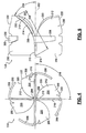
- FIG. 3 is an isometric view of an exemplary swirl element according to the principles of the present disclosure
- FIG. 4 is a front view of the swirl element shown in FIG. 3 ;
- FIG. 5 is a side view of the swirl element shown in FIG. 3 ;
- FIG. 6 is an exploded view of the swirl element shown in FIG. 3 .
- the engine and exhaust system 100 may include a diesel engine system 102 . While diesel engine system 102 is shown, the present disclosure is applicable to gasoline engine systems, homogeneous charge compression ignition engine systems, and/or other engine systems.
- the diesel engine system 102 includes an engine 104 and an exhaust system 106 .
- the engine 104 combusts a mixture of air and diesel fuel to produce power (e.g., torque).
- the combustion of the air and fuel mixture produces hot exhaust gas that may be expelled from the engine 104 into the exhaust system 106 .
- the hot exhaust gas produced by the engine 104 may contain a mixture of gaseous compounds and particulate matter that enters the exhaust system and may be treated therein prior to exiting the exhaust system 106 .
- the exhaust system 106 may include an exhaust manifold assembly 108 , an intermediate pipe assembly 110 , a particulate matter (PM) filter assembly 112 , and a muffler assembly 114 .
- the exhaust system 106 may also include an exhaust gas recirculation (EGR) assembly (not shown) that recirculates a portion of the exhaust gas back to the engine 104 .
- EGR exhaust gas recirculation
- the exhaust manifold assembly 108 , intermediate pipe assembly 110 , PM filter assembly 112 , and muffler assembly 114 may be coupled together by a series of flanged connections 116 or any other suitable method, such as by welding.
- Exhaust gas produced by the engine 104 flows through the exhaust manifold assembly 108 to the PM filter assembly 112 via the intermediate pipe assembly 110 .
- Exhaust gas exiting the PM filter assembly 112 flows through the muffler assembly 114 and is released to the atmosphere through a tailpipe 118 .
- the intermediate pipe assembly 110 may include exhaust gas after treatment systems, such as but not limited to, a diesel oxidation catalyst (DOC) assembly and a selective catalytic reduction (SCR) assembly.
- DOC assembly may be included to oxidize particulate matter such as hydrocarbons and/or carbon oxides in the exhaust gas.
- An SCR assembly may be included to inject ammonia or urea into the exhaust gas and thereby reduce the emission of NOx in the exhaust gas.
- the PM filter assembly 112 filters particulate matter from the exhaust gas flowing through the PM filter assembly 112 .
- Particulate matter may accumulate within the PM filter assembly 112 during a process referred to as loading and thereby restrict the flow of exhaust gas through the PM filter assembly 112 .
- Particulate matter that has accumulated within the PM filter assembly 112 may be removed by a process referred to as regeneration. During regeneration, heat carried by the exhaust gas is used to combust the particulate matter present in the PM filter assembly 112 .
- a discussion of a DPF assembly and the regeneration process can be found in commonly assigned U.S.
- the PM filter assembly 112 includes a housing 120 , a monolith filter assembly 122 , and a swirl element 124 .
- the housing 120 may include a center section 130 that contains the filter assembly 122 .
- the housing 120 may further include an inlet section 132 located adjacent an entry face 134 of the filter assembly 122 and an outlet section 136 located adjacent an exit face 138 of the filter assembly 122 .
- the inlet section 132 may be located upstream of the filter assembly 122 to fluidly connect the filter assembly 122 to the intermediate pipe assembly 110 .
- the inlet section 132 may include an inlet pipe 142 and an expansion pipe 144 .
- the inlet pipe 142 may deliver exhaust gas exiting the intermediate pipe assembly 110 to the expansion pipe 144 .
- the inlet pipe 142 may include a first end 146 coupled to the intermediate pipe assembly 110 via a flange 148 and a second end 150 extending into the expansion pipe 144 .
- the inlet pipe 142 may be generally straight as shown ( FIG. 2 ).
- the inlet pipe 142 may include a cylindrical inner wall 151 .
- the expansion pipe 144 may deliver exhaust gas exiting the inlet pipe 142 to the filter assembly 122 . More specifically, the expansion pipe 144 may deliver exhaust gas exiting the inlet pipe 142 to the entry face 134 of the filter assembly 122 .
- the second end 150 of the inlet pipe 142 may define an opening section 152 that has a cross-sectional area that is less than a frontal area 153 of the entry face 134 that confronts the exhaust gas.
- the expansion pipe 144 may include a narrow end 154 that receives the second end 150 of the inlet pipe 142 and a wide end 156 opposite the narrow end 154 that adjoins the entry face 134 of the filter assembly 122 .
- the expansion pipe 144 , inlet pipe 142 , and flange 148 may be secured together by any suitable means, including one or more welds 158 .
- the outlet section 136 may be located downstream of the filter assembly 122 to fluidly connect the filter assembly 122 to the muffler assembly 114 .
- the outlet section 136 section may include a reducer pipe 160 and an outlet pipe 162 .
- the reducer pipe 160 may deliver exhaust gas exiting the filter assembly 122 to the outlet pipe 162 .
- the reducer pipe 160 may include a first end 164 that adjoins the exit face 138 of the filter assembly 122 and a second end 166 opposite the first end 164 that is connected to the outlet pipe 162 .
- the first end 164 may be larger than the second end 166 as shown.
- the reducer pipe 160 and outlet pipe 162 may be integrally formed with the center section 130 .
- the outlet section 136 may further include a flange 168 that works together with the outlet pipe 162 to couple the PM filter assembly 112 to the muffler assembly 114 .
- the filter assembly 122 may include a filter substrate 170 that may define a series of honeycomb channels 172 that may extend from the entry face 134 to the exit face 138 . Each of the channels 172 may be sealed on one end by end plugs 174 such that a series of alternating inlets 180 and outlets 182 are formed thereby.
- the inlets 180 may be arranged in a generally uniform manner over the frontal area 153 of the entry face 134 .
- Exhaust gas may enter the filter assembly 122 and be forced through porous walls 184 of the filter substrate 170 before exiting the filter assembly 122 . Particulate matter in the exhaust gas may be trapped by the walls 184 and accumulate to form deposits 186 in the channels 172 .
- the walls 184 of the filter substrate 170 may be made of any material suitable for filtering particulate matter in the exhaust gas.
- the walls 184 may be made of a cordierite or silicon carbide material.
- the swirl element 124 may be disposed in the inlet pipe 142 at the second end 150 and may protrude into a cavity 188 formed by the expansion pipe 144 .
- the swirl element 124 may be positioned a distance 190 away from the entry face 134 of the filter assembly 122 .
- the swirl element 124 may separate a stream 192 of exhaust gas entering the PM filter assembly 112 into flow fields 194 .
- the swirl element 124 may lift and direct the flow fields 194 in a direction of flow that is different than the direction of flow of stream 192 .
- the swirl element 124 may direct the flow fields 194 outward in a direction away from the direction of flow of stream 192 towards the wide end 156 of expansion pipe 144 .
- the swirl element 124 also may direct the flow fields 194 in a manner that creates a spiral or rotational flow (i.e., vortex) of exhaust gas downstream of the swirl element 124 .
- the swirl element 124 may be used to more uniformly distribute heat and particulate matter contained in stream 192 over the entry face 134 of the filter assembly 122 .
- the swirl element 124 may be used to achieve a more even distribution of heat and soot (i.e., deposits 186 ) among the channels 172 during loading and regeneration.
- the swirl element 124 may be used to achieve improved distribution and mixing of other constituents of the exhaust gas, such as hydrocarbons and urea, that may be injected upstream of the swirl element into stream 192 .
- the swirl element 124 may be used to improve the efficiency of the PM filter assembly 112 .
- the swirl element 124 also may be used to manage peak temperatures within the filter substrate 170 and thereby improve the reliability of the PM filter assembly 112 .
- the swirl element 124 may include one or more blades 200 rotationally positioned about an axis 202 .
- the swirl element 124 may have four blades 200 as shown.
- the four blades 200 may be located at rotational positions about axis 202 ( FIG. 3 ).
- Each of the blades 200 may have generally the same size and shape and may be secured together by one or more fillet welds 204 .
- the swirl element 124 may further include one or more attachment tabs 206 that may be used to position and secure the swirl element 124 within the second end 150 of the inlet pipe 142 .
- axis 202 may extend in a direction substantially parallel to the inner wall 151 of inlet pipe 142 ( FIG. 2 ).
- substantially parallel means parallel within plus or minus ten degrees.
- the swirl element 124 may be positioned within the inlet pipe such that axis 202 extends in a direction that forms a desired angle (not shown) with the inner wall 151 .
- the angle between axis 202 and inner wall 151 may vary and may, for example, be between zero degrees and 75 degrees.
- Axis 202 may be located a distance away (i.e., offset) from the center of stream 192 .
- axis 202 may be located at the center of stream 192 as shown ( FIG. 2 ).
- the swirl element 124 may be positioned within the inlet pipe 142 such that axis 202 extends in a direction substantially parallel to the direction of flow of stream 192 as shown ( FIG. 2 ).
- the swirl element 124 may be positioned within the inlet pipe 142 such that axis 202 extends in a direction that forms a desired angle with the direction of flow of stream 192 .
- the direction of flow of stream 192 in the inlet pipe 142 may be understood by physical testing of the engine and exhaust system 100 , or by computer methods, such as computational fluid dynamics modeling.
- the inlet pipe 142 may work together with the expansion pipe 144 to position the swirl element 124 such that axis 202 , when projected, intersects the center of frontal area 153 . Put another way, the inlet pipe 142 and expansion pipe 144 may work together to align axis 202 and the center of frontal area 153 .
- the blades 200 may be thin, broad members that may include lead portions 210 and trailing portions 212 that extend from the lead portions 210 .
- the lead and trailing portions 210 , 212 may work together to provide major surfaces 214 of the blades 200 that receive a portion of stream 192 and lift and direct the resulting flow fields 194 .
- the lead portions 210 may be generally planar in shape and may extend in one direction between axis 202 and an inner wall 151 of the inlet pipe 142 (i.e., radially) and in another direction substantially parallel to axis 202 . In this manner, the lead portions 210 may be oriented substantially parallel to the flow of stream 192 .
- the lead portions 210 may include lead edges 216 that define included angles 218 between adjacent blades 200 .
- the lead edges 216 may be generally straight and may extend in a radial direction normal to axis 202 . Thus, the lead edges 216 may extend in a direction transverse to the direction of flow of stream 192 .
- the lead portions 210 may adjoin along axis 202 as shown ( FIG. 4 ).
- the trailing portions 212 may be generally curved in shape and may extend from the lead portions 210 in a direction away from axis 202 .
- the trailing portions 212 may include curved inner and outer trailing edges 220 , 222 that define departure angles 224 ( FIG. 5 ) with respect to axis 202 .
- the departure angles 224 may vary and may be, for example, between zero degrees and 75 degrees. More particularly, the departure angles 224 may be between 40 and 60 degrees. For example, departure angles 224 substantially equal to 45 degrees have been found to be suitable. As used herein, substantially equal angles are angles that are equal within plus or minus ten degrees.
- the departure angles 224 defined by the inner trailing edges 220 may be greater than the departure angles 224 defined by the outer trailing edges 222 . Put another way, the trailing portions 212 may be twisted about axis 202 such that the inner trailing edges 220 provide more lift to exhaust gas passing over the inner trailing edges 220 than the outer trailing edges 222 .
- the departure angles 224 defined by the inner and outer trailing edges 220 , 222 also may vary along their respective lengths.
- the blades 200 may include lead and trailing portions 210 , 212 as previously described, the trailing portions 212 may include the lead edges 216 .
- the blades 200 may include a single curved member (e.g., trailing portions 212 ).
- the trailing portions 212 are described as curved members, the trailing portions 212 may be generally planar in shape and may extend in a direction away from axis 202 as previously described.
- the blades 200 may be rotationally positioned in a symmetrical manner about axis 202 such that the included angles 218 between adjacent blades 200 are substantially equal ( FIG. 4 ). For example, where four blades are provided, the included angles 218 may be equal to about 90 degrees.
- the blades 200 also may be arranged such that the trailing portions 212 extend in the same rotational direction (e.g., clockwise or counterclockwise) about axis 202 as best seen in FIGS. 3-4 .
- the swirl element 124 may be used to create a spiral flow of exhaust gas downstream of the swirl element 124 (i.e., flow fields 194 ).
- the major surfaces 214 define frontal areas 226 ( FIG. 4 ) and chord lengths 228 ( FIG. 5 ).
- Features of the swirl element 124 such as, but not limited to, the frontal areas 226 , chord lengths 228 , and departure angles 224 may be chosen to achieve the desired directional flow of the flow fields 194 while minimizing back pressure in stream 192 . For example, where four blades 200 are provided and the departure angles 224 are equal to 45 degrees, pressure losses of less than two kilopascals have been achieved. Additionally, the swirl element 124 may be located within the PM filter assembly 112 to achieve the desired distribution of heat and particulate matter within the PM filter assembly 112 .
- the position of the swirl element 124 within the inlet pipe 142 and the distance 190 between the trailing portions 212 and the entry face 134 may be chosen to achieve the desired distribution of heat and particulate matter in the flow fields 194 to the entry face 134 .
- the attachment tabs 206 may protrude from the blades 200 in a normal direction and may include an outer surface 230 that slidably engages the inner wall 151 of the inlet pipe 142 .
- Each of the blades 200 may include a corresponding one of the attachment tabs 206 .
- the attachment tabs 206 may be secured to the second end 150 of the inlet pipe 142 by any suitable means.
- the attachment tabs 206 may be welded to the inlet pipe 142 . In this manner, the attachment tabs 206 may be used to fixedly position the blades 200 within the inlet pipe 142 .
- the swirl element 124 may include a pair of complementary members 240 , 242 .
- the members 240 , 242 may be stamped from any suitable sheet metal of suitable thickness.
- 409 stainless steel sheet metal having a thickness between 1.4 and 1.7 millimeters has been found to be suitable.
- 316 stainless steel sheet metal may be used where the exhaust system 106 includes a DOC assembly or SCR assembly that injects hydrocarbons or urea into the exhaust gas upstream of the swirl element (i.e., into stream 192 ).
- Each of the members 240 , 242 may include a pair of blades 200 coupled together by joining portions 244 , 246 .
- the joining portions 244 , 246 may work together with the blades 200 to define complementary slots 250 , 252 , respectively.
- the slots 250 , 252 may extend along axis 202 and may be sized to slidably engage one another. In this manner, the slots 250 , 252 may be used to slidably position the members 240 , 242 with respect to one another.
- the members 240 , 242 may be welded together at the joining portions 244 , 246 (e.g., welds 204 ).
- Each of the members 240 , 242 may further include a pair of attachment tabs 206 that extend from an outer edge the blades 200 in the same rotational direction when viewed along axis 202 (e.g., clockwise, counterclockwise).
- Each of the members 240 , 242 may include relief notches 260 , 262 adjacent the attachment tabs to facilitate the manufacture of the members 240 , 242 .
Abstract
Description
Claims (19)
Priority Applications (3)
| Application Number | Priority Date | Filing Date | Title |
|---|---|---|---|
| US12/251,734 US8043394B2 (en) | 2008-03-21 | 2008-10-15 | Particulate matter filter assembly with a flow device |
| DE102009012718.6A DE102009012718B4 (en) | 2008-03-21 | 2009-03-13 | Particulate material filter arrangement with a flow device and method for filtering particulate material |
| CN2009101268632A CN101539046B (en) | 2008-03-21 | 2009-03-20 | Particulate matter filter assembly with a flow device |
Applications Claiming Priority (2)
| Application Number | Priority Date | Filing Date | Title |
|---|---|---|---|
| US3850108P | 2008-03-21 | 2008-03-21 | |
| US12/251,734 US8043394B2 (en) | 2008-03-21 | 2008-10-15 | Particulate matter filter assembly with a flow device |
Publications (2)
| Publication Number | Publication Date |
|---|---|
| US20090235653A1 US20090235653A1 (en) | 2009-09-24 |
| US8043394B2 true US8043394B2 (en) | 2011-10-25 |
Family
ID=41087537
Family Applications (1)
| Application Number | Title | Priority Date | Filing Date |
|---|---|---|---|
| US12/251,734 Expired - Fee Related US8043394B2 (en) | 2008-03-21 | 2008-10-15 | Particulate matter filter assembly with a flow device |
Country Status (2)
| Country | Link |
|---|---|
| US (1) | US8043394B2 (en) |
| CN (1) | CN101539046B (en) |
Cited By (8)
| Publication number | Priority date | Publication date | Assignee | Title |
|---|---|---|---|---|
| US20090320453A1 (en) * | 2008-06-26 | 2009-12-31 | Gabriel Salanta | Exhaust gas additive/treatment system and mixer for use therein |
| US20130068097A1 (en) * | 2011-09-16 | 2013-03-21 | Lawrence Livermore National Security, Llc | Anti-clogging filter system |
| US20150047305A1 (en) * | 2011-12-16 | 2015-02-19 | Shell Oil Company B.V. | Separation device comprising a swirler |
| US20180361290A1 (en) * | 2015-12-17 | 2018-12-20 | Usui Co., Ltd. | Gas-liquid separator |
| US10473021B2 (en) * | 2016-11-29 | 2019-11-12 | Taiwan Semiconductor Manufacturing Company, Ltd. | Exhaust system and method of using |
| US10881996B2 (en) | 2015-12-17 | 2021-01-05 | Usui Co., Ltd. | Swirling flow generator for gas-liquid separation |
| US11179662B2 (en) * | 2016-12-08 | 2021-11-23 | Usui Co., Ltd | Gas-liquid separator |
| US11313330B2 (en) * | 2017-10-25 | 2022-04-26 | Usui Co., Ltd. | Gas-liquid separator |
Families Citing this family (20)
| Publication number | Priority date | Publication date | Assignee | Title |
|---|---|---|---|---|
| US8375709B2 (en) * | 2009-11-17 | 2013-02-19 | Tenneco Automotive Operating Company Inc. | Exhaust gas additive/treatment system and mixer for use therein |
| WO2011087527A1 (en) * | 2010-01-12 | 2011-07-21 | Donaldson Company, Inc. | Flow device for exhaust treatment system |
| US8273315B2 (en) * | 2010-08-09 | 2012-09-25 | Ford Global Technologies, Llc | Engine emission control system |
| US8756923B2 (en) | 2010-11-24 | 2014-06-24 | Cnh Industrial America Llc | Mixing pipe for SCR mufflers |
| CA2769913C (en) * | 2011-03-03 | 2013-09-24 | Toru Hisanaga | Exhaust heat recovery device |
| DE102011111765B4 (en) * | 2011-08-24 | 2023-06-22 | Friedrich Boysen Gmbh & Co. Kg | mixer device |
| WO2013087852A2 (en) * | 2011-12-14 | 2013-06-20 | Friedrich Boysen Gmbh & Co. Kg | Mixing apparatus |
| US8938954B2 (en) | 2012-04-19 | 2015-01-27 | Donaldson Company, Inc. | Integrated exhaust treatment device having compact configuration |
| GB201207201D0 (en) * | 2012-04-24 | 2012-06-06 | Perkins Engines Co Ltd | Emissions cleaning module for a diesel engine |
| US8793983B2 (en) | 2012-05-07 | 2014-08-05 | Electro-Motive Diesel, Inc. | Heater tube for an exhaust system |
| DE102014105836B4 (en) * | 2013-04-29 | 2023-02-23 | GM Global Technology Operations LLC (n. d. Ges. d. Staates Delaware) | Internal combustion engine with an exhaust aftertreatment system |
| CN105804835B (en) * | 2014-12-31 | 2018-11-27 | 骆旭东 | Environmentally friendly dynamic particle trapper |
| CN108343490A (en) * | 2018-02-06 | 2018-07-31 | 安徽江淮汽车集团股份有限公司 | A kind of automobile-used DPF device |
| CN108757124B (en) * | 2018-06-19 | 2023-08-29 | 中船发动机有限公司 | Selective catalytic reduction device suitable for marine diesel engine |
| US11274583B1 (en) * | 2019-11-05 | 2022-03-15 | Sonix Enterprises Inc. | Internal combustion engine exhaust modification system |
| US11591941B2 (en) | 2019-11-05 | 2023-02-28 | Sonix Enterprises Inc. | Internal combustion engine exhaust modification system |
| CN111946428B (en) * | 2020-07-14 | 2022-01-11 | 江苏大学 | DPF (diesel particulate filter) offline regeneration temperature control system and control method |
| CN112610306A (en) * | 2020-12-11 | 2021-04-06 | 安徽江淮汽车集团股份有限公司 | Gasoline engine particle filter |
| US11846423B2 (en) * | 2021-04-16 | 2023-12-19 | General Electric Company | Mixer assembly for gas turbine engine combustor |
| CN113244726B (en) * | 2021-05-12 | 2022-07-26 | 重庆鑫协环保设备有限公司 | Smoke waste gas treatment system for power battery test and treatment method thereof |
Citations (26)
| Publication number | Priority date | Publication date | Assignee | Title |
|---|---|---|---|---|
| US3448563A (en) * | 1966-09-19 | 1969-06-10 | North American Rockwell | Cyclone separator having substantially centrally located openings for lowering the pressure drop across the cyclone |
| US3964875A (en) | 1974-12-09 | 1976-06-22 | Corning Glass Works | Swirl exhaust gas flow distribution for catalytic conversion |
| US4999036A (en) * | 1990-04-26 | 1991-03-12 | Hwang Ming Y | Filtering device for removing liquid particles from air streams of air compressors |
| US5083435A (en) * | 1990-07-23 | 1992-01-28 | Lin Ching Chih | Exhaust pipe with turbine vane |
| JPH06212943A (en) * | 1993-01-16 | 1994-08-02 | Kubota Corp | Exhaust emission control device for engine |
| US5403367A (en) * | 1992-02-27 | 1995-04-04 | Atomic Energy Corporation Of South Africa Limited | Filtration |
| US5676717A (en) * | 1995-11-13 | 1997-10-14 | Ingersoll-Rand Company | Separator tank |
| US5678403A (en) * | 1994-10-12 | 1997-10-21 | Nippon Soken, Inc. | Adsorption apparatus for unburnt hydrocarbons for internal combustion engine |
| US5916134A (en) | 1997-09-10 | 1999-06-29 | Industrial Technology Research Institute | Catalytic converter provided with vortex generator |
| US6258144B1 (en) * | 1999-10-20 | 2001-07-10 | Jui-Fa Huang | Air filtering device for a vehicle engine including interengaged filter members and a flow regulation member |
| US6331195B1 (en) * | 1998-05-20 | 2001-12-18 | Alliedsignal Inc. | Coanda water extractor |
| US6540917B1 (en) * | 2000-11-10 | 2003-04-01 | Purolator Facet Inc. | Cyclonic inertial fluid cleaning apparatus |
| US6833023B1 (en) * | 2003-02-14 | 2004-12-21 | International Liner Co., Inc. | Air filter assembly |
| US20050056008A1 (en) * | 2003-09-10 | 2005-03-17 | O-Den Corporation | Particulate removing apparatus and diesel engine vehicle equipped with same |
| US7156889B1 (en) * | 2003-07-15 | 2007-01-02 | Astec, Inc. | Assembly for removing dust from gas stream |
| US7179315B2 (en) * | 2004-08-04 | 2007-02-20 | Jui-Fa Huang | Vertical-shaft air filtering device having high flow rate and two-way air intake structure |
| US20070062181A1 (en) | 2005-09-22 | 2007-03-22 | Williamson Weldon S | Diesel particulate filter (DPF) regeneration by electrical heating of resistive coatings |
| US20070125076A1 (en) * | 2005-12-06 | 2007-06-07 | Denso Corporation | Exhaust gas purifying apparatus for internal combustion engine |
| US20070144158A1 (en) | 2005-12-22 | 2007-06-28 | Girard James W | Exhaust dispersion device |
| US20070227109A1 (en) * | 2002-09-13 | 2007-10-04 | Ibiden Co., Ltd. | Filter |
| US20080087013A1 (en) * | 2004-01-13 | 2008-04-17 | Crawley Wilbur H | Swirl-Stabilized Burner for Thermal Management of Exhaust System and Associated Method |
| US20080110140A1 (en) * | 2006-11-13 | 2008-05-15 | Daniel Egger | Droplet separator |
| US20080127641A1 (en) * | 2005-12-14 | 2008-06-05 | Dolmar Gmbh | Exhaust system |
| US7491254B2 (en) * | 2002-04-04 | 2009-02-17 | Donaldson Company, Inc. | Filter elements; air cleaner; assembly; and, methods |
| US7533522B2 (en) * | 2005-09-02 | 2009-05-19 | Emitec Gesellschaft Fuer Emissionstechnologie Mbh | Method and apparatus for adding a reactant to an exhaust gas from an internal combustion engine |
| US7682413B2 (en) * | 2006-10-16 | 2010-03-23 | Deere & Company | Air precleaner arrangement for an internal combustion engine comprising two cyclone filters |
-
2008
- 2008-10-15 US US12/251,734 patent/US8043394B2/en not_active Expired - Fee Related
-
2009
- 2009-03-20 CN CN2009101268632A patent/CN101539046B/en not_active Expired - Fee Related
Patent Citations (26)
| Publication number | Priority date | Publication date | Assignee | Title |
|---|---|---|---|---|
| US3448563A (en) * | 1966-09-19 | 1969-06-10 | North American Rockwell | Cyclone separator having substantially centrally located openings for lowering the pressure drop across the cyclone |
| US3964875A (en) | 1974-12-09 | 1976-06-22 | Corning Glass Works | Swirl exhaust gas flow distribution for catalytic conversion |
| US4999036A (en) * | 1990-04-26 | 1991-03-12 | Hwang Ming Y | Filtering device for removing liquid particles from air streams of air compressors |
| US5083435A (en) * | 1990-07-23 | 1992-01-28 | Lin Ching Chih | Exhaust pipe with turbine vane |
| US5403367A (en) * | 1992-02-27 | 1995-04-04 | Atomic Energy Corporation Of South Africa Limited | Filtration |
| JPH06212943A (en) * | 1993-01-16 | 1994-08-02 | Kubota Corp | Exhaust emission control device for engine |
| US5678403A (en) * | 1994-10-12 | 1997-10-21 | Nippon Soken, Inc. | Adsorption apparatus for unburnt hydrocarbons for internal combustion engine |
| US5676717A (en) * | 1995-11-13 | 1997-10-14 | Ingersoll-Rand Company | Separator tank |
| US5916134A (en) | 1997-09-10 | 1999-06-29 | Industrial Technology Research Institute | Catalytic converter provided with vortex generator |
| US6331195B1 (en) * | 1998-05-20 | 2001-12-18 | Alliedsignal Inc. | Coanda water extractor |
| US6258144B1 (en) * | 1999-10-20 | 2001-07-10 | Jui-Fa Huang | Air filtering device for a vehicle engine including interengaged filter members and a flow regulation member |
| US6540917B1 (en) * | 2000-11-10 | 2003-04-01 | Purolator Facet Inc. | Cyclonic inertial fluid cleaning apparatus |
| US7491254B2 (en) * | 2002-04-04 | 2009-02-17 | Donaldson Company, Inc. | Filter elements; air cleaner; assembly; and, methods |
| US20070227109A1 (en) * | 2002-09-13 | 2007-10-04 | Ibiden Co., Ltd. | Filter |
| US6833023B1 (en) * | 2003-02-14 | 2004-12-21 | International Liner Co., Inc. | Air filter assembly |
| US7156889B1 (en) * | 2003-07-15 | 2007-01-02 | Astec, Inc. | Assembly for removing dust from gas stream |
| US20050056008A1 (en) * | 2003-09-10 | 2005-03-17 | O-Den Corporation | Particulate removing apparatus and diesel engine vehicle equipped with same |
| US20080087013A1 (en) * | 2004-01-13 | 2008-04-17 | Crawley Wilbur H | Swirl-Stabilized Burner for Thermal Management of Exhaust System and Associated Method |
| US7179315B2 (en) * | 2004-08-04 | 2007-02-20 | Jui-Fa Huang | Vertical-shaft air filtering device having high flow rate and two-way air intake structure |
| US7533522B2 (en) * | 2005-09-02 | 2009-05-19 | Emitec Gesellschaft Fuer Emissionstechnologie Mbh | Method and apparatus for adding a reactant to an exhaust gas from an internal combustion engine |
| US20070062181A1 (en) | 2005-09-22 | 2007-03-22 | Williamson Weldon S | Diesel particulate filter (DPF) regeneration by electrical heating of resistive coatings |
| US20070125076A1 (en) * | 2005-12-06 | 2007-06-07 | Denso Corporation | Exhaust gas purifying apparatus for internal combustion engine |
| US20080127641A1 (en) * | 2005-12-14 | 2008-06-05 | Dolmar Gmbh | Exhaust system |
| US20070144158A1 (en) | 2005-12-22 | 2007-06-28 | Girard James W | Exhaust dispersion device |
| US7682413B2 (en) * | 2006-10-16 | 2010-03-23 | Deere & Company | Air precleaner arrangement for an internal combustion engine comprising two cyclone filters |
| US20080110140A1 (en) * | 2006-11-13 | 2008-05-15 | Daniel Egger | Droplet separator |
Non-Patent Citations (1)
| Title |
|---|
| Translation of JP 06212943 A, Aug. 1994, 7 pages. * |
Cited By (14)
| Publication number | Priority date | Publication date | Assignee | Title |
|---|---|---|---|---|
| US8397495B2 (en) | 2008-06-26 | 2013-03-19 | Tenneco Automotive Operating Company Inc. | Exhaust gas additive/treatment system and mixer for use therein |
| US20090320453A1 (en) * | 2008-06-26 | 2009-12-31 | Gabriel Salanta | Exhaust gas additive/treatment system and mixer for use therein |
| US20130068097A1 (en) * | 2011-09-16 | 2013-03-21 | Lawrence Livermore National Security, Llc | Anti-clogging filter system |
| US9034066B2 (en) * | 2011-09-16 | 2015-05-19 | Lawrence Livermore National Security, Llc | Anti-clogging filter system |
| US9630137B2 (en) | 2011-09-16 | 2017-04-25 | Lawrence Livermore National Security, Llc | Anti-clogging filter system |
| US10427172B2 (en) * | 2011-12-16 | 2019-10-01 | Shell Oil Company | Separation device comprising a swirler |
| US20150047305A1 (en) * | 2011-12-16 | 2015-02-19 | Shell Oil Company B.V. | Separation device comprising a swirler |
| US20180361290A1 (en) * | 2015-12-17 | 2018-12-20 | Usui Co., Ltd. | Gas-liquid separator |
| US10828590B2 (en) * | 2015-12-17 | 2020-11-10 | Usui Co., Ltd. | Gas-liquid separator |
| US10881996B2 (en) | 2015-12-17 | 2021-01-05 | Usui Co., Ltd. | Swirling flow generator for gas-liquid separation |
| US10473021B2 (en) * | 2016-11-29 | 2019-11-12 | Taiwan Semiconductor Manufacturing Company, Ltd. | Exhaust system and method of using |
| US11022018B2 (en) * | 2016-11-29 | 2021-06-01 | Taiwan Semiconductor Manufacturing Company, Ltd. | Exhaust system and method of using |
| US11179662B2 (en) * | 2016-12-08 | 2021-11-23 | Usui Co., Ltd | Gas-liquid separator |
| US11313330B2 (en) * | 2017-10-25 | 2022-04-26 | Usui Co., Ltd. | Gas-liquid separator |
Also Published As
| Publication number | Publication date |
|---|---|
| CN101539046B (en) | 2012-09-19 |
| CN101539046A (en) | 2009-09-23 |
| US20090235653A1 (en) | 2009-09-24 |
Similar Documents
| Publication | Publication Date | Title |
|---|---|---|
| US8043394B2 (en) | Particulate matter filter assembly with a flow device | |
| US9810126B2 (en) | Flow device for exhaust treatment system | |
| EP2578828B1 (en) | Exhaust gas purification device | |
| EP2841732B1 (en) | Exhaust mixer, emissions cleaning module and method | |
| US9957866B2 (en) | Exhaust treatment apparatus and method | |
| US7757484B2 (en) | Exhaust treatment device having flow-promoting end caps | |
| JP2010513773A (en) | Mixing system for fluid injection and exhaust aftertreatment devices | |
| US9879581B2 (en) | After-treatment system | |
| CN114622972B (en) | Internal cyclone tube for exhaust catalyst | |
| US20160194995A1 (en) | Flow mixing device for an exhaust after-treatment system | |
| WO2017170108A1 (en) | Exhaust purification system | |
| JP2016188579A (en) | Exhaust emission control unit | |
| US20070122319A1 (en) | Particulate filter | |
| CN114522537A (en) | Flow diverter for high efficiency mixer | |
| US10941692B1 (en) | Mixer assembly for exhaust aftertreatment system | |
| CN111742122B (en) | Reducing agent injection device | |
| JP2016205188A (en) | Exhaust emission control unit | |
| KR101283507B1 (en) | Apparatus for mixing reducing agent of scr system | |
| DE102009012718B4 (en) | Particulate material filter arrangement with a flow device and method for filtering particulate material | |
| KR20050060779A (en) | Structure for improving diffusivity in exchaust gas after-treatment apparatus | |
| JP2012002084A (en) | Guide for guiding exhaust flow, and exhaust emission control device equipped with the same |
Legal Events
| Date | Code | Title | Description |
|---|---|---|---|
| AS | Assignment |
Owner name: GM GLOBAL TECHNOLOGY OPERATIONS, INC., MICHIGAN Free format text: ASSIGNMENT OF ASSIGNORS INTEREST;ASSIGNORS:MITAL, RAHUL;BROWN, DAVID B.;LI, JIANWEN;AND OTHERS;REEL/FRAME:021684/0750;SIGNING DATES FROM 20080922 TO 20081005 Owner name: GM GLOBAL TECHNOLOGY OPERATIONS, INC., MICHIGAN Free format text: ASSIGNMENT OF ASSIGNORS INTEREST;ASSIGNORS:MITAL, RAHUL;BROWN, DAVID B.;LI, JIANWEN;AND OTHERS;SIGNING DATES FROM 20080922 TO 20081005;REEL/FRAME:021684/0750 |
|
| AS | Assignment |
Owner name: UNITED STATES DEPARTMENT OF THE TREASURY,DISTRICT Free format text: SECURITY AGREEMENT;ASSIGNOR:GM GLOBAL TECHNOLOGY OPERATIONS, INC.;REEL/FRAME:022201/0405 Effective date: 20081231 Owner name: UNITED STATES DEPARTMENT OF THE TREASURY, DISTRICT Free format text: SECURITY AGREEMENT;ASSIGNOR:GM GLOBAL TECHNOLOGY OPERATIONS, INC.;REEL/FRAME:022201/0405 Effective date: 20081231 |
|
| AS | Assignment |
Owner name: CITICORP USA, INC. AS AGENT FOR BANK PRIORITY SECU Free format text: SECURITY AGREEMENT;ASSIGNOR:GM GLOBAL TECHNOLOGY OPERATIONS, INC.;REEL/FRAME:022554/0538 Effective date: 20090409 Owner name: CITICORP USA, INC. AS AGENT FOR HEDGE PRIORITY SEC Free format text: SECURITY AGREEMENT;ASSIGNOR:GM GLOBAL TECHNOLOGY OPERATIONS, INC.;REEL/FRAME:022554/0538 Effective date: 20090409 |
|
| AS | Assignment |
Owner name: GM GLOBAL TECHNOLOGY OPERATIONS, INC., MICHIGAN Free format text: RELEASE BY SECURED PARTY;ASSIGNOR:UNITED STATES DEPARTMENT OF THE TREASURY;REEL/FRAME:023126/0914 Effective date: 20090709 Owner name: GM GLOBAL TECHNOLOGY OPERATIONS, INC., MICHIGAN Free format text: RELEASE BY SECURED PARTY;ASSIGNORS:CITICORP USA, INC. AS AGENT FOR BANK PRIORITY SECURED PARTIES;CITICORP USA, INC. AS AGENT FOR HEDGE PRIORITY SECURED PARTIES;REEL/FRAME:023155/0769 Effective date: 20090814 Owner name: GM GLOBAL TECHNOLOGY OPERATIONS, INC.,MICHIGAN Free format text: RELEASE BY SECURED PARTY;ASSIGNOR:UNITED STATES DEPARTMENT OF THE TREASURY;REEL/FRAME:023126/0914 Effective date: 20090709 Owner name: GM GLOBAL TECHNOLOGY OPERATIONS, INC.,MICHIGAN Free format text: RELEASE BY SECURED PARTY;ASSIGNORS:CITICORP USA, INC. AS AGENT FOR BANK PRIORITY SECURED PARTIES;CITICORP USA, INC. AS AGENT FOR HEDGE PRIORITY SECURED PARTIES;REEL/FRAME:023155/0769 Effective date: 20090814 |
|
| AS | Assignment |
Owner name: UNITED STATES DEPARTMENT OF THE TREASURY, DISTRICT Free format text: SECURITY AGREEMENT;ASSIGNOR:GM GLOBAL TECHNOLOGY OPERATIONS, INC.;REEL/FRAME:023156/0313 Effective date: 20090710 Owner name: UNITED STATES DEPARTMENT OF THE TREASURY,DISTRICT Free format text: SECURITY AGREEMENT;ASSIGNOR:GM GLOBAL TECHNOLOGY OPERATIONS, INC.;REEL/FRAME:023156/0313 Effective date: 20090710 |
|
| AS | Assignment |
Owner name: UAW RETIREE MEDICAL BENEFITS TRUST, MICHIGAN Free format text: SECURITY AGREEMENT;ASSIGNOR:GM GLOBAL TECHNOLOGY OPERATIONS, INC.;REEL/FRAME:023162/0237 Effective date: 20090710 Owner name: UAW RETIREE MEDICAL BENEFITS TRUST,MICHIGAN Free format text: SECURITY AGREEMENT;ASSIGNOR:GM GLOBAL TECHNOLOGY OPERATIONS, INC.;REEL/FRAME:023162/0237 Effective date: 20090710 |
|
| AS | Assignment |
Owner name: GM GLOBAL TECHNOLOGY OPERATIONS, INC., MICHIGAN Free format text: RELEASE BY SECURED PARTY;ASSIGNOR:UNITED STATES DEPARTMENT OF THE TREASURY;REEL/FRAME:025245/0909 Effective date: 20100420 |
|
| AS | Assignment |
Owner name: GM GLOBAL TECHNOLOGY OPERATIONS, INC., MICHIGAN Free format text: RELEASE BY SECURED PARTY;ASSIGNOR:UAW RETIREE MEDICAL BENEFITS TRUST;REEL/FRAME:025315/0046 Effective date: 20101026 |
|
| AS | Assignment |
Owner name: WILMINGTON TRUST COMPANY, DELAWARE Free format text: SECURITY AGREEMENT;ASSIGNOR:GM GLOBAL TECHNOLOGY OPERATIONS, INC.;REEL/FRAME:025324/0515 Effective date: 20101027 |
|
| AS | Assignment |
Owner name: GM GLOBAL TECHNOLOGY OPERATIONS LLC, MICHIGAN Free format text: CHANGE OF NAME;ASSIGNOR:GM GLOBAL TECHNOLOGY OPERATIONS, INC.;REEL/FRAME:025781/0245 Effective date: 20101202 |
|
| STCF | Information on status: patent grant |
Free format text: PATENTED CASE |
|
| FEPP | Fee payment procedure |
Free format text: PAYOR NUMBER ASSIGNED (ORIGINAL EVENT CODE: ASPN); ENTITY STATUS OF PATENT OWNER: LARGE ENTITY |
|
| AS | Assignment |
Owner name: GM GLOBAL TECHNOLOGY OPERATIONS LLC, MICHIGAN Free format text: RELEASE BY SECURED PARTY;ASSIGNOR:WILMINGTON TRUST COMPANY;REEL/FRAME:034384/0758 Effective date: 20141017 |
|
| FPAY | Fee payment |
Year of fee payment: 4 |
|
| FEPP | Fee payment procedure |
Free format text: MAINTENANCE FEE REMINDER MAILED (ORIGINAL EVENT CODE: REM.); ENTITY STATUS OF PATENT OWNER: LARGE ENTITY |
|
| LAPS | Lapse for failure to pay maintenance fees |
Free format text: PATENT EXPIRED FOR FAILURE TO PAY MAINTENANCE FEES (ORIGINAL EVENT CODE: EXP.); ENTITY STATUS OF PATENT OWNER: LARGE ENTITY |
|
| STCH | Information on status: patent discontinuation |
Free format text: PATENT EXPIRED DUE TO NONPAYMENT OF MAINTENANCE FEES UNDER 37 CFR 1.362 |
|
| FP | Lapsed due to failure to pay maintenance fee |
Effective date: 20191025 |