US8046097B2 - Region-based supports for parts produced by solid freeform fabrication - Google Patents
Region-based supports for parts produced by solid freeform fabrication Download PDFInfo
- Publication number
- US8046097B2 US8046097B2 US12/212,242 US21224208A US8046097B2 US 8046097 B2 US8046097 B2 US 8046097B2 US 21224208 A US21224208 A US 21224208A US 8046097 B2 US8046097 B2 US 8046097B2
- Authority
- US
- United States
- Prior art keywords
- support
- pixels
- supports
- region
- accordance
- Prior art date
- Legal status (The legal status is an assumption and is not a legal conclusion. Google has not performed a legal analysis and makes no representation as to the accuracy of the status listed.)
- Active, expires
Links
Images


Classifications
-
- B—PERFORMING OPERATIONS; TRANSPORTING
- B29—WORKING OF PLASTICS; WORKING OF SUBSTANCES IN A PLASTIC STATE IN GENERAL
- B29C—SHAPING OR JOINING OF PLASTICS; SHAPING OF MATERIAL IN A PLASTIC STATE, NOT OTHERWISE PROVIDED FOR; AFTER-TREATMENT OF THE SHAPED PRODUCTS, e.g. REPAIRING
- B29C64/00—Additive manufacturing, i.e. manufacturing of three-dimensional [3D] objects by additive deposition, additive agglomeration or additive layering, e.g. by 3D printing, stereolithography or selective laser sintering
- B29C64/40—Structures for supporting 3D objects during manufacture and intended to be sacrificed after completion thereof
-
- B—PERFORMING OPERATIONS; TRANSPORTING
- B33—ADDITIVE MANUFACTURING TECHNOLOGY
- B33Y—ADDITIVE MANUFACTURING, i.e. MANUFACTURING OF THREE-DIMENSIONAL [3-D] OBJECTS BY ADDITIVE DEPOSITION, ADDITIVE AGGLOMERATION OR ADDITIVE LAYERING, e.g. BY 3-D PRINTING, STEREOLITHOGRAPHY OR SELECTIVE LASER SINTERING
- B33Y50/00—Data acquisition or data processing for additive manufacturing
- B33Y50/02—Data acquisition or data processing for additive manufacturing for controlling or regulating additive manufacturing processes
Definitions
- the present invention is related to the creation of three dimensional parts produced by solid freeform fabrication, and more particularly, to the generation of supports for the parts produced by solid freeform fabrication.
- SFF Solid Freeform Fabrication techniques
- Some SFF techniques include stereolithography, selective deposition modeling, laminated object manufacturing, selective phase area deposition, multi-phase jet solidification, ballistic particle manufacturing, fused deposition modeling, particle deposition, laser sintering, film transfer imaging, and the like.
- complex parts are produced from a build material in an additive fashion as opposed to conventional fabrication techniques, which are generally subtractive in nature. For example, in most conventional fabrication techniques material is removed by machining operations or shaped in a die or mold to near net shape and then trimmed.
- SFF technologies typically utilize a computer graphic representation of a part and a supply of a build material to fabricate the part in successive layers.
- SFF technologies have many advantages over conventional manufacturing methods. For instance, SFF technologies dramatically shorten the time to develop prototype parts and can produce limited numbers of parts in rapid manufacturing methods. They also eliminate the need for complex tooling and machining associated with conventional subtractive manufacturing methods, including the need to create molds for custom applications. In addition, customized parts can be directly produced from computer graphic data (e.g., computer-aided design (CAD) files) in SFF techniques.
- CAD computer-aided design
- structures are formed in a layer by layer manner by solidifying or curing successive layers of a build material.
- a tightly focused beam of energy typically in the ultraviolet radiation band
- a tightly focused beam of energy is scanned across sequential layers of a liquid photopolymer resin to selectively cure resin of each layer to form a multilayered part.
- selective laser sintering a tightly focused beam of energy, such as a laser beam, is scanned across sequential layers of powder material to selectively sinter or melt powder in each layer to form a multilayered part.
- a build material is jetted or dropped in discrete droplets, or extruded through a nozzle, such that the build material becomes relatively rigid upon a change in temperature and/or exposure to actinic radiation in order to build up a three-dimensional part in a layerwise fashion.
- FTI film transfer imaging
- the present invention comprises various methods for producing supports for parts produced by SFF.
- the present invention also comprises supports (also known as “support structures”) having various shapes, sizes, positions, and other properties.
- supports also known as “support structures” having various shapes, sizes, positions, and other properties.
- One exemplary embodiment comprises supports for FTI systems, in which parts are often produced upside down with supports between the part and build pad, thus requiring relatively strong supports to keep the part attached to the build pad despite relatively high removal forces that are exerted upon the part as it separates from the image plane, film surface, or other surface.
- Still further embodiments provide methods of forming improved supports for alternative SFF techniques such as stereolithography and selective deposition modeling, to provide two non-limiting examples.
- One aspect of the present invention is directed to a method of generating support structures for a three-dimensional part formed using SFF.
- the method includes slicing stereolithography (STL) models to generate part voxels; creating two-dimensional layer data and pixel data from the part voxels; applying compensation or correction on STL to correct imaging errors and to correctly position the borders using pixel blending; determining support anchors; creating support voxels; and generating the support structures for the pixel representation of the original STL model.
- STL stereolithography
- FIG. 1 is a schematic plan diagram of two parts—namely, a teapot base and a showerhead—as formed on a build pad, and showing the supports used for each part;
- FIG. 2 is a perspective view of the built teapot base and the shower head on the build pad and showing the supports used to support the parts;
- FIG. 3 is a schematic X-Z diagram of an example p art to be built, illustrating the “Probables” pixels PP;
- FIG. 4 is a X-Y schematic diagram of the top-most layer of the part of an example part to be built, showing the starting-point pixel P 1 ;
- FIG. 5 is a schematic X-Y diagram similar to FIG. 4 , showing the inclusion of additional pixels in defining region R for the given layer L;
- FIG. 6 is similar to FIG. 5 , and shows the inclusion of even more additional pixels in defining region R;
- FIG. 7 is similar to FIG. 6 , and shows region R 1 as being completely identified;
- FIG. 8 is a X-Y schematic diagram of a part showing the outer pixels PO;
- FIG. 9 is a X-Y schematic diagram of a part showing both inner and outer pixels PI and PO for a select layer of an object
- FIG. 10 and FIG. 11 are schematic diagrams of an example layer of an object illustrating the identification of self-supporting pixels by “insetting” select pixels in the region;
- FIG. 12 is a perspective view of an example part that includes a self-supporting area as determined by the “insetting” method illustrated in FIGS. 10 and 11 ;
- FIG. 13 is an example X-Y view of a region of interest R for an example object
- FIG. 14 is a X-Z view of the region of interest of FIG. 13 showing a flat top and two steep walls;
- FIG. 15 is a X-Z schematic diagram of an example part relative to a build pad and showing the boundaries and edges of the part;
- FIG. 16 is a X-Z schematic diagram similar to FIG. 15 , showing the Zmin and Zmax values for the region;
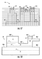
- FIG. 17 is a schematic X-Z diagram of an example part that includes a number of “islands” and a bridge-type structure;
- FIG. 18 is similar to FIG. 17 and shows the identification of five different island features
- FIG. 19 is an example of a largest cross-section of a layer to be supported by support structures
- FIG. 20 is similar to FIG. 19 , but that shows surface supports that lie within the part cross-section.
- FIG. 21A shows an example schematic side view of an example part supported by a prior art support structure, illustrating a support structure with too few supports;
- FIG. 21B is similar to FIG. 21A , except that the part is supported by too many supports;
- FIG. 22 is a schematic diagram of an example part wherein the support is calculated in a manner according to the prior art that results in a mismatch between the support and the part;
- FIG. 23 is a flowchart of an example method of creating supports that uses sliced data, voxels and pixels;
- FIG. 24 is a schematic diagram of a part in the X-Z plane along with the build pad, illustrating the different types of voxels used to describe the part;
- FIG. 25 is a schematic diagram similar to FIG. 24 , illustrating the construction of support voxels at support anchors in the part;
- FIG. 26A is a perspective view and FIG. 26B is a side view of an example part or “STL model”, indicating in FIG. 26B a “current layer” and a “previous layer” that denote current and previously processed layers;
- FIG. 27 is a pictorial flow diagram that illustrates an example method of constructing support voxels from part voxels
- FIG. 28 is a close-up view of a portion of a part that illustrates the step of applying a Z-compensation by moving down-facing voxels by a certain compensating distance to compensate for overcure;
- FIG. 29 is a schematic diagram of a support grid pattern
- FIG. 30 is a schematic diagram of a part and a build pad showing an example of forming a support having a base section, a long section and a tip section, along with the corresponding support anchors represented by down-facing and up-facing support voxels;
- FIG. 31A through FIG. 31D are cross-sectional views of various support patterns along the Z-direction for a grid of 32 ⁇ 32 pixels;
- FIG. 34 is a schematic diagram of a set of multi-pixel support anchors
- FIG. 36 is a schematic cross-sectional diagram of a typical reinforcement pattern between support posts in the long section of the support
- FIG. 37 is a schematic close-up diagram of a part being built, showing various configurations of the supports, including non-anchor support tips;
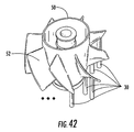
- FIG. 41 is a Y-Z cross-sectional view of the fan part of FIG. 38 along with the pattern of supports.
- One exemplary SFF system considered herein is an FTI system, such as the V-FLASH Desktop Modeler offered by 3D Systems, Inc. of Rock Hill, S.C., the assignee of the present application.
- FTI systems are described in one or more of U.S. Patent Application Publication Numbers; 2007/0259066; 2006/0249884; 2007/0296854; 2008/0206383; 2008/0169589; and 2008/0179786 which are assigned to the assignee of the present application, and the disclosures of which are incorporated by reference herein in their entirety.
- the portion of a part underlying a local maximum is described as a region.
- the portion of interest of each region is the size at its largest cross-section.
- any layer built completely on top of another layer is self supporting, but in addition the new layer can extend sideways substantially beyond the old layer and the old layer will still support it.
- the extent of the ability of a layer to be self-supporting can be determined. This typically can be from 10 to 50 or more pixels. Parts with steep walls tend to be completely self supporting. Parts with shallower walls will need to have additional supports along the wall, depending on the resin type and the build conditions. Flat areas require supports spaced over the entire flat area. As additional supports are employed, their strength is added when calculating whether the supports are strong enough not to break as the part is pulled away from the largest cross-section of each region and sub-region.
- the strength (load) requirement to pull parts away from the coater film (or image plane) can be substantial, and green supports tend not to be sufficiently strong.
- the breaking force required for a large cross-section support can exceed 50 pounds (222 N), while the breaking strength of a typical 4 ⁇ 4 pixel support is around 6 pounds (27 N).
- the load requirement is a few pounds. Regardless of the load requirements to pull parts away from the coater, the supports need to be sufficiently strong and the number of supports should be minimized.
- the present invention provides numerous advantages to users of the SFF system compared to prior art supports. Some of these advantages include, but are not limited to: 1) the part is assured to be built without the supports breaking; 2) the number of scars is minimized for easy post-processing; 3) there is no build-time penalty for forming the fewer number of supports (the exposure time equals the layer exposure time plus the border exposure time); and 4) less resin is used for the supports than in prior art support configurations, which translates into a lower operating cost for the SFF system being used to build the part.
- the following description provides a number of example methods of formulating different regions using pixel layer data generated for a FTI system. These regions are then used for the support generation method. It should be appreciated that the actual support generation method may be performed by any present or future method for generating supports, including, but not limited to the methods described in the above mentioned patents incorporated by reference.
- the support generation methods of the present invention are based upon the following assumptions: 1) A single region that requires support can span across multiple layers; 2) a single layer can have multiple regions that require support; 3) vertical scarring of parts due to the supports needs to be minimized; 4) support regions should include outer edges and corners of a part so as to prevent delimitation of layers; and 5) the support regions created should account for steep regions that are self-supporting, i.e., self-supporting steep portions of the part should be identified and eliminated from the support regions.
- the first main aspect of the support generation method is to independently identify part regions (“support regions” or just “regions”) in at least one layer, and preferably each layer, in the part building method that require support. This involves analyzing the layers independently using seven steps (steps 1 to 7 , below) to generate regions R for each layer. During the first six steps, the formation of each region R is restricted to a single layer. The seven steps of the method are discussed with reference to FIG. 3 through FIG. 7 .
- FIG. 3 is a schematic X-Z diagram of an example part 50 to be built.
- Part 50 is broken down into a number of basic part components (“pixels”) P and layers L (L 1 , L 2 , . . . L 3 ).
- Step 1 includes identifying all the pixels P that are open to air and that face upward.
- This entire set of pixels, which are shaded in light gray and identified as pixel set PP in FIG. 3 is referred to as “PROBABLES.”
- This is the total set of pixels P that will be analyzed and can be part of a region R.
- the pixels P that are not part of this set PP cannot be part of any region.
- pixels in pixel set PP have a chance (i.e., a probability) of being considered as part of a region R.
- step 2 one starts with the layer L 1 and the lower-left pixel that belongs to PROBABLES pixel set PP.
- This pixel is identified as pixel P 1 and is used as the starting point to identify regions.
- FIG. 4 is a schematic diagram of the top-most layer of a part 50 to be built. It is noted here that any useful notation can be used for pixel identification, such as P(X,Y,Z), where X,Y,Z are Cartesian coordinates that represent the center-point coordinates of the particular pixel.
- pixel P 1 is identified (“tagged”) as “region 1 ” or R 1 , as shown in FIG. 4 .
- step 3 all the pixels P that belong to the PROBABLES pixel set PP and that neighbor the pixel P 1 identified in step 2 are identified and included in Region R 1 .
- FIG. 5 is similar to FIG. 4 and illustrates the additional pixels P 2 , P 3 and P 4 added to region R 1 , so that region R 1 now includes a total of four pixels P 1 through P 4 (“P 1 -P 4 ”).
- step 4 all of the neighboring pixels of the pixels P 1 -P 4 presently in Region R 1 are identified.
- FIG. 6 is similar to FIG. 5 and shows pixels P 5 through P 10 as the neighboring pixels. If any of these newly identified pixels P 5 through P 10 belong to the set “PROBABLES” PP, then they are also included in region R 1 .
- Step 5 repeats step 4 and grows region R 1 until none of the neighboring pixels P of region R 1 belong to the set PROBABLES PP. At this point region R 1 has been completely identified, as illustrated in FIG. 7 .
- regions R will only have outer boundaries, while some will have inner and outer boundaries. Examples of these two cases are presented in the schematic diagrams of FIG. 8 and FIG. 9 , respectively.
- the outer-boundary pixels PO and the inner-boundary pixels PI are tagged separately.
- Step 6 includes determining if there are any other “PROBABLES” PP left on layer L 1 that are not part of region R 1 . If so, among the remaining “PROBABLES” pixels in layer R 1 , start with the lower-left pixel and repeat the method used to determine the next region R 2 . This method is repeated until all the PROBABLES on layer L 1 have been exhausted.
- Step 7 involves repeating steps 1 through 6 for each layer L that makes up part 50 in order to identify all of the regions R.
- the second main aspect of the support generation method involves eliminating any self-supporting pixels P in each region R. This will also eliminate from each region R those pixels P where if supports 30 are created, they will cause scarring on neighboring vertical walls.
- Step 8 includes considering the pixels P that are on the outer boundary of the region R to determine if any of these pixels have immediate neighboring pixels that are not part of region. If so, those outer boundary pixels P are marked as “self-supporting pixels” PS and only the pixels P that have the neighboring pixels by a width of 1 pixel P are inset.
- FIG. 10 and FIG. 11 are schematic diagrams of an example layer L of an object 50 illustrating this method.
- the direction of inset is 180 degrees opposite from the self-supporting pixels PS.
- FIG. 12 is a perspective view of an object 50 that illustrates a self-supporting area SSA determined after the above insetting method.
- the outer boundary adjacent the self-supporting pixels PS was pushed inside by “one pixel width.”
- the outer boundary can be pushed in by a distance of 2 or 3 pixel widths.
- the exact self-supporting distance is determined empirically in accordance with further embodiments of the present invention.
- region R is very thin (e.g., such as 3 pixels wide), and one edge is self-supporting, then the outer edge of the region R is preferably not purged because it needs to be supported to prevent delamination.
- the entire region R comprises just a few pixels P (e.g., 4 to 5), then it can be identified as “a small feature” can be designated to be supported by a single support 30 .
- Step 8 is carried out region by region until all of the regions R have been considered.
- the third main aspect of the support generation method involves identifying and eliminating any self-supporting steep areas from the identified regions R. This serves to minimize the number of supports 30 by not supporting those regions that do not need support.
- What constitutes a “steep” area depends on a number of factors, including the type of material used and the particular build method parameters involved in forming part 50 .
- a “self-supporting angle” is empirically determined for the particular type of build method used.
- Step 9 of the method thus involves performing an analysis that seeks to identify those sections within a region that need support, including eliminating entire regions if they are deemed self-supporting.
- FIG. 13 is an X-Y view of the region R of interest.
- FIG. 14 is the Z-view (i.e., the view in the X-Z plane) of the same region.
- the steep sections R ST of region R are sufficiently steep so that they are deemed self-supporting, so that the pixels P associated therewith should be eliminated from the region R once the analysis is complete.
- One example approach to identifying steep region sections R ST within a region R is as follows. First, start with the top-most region R (i.e., the region closest to build pad BP.) then independently consider each row of X-pixels P for the given region R. For the part illustrated in FIGS. 13 and 14 , consider a row of pixels P located in the middle of the region R.
- the pixels are X-tagged and Y-tagged as set forth in the following Table 1:
- each pixel P will have an X- and a Y-direction tag. If either of these direction tags is “STEEP,” the particular pixel P is excluded from the newly formed region R as being self-supporting. All pixels P that have a SHALLOW-X and a SHALLOW-Y tag are included in the region R because they require support.
- the section of region R that is deemed “shallow” and non-self-supporting is defined by pixels P 3 , P 4 , P 5 , P 11 and P 12 and represents the flat top of the wedge.
- the updated region R includes these pixels P. This analysis would also be valid if the wedge was in a reverse orientation (i.e., an indentation as opposed to a protrusion).
- all the pixels P of a region will be tagged “STEEP” in either direction and hence will be eliminated completely from region R because they are self-supporting.
- step 9 If there are multiple closed boundaries in a single region R, they are separately analyzed using step 9 .
- the fourth main aspect of the support generation method involves merging the different regions R from different layers L into a single (common) region R if the different regions are in close proximity.
- the third layer L 3 is checked to see if there are any boundaries B 3 that share a common edge E 3 with the two merged boundaries B 1 and B 2 on the top. If so, this boundary is added to the top two boundaries to grow the region R.
- This method is repeated to keep adding new boundaries B to this growing region R until a layer L is reached where there is no boundary that shares a common edge with the region being formed. At this point, the region R is completely generated.
- the next step is to record the minimum Z-height and maximum Z-height for the region. This information is used in another part of the support generation method as discussed in greater detail below.
- This method is then repeated by starting with the top-most boundary that has yet to be considered as the starting point for the analysis.
- the fifth main aspect of the support generation method involves tracking and sorting the various regions R that have been created. Thus, once all the regions R have been generated, step 11 involves determining the following information pertaining to each individual region (not necessarily in the order presented).
- the local maximum and centroid is determined for each region R using standard algorithms known to those skilled in the art.
- the local maximum MA can comprise several pixels clustered together and does not necessarily have to be one pixel.
- the standard algorithm used should be adjusted to address this scenario.
- the supports 30 need to be generated for the various regions R. This involves a number of main steps, which are discussed below.
- Each region R or local maximum MA supports an independent volume of mass (referred to hereinafter as an “island” I) before it merges with another island under another region and/or the bulk of the part.
- the first main step involves determining the independent volume and the largest cross-section under each region R or local maximum MA.
- Part 50 includes three towers 50 T 1 , 50 T 2 , 50 T 3 , and a bridge 50 B.
- the next step in the analysis involves moving to layer L 2 and determining the pixels P that are exactly under the pixels that define the local maxima MA on the previous layer. These are pixels Px, Py and Pz respectively.
- the next step in the analysis involves determining if there is any overlap among the Px, Py and Pz pixels. In this case, there is no such overlap, so that the analysis proceeds to the next layer L 3 .
- pixels under Px do not overlap any pixels under islands I 2 and I 3 .
- pixels P under island I 2 are denoted by Pa.
- pixels P under I 3 are denoted Pc.
- pixels P making up bridge 50 B are denoted by Pa, Pb and Pc.
- the pixels Pb that define bridge 50 B as the local maximum MA 4 are found. Then grow outwardly from pixels Pb in all directions until the edge of part 50 is reached. This identifies pixels Pa and pixels Pc.
- pixels P under islands I 2 and I 3 overlap pixels under bridge 50 B. Also, local maxima M 2 and M 3 are higher than local maximum M 4 . Hence, at this point, islands I 2 and I 3 are completely identified.
- the method is further continued to identify the largest island I 5 , which is under local maxima MA 5 , MA 6 , and MA 7 , as shown in FIG. 18 .
- the largest cross-section i.e., the one with the most “ON” pixels
- the largest cross-section is stored in the respective region/island data-structure.
- an “ON” pixel constitutes a pixel P that makes up the body of part 50 , as opposed to an “OFF” pixel that constitutes a space or void within the part.
- the next main step involves determining the cross-section CS that has the largest number of “ON” pixels. As layers L are being generated, this step involves sum-up all the “ON” pixels for each layer and determine the layer with the most “ON” pixels. This is the largest cross-section on part 50 that needs to be supported. All the layer information and pixel information of this layer is preferably stored in a separate data-structure so that it can be used during support generation. This step is performed during slicing.
- the next main step involves generating the local maxima MA and centroid supports 30 . This involves considering each island I independently and starting with the one that is closest to the build pad BP. The total number of support-pixels P required to adequately support this island I is equivalent to either 2% of total “ON” pixels P on the largest cross-section CS within the island, or to 1%, depending on the system used, as will be appreciated by one skilled in the art.
- the supports 30 that are created to support island I 1 should have at least 20 pixels.
- the maximum size of support 30 that should be created to ensure optimal support and minimal damage to the surface of part 50 is 16 ⁇ 16 pixels.
- one support 30 in the center of the local maximum MA 1 is employed. The size of this support 30 is calculated as follows.
- this additional check includes determining the X-Y distance D CS of the centroid of the largest cross-section CS from the center of the support created to support the local maximum MA. If this distance D CS is greater than about 100 pixels, then another support 30 is created that has the same X-Y dimensions as that of the local maximum support and that is located at the centroid.
- the next main step involves creating surface supports 30 on islands I if either of the following two conditions has not been satisfied.
- the first condition is that the total support pixels P (local maximum supports+centroid supports) are less than the 2% (or 1% or the like) support pixels required for the given island I.
- the second condition is that there are large spans on the island/region that should be supported even if the above condition has been satisfied.
- the first step is to determine the number of locations NL that need surface supports 30 .
- FIG. 19 is an example of a largest cross-section CS of layer L to be supported by supports 30 .
- map a grid with an X-pitch of 60 pixels and Y-pitch of 120 pixels. If any of these grid points land on the actual cross-section and do not overlap with the local maximum support, they are considered to be candidate locations for the surface supports. This is illustrated in FIG. 20 .
- the next step involves determining the size of surface supports 30 . If the first condition above (i.e., 2% support pixel) is yet to be satisfied, then the number of pixels that are still required needs to be determined.
- the number NS of surface support pixels P is distributed evenly among all the surface supports 30 that need to be generated.
- the exact size of each surface support 30 is determined in the same manner as for the local maxima supports.
- a single surface support 30 should not be less than 4 ⁇ 4 pixels, nor should it be more than 16 ⁇ 16 pixels. Hence, if any of the surface supports is less than 4 ⁇ 4 pixels, the size should be increased to at least 4 ⁇ 4 pixels.
- FIG. 21A shows an example schematic side view of an example part 50 supported by a prior art support structure SS that includes numerous supports 30 .
- Part 50 is tilted by an angle of 59° while the support angle of structure SS is 60°, leading to an insufficient number of supports.
- FIG. 21B is similar to FIG. 21A , but illustrates an example embodiment of a prior art support structure SS where part 50 is tilted by 61° while the support angle is 60° and where there are far more supports 30 than actually required.
- FIG. 22 is a schematic diagram of an example part 50 wherein the support 30 is calculated in a manner according to the prior art that results in a mismatch between the support and the part. This mismatch needs to be identified by an operator and corrected, which is an inefficient and time-consuming method.
- FIG. 23 is a flowchart 100 of an example method of creating anchor supports that use sliced data, voxels and pixels.
- Step 101 of the method includes applying compensation or correction to the stereolithographic or other computer representation of part 50 (i.e., the “STL”) if needed.
- Such compensation might be needed, for example, if the part is subject to “overcuring” that changes the geometry of the part as compared to an ideally formed part as represented by the STL (e.g., CAD file).
- the STL can be considered the 3D boundary of the part. If a part is imaged perfectly to fit these boundaries the part will come out too small because the liquid resin shrinks when it is transformed to solid.
- a “shrink factor”, is used, e.g., 0.4% in all directions on the STL.
- the issue turns to how accurately the imaging system represents the slices.
- the first is that the imaging system has distortion so that the X and Y scales can be too short or too long.
- the pixels are coarse compared to the desired placement of the image boundaries, so the gray scale is adjusted for the boundary pixels, using pixel blending, to correctly locate the borders.
- the “shrink factor” or “compensation” seeks to address these two concerns.
- Step 102 involves slicing the STL to generate part voxels VP to create a voxel representation of the part and support anchors.
- a “voxel” V is an elemental volume unit and represents a 3D part surface element and support element, as shown in FIG. 24 .
- Voxels V are denoted by three-dimensional cubes.
- Voxels V contain information of z height (z) and grid indices (ix and iy) on the X-Y plane.
- Part voxels VP represent the boundary of the STL model.
- Support voxels VS represent the support anchors interfacing part 50 .
- Steps 103 and 104 involve creating two-dimensional layer and pixel data, and applying the aforementioned compensation to the STL if needed. Boundary support voxels are indicated by VBS.
- the STL model is sliced into part voxels VP along the X and Y directions.
- Part voxels VP are classified into up-facing voxels VPU and down-facing voxels VPD, wherein the down-facing voxels face build pad BP.
- An example of generating part voxels is shown in FIG. 24 .
- Step 105 involves creating support voxels VS. This includes determining the support anchors AS using the actual sliced data (layered pixels P generated from the voxels V) by considering self-support distance, accumulate-support distance, and region identification as shown in the schematic diagram of FIG. 25 of an example part 50 being built relative to build pad BP. The detailed implementation is given in the following steps A-E, which are repeated for all layers. Step 106 involves generating the support structures.
- FIGS. 26A and 26B An example of an STL model and two to-be-processed layers is shown in the schematic perspective-view and side-view diagram of FIGS. 26A and 26B , respectively.
- step A the next layer (Layer# N+1) of pixels is obtained by converting 3D part voxels VP into 2D pixels P using current layer CL and previous layer PL.
- Part voxels VP are always paired with one up-facing part voxel VPU and one down-facing voxel VPD. Any pixel P on a layer between a pair of up-facing and down-facing voxels should be considered “ON”; otherwise, it is “OFF”.
- step B regions R of pixels P (on Layer# N+1) that do not share a common continuous region of current layer (Layer# N) (shown in black in step B of FIG. 27 ) are identified and isolated.
- step D part pixels next to down-facing part voxels VPD that are neither supported by a previous layer nor self-supported by neighboring pixels, are found.
- step E pattern support voxels VPS and boundary support voxels VBS are constructed. Pattern support voxels VPS represent the support anchors at the predefined location, while boundary support voxels VBS represent the support anchors at the non-predefined locations. Steps D and E show regions in the current layer CL supported by previous layer PL (top) along with region needing new support in the current layer (bottom). This generates support voxels VS.
- step 106 involves creating supports 30 using the actual sliced layer and pixel data (after X- and Y-shrinkage compensation, X-compensation, and geo-correction, if necessary) instead of using original STL models in steps 101 and 104 .
- X- and Y-shrinkage compensation, X-compensation, and geo-correction instead of using original STL models in steps 101 and 104 .
- a next step in the method involves apply Z-compensation by moving down-facing voxels VPD by a certain compensating distance (based on material and geometry) to compensate for overcuring, as shown in FIG. 28 .
- the STL models are snapped to the support pattern grid SPG, as shown in FIG. 29 , so that the resulting support tips always interface with parts at the same location wherever they are placed.
- the size of pixels P and voxels V can be varied based on the geometry of the part and slice layer, i.e., one part can have multiple sized voxels V or pixels P.
- Voxels V with varying thickness can be used to realize adaptive slicing wherein the layer thickness is determined by the part geometry and manufacturability to significantly reduce the build time. This method applies even if the down-facing region is a surface, a line, or a point.
- An aspect of the present invention involves using a support style converter to convert the resulting support anchors AS into various support styles (i.e., geometries) which include support patterns in varying support thickness as function of height (i.e., in the Z-direction), support tips, reinforcement structures, and branching.
- the support anchors AS are represented by support voxels VS.
- This conversion method is critical for FTI technology because single-pixel supports 30 grown upward from the build pad generally cannot survive because the support can bend more as its length increases. This is especially relevant in FTI technology since only air surrounds the supports.
- the style conversion from the anchor supports is achieved through the following method as defined by eight steps.
- the first step involves converting support anchors AS into support structures 30 .
- support anchors AS are represented by support voxels VS.
- the support patterns are created from support voxels VS and part voxels VP, such as illustrated in the schematic diagram of FIG. 30 .
- the support pixels PS are turned “ON” if they fall between a support voxels VP and the build pad BP, or between a voxel pair of a support voxel VS and part voxel VP.
- a second step involves varying the support patterns SP along the Z-direction.
- the support pattern SP at a given layer L is selected from available patterns according to the support style and current support height.
- the support structures 30 have thick patterns close to the build pad BP to ensure the support is strong enough to be attached to the build pad as well as be sustained during the build method.
- support structure 30 has a thickness that gradually decreases with distance away from build pad BP.
- single-pixels P are used in support structure 30 in the region of the support that is adjacent part 50 (i.e., the “support tip” 30 T) to avoid large-size support bumps on the part when the supports are removed. Note that in FIG. 30 and in the other Figures, an “upward facing” pixel or voxel is one that faces the build pad BP, while a downward facing pixel or voxel is one that faces away from the build pad.
- the single-pixel portion of support 30 is grown into part 50 for a few layers to ensure a strong attachment between the support and the part. This is referred to as a “support anchor” AS.
- a typical support 30 includes base section 30 B, a central long section 30 L, and a tip section 30 T that in an example embodiment constitutes the single-pixel tip and a portion of the tip growing into the part as an anchor AS, as shown in FIG. 30 .
- An example base section 30 B includes 25 layers of stub and 4 layers of lattices.
- An example long section 30 L includes long post layers growing from Layer# 26 up to 10 layers from the part and periodic reinforcement structures.
- An example tip section 30 T starts from 10 layers before the part layer and grows into the part for 3 layers. Cross-sections of the different structure sections are shown in FIGS. 31A through 31D , in which the support structure comprises fifty layers (layers L 1 -L 50 ) in the exemplary embodiment.
- FIG. 31A illustrates the pattern for “stub” supports (layers L 1 -L 25 ).
- FIG. 31B illustrates a pattern for a “lattice” support 30 (layers L 26 -L 29 ).
- FIG. 31C illustrates a pattern for “long posts” (layers L 30 -L 40 ).
- FIG. 31D illustrates support tips 30 T (layers L 41 to L 50 ) that attach to part 50 .
- Further embodiments of the present invention include fewer, additional, and/or alternative types of supports between the build pad and part and/or include alternative numbers of layers as needed.
- a third step involves forming a single-pixel support tip and/or a sub-pixel support tip 30 T.
- single-pixel support tip 30 T interfaces with part 50 at both up-facing part surfaces 50 U and bottom-facing surfaces 50 B, as shown in FIG. 30 and FIG. 32 , to reduce the size of support bumps on the part surfaces and to make the supports easy to remove from the part while also making the part easy to clean.
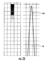
- a sub-pixel support tip 30 T can be created by using a low-intensity light spot, e.g., a low gray-value pixel, to make the cured area smaller, as shown in the gray-scale GS and resulting support tip 30 T of FIG. 33 .
- a low-intensity light spot e.g., a low gray-value pixel
- the actual supports 30 for the given surfaces may not be uniform, i.e., some supports can be made thicker than the others so that the thicker supports keep part 50 in place while the others serve to support the layer being built, as shown in FIG. 35 .
- Sub-pixel support tips 30 T may be used to reduce the bump size formed on part 50 , as shown in FIG. 33 .
- support reinforcement between supports 30 may be useful to add support reinforcement between supports 30 .
- the long section 30 L of support 30 is thicker, e.g., 2-pixel wide, and has reinforcement among them as shown in FIG. 30 .
- the reinforcements in the form of support posts 30 P between supports 30 at the long section 30 L greatly strengthen the support structures. For FTI technology, reinforcement only happens between the support posts 30 P within the same support grid to avoid long reinforcing lines.
- a typical reinforcement pattern that uses support posts 30 P is shown in the cross-sectional view of FIG. 36 .
- non-anchor support tips 30 T are grown into the last layer of part 50 for anchor-like reinforcement. Certain embodiments of the present invention do not include support tips 30 T that are grown into part 50 ; however, for the illustrated embodiments including support anchors AS, the anchors generally increase the strength of the supports. Hence, the number of the support tips 30 T interfacing with part 50 can be greatly reduced, especially, for parts with curved surfaces.
- An example is illustrated in the schematic side view of FIG. 37 .
- support tip 30 T is anchored to the part at an anchor AS that is one to four layers deep into the part.
- boundary support tips 30 T Due to the boundary support tips 30 T not being coincident with a predefined support pattern, the boundary support must be branched from the predefined pattern.
- One solution is to branch the boundary support tips 30 T from the support pattern at the last layer of reinforcement. This reduces the number of supports 30 and also reduces the possibility of blocking UV light during the build, as illustrated in FIG. 37 .
- the trapped resin between two neighboring supports 30 can be significantly reduced using this approach.
- a first advantage is that the support generation requires less human interaction because it can be automated, or performed in a manner that requires much less human interactions to edit supports as compared to present-day support-generation techniques. This tremendously increases the system throughput, and makes it possible to realize fast, quick, easy-to-use and office-friendly SFF systems.
- the support generation with anchor supports AS (constructed using sliced data) takes into account self-support distance, accumulating-support distance, and region identification.
- the support distribution has been optimized (effectively and efficiently supported) with consideration given to part manufacturability, without compromising the part quality.
- the support tips 30 T exactly interface with the part geometry.
- the sliced layer data, after compensation and geo-correction, is used to position the support anchors and generate the support structures. Thus, no offset exists between the built geometry and support locations.
- the support style converter can be used to convert support anchors into various support build styles, including support patterns having varying support thickness (see, e.g., FIG. 30 ), single-pixel or sub-pixel support tips, reinforcement structures, and branching structures.
- the resulting support tips 30 T always interface with the parts at the identical positions regardless of part locations.
Abstract
Description
| TABLE 1 |
| X, Y Pixel Tags for Steepness |
| X-Pixel | TAG | Y-Pixel | TAG | ||
| P1 | STEEP-X | P8 | STEEP-Y | ||
| P2 | STEEP-X | P9 | STEEP-Y | ||
| P3 | SHALLOW-X | P10 | STEEP-Y | ||
| /////// | ////////// | P11 | SHALLOW-Y | ||
| P4 | SHALLOW-X | P4 | SHALLOW-Y | ||
| P5 | SHALLOW-X | P12 | SHALLOW-Y | ||
| P6 | STEEP-X | P13 | STEEP-Y | ||
| P7 | STEEP-X | P14 | STEEP-Y | ||
| /////// | ////////// | P15 | STEEP-Y | ||
NS=NT−(NM+NC),
where NT is the total number of support pixels required, NM is the number of local maxima support pixels required, and NC is the number of centroid pixels required.
Claims (17)
NS=NT−(NM+NC),
Priority Applications (2)
| Application Number | Priority Date | Filing Date | Title |
|---|---|---|---|
| US12/212,242 US8046097B2 (en) | 2007-09-17 | 2008-09-17 | Region-based supports for parts produced by solid freeform fabrication |
| US13/238,007 US8285411B2 (en) | 2007-09-17 | 2011-09-21 | Region-based supports for parts produced by solid freeform fabrication |
Applications Claiming Priority (3)
| Application Number | Priority Date | Filing Date | Title |
|---|---|---|---|
| US97282307P | 2007-09-17 | 2007-09-17 | |
| US5507408P | 2008-05-21 | 2008-05-21 | |
| US12/212,242 US8046097B2 (en) | 2007-09-17 | 2008-09-17 | Region-based supports for parts produced by solid freeform fabrication |
Related Child Applications (1)
| Application Number | Title | Priority Date | Filing Date |
|---|---|---|---|
| US13/238,007 Continuation US8285411B2 (en) | 2007-09-17 | 2011-09-21 | Region-based supports for parts produced by solid freeform fabrication |
Publications (2)
| Publication Number | Publication Date |
|---|---|
| US20090072447A1 US20090072447A1 (en) | 2009-03-19 |
| US8046097B2 true US8046097B2 (en) | 2011-10-25 |
Family
ID=40383563
Family Applications (2)
| Application Number | Title | Priority Date | Filing Date |
|---|---|---|---|
| US12/212,242 Active 2029-09-19 US8046097B2 (en) | 2007-09-17 | 2008-09-17 | Region-based supports for parts produced by solid freeform fabrication |
| US13/238,007 Active US8285411B2 (en) | 2007-09-17 | 2011-09-21 | Region-based supports for parts produced by solid freeform fabrication |
Family Applications After (1)
| Application Number | Title | Priority Date | Filing Date |
|---|---|---|---|
| US13/238,007 Active US8285411B2 (en) | 2007-09-17 | 2011-09-21 | Region-based supports for parts produced by solid freeform fabrication |
Country Status (5)
| Country | Link |
|---|---|
| US (2) | US8046097B2 (en) |
| EP (2) | EP2481555B1 (en) |
| JP (1) | JP5777136B2 (en) |
| CN (1) | CN101855061B (en) |
| WO (1) | WO2009039159A2 (en) |
Cited By (11)
| Publication number | Priority date | Publication date | Assignee | Title |
|---|---|---|---|---|
| US20110178621A1 (en) * | 2010-01-15 | 2011-07-21 | Stratasys, Inc. | Method for generating and building support structures with deposition-based digital manufacturing systems |
| US20120205348A1 (en) * | 2011-02-14 | 2012-08-16 | United Technologies Corporation | Support structure for linear friction welding |
| US20140190942A1 (en) * | 2011-08-10 | 2014-07-10 | Bae Systems Plc | Forming a layered structure |
| US20140202999A1 (en) * | 2011-08-10 | 2014-07-24 | Andrew David Wescott | Forming a structure |
| US20140300017A1 (en) * | 2013-04-05 | 2014-10-09 | Formlabs | Additive fabrication support structures |
| US9522501B2 (en) | 2010-09-21 | 2016-12-20 | The Boeing Company | Continuous linear production in a selective laser sintering system |
| US9844917B2 (en) | 2014-06-13 | 2017-12-19 | Siemens Product Lifestyle Management Inc. | Support structures for additive manufacturing of solid models |
| US11072114B2 (en) | 2015-10-30 | 2021-07-27 | Seurat Technologies, Inc. | Variable print chamber walls for powder bed fusion additive manufacturing |
| US11117329B2 (en) | 2018-06-26 | 2021-09-14 | General Electric Company | Additively manufactured build assemblies having reduced distortion and residual stress |
| US11440097B2 (en) | 2019-02-12 | 2022-09-13 | General Electric Company | Methods for additively manufacturing components using lattice support structures |
| US11504771B2 (en) * | 2017-05-19 | 2022-11-22 | Premium Aerotec Gmbh | Method for producing an object by generative manufacturing, component, in particular for an aircraft or spacecraft, and computer-readable medium |
Families Citing this family (132)
| Publication number | Priority date | Publication date | Assignee | Title |
|---|---|---|---|---|
| US8556983B2 (en) | 2001-05-25 | 2013-10-15 | Conformis, Inc. | Patient-adapted and improved orthopedic implants, designs and related tools |
| US8735773B2 (en) | 2007-02-14 | 2014-05-27 | Conformis, Inc. | Implant device and method for manufacture |
| US8439926B2 (en) | 2001-05-25 | 2013-05-14 | Conformis, Inc. | Patient selectable joint arthroplasty devices and surgical tools |
| EP2591756A1 (en) | 2007-02-14 | 2013-05-15 | Conformis, Inc. | Implant device and method for manufacture |
| GB0719747D0 (en) * | 2007-10-10 | 2007-11-21 | Materialise Nv | Method and apparatus for automatic support generation for an object made by means of a rapid prototype production method |
| JP2011018205A (en) * | 2009-07-09 | 2011-01-27 | Amada Co Ltd | Nesting data generation device and nesting data generation method |
| US8318076B2 (en) * | 2010-06-15 | 2012-11-27 | 3D Systems, Inc. | Selective deposition modeling methods for improved support-object interface |
| US8707739B2 (en) | 2012-06-11 | 2014-04-29 | Johns Manville | Apparatus, systems and methods for conditioning molten glass |
| US9032760B2 (en) | 2012-07-03 | 2015-05-19 | Johns Manville | Process of using a submerged combustion melter to produce hollow glass fiber or solid glass fiber having entrained bubbles, and burners and systems to make such fibers |
| US10322960B2 (en) | 2010-06-17 | 2019-06-18 | Johns Manville | Controlling foam in apparatus downstream of a melter by adjustment of alkali oxide content in the melter |
| US8973405B2 (en) | 2010-06-17 | 2015-03-10 | Johns Manville | Apparatus, systems and methods for reducing foaming downstream of a submerged combustion melter producing molten glass |
| US8875544B2 (en) | 2011-10-07 | 2014-11-04 | Johns Manville | Burner apparatus, submerged combustion melters including the burner, and methods of use |
| US8997525B2 (en) | 2010-06-17 | 2015-04-07 | Johns Manville | Systems and methods for making foamed glass using submerged combustion |
| US8707740B2 (en) | 2011-10-07 | 2014-04-29 | Johns Manville | Submerged combustion glass manufacturing systems and methods |
| US9776903B2 (en) | 2010-06-17 | 2017-10-03 | Johns Manville | Apparatus, systems and methods for processing molten glass |
| US9096452B2 (en) | 2010-06-17 | 2015-08-04 | Johns Manville | Methods and systems for destabilizing foam in equipment downstream of a submerged combustion melter |
| US8769992B2 (en) | 2010-06-17 | 2014-07-08 | Johns Manville | Panel-cooled submerged combustion melter geometry and methods of making molten glass |
| US8650914B2 (en) | 2010-09-23 | 2014-02-18 | Johns Manville | Methods and apparatus for recycling glass products using submerged combustion |
| US8991215B2 (en) | 2010-06-17 | 2015-03-31 | Johns Manville | Methods and systems for controlling bubble size and bubble decay rate in foamed glass produced by a submerged combustion melter |
| US9021838B2 (en) | 2010-06-17 | 2015-05-05 | Johns Manville | Systems and methods for glass manufacturing |
| JP5737905B2 (en) * | 2010-11-01 | 2015-06-17 | 株式会社キーエンス | 3D modeling apparatus and 3D modeling method |
| WO2012131481A1 (en) * | 2011-03-29 | 2012-10-04 | Inspire Ag, Irpd | Part structure built by metal powder based added manufacturing |
| US20130053995A1 (en) * | 2011-08-25 | 2013-02-28 | Konica Minolta Business Technologies, Inc. | Three-dimensional object molding apparatus and control program |
| JP5408221B2 (en) * | 2011-10-14 | 2014-02-05 | コニカミノルタ株式会社 | Solid object shaping apparatus and control program |
| ITVI20110302A1 (en) * | 2011-11-23 | 2013-05-24 | Dws Srl | PERFECTED THREE-DIMENSIONAL OBJECT OBTAINED THROUGH A STEREOLITHOGRAPHIC PROCEDURE AND METHOD FOR THE DESIGN OF COMPUTERIZED GRAPHICS |
| DE102011119839B4 (en) | 2011-12-01 | 2019-11-28 | Kulzer Gmbh | Production of superstructures on a SLM system with subsequent milling of the connection geometry |
| US9408686B1 (en) | 2012-01-20 | 2016-08-09 | Conformis, Inc. | Devices, systems and methods for manufacturing orthopedic implants |
| CA2870017A1 (en) * | 2012-04-13 | 2013-10-17 | Conformis, Inc. | Devices and methods for additive manufacturing of implant components |
| US9533905B2 (en) | 2012-10-03 | 2017-01-03 | Johns Manville | Submerged combustion melters having an extended treatment zone and methods of producing molten glass |
| DE102012013318A1 (en) | 2012-07-06 | 2014-01-09 | Eos Gmbh Electro Optical Systems | Method and device for layering a three-dimensional object |
| FR2993801B1 (en) * | 2012-07-30 | 2014-08-22 | Phenix Systems | METHOD FOR MAKING A THREE-DIMENSIONAL OBJECT |
| US9327350B2 (en) * | 2012-08-16 | 2016-05-03 | Stratasys, Inc. | Additive manufacturing technique for printing three-dimensional parts with printed receiving surfaces |
| US9636229B2 (en) | 2012-09-20 | 2017-05-02 | Conformis, Inc. | Solid freeform fabrication of implant components |
| WO2014047514A1 (en) | 2012-09-21 | 2014-03-27 | Conformis, Inc. | Methods and systems for optimizing design and manufacture of implant components using solid freeform fabrication |
| EP2903941A4 (en) | 2012-10-03 | 2016-06-08 | Johns Manville | Methods and systems for destabilizing foam in equipment downstream of a submerged combustion melter |
| US9227865B2 (en) | 2012-11-29 | 2016-01-05 | Johns Manville | Methods and systems for making well-fined glass using submerged combustion |
| FR3002168B1 (en) * | 2013-02-15 | 2016-12-23 | Michelin & Cie | PIECE OBTAINED BY SELECTIVE FUSION OF A POWDER COMPRISING A MAIN ELEMENT AND RIGID SECONDARY ELEMENTS |
| US8870666B1 (en) | 2013-05-10 | 2014-10-28 | Renegade Manufacturing, LLC | Mud motor universal joint assembly |
| WO2014189499A1 (en) | 2013-05-22 | 2014-11-27 | Johns Manville | Submerged combustion burners and melters, and methods of use |
| WO2014189506A1 (en) | 2013-05-22 | 2014-11-27 | Johns Manville | Submerged combustion burners and melters, and methods of use |
| US10131563B2 (en) | 2013-05-22 | 2018-11-20 | Johns Manville | Submerged combustion burners |
| WO2014189501A1 (en) | 2013-05-22 | 2014-11-27 | Johns Manville | Submerged combustion burners, melters, and methods of use |
| WO2014189502A1 (en) | 2013-05-22 | 2014-11-27 | Johns Manville | Improved burner for submerged combustion melting |
| WO2014193388A1 (en) | 2013-05-30 | 2014-12-04 | Johns Manville | Submerged combustion glass melting systems and methods of use |
| SI3003997T1 (en) | 2013-05-30 | 2021-08-31 | Johns Manville | Submerged combustion burners with mixing improving means for glass melters, and use |
| EP2823952A1 (en) * | 2013-07-09 | 2015-01-14 | Siemens Aktiengesellschaft | Adaptation method and production method for components produced by means of SLM |
| DE102013011630B4 (en) * | 2013-07-12 | 2021-09-02 | Delcam, Ltd. | Method for calculating support structures |
| US10858278B2 (en) | 2013-07-18 | 2020-12-08 | Johns Manville | Combustion burner |
| US9688024B2 (en) * | 2013-08-30 | 2017-06-27 | Adobe Systems Incorporated | Adaptive supports for 3D printing |
| US9744725B2 (en) * | 2013-09-05 | 2017-08-29 | Adobe Systems Incorporated | Preserving thin components for 3D printing |
| DE102013218760A1 (en) * | 2013-09-19 | 2015-03-19 | Bayerische Motoren Werke Aktiengesellschaft | Method for producing a component in layers |
| US9279289B2 (en) | 2013-10-03 | 2016-03-08 | Renegade Manufacturing, LLC | Combination mud motor flow diverter and tiled bearing, and bearing assemblies including same |
| WO2015057886A1 (en) | 2013-10-15 | 2015-04-23 | Wolf And Associates, Inc. | Three-dimensional printer systems and methods |
| TWI548535B (en) * | 2013-11-18 | 2016-09-11 | 三緯國際立體列印科技股份有限公司 | Method of three-dimensional printing |
| US10226895B2 (en) * | 2013-12-03 | 2019-03-12 | Autodesk, Inc. | Generating support material for three-dimensional printing |
| WO2015092376A1 (en) * | 2013-12-17 | 2015-06-25 | Renishaw Plc | Improvements in or relating to the building of supports in additive manufacturing |
| US9789651B2 (en) * | 2014-01-09 | 2017-10-17 | Siemens Product Lifecycle Management Software, Inc. | Method for structure preserving topology optimization of lattice structures for additive manufacturing |
| USD733196S1 (en) | 2014-02-03 | 2015-06-30 | Wolf And Associates, Inc. | 3D printer enclosure |
| TWI629162B (en) * | 2014-03-25 | 2018-07-11 | Dws有限責任公司 | Computer-implementted method, and equipment and computer program product for defining a supporting structure for a three-dimensional object to be made through stereolithography |
| TWI576232B (en) * | 2014-03-25 | 2017-04-01 | Dws有限責任公司 | Improved computer-implemented method for defining the points of development of supporting elements of an object made by means of a stereolithography process |
| JP6416495B2 (en) * | 2014-04-28 | 2018-10-31 | ローランドディー.ジー.株式会社 | 3D modeling apparatus and 3D modeling method |
| FR3021902B1 (en) * | 2014-06-05 | 2016-07-22 | Inria Inst Nat Rech Informatique & Automatique | METHOD FOR DETERMINING THE POINTS TO BE SUPPORTED FOR AN OBJECT MADE BY MEANS OF AN ADDITIVE MANUFACTURING PROCESS; INFORMATION RECORDING MEDIUM AND RELATED SUPPORT STRUCTURE |
| WO2015196149A1 (en) | 2014-06-20 | 2015-12-23 | Velo3D, Inc. | Apparatuses, systems and methods for three-dimensional printing |
| US10730241B2 (en) * | 2014-11-17 | 2020-08-04 | Autodesk, Inc. | Techniques for automatically placing escape holes during three-dimensional printing |
| US10442138B2 (en) | 2014-12-01 | 2019-10-15 | Canon Kabushiki Kaisha | Three-dimensional object manufacturing method and three-dimensional shaping apparatus |
| USD760306S1 (en) | 2015-03-20 | 2016-06-28 | Wolf & Associates, Inc. | 3D printer enclosure |
| CN104772463B (en) * | 2015-04-14 | 2016-11-30 | 湖南华曙高科技有限责任公司 | A kind of supporting construction and manufacture method increasing material manufacture for metal |
| JP6579815B2 (en) * | 2015-06-17 | 2019-09-25 | ローランドディー.ジー.株式会社 | Support arrangement determination apparatus, three-dimensional modeling system, and support arrangement determination method |
| JP6538435B2 (en) * | 2015-06-17 | 2019-07-03 | ローランドディー.ジー.株式会社 | Support placement determination device, 3D modeling system, and support placement determination method |
| US10029419B2 (en) * | 2015-06-26 | 2018-07-24 | Xerox Corporation | Method for generating a framework for three dimensional printed parts |
| KR102413758B1 (en) * | 2015-07-13 | 2022-06-27 | 매시빗 3디 프린팅 테크놀로지스 리미티드 | support structure |
| US9751792B2 (en) | 2015-08-12 | 2017-09-05 | Johns Manville | Post-manufacturing processes for submerged combustion burner |
| US10670261B2 (en) | 2015-08-27 | 2020-06-02 | Johns Manville | Burner panels, submerged combustion melters, and methods |
| US10041666B2 (en) | 2015-08-27 | 2018-08-07 | Johns Manville | Burner panels including dry-tip burners, submerged combustion melters, and methods |
| US9815726B2 (en) | 2015-09-03 | 2017-11-14 | Johns Manville | Apparatus, systems, and methods for pre-heating feedstock to a melter using melter exhaust |
| US9982884B2 (en) | 2015-09-15 | 2018-05-29 | Johns Manville | Methods of melting feedstock using a submerged combustion melter |
| US10837705B2 (en) | 2015-09-16 | 2020-11-17 | Johns Manville | Change-out system for submerged combustion melting burner |
| US10081563B2 (en) | 2015-09-23 | 2018-09-25 | Johns Manville | Systems and methods for mechanically binding loose scrap |
| CN105160133B (en) * | 2015-09-30 | 2018-11-23 | 南京工程学院 | Progressive molding supporter method of formation based on STL triangular plate vertex iso-metric offset |
| US10144666B2 (en) | 2015-10-20 | 2018-12-04 | Johns Manville | Processing organics and inorganics in a submerged combustion melter |
| JP2018535121A (en) | 2015-11-06 | 2018-11-29 | ヴェロ・スリー・ディー・インコーポレイテッド | Proficient 3D printing |
| FR3043577B1 (en) | 2015-11-17 | 2022-06-17 | Snecma | METHOD FOR MANUFACTURING A BLADE PREFORM, A BLADE AND A DISTRIBUTOR SECTOR BY SELECTIVE POWDER BED FUSION |
| JP6480311B2 (en) | 2015-11-18 | 2019-03-06 | 富士フイルム株式会社 | Support member design apparatus, method, program, structure forming apparatus, and structure manufacturing method |
| US10183330B2 (en) | 2015-12-10 | 2019-01-22 | Vel03D, Inc. | Skillful three-dimensional printing |
| JP2017109427A (en) * | 2015-12-18 | 2017-06-22 | セイコーエプソン株式会社 | Three-dimensional object molding apparatus, three-dimensional object molding method, and control program for three-dimensional object molding apparatus |
| CN107053651B (en) * | 2016-02-05 | 2019-07-12 | 三纬国际立体列印科技股份有限公司 | Three dimensional model printing cuts layer method |
| US10434573B2 (en) | 2016-02-18 | 2019-10-08 | Velo3D, Inc. | Accurate three-dimensional printing |
| WO2017195342A1 (en) * | 2016-05-13 | 2017-11-16 | 三菱電機株式会社 | Processing device |
| US10061303B2 (en) * | 2016-05-18 | 2018-08-28 | Autodesk Inc. | Three-dimensional printing support models |
| US10994480B2 (en) | 2016-06-08 | 2021-05-04 | Wolf & Associates, Inc. | Three-dimensional printer systems and methods |
| US10246362B2 (en) | 2016-06-22 | 2019-04-02 | Johns Manville | Effective discharge of exhaust from submerged combustion melters and methods |
| US11691343B2 (en) | 2016-06-29 | 2023-07-04 | Velo3D, Inc. | Three-dimensional printing and three-dimensional printers |
| EP3263316B1 (en) | 2016-06-29 | 2019-02-13 | VELO3D, Inc. | Three-dimensional printing and three-dimensional printers |
| CN106079445B (en) * | 2016-06-30 | 2018-06-19 | 浙江大学 | A kind of 3 D-printing drives auxiliary support apparatus more |
| CN106079447B (en) * | 2016-06-30 | 2018-06-01 | 浙江大学 | A kind of 3 D-printing list drives auxiliary support apparatus |
| US10337732B2 (en) | 2016-08-25 | 2019-07-02 | Johns Manville | Consumable tip burners, submerged combustion melters including same, and methods |
| US10301208B2 (en) | 2016-08-25 | 2019-05-28 | Johns Manville | Continuous flow submerged combustion melter cooling wall panels, submerged combustion melters, and methods of using same |
| WO2018045120A1 (en) * | 2016-09-01 | 2018-03-08 | 3D Systems, Inc. | Improved additive manufacturing of a three-dimensional object |
| US10196294B2 (en) | 2016-09-07 | 2019-02-05 | Johns Manville | Submerged combustion melters, wall structures or panels of same, and methods of using same |
| JP2018047623A (en) * | 2016-09-21 | 2018-03-29 | ローランドディー.ジー.株式会社 | Molded article data generation device, molded article data generation program and molded article |
| US10259956B2 (en) | 2016-10-11 | 2019-04-16 | Xerox Corporation | Curable ink composition |
| US10233105B2 (en) | 2016-10-14 | 2019-03-19 | Johns Manville | Submerged combustion melters and methods of feeding particulate material into such melters |
| US20180126461A1 (en) | 2016-11-07 | 2018-05-10 | Velo3D, Inc. | Gas flow in three-dimensional printing |
| US10800108B2 (en) | 2016-12-02 | 2020-10-13 | Markforged, Inc. | Sinterable separation material in additive manufacturing |
| US10828698B2 (en) | 2016-12-06 | 2020-11-10 | Markforged, Inc. | Additive manufacturing with heat-flexed material feeding |
| US10000011B1 (en) | 2016-12-02 | 2018-06-19 | Markforged, Inc. | Supports for sintering additively manufactured parts |
| US20180186082A1 (en) | 2017-01-05 | 2018-07-05 | Velo3D, Inc. | Optics in three-dimensional printing |
| US11691339B2 (en) | 2017-02-15 | 2023-07-04 | Hewlett-Packard Development Company, L.P. | Product framing |
| JP2018134747A (en) * | 2017-02-20 | 2018-08-30 | 三菱重工業株式会社 | Three-dimensional posture determination device and control method and program for three-dimensional posture determination device |
| US20180250744A1 (en) | 2017-03-02 | 2018-09-06 | Velo3D, Inc. | Three-dimensional printing of three-dimensional objects |
| US20180281282A1 (en) | 2017-03-28 | 2018-10-04 | Velo3D, Inc. | Material manipulation in three-dimensional printing |
| CN107415217B (en) * | 2017-04-28 | 2019-07-23 | 西安理工大学 | A kind of design method of the indeterminate fixed end roof beam structure with self supporting structure |
| US10775770B2 (en) * | 2017-06-22 | 2020-09-15 | Autodesk, Inc. | Building and attaching support structures for 3D printing |
| EP3646115A1 (en) * | 2017-06-30 | 2020-05-06 | Nikon Corporation | Method for manufacturing an article made of a polymerized material |
| EP3643430A4 (en) * | 2017-07-26 | 2020-04-29 | Yamaha Hatsudoki Kabushiki Kaisha | Method for manufacturing metal member |
| CN110561756B (en) * | 2017-09-30 | 2020-11-17 | 浙江大学 | Three-dimensional printing stripping method |
| CN107856311A (en) * | 2017-11-13 | 2018-03-30 | 成都优材科技有限公司 | Tree-like supporting construction for 3D printing |
| NL2019907B1 (en) * | 2017-11-14 | 2019-05-20 | Atum Holding B V | Object support during 3d printing of an object based on a model |
| US10272525B1 (en) | 2017-12-27 | 2019-04-30 | Velo3D, Inc. | Three-dimensional printing systems and methods of their use |
| US10359764B1 (en) * | 2017-12-29 | 2019-07-23 | Palo Alto Research Center Incorporated | System and method for planning support removal in hybrid manufacturing with the aid of a digital computer |
| US10144176B1 (en) | 2018-01-15 | 2018-12-04 | Velo3D, Inc. | Three-dimensional printing systems and methods of their use |
| EP3810360A4 (en) * | 2018-05-22 | 2021-12-22 | Markforged, Inc. | Sinterable separation material in additive manufacturing |
| CN109049405B (en) * | 2018-07-24 | 2021-01-12 | 广西梧州国龙再生资源发展有限公司 | PET plastics 3D printer |
| KR102099014B1 (en) * | 2018-08-30 | 2020-04-08 | 전자부품연구원 | 2D Slicing Polyline based Support Structure Generation Method for 3D Printing |
| CN210651915U (en) * | 2018-09-21 | 2020-06-02 | 清锋(北京)科技有限公司 | 3D prints support piece and 3D and prints piece |
| CN109501249B (en) * | 2018-12-11 | 2024-02-23 | 西安国宏天易智能科技有限公司 | Variable-section open-pore grid supporting structure and generation method thereof |
| US11084224B2 (en) * | 2019-02-19 | 2021-08-10 | Arevo, Inc. | Three dimensional infill in additive manufacturing |
| US11155988B1 (en) | 2019-07-15 | 2021-10-26 | Summit Precast Concrete Lp | Systems and methods for stormwater detention |
| KR102338496B1 (en) * | 2020-11-25 | 2021-12-13 | 한국전자기술연구원 | Method for design modification based on layered cross-section outlines for 3D printing |
| CN113478819A (en) * | 2021-07-20 | 2021-10-08 | 深圳市鹏基光电有限公司 | Exposure display method and module for 3D printer, display device and storage medium |
| US11718964B2 (en) | 2021-09-13 | 2023-08-08 | Summit Precast Concrete, Lp | Bridge apparatus, systems and methods of construction |
| CN114670452A (en) * | 2022-03-31 | 2022-06-28 | 深圳市创想三维科技股份有限公司 | Support generation method and device, electronic equipment and storage medium |
Citations (16)
| Publication number | Priority date | Publication date | Assignee | Title |
|---|---|---|---|---|
| US4999143A (en) | 1988-04-18 | 1991-03-12 | 3D Systems, Inc. | Methods and apparatus for production of three-dimensional objects by stereolithography |
| US5454069A (en) | 1992-08-25 | 1995-09-26 | University Of Kentucky Research Foundation | Process for converting serial image to the sterolithography apparatus (SLA) slice file with automatic base and support generation |
| US5503785A (en) * | 1994-06-02 | 1996-04-02 | Stratasys, Inc. | Process of support removal for fused deposition modeling |
| US5587913A (en) * | 1993-01-15 | 1996-12-24 | Stratasys, Inc. | Method employing sequential two-dimensional geometry for producing shells for fabrication by a rapid prototyping system |
| US5595703A (en) | 1994-03-10 | 1997-01-21 | Materialise, Naamloze Vennootschap | Method for supporting an object made by means of stereolithography or another rapid prototype production method |
| US5943235A (en) | 1995-09-27 | 1999-08-24 | 3D Systems, Inc. | Rapid prototyping system and method with support region data processing |
| US6558606B1 (en) * | 2000-01-28 | 2003-05-06 | 3D Systems, Inc. | Stereolithographic process of making a three-dimensional object |
| US20040075196A1 (en) * | 1995-09-27 | 2004-04-22 | 3D Systems, Inc. | Selective deposition modeling method and apparatus for forming three-dimensional objects and supports |
| US6830643B1 (en) | 1999-11-16 | 2004-12-14 | 3D Systems Inc | Method of manufacturing an item and apparatus for manufacturing an item |
| US20040251581A1 (en) * | 2003-06-16 | 2004-12-16 | Jang Bor Z. | Micro- and nano-fabrication using focused plasma assisted vapor deposition |
| US20050131570A1 (en) * | 2000-09-07 | 2005-06-16 | Jamalabad Vikram R. | Procedures for rapid build and improved surface characteristics in layered manufacture |
| US20050138885A1 (en) * | 2000-12-13 | 2005-06-30 | Rotherroe Kevin C. | Unitary metal structural member with internal reinforcement |
| US7094320B1 (en) * | 1994-06-29 | 2006-08-22 | The Procter & Gamble Company | Multi-region paper structures having a transition region interconnecting relatively thinner regions disposed at different elevations, and apparatus and process for making the same |
| US20070233298A1 (en) * | 2006-04-03 | 2007-10-04 | Stratasys, Inc. | Method for optimizing spatial orientations of computer-aided design models |
| US20090001960A1 (en) * | 2007-06-29 | 2009-01-01 | Emulex Design & Manufacturing Corporation | Systems and methods for ASIC power consumption reduction |
| US20100042241A1 (en) * | 2006-10-10 | 2010-02-18 | Tomoyuki Inoue | Modeling data creating system, manufacturing method, and modeling data creating program |
Family Cites Families (16)
| Publication number | Priority date | Publication date | Assignee | Title |
|---|---|---|---|---|
| JPH05301293A (en) * | 1992-04-24 | 1993-11-16 | Fujitsu Ltd | Manufacture of support structural body in optical shaping method |
| CN1242293A (en) * | 1995-09-27 | 2000-01-26 | 3D系统公司 | Method and apparatus for data manipulation and system control in selective deposition modeling system |
| ATE223300T1 (en) * | 1995-09-27 | 2002-09-15 | 3D Systems Inc | SHAPING METHOD THROUGH SELECTIVE MATERIAL DEPOSIT AND DEVICE FOR SHAPING THREE-DIMENSIONAL OBJECTS WITH SUPPORT STRUCTURE |
| US6621914B1 (en) * | 1999-10-22 | 2003-09-16 | Lockheed Martin Corporation | Method and software-implemented apparatus for detecting objects in multi-dimensional data |
| US6708071B1 (en) * | 2000-08-15 | 2004-03-16 | Vought Aircraft Industries, Inc. | Method and system for defining and verifying a part |
| US6831638B2 (en) * | 2001-02-15 | 2004-12-14 | Lucent Technologies Inc. | Method and apparatus for generation of consistent parameterizations for a set of meshes |
| US7265565B2 (en) * | 2003-02-04 | 2007-09-04 | Microfabrica Inc. | Cantilever microprobes for contacting electronic components and methods for making such probes |
| JP4953408B2 (en) * | 2003-02-28 | 2012-06-13 | 日本テトラパック株式会社 | LAMINATED MATERIAL, LAMINATED MATERIAL MANUFACTURING METHOD, LAMINATED MATERIAL HEAT SEALING METHOD, AND PACKAGING CONTAINER |
| US7906061B2 (en) | 2005-05-03 | 2011-03-15 | 3D Systems, Inc. | Bubble-free cross-sections for use in solid imaging |
| US7467939B2 (en) | 2006-05-03 | 2008-12-23 | 3D Systems, Inc. | Material delivery tension and tracking system for use in solid imaging |
| US7814441B2 (en) * | 2006-05-09 | 2010-10-12 | Inus Technology, Inc. | System and method for identifying original design intents using 3D scan data |
| US8296813B2 (en) | 2006-06-22 | 2012-10-23 | Sony Computer Entertainment Inc. | Predictive frame dropping to enhance quality of service in streaming data |
| US7614866B2 (en) | 2007-01-17 | 2009-11-10 | 3D Systems, Inc. | Solid imaging apparatus and method |
| US7771183B2 (en) | 2007-01-17 | 2010-08-10 | 3D Systems, Inc. | Solid imaging system with removal of excess uncured build material |
| US8105066B2 (en) | 2007-01-17 | 2012-01-31 | 3D Systems, Inc. | Cartridge for solid imaging apparatus and method |
| EP2124778B1 (en) * | 2007-02-21 | 2019-09-25 | Benvenue Medical, Inc. | Devices for treating the spine |
-
2008
- 2008-09-17 JP JP2010525914A patent/JP5777136B2/en active Active
- 2008-09-17 EP EP12160994.5A patent/EP2481555B1/en active Active
- 2008-09-17 US US12/212,242 patent/US8046097B2/en active Active
- 2008-09-17 CN CN200880115528.6A patent/CN101855061B/en active Active
- 2008-09-17 WO PCT/US2008/076648 patent/WO2009039159A2/en active Application Filing
- 2008-09-17 EP EP08831614A patent/EP2203297B1/en active Active
-
2011
- 2011-09-21 US US13/238,007 patent/US8285411B2/en active Active
Patent Citations (18)
| Publication number | Priority date | Publication date | Assignee | Title |
|---|---|---|---|---|
| US4999143A (en) | 1988-04-18 | 1991-03-12 | 3D Systems, Inc. | Methods and apparatus for production of three-dimensional objects by stereolithography |
| US5454069A (en) | 1992-08-25 | 1995-09-26 | University Of Kentucky Research Foundation | Process for converting serial image to the sterolithography apparatus (SLA) slice file with automatic base and support generation |
| US5587913A (en) * | 1993-01-15 | 1996-12-24 | Stratasys, Inc. | Method employing sequential two-dimensional geometry for producing shells for fabrication by a rapid prototyping system |
| US5595703A (en) | 1994-03-10 | 1997-01-21 | Materialise, Naamloze Vennootschap | Method for supporting an object made by means of stereolithography or another rapid prototype production method |
| US5503785A (en) * | 1994-06-02 | 1996-04-02 | Stratasys, Inc. | Process of support removal for fused deposition modeling |
| US7094320B1 (en) * | 1994-06-29 | 2006-08-22 | The Procter & Gamble Company | Multi-region paper structures having a transition region interconnecting relatively thinner regions disposed at different elevations, and apparatus and process for making the same |
| US20040075196A1 (en) * | 1995-09-27 | 2004-04-22 | 3D Systems, Inc. | Selective deposition modeling method and apparatus for forming three-dimensional objects and supports |
| US6532394B1 (en) * | 1995-09-27 | 2003-03-11 | 3D Systems, Inc. | Method and apparatus for data manipulation and system control in a selective deposition modeling system |
| US5943235A (en) | 1995-09-27 | 1999-08-24 | 3D Systems, Inc. | Rapid prototyping system and method with support region data processing |
| US6830643B1 (en) | 1999-11-16 | 2004-12-14 | 3D Systems Inc | Method of manufacturing an item and apparatus for manufacturing an item |
| US6558606B1 (en) * | 2000-01-28 | 2003-05-06 | 3D Systems, Inc. | Stereolithographic process of making a three-dimensional object |
| US6797351B2 (en) * | 2000-01-28 | 2004-09-28 | 3D Systems, Inc. | Stereolithographic supports |
| US20050131570A1 (en) * | 2000-09-07 | 2005-06-16 | Jamalabad Vikram R. | Procedures for rapid build and improved surface characteristics in layered manufacture |
| US20050138885A1 (en) * | 2000-12-13 | 2005-06-30 | Rotherroe Kevin C. | Unitary metal structural member with internal reinforcement |
| US20040251581A1 (en) * | 2003-06-16 | 2004-12-16 | Jang Bor Z. | Micro- and nano-fabrication using focused plasma assisted vapor deposition |
| US20070233298A1 (en) * | 2006-04-03 | 2007-10-04 | Stratasys, Inc. | Method for optimizing spatial orientations of computer-aided design models |
| US20100042241A1 (en) * | 2006-10-10 | 2010-02-18 | Tomoyuki Inoue | Modeling data creating system, manufacturing method, and modeling data creating program |
| US20090001960A1 (en) * | 2007-06-29 | 2009-01-01 | Emulex Design & Manufacturing Corporation | Systems and methods for ASIC power consumption reduction |
Non-Patent Citations (3)
| Title |
|---|
| PCT International Search Report for Application No. PCT/US2008/076648, dated Feb. 23, 2010 (19 pages). |
| PCT International Search Report for Application No. PCT/US2008/076648, dated Nov. 11, 2009 (5 pages). |
| PCT Written Opinion of the International Searching Authority for International Application No. PCT/US2008/076648, dated Mar. 24, 2010 (11 pages). |
Cited By (22)
| Publication number | Priority date | Publication date | Assignee | Title |
|---|---|---|---|---|
| US9573323B2 (en) | 2010-01-15 | 2017-02-21 | Stratasys, Inc. | Method for generating and building support structures with deposition-based digital manufacturing systems |
| US8983643B2 (en) * | 2010-01-15 | 2015-03-17 | Stratasys, Inc. | Method for generating and building support structures with deposition-based digital manufacturing systems |
| US20110178621A1 (en) * | 2010-01-15 | 2011-07-21 | Stratasys, Inc. | Method for generating and building support structures with deposition-based digital manufacturing systems |
| US9522501B2 (en) | 2010-09-21 | 2016-12-20 | The Boeing Company | Continuous linear production in a selective laser sintering system |
| US9937557B2 (en) | 2010-09-21 | 2018-04-10 | The Boeing Company | Continuous linear production in a selective laser sintering system |
| US20120205348A1 (en) * | 2011-02-14 | 2012-08-16 | United Technologies Corporation | Support structure for linear friction welding |
| US8375581B2 (en) * | 2011-02-14 | 2013-02-19 | United Technologies Corporation | Support structure for linear friction welding |
| US20140202999A1 (en) * | 2011-08-10 | 2014-07-24 | Andrew David Wescott | Forming a structure |
| US20140190942A1 (en) * | 2011-08-10 | 2014-07-10 | Bae Systems Plc | Forming a layered structure |
| US20140300017A1 (en) * | 2013-04-05 | 2014-10-09 | Formlabs | Additive fabrication support structures |
| US9183325B2 (en) * | 2013-04-05 | 2015-11-10 | Formlabs, Inc. | Additive fabrication support structures |
| US11203162B2 (en) | 2013-04-05 | 2021-12-21 | Formlabs, Inc. | Additive fabrication support structures |
| US10011079B2 (en) | 2013-04-05 | 2018-07-03 | Formlabs, Inc. | Additive fabrication support structures |
| US10576689B2 (en) | 2013-04-05 | 2020-03-03 | Formlabs, Inc. | Additive fabrication support structures |
| US11801646B2 (en) | 2013-04-05 | 2023-10-31 | Formlabs, Inc. | Additive fabrication support structures |
| US9844917B2 (en) | 2014-06-13 | 2017-12-19 | Siemens Product Lifestyle Management Inc. | Support structures for additive manufacturing of solid models |
| US11691341B2 (en) | 2015-10-30 | 2023-07-04 | Seurat Technologies, Inc. | Part manipulation using printed manipulation points |
| US11072114B2 (en) | 2015-10-30 | 2021-07-27 | Seurat Technologies, Inc. | Variable print chamber walls for powder bed fusion additive manufacturing |
| US11504771B2 (en) * | 2017-05-19 | 2022-11-22 | Premium Aerotec Gmbh | Method for producing an object by generative manufacturing, component, in particular for an aircraft or spacecraft, and computer-readable medium |
| US20230085738A1 (en) * | 2017-05-19 | 2023-03-23 | Premium Aerotec Gmbh | Method for producing an object by generative manufacturing, component, in particular for an aircraft or spacecraft, and computer-readable medium |
| US11117329B2 (en) | 2018-06-26 | 2021-09-14 | General Electric Company | Additively manufactured build assemblies having reduced distortion and residual stress |
| US11440097B2 (en) | 2019-02-12 | 2022-09-13 | General Electric Company | Methods for additively manufacturing components using lattice support structures |
Also Published As
| Publication number | Publication date |
|---|---|
| US8285411B2 (en) | 2012-10-09 |
| JP5777136B2 (en) | 2015-09-09 |
| EP2481555A2 (en) | 2012-08-01 |
| US20120010741A1 (en) | 2012-01-12 |
| CN101855061B (en) | 2014-09-24 |
| US20090072447A1 (en) | 2009-03-19 |
| EP2481555A3 (en) | 2012-12-12 |
| CN101855061A (en) | 2010-10-06 |
| EP2203297A2 (en) | 2010-07-07 |
| WO2009039159A3 (en) | 2010-04-08 |
| WO2009039159A2 (en) | 2009-03-26 |
| JP2010538882A (en) | 2010-12-16 |
| EP2203297B1 (en) | 2012-05-16 |
| EP2481555B1 (en) | 2021-08-25 |
Similar Documents
| Publication | Publication Date | Title |
|---|---|---|
| US8046097B2 (en) | Region-based supports for parts produced by solid freeform fabrication | |
| EP3442775B1 (en) | Optimized three dimensional printing using ready-made supports | |
| US6261506B1 (en) | Method of making a three-dimensional object | |
| US6084980A (en) | Method of and apparatus for deriving data intermediate to cross-sectional data descriptive of a three-dimensional object | |
| EP1894704B1 (en) | Improved wall smoothness, feature accuracy and resolution in projected images via control of exposure levels in solid imaging | |
| Beaman et al. | Solid freeform fabrication: a new direction in manufacturing | |
| US8703037B2 (en) | Edge smoothness with low resolution projected images for use in solid imaging | |
| US6366825B1 (en) | Simultaneous multiple layer curing in stereolithography | |
| Onuh et al. | Optimising build parameters for improved surface finish in stereolithography | |
| EP0686480B1 (en) | Stereolithographic supports | |
| US5130064A (en) | Method of making a three dimensional object by stereolithography | |
| US4999143A (en) | Methods and apparatus for production of three-dimensional objects by stereolithography | |
| US20100228369A1 (en) | Method and apparatus for automatic support generation for an object made by means of a rapid prototype production method | |
| JP2001232690A (en) | Improved shaping method using stereolithography and improved support part for stereolithography | |
| JP2002086575A (en) | Method and apparatus for forming three-dimensional object | |
| JP2006099123A (en) | Enhanced building techniques in stereolithography | |
| EP1025980B1 (en) | Stereolithographic method and apparatus for production of three dimensional objects using recoating parameters for groups of layers | |
| EP3334588A1 (en) | 3d printing using preformed reuseable support structure | |
| US20100168890A1 (en) | Three-Dimensional Data Extraction Using Ray Casting | |
| Chen | Intelligent scanning in selective laser sintering | |
| Kim | Optimal model-building strategy for rapid prototype manufacturing of sculpture surface |
Legal Events
| Date | Code | Title | Description |
|---|---|---|---|
| AS | Assignment |
Owner name: 3D SYSTEMS, INC., SOUTH CAROLINA Free format text: ASSIGNMENT OF ASSIGNORS INTEREST;ASSIGNORS:HULL, CHARLES;MOJDEH, MEHDI;KULKARNI, RAJEEV;AND OTHERS;REEL/FRAME:021777/0878;SIGNING DATES FROM 20080917 TO 20081007 Owner name: 3D SYSTEMS, INC., SOUTH CAROLINA Free format text: ASSIGNMENT OF ASSIGNORS INTEREST;ASSIGNORS:HULL, CHARLES;MOJDEH, MEHDI;KULKARNI, RAJEEV;AND OTHERS;SIGNING DATES FROM 20080917 TO 20081007;REEL/FRAME:021777/0878 |
|
| STCF | Information on status: patent grant |
Free format text: PATENTED CASE |
|
| FPAY | Fee payment |
Year of fee payment: 4 |
|
| AS | Assignment |
Owner name: HSBC BANK USA, NATIONAL ASSOCIATION, AS ADMINISTRA Free format text: SECURITY INTEREST;ASSIGNOR:3D SYSTEMS, INC.;REEL/FRAME:048456/0017 Effective date: 20190227 Owner name: HSBC BANK USA, NATIONAL ASSOCIATION, AS ADMINISTRATIVE AGENT, NEW YORK Free format text: SECURITY INTEREST;ASSIGNOR:3D SYSTEMS, INC.;REEL/FRAME:048456/0017 Effective date: 20190227 |
|
| MAFP | Maintenance fee payment |
Free format text: PAYMENT OF MAINTENANCE FEE, 8TH YEAR, LARGE ENTITY (ORIGINAL EVENT CODE: M1552); ENTITY STATUS OF PATENT OWNER: LARGE ENTITY Year of fee payment: 8 |
|
| AS | Assignment |
Owner name: 3D SYSTEMS, INC., SOUTH CAROLINA Free format text: RELEASE BY SECURED PARTY;ASSIGNOR:HSBC BANK USA, NATIONAL ASSOCIATION;REEL/FRAME:057651/0374 Effective date: 20210824 |
|
| MAFP | Maintenance fee payment |
Free format text: PAYMENT OF MAINTENANCE FEE, 12TH YEAR, LARGE ENTITY (ORIGINAL EVENT CODE: M1553); ENTITY STATUS OF PATENT OWNER: LARGE ENTITY Year of fee payment: 12 |