US8058933B2 - Low frequency clock generation - Google Patents
Low frequency clock generation Download PDFInfo
- Publication number
- US8058933B2 US8058933B2 US11/232,581 US23258105A US8058933B2 US 8058933 B2 US8058933 B2 US 8058933B2 US 23258105 A US23258105 A US 23258105A US 8058933 B2 US8058933 B2 US 8058933B2
- Authority
- US
- United States
- Prior art keywords
- oscillator
- setting
- frequency
- oscillators
- resonator
- Prior art date
- Legal status (The legal status is an assumption and is not a legal conclusion. Google has not performed a legal analysis and makes no representation as to the accuracy of the status listed.)
- Expired - Fee Related, expires
Links
- 239000000758 substrate Substances 0.000 claims description 21
- 239000013078 crystal Substances 0.000 description 8
- 239000004065 semiconductor Substances 0.000 description 4
- 238000000034 method Methods 0.000 description 3
- 230000010355 oscillation Effects 0.000 description 3
- 238000004519 manufacturing process Methods 0.000 description 2
- 238000012544 monitoring process Methods 0.000 description 2
- 230000000694 effects Effects 0.000 description 1
- 230000010354 integration Effects 0.000 description 1
- 238000004806 packaging method and process Methods 0.000 description 1
- 238000012858 packaging process Methods 0.000 description 1
- 239000010453 quartz Substances 0.000 description 1
- 229910052710 silicon Inorganic materials 0.000 description 1
- 239000010703 silicon Substances 0.000 description 1
- VYPSYNLAJGMNEJ-UHFFFAOYSA-N silicon dioxide Inorganic materials O=[Si]=O VYPSYNLAJGMNEJ-UHFFFAOYSA-N 0.000 description 1
Images


Classifications
-
- H—ELECTRICITY
- H03—ELECTRONIC CIRCUITRY
- H03L—AUTOMATIC CONTROL, STARTING, SYNCHRONISATION, OR STABILISATION OF GENERATORS OF ELECTRONIC OSCILLATIONS OR PULSES
- H03L1/00—Stabilisation of generator output against variations of physical values, e.g. power supply
- H03L1/02—Stabilisation of generator output against variations of physical values, e.g. power supply against variations of temperature only
- H03L1/028—Stabilisation of generator output against variations of physical values, e.g. power supply against variations of temperature only of generators comprising piezoelectric resonators
-
- H—ELECTRICITY
- H03—ELECTRONIC CIRCUITRY
- H03B—GENERATION OF OSCILLATIONS, DIRECTLY OR BY FREQUENCY-CHANGING, BY CIRCUITS EMPLOYING ACTIVE ELEMENTS WHICH OPERATE IN A NON-SWITCHING MANNER; GENERATION OF NOISE BY SUCH CIRCUITS
- H03B21/00—Generation of oscillations by combining unmodulated signals of different frequencies
- H03B21/01—Generation of oscillations by combining unmodulated signals of different frequencies by beating unmodulated signals of different frequencies
-
- H—ELECTRICITY
- H03—ELECTRONIC CIRCUITRY
- H03L—AUTOMATIC CONTROL, STARTING, SYNCHRONISATION, OR STABILISATION OF GENERATORS OF ELECTRONIC OSCILLATIONS OR PULSES
- H03L1/00—Stabilisation of generator output against variations of physical values, e.g. power supply
- H03L1/02—Stabilisation of generator output against variations of physical values, e.g. power supply against variations of temperature only
- H03L1/022—Stabilisation of generator output against variations of physical values, e.g. power supply against variations of temperature only by indirect stabilisation, i.e. by generating an electrical correction signal which is a function of the temperature
- H03L1/027—Stabilisation of generator output against variations of physical values, e.g. power supply against variations of temperature only by indirect stabilisation, i.e. by generating an electrical correction signal which is a function of the temperature by using frequency conversion means which is variable with temperature, e.g. mixer, frequency divider, pulse add/substract logic circuit
Definitions
- Crystal oscillators can be temperature compensated.
- the fundamental resonant frequency of the crystal typically ranges from below 10 MHz up to perhaps 70 MHz. This tone is then used in a phase lock loop to control a higher frequency voltage controlled oscillator that generates the desired frequency of operation of the system.
- the temperature controlled crystal oscillator typically costs between $0.30 and $1.00 depending upon performance requirements and is considered a commodity in many markets with manufacturers competing primarily on price.
- the invention provides an energy efficient, small, and inexpensive clock for use in integrated circuit designs.
- a first and a second resonator are fabricated monolithically adjacent to one another.
- the first resonator is the reference resonator.
- the resonant frequency of the second resonator is offset by a difference frequency Fo from the first resonator.
- Each resonator is included within an oscillator.
- a mixer receives the output of both oscillators.
- a low pass filter receives the mixer output and generates a clock signal whose frequency is equal to the difference frequency Fo.
- FIG. 1 is an embodiment of the present invention.
- FIG. 2 is an embodiment of the present invention.
- FIG. 3 is an embodiment of the present invention.
- FIG. 4 is an alternative embodiment of the present invention.
- FIG. 1 is an embodiment 10 of the present invention.
- a first and a second resonator 12 A, 14 A are fabricated monolithically adjacent to one another.
- the first resonator 12 A is the reference resonator.
- the resonant frequency of the second resonator 14 A is offset by a difference frequency Fo from the first resonator 12 A.
- Each resonator 12 A, 14 A is included within an oscillator 12 , 14 , respectively.
- a mixer 16 receives the output of both oscillators 12 , 14 .
- a low pass filter 18 receives the mixer output and generates a clock signal whose frequency is equal to the difference frequency, Fo.
- this offset frequency can range from DC to many GHz.
- a practical frequency offset includes the typical range of crystal oscillators and may be considerably extended in range at high frequencies. Thus, this scheme could easily generate a frequency between 10 and 500 MHz.
- the oscillation frequencies are determined by the resonant frequency of the respective resonator.
- the mixer output signal includes a high frequency component in the range of the resonant frequencies and low frequency component having a frequency proportional to the difference frequency Fo of the two oscillators.
- the low frequency component may be extracted using a low pass filter to generate the desired lower frequency clock signal.
- the resonators may be Film Bulk Acoustic Resonators (FBARs).
- FBAR Film Bulk Acoustic Resonators
- the FBAR can be built on a semiconductor substrate, such as silicon.
- the rest of the oscillator circuit, excluding the FBAR is built on a semiconductor substrate using CMOS, Bipolar, or BiCMOS processes. This allows for a variety of manufacturing packaging and integration strategies to create a clock generation circuit.
- the resonator may be directly attached to the rest of the oscillator during the packaging process by flip-chip interconnect of the FBAR device or die stacking and wire bonding the devices together, for example.
- the FBAR device may be integrated directly with the oscillator circuit on the same substrate.
- the FBAR device may be adjacent to the oscillator circuit together on a separate substrate, with electrical connections provided by flip-chip interconnect or wire bonding and electrically connected to the substrate through wire bonding.
- the resonators can be fabricated to have tracking different coefficients of temperature drift. In a preferred embodiment, the temperature coefficients are designed so that the difference frequency is constant with temperature.
- the oscillatorclock generation circuit may be attached to a substrate as a separate die, e.g. to using as an illustrative example flip-chipping or die stacking technology.
- a die that includes the oscillatorclock generation circuit is attached by either flipping the oscillator component onto a transceiver integrated circuit (IC) and also connecting the I/O pads or attaching it face up and using bond wires to make the connections.
- the oscillatorclock generation circuit may be fabricated on the same substrate as an integrated circuit.
- FIG. 2 illustrates an alternate embodiment, programmability of the output frequency is included while improving the accuracy and temperature characteristics of the oscillator.
- a temperature monitoring circuit 20 and a temperature control circuit 22 provide inputs to a VCO control circuit 24 .
- a first register 26 stores a selected oscillator frequency offset setting.
- a second register 28 stores a temperature compensation setting.
- the VCO control circuit 24 receives the values from the first and the second registers 26 , 28 .
- the second oscillator 14 is a voltage controlled oscillator (VCO) or digitally controlled oscillator that allows the frequency of the oscillation to be modified by changing a control voltage or digital control value.
- VCO voltage controlled oscillator
- a corresponding change in the output clock frequency occurs with a change in the frequency of the second oscillator 14 since the output clock frequency is equal to the difference between the difference of the two oscillators.
- a specific output clock frequency in manufacturing When a specific output clock frequency in manufacturing is desired, it may be set by measuring the output clock frequency for various control values, e.g. voltage or digital. In the next step, the desired output frequency is programmed and may be stored in a register.
- a temperature monitoring and control circuits 20 , 22 the effects of temperature may be cancelled out.
- Sensing temperature using diodes or other semiconductor devices built into the substrate is well known.
- the sensed temperature of the substrate provides a control values to the temperature control circuit. Typically, this responds in a linear manner to a linear change in control value but may be non-linear depending upon the requirements of the system if the temperature monitor is non-linear or the VCO control is non-linear.
- a second register may be programmed and adjusted until the output frequency matches the desired frequency.
- This second register provides temperature compensation of the output clock frequency.
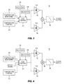
- FIG. 3 illustrates an alternate embodiment.
- the first and second oscillators 12 , 14 may both be VCOs receiving the output of the VCO control circuit 24 .
- This provides symmetric design of the oscillators used to generate the difference frequency for the output clock frequency.
- the frequency changes due to process variations will track.
- To maintain the matching of the biasing of the VCOS VCOs requires symmetric application of the control for to both of them.
- the first oscillator 12 can adjust between frequency F 1 A and F 1 B, where F 1 A ⁇ F 1 B
- the second oscillator 14 can adjust between frequency F 2 A and F 2 B, where F 2 A ⁇ F 2 B and F 1 A ⁇ F 1 B ⁇ F 2 A ⁇ F 2 B
- the first oscillator 12 would operate at frequency F 1 A and the second oscillator 14 would operate at frequency F 2 B yielding the maximum value for the difference frequency F 2 B-F 1 A at the output.
- the first oscillator 12 would operate at frequency F 1 B and the second oscillator 14 would operate at frequency F 2 A yielding the minimum value of the difference frequency F 2 A-F 1 B at the output.
- Symmetric design would match the amount of change in the first oscillator 12 with that of the second oscillator 14 in a continuous manner.
- FIG. 4 is an alternate embodiment.
- An input signal is added to the VCO control circuit 24 .
- the input signal may be a modulation source whereby the data represented at the signal Vin will modulate the carrier frequency, e.g. a simple form of Frequency Shift Keying (FSK).
- FSK Frequency Shift Keying
- the output clock is now the carrier frequency with a modulated FSK signal on top of the carrier.
Abstract
Description
Claims (17)
Priority Applications (5)
| Application Number | Priority Date | Filing Date | Title |
|---|---|---|---|
| US11/232,581 US8058933B2 (en) | 2005-09-21 | 2005-09-21 | Low frequency clock generation |
| TW95115726A TWI402658B (en) | 2005-05-13 | 2006-05-03 | Low frequency clock generation |
| GB0609026A GB2426133A (en) | 2005-05-13 | 2006-05-05 | Clock generation circuit mixing two oscillator signals |
| JP2006133258A JP4926539B2 (en) | 2005-05-13 | 2006-05-12 | Low frequency clock generation |
| CN200610144433XA CN1972127B (en) | 2005-05-13 | 2006-05-15 | Generation circuit and device of low-frequency clock |
Applications Claiming Priority (1)
| Application Number | Priority Date | Filing Date | Title |
|---|---|---|---|
| US11/232,581 US8058933B2 (en) | 2005-09-21 | 2005-09-21 | Low frequency clock generation |
Publications (2)
| Publication Number | Publication Date |
|---|---|
| US20070063775A1 US20070063775A1 (en) | 2007-03-22 |
| US8058933B2 true US8058933B2 (en) | 2011-11-15 |
Family
ID=37883467
Family Applications (1)
| Application Number | Title | Priority Date | Filing Date |
|---|---|---|---|
| US11/232,581 Expired - Fee Related US8058933B2 (en) | 2005-05-13 | 2005-09-21 | Low frequency clock generation |
Country Status (1)
| Country | Link |
|---|---|
| US (1) | US8058933B2 (en) |
Cited By (4)
| Publication number | Priority date | Publication date | Assignee | Title |
|---|---|---|---|---|
| US20100281290A1 (en) * | 2009-04-30 | 2010-11-04 | Hong Fu Jin Precision Industry (Shenzhen) Co., Ltd | Clock generating circuit of computer |
| US20140213202A1 (en) * | 2013-01-29 | 2014-07-31 | Medtronic, Inc. | Medical device communication system and method |
| US9654120B2 (en) | 2012-07-26 | 2017-05-16 | Qualcomm Incorporated | System and method of determining an oscillator gain |
| US10247621B1 (en) * | 2015-09-13 | 2019-04-02 | Sitime Corporation | High resolution temperature sensor |
Families Citing this family (1)
| Publication number | Priority date | Publication date | Assignee | Title |
|---|---|---|---|---|
| US8090067B2 (en) * | 2008-05-23 | 2012-01-03 | Avago Technologies Fiber Ip (Singapore) Pte. Ltd. | Circuits and methods for clock and data recovery |
Citations (12)
| Publication number | Priority date | Publication date | Assignee | Title |
|---|---|---|---|---|
| US3249888A (en) | 1963-05-04 | 1966-05-03 | Wandel & Goltermann | Beat frequency signal generator |
| US3421106A (en) | 1967-10-03 | 1969-01-07 | Hewlett Packard Co | Differential frequency transducer |
| US4916411A (en) * | 1988-06-08 | 1990-04-10 | Hewlett-Packard Company | Variable frequency jitter generator |
| JPH06276020A (en) | 1993-01-25 | 1994-09-30 | Matsushita Electric Ind Co Ltd | Temperature compensated crystal oscillator |
| JPH0870232A (en) | 1994-08-29 | 1996-03-12 | Meidensha Corp | Surface acoustic wave element and oscillat0r |
| JPH0870218A (en) | 1994-08-29 | 1996-03-12 | Murata Mfg Co Ltd | Temperature compensated crystal oscillator |
| US6404293B1 (en) * | 1999-10-21 | 2002-06-11 | Broadcom Corporation | Adaptive radio transceiver with a local oscillator |
| US6407456B1 (en) * | 1996-02-20 | 2002-06-18 | Micron Technology, Inc. | Multi-chip device utilizing a flip chip and wire bond assembly |
| US6459341B1 (en) | 1999-10-27 | 2002-10-01 | Nec Corporation | Voltage controlled oscillation device |
| US20030052743A1 (en) | 2000-01-10 | 2003-03-20 | Piazza Silvio Dalla | Device for producing a signal having a substantially temperature-independent frequency |
| US7109637B2 (en) * | 2003-07-09 | 2006-09-19 | Tdk Corporation | Thin-film bulk acoustic oscillator and method of manufacturing same |
| US7212075B2 (en) * | 2003-07-18 | 2007-05-01 | Halliburton Energy Services, Inc. | Downhole clock having temperature compensation |
Family Cites Families (1)
| Publication number | Priority date | Publication date | Assignee | Title |
|---|---|---|---|---|
| JPS5933388B2 (en) * | 1976-03-19 | 1984-08-15 | 高美 上原 | Single-operable biopsy fiberscope |
-
2005
- 2005-09-21 US US11/232,581 patent/US8058933B2/en not_active Expired - Fee Related
Patent Citations (12)
| Publication number | Priority date | Publication date | Assignee | Title |
|---|---|---|---|---|
| US3249888A (en) | 1963-05-04 | 1966-05-03 | Wandel & Goltermann | Beat frequency signal generator |
| US3421106A (en) | 1967-10-03 | 1969-01-07 | Hewlett Packard Co | Differential frequency transducer |
| US4916411A (en) * | 1988-06-08 | 1990-04-10 | Hewlett-Packard Company | Variable frequency jitter generator |
| JPH06276020A (en) | 1993-01-25 | 1994-09-30 | Matsushita Electric Ind Co Ltd | Temperature compensated crystal oscillator |
| JPH0870232A (en) | 1994-08-29 | 1996-03-12 | Meidensha Corp | Surface acoustic wave element and oscillat0r |
| JPH0870218A (en) | 1994-08-29 | 1996-03-12 | Murata Mfg Co Ltd | Temperature compensated crystal oscillator |
| US6407456B1 (en) * | 1996-02-20 | 2002-06-18 | Micron Technology, Inc. | Multi-chip device utilizing a flip chip and wire bond assembly |
| US6404293B1 (en) * | 1999-10-21 | 2002-06-11 | Broadcom Corporation | Adaptive radio transceiver with a local oscillator |
| US6459341B1 (en) | 1999-10-27 | 2002-10-01 | Nec Corporation | Voltage controlled oscillation device |
| US20030052743A1 (en) | 2000-01-10 | 2003-03-20 | Piazza Silvio Dalla | Device for producing a signal having a substantially temperature-independent frequency |
| US7109637B2 (en) * | 2003-07-09 | 2006-09-19 | Tdk Corporation | Thin-film bulk acoustic oscillator and method of manufacturing same |
| US7212075B2 (en) * | 2003-07-18 | 2007-05-01 | Halliburton Energy Services, Inc. | Downhole clock having temperature compensation |
Non-Patent Citations (1)
| Title |
|---|
| Patent Application in Great Britian No. 06090260.0 Search Report dated Jul. 21, 2006. |
Cited By (6)
| Publication number | Priority date | Publication date | Assignee | Title |
|---|---|---|---|---|
| US20100281290A1 (en) * | 2009-04-30 | 2010-11-04 | Hong Fu Jin Precision Industry (Shenzhen) Co., Ltd | Clock generating circuit of computer |
| US9654120B2 (en) | 2012-07-26 | 2017-05-16 | Qualcomm Incorporated | System and method of determining an oscillator gain |
| US20140213202A1 (en) * | 2013-01-29 | 2014-07-31 | Medtronic, Inc. | Medical device communication system and method |
| US8954008B2 (en) * | 2013-01-29 | 2015-02-10 | Medtronic, Inc. | Medical device communication system and method |
| US10247621B1 (en) * | 2015-09-13 | 2019-04-02 | Sitime Corporation | High resolution temperature sensor |
| US10622973B1 (en) * | 2015-09-13 | 2020-04-14 | Sitime Corporation | Temperature sensor based on ratio of clock signals from respective MEMS resonators |
Also Published As
| Publication number | Publication date |
|---|---|
| US20070063775A1 (en) | 2007-03-22 |
Similar Documents
| Publication | Publication Date | Title |
|---|---|---|
| US7990229B2 (en) | Methods and devices for compensating a signal using resonators | |
| WO1998031104A1 (en) | Pll oscillator and method for manufacturing the same | |
| US7215214B1 (en) | Resonator and amplifying oscillator circuit having a high resolution skew-compensated frequency synthesizer integrated on a single substrate | |
| Ruffieux et al. | Silicon Resonator Based 3.2$\mu $ W Real Time Clock With $\pm $10 ppm Frequency Accuracy | |
| US10608586B2 (en) | Resonator device, electronic apparatus, and vehicle | |
| US20050122179A1 (en) | Voltage-controlled oscillator, clock converter, and electronic device | |
| CN108476022B (en) | Hybrid RC/Crystal Oscillator | |
| US8058933B2 (en) | Low frequency clock generation | |
| WO2006000611A1 (en) | Frequency synthesizer | |
| WO2007068283A1 (en) | Sensor interface | |
| US20120013413A1 (en) | Timing oscillators and related methods | |
| CN113031428B (en) | Real-time clock device and electronic apparatus | |
| US7583154B1 (en) | Voltage controlled oscillator | |
| US20140139293A1 (en) | Integrated reference frequency generator | |
| JP4926539B2 (en) | Low frequency clock generation | |
| US11201588B2 (en) | Oscillator and electronic apparatus | |
| McCorquodale et al. | A history of the development of CMOS oscillators: The dark horse in frequency control | |
| JPH088740A (en) | Pll oscillator and piezo-oscillator | |
| US20190006989A1 (en) | Resonator Device, Electronic Apparatus, And Vehicle | |
| Kuypers et al. | Wafer-level chip scale MEMS oscillator for wireless applications | |
| US10594295B2 (en) | Resonator device, electronic apparatus, and vehicle | |
| Kuypers | High frequency oscillators for mobile devices | |
| US20240048100A1 (en) | Circuit Apparatus And Oscillator | |
| JP2001186020A (en) | Oscillator and its frequency setting method | |
| JP7415535B2 (en) | Oscillators and electronic equipment |
Legal Events
| Date | Code | Title | Description |
|---|---|---|---|
| AS | Assignment |
Owner name: AGILENT TECHNOLOGIES, INC., COLORADO Free format text: ASSIGNMENT OF ASSIGNORS INTEREST;ASSIGNORS:FRANK, MICHAEL LOUIS;UNKRICH, MARK A;REEL/FRAME:017141/0476 Effective date: 20050921 |
|
| AS | Assignment |
Owner name: AVAGO TECHNOLOGIES GENERAL IP PTE. LTD., SINGAPORE Free format text: ASSIGNMENT OF ASSIGNORS INTEREST;ASSIGNOR:AGILENT TECHNOLOGIES, INC.;REEL/FRAME:017206/0666 Effective date: 20051201 Owner name: AVAGO TECHNOLOGIES GENERAL IP PTE. LTD.,SINGAPORE Free format text: ASSIGNMENT OF ASSIGNORS INTEREST;ASSIGNOR:AGILENT TECHNOLOGIES, INC.;REEL/FRAME:017206/0666 Effective date: 20051201 |
|
| AS | Assignment |
Owner name: AVAGO TECHNOLOGIES WIRELESS IP (SINGAPORE) PTE. LT Free format text: ASSIGNMENT OF ASSIGNORS INTEREST;ASSIGNOR:AVAGO TECHNOLOGIES GENERAL IP (SINGAPORE) PTE. LTD.;REEL/FRAME:017675/0477 Effective date: 20051201 |
|
| REMI | Maintenance fee reminder mailed | ||
| LAPS | Lapse for failure to pay maintenance fees | ||
| STCH | Information on status: patent discontinuation |
Free format text: PATENT EXPIRED DUE TO NONPAYMENT OF MAINTENANCE FEES UNDER 37 CFR 1.362 |
|
| FP | Lapsed due to failure to pay maintenance fee |
Effective date: 20151115 |
|
| AS | Assignment |
Owner name: AVAGO TECHNOLOGIES GENERAL IP (SINGAPORE) PTE. LTD Free format text: CORRECTIVE ASSIGNMENT TO CORRECT THE ASSIGNEE NAME PREVIOUSLY RECORDED AT REEL: 017206 FRAME: 0666. ASSIGNOR(S) HEREBY CONFIRMS THE ASSIGNMENT;ASSIGNOR:AGILENT TECHNOLOGIES, INC.;REEL/FRAME:038632/0662 Effective date: 20051201 |