US8059229B2 - Light control element, surface light source device and liquid crystal display device - Google Patents
Light control element, surface light source device and liquid crystal display device Download PDFInfo
- Publication number
- US8059229B2 US8059229B2 US12/293,521 US29352108A US8059229B2 US 8059229 B2 US8059229 B2 US 8059229B2 US 29352108 A US29352108 A US 29352108A US 8059229 B2 US8059229 B2 US 8059229B2
- Authority
- US
- United States
- Prior art keywords
- prism
- output
- light
- plane
- prism surface
- Prior art date
- Legal status (The legal status is an assumption and is not a legal conclusion. Google has not performed a legal analysis and makes no representation as to the accuracy of the status listed.)
- Expired - Fee Related, expires
Links
- 239000004973 liquid crystal related substance Substances 0.000 title claims description 31
- 239000000463 material Substances 0.000 claims description 7
- 238000009826 distribution Methods 0.000 description 13
- 238000000034 method Methods 0.000 description 8
- 230000005484 gravity Effects 0.000 description 6
- 238000004088 simulation Methods 0.000 description 5
- 238000009833 condensation Methods 0.000 description 4
- 230000005494 condensation Effects 0.000 description 4
- 230000004048 modification Effects 0.000 description 4
- 238000012986 modification Methods 0.000 description 4
- 239000011347 resin Substances 0.000 description 4
- 229920005989 resin Polymers 0.000 description 4
- 229920000178 Acrylic resin Polymers 0.000 description 2
- 239000004925 Acrylic resin Substances 0.000 description 2
- PPBRXRYQALVLMV-UHFFFAOYSA-N Styrene Chemical compound C=CC1=CC=CC=C1 PPBRXRYQALVLMV-UHFFFAOYSA-N 0.000 description 2
- 230000006872 improvement Effects 0.000 description 2
- 238000004519 manufacturing process Methods 0.000 description 2
- 230000003287 optical effect Effects 0.000 description 2
- 239000004952 Polyamide Substances 0.000 description 1
- 229910052782 aluminium Inorganic materials 0.000 description 1
- XAGFODPZIPBFFR-UHFFFAOYSA-N aluminium Chemical compound [Al] XAGFODPZIPBFFR-UHFFFAOYSA-N 0.000 description 1
- 238000005452 bending Methods 0.000 description 1
- 230000005540 biological transmission Effects 0.000 description 1
- 230000015572 biosynthetic process Effects 0.000 description 1
- 239000012461 cellulose resin Substances 0.000 description 1
- 239000002131 composite material Substances 0.000 description 1
- 230000003247 decreasing effect Effects 0.000 description 1
- 230000000593 degrading effect Effects 0.000 description 1
- 230000003467 diminishing effect Effects 0.000 description 1
- 230000000694 effects Effects 0.000 description 1
- 238000001125 extrusion Methods 0.000 description 1
- 239000011888 foil Substances 0.000 description 1
- 230000004927 fusion Effects 0.000 description 1
- 239000011521 glass Substances 0.000 description 1
- 229910052751 metal Inorganic materials 0.000 description 1
- 239000002184 metal Substances 0.000 description 1
- 125000005395 methacrylic acid group Chemical group 0.000 description 1
- 238000000465 moulding Methods 0.000 description 1
- 230000010287 polarization Effects 0.000 description 1
- 229920013639 polyalphaolefin Polymers 0.000 description 1
- 229920002647 polyamide Polymers 0.000 description 1
- 229920000515 polycarbonate Polymers 0.000 description 1
- 239000004417 polycarbonate Substances 0.000 description 1
- 229920005668 polycarbonate resin Polymers 0.000 description 1
- 239000004431 polycarbonate resin Substances 0.000 description 1
- -1 polyethylene terephthalate Polymers 0.000 description 1
- 229920000139 polyethylene terephthalate Polymers 0.000 description 1
- 239000005020 polyethylene terephthalate Substances 0.000 description 1
- 238000003825 pressing Methods 0.000 description 1
- 230000008569 process Effects 0.000 description 1
- 230000004044 response Effects 0.000 description 1
- 229910052709 silver Inorganic materials 0.000 description 1
- 239000004332 silver Substances 0.000 description 1
- 230000009466 transformation Effects 0.000 description 1
- 229920002554 vinyl polymer Polymers 0.000 description 1
Images


Classifications
-
- G—PHYSICS
- G02—OPTICS
- G02B—OPTICAL ELEMENTS, SYSTEMS OR APPARATUS
- G02B5/00—Optical elements other than lenses
- G02B5/04—Prisms
- G02B5/045—Prism arrays
-
- G—PHYSICS
- G02—OPTICS
- G02B—OPTICAL ELEMENTS, SYSTEMS OR APPARATUS
- G02B5/00—Optical elements other than lenses
- G02B5/04—Prisms
-
- G—PHYSICS
- G02—OPTICS
- G02B—OPTICAL ELEMENTS, SYSTEMS OR APPARATUS
- G02B5/00—Optical elements other than lenses
- G02B5/02—Diffusing elements; Afocal elements
-
- G—PHYSICS
- G02—OPTICS
- G02B—OPTICAL ELEMENTS, SYSTEMS OR APPARATUS
- G02B6/00—Light guides; Structural details of arrangements comprising light guides and other optical elements, e.g. couplings
- G02B6/0001—Light guides; Structural details of arrangements comprising light guides and other optical elements, e.g. couplings specially adapted for lighting devices or systems
- G02B6/0011—Light guides; Structural details of arrangements comprising light guides and other optical elements, e.g. couplings specially adapted for lighting devices or systems the light guides being planar or of plate-like form
- G02B6/0033—Means for improving the coupling-out of light from the light guide
- G02B6/005—Means for improving the coupling-out of light from the light guide provided by one optical element, or plurality thereof, placed on the light output side of the light guide
- G02B6/0053—Prismatic sheet or layer; Brightness enhancement element, sheet or layer
-
- G—PHYSICS
- G02—OPTICS
- G02F—OPTICAL DEVICES OR ARRANGEMENTS FOR THE CONTROL OF LIGHT BY MODIFICATION OF THE OPTICAL PROPERTIES OF THE MEDIA OF THE ELEMENTS INVOLVED THEREIN; NON-LINEAR OPTICS; FREQUENCY-CHANGING OF LIGHT; OPTICAL LOGIC ELEMENTS; OPTICAL ANALOGUE/DIGITAL CONVERTERS
- G02F1/00—Devices or arrangements for the control of the intensity, colour, phase, polarisation or direction of light arriving from an independent light source, e.g. switching, gating or modulating; Non-linear optics
- G02F1/01—Devices or arrangements for the control of the intensity, colour, phase, polarisation or direction of light arriving from an independent light source, e.g. switching, gating or modulating; Non-linear optics for the control of the intensity, phase, polarisation or colour
- G02F1/13—Devices or arrangements for the control of the intensity, colour, phase, polarisation or direction of light arriving from an independent light source, e.g. switching, gating or modulating; Non-linear optics for the control of the intensity, phase, polarisation or colour based on liquid crystals, e.g. single liquid crystal display cells
- G02F1/133—Constructional arrangements; Operation of liquid crystal cells; Circuit arrangements
- G02F1/1333—Constructional arrangements; Manufacturing methods
- G02F1/1335—Structural association of cells with optical devices, e.g. polarisers or reflectors
- G02F1/1336—Illuminating devices
- G02F1/133602—Direct backlight
- G02F1/133606—Direct backlight including a specially adapted diffusing, scattering or light controlling members
- G02F1/133607—Direct backlight including a specially adapted diffusing, scattering or light controlling members the light controlling member including light directing or refracting elements, e.g. prisms or lenses
Definitions
- the present invention relates to a light control element to be used in combination with an edge-light-type backlight unit, a surface light source device, and a liquid crystal display device, for example.
- liquid crystal display devices have been widely been used as display portion of fixed-type apparatuses having relatively large-sized display screens as typified by monitors of home-use, large-sized television set and desktop personal computer, and for display portion of portable devices as typified by notebook-sized personal computer, mobile phone, digital still camera (DSC) and digital video camera (DVC).
- DSC digital still camera
- DVC digital video camera
- the liquid crystal display device is basically made of a backlight unit (surface light source device) and a liquid crystal display panel.
- the backlight unit includes those of direct type having a light source disposed right under the liquid crystal display panel, and those of edge light type using a light guide plate, the light guide plate being disposed such that a light source faces one of side edge portions of the light guide plate.
- the edge light type is widely adopted to portable devices in order to reduce device size.
- Methods of display on the display portion of portable devices may be classified into two types.
- One of which is a method of placing the first priority on the front luminance, while accepting lowering in visibility for wide angle viewing due to insufficient energy of light.
- Another is a method of pursuing uniform visibility for wide angle viewing, by widening the viewing angle while sacrificing the front luminance to some degree.
- the former is adopted to devices intended for personal use, as typified by notebook-sized personal computer and mobile phone, whereas the latter is adopted to devices, as typified by DSC and DVC, intended for use in a case where captured images are viewed by many people at different viewing angles.
- Japanese Patent Application Publication No. Hei 7-325208 listed below discloses a lens sheet disposed adjacent to the light guide plate on the plane of output side thereof.
- the lens sheet has prism-like structures that face the light guide plate. In the shape of each prism, the oblique surface thereof is bent in the cross-sectional profile, so as to make prism angle of the base larger than the apex angle.
- the structured surface is formed with a triangular prism form
- light output from the light guide plate can be deflected towards a desired direction by examining angle of oblique surface of prism and so forth.
- the triangular prism is only to direct the light, output from the light guide plate within a small range of directivity, towards the liquid crystal display panel while keeping the angle unchanged, so that the range of output angle of light output from the prism sheet, that is, output viewing angle cannot be controlled by the prism portion. This is only permissible for portable devices for personal use in the above description, but not suitable for wide angle viewing by many people.
- the lens sheet described in Patent Document 2 expands the range of output angle of light, by bending the oblique surface of prism in the cross-sectional profile, so as to make the prism angle at the base larger than the apex angle.
- direction of reflection of light discontinuously changes as being bounded by the bent portion of the prism surface, so that intensity distribution of the output light tends to cause non-uniformity, inevitably degrading quality of image on the liquid crystal display portion.
- embodiments of the present application provide a light control element, a surface light source device and a liquid crystal display device, capable of controlling deflection of light output from a light guide plate to a desired output viewing angle.
- a light control element includes a plane of incidence on one surface thereof, and a plane of output on the other surface thereof.
- a number of prism structure portions are arrayed in parallel.
- Each of the prism structure portions has a first prism surface allowing incidence of light, and a second prism surface where the light entering through the first prism surface is reflected by total reflection on the inner side.
- the second prism surface has an outwardly-swelled curved profile, with a curvature that allows an output viewing angle to be wider than an output viewing angle of a case where the second prism surface is flat.
- a light control element of the embodiment has a plane of output allowing light to output therethrough, and a plane of incidence having thereon a number of prism portions arrayed in parallel.
- the prism portion has a first prism surface allowing incidence of light, and a second prism surface where the light entering through the first prism surface is reflected by total reflection on the inner side to output the light from the plane of output.
- the second prism surface has an outwardly-swelled curved profile, formed with a curvature that allows the light to output through the plane of output at a second output viewing angle wider than a first output viewing angle of a case where the second prism surface is flat.
- a range of output angle of light output from the plane of output may correspond to a range of incidence angle of light entering the first prism surface.
- the range of output angle of light output from the plane of output is narrowed and condensation performance is enhanced up to a certain curvature.
- the range of output angle is widened, thereby the output viewing angle is widened as compared with the case where the second prism surface is flat.
- the light control element of the present embodiment adopts an outwardly swelled predetermined curved profile to the second prism surface of the prism portion provided to the plane of incidence, so as to widen the output viewing angle (second output viewing angle) of light reflected by total reflection at the inner side of the second prism surface, as compared with the output viewing angle (first output viewing angle) of a case where the second prism surface is assumed flat.
- the second prism surface is given with a continuous curved profile. Accordingly, the output light does not cause non-uniformity in intensity distribution thereof.
- a desired output viewing angle can be obtained by arbitrarily adjusting the curvature of the curved surface composing the second prism surface of the prism portion.
- the curved profile may be formed, of course, by a single curvature, or may be formed continuously by a plurality of curvature.
- a specific profile of the second prism surface capable of ensuring the output viewing angle wider than the first output viewing angle of a case where the second prism surface is flat, may be such a profile that satisfies a condition 1.1 ⁇ R/H ⁇ 5.0, where height of the prism portion is H [ ⁇ m], and radius of curvature of the second prism surface is R [ ⁇ m].
- the base angle on the second prism surface side of the prism portion (angle between a plane of formation of the prism portion (plane of incidence) and the inner surface of the second prism surface) will be close to 90° or exceed 90°, so that a region capable of deflecting the light frontward will be reduced, and improvement in luminance cannot be achieved. Furthermore, manufacturing of this sort of prism portion may be difficult.
- R/H exceeds 5.0 condensation performance will be enhanced in turn, so that the output viewing angle (second output viewing angle) wider than the output viewing angle (first output viewing angle) of a case where the second prism surface is flat, can not be obtained.
- the profile of the first prism surface of the prism portion is not specifically limited, and both flat plane and curved profile may be used.
- the first prism surface may appropriately be set in conjunction with the profile design of the second prism surface, thereby degree of freedom in designing the prism portion in response to required output viewing angle may be improved.
- a surface light source device of the present embodiment is characterized in having a light guide plate made of a translucent material, a light source disposed at one side-end portion of the light guide plate, and a light control element disposed on the plane of output side of the light guide plate, the light control element having a plane of incidence on one surface thereof, and a plane of output on the other surface thereof.
- the light control element has a number of prism structure portions arrayed in parallel on the plane of incidence.
- Each of the prism structure portions has a first prism surface allowing incidence of light, and a second prism surface where the light entering through the first prism surface is reflected by total reflection on the inner side.
- the second prism surface has an outwardly-swelled curved profile, with a curvature that allows an output viewing angle to be wider than an output viewing angle of a case where the second prism surface is flat.
- the surface light source device of the present embodiment has a light control element including a plane of output allowing light to output therethrough, and a plane of incidence having thereon a number of prism portions arrayed in parallel; a light guide plate disposed on a side of the plane of incidence of the light control element and made of a translucent material having a side end portion; and a light source disposed at the side end portion of the light guide plate.
- the prism portion has a first prism surface allowing incidence of light, and a second prism surface where the light entering through the first prism surface is reflected by total reflection on the inner side to output the light from the plane of output.
- the second prism surface has an outwardly-swelled curved profile, formed with a curvature that allows the light to output through the plane of output at a second output viewing angle wider than a first output viewing angle of a case where the second prism surface is flat.
- a liquid crystal display device of the present embodiment is characterized in having a liquid crystal display panel, and a backlight unit illuminating the liquid crystal display panel from the back face side.
- the backlight unit includes a light guide plate made of a translucent material, a light source disposed at one side end portion of the light guide plate at one side end portion, and a light control element disposed on the plane of output side of the light guide plate, the light control element having a plane of incidence on one surface thereof and a plane of output on the other surface thereof.
- the light control element has a number of prism structure portions arrayed in parallel on the plane of incidence thereof.
- Each of the prism structure portions has a first prism surface allowing incidence of light, and a second prism surface where the light entering through the first prism surface is reflected by total reflection on the inner side.
- the second prism surface has an outwardly-swelled curved profile, with a curvature that allows an output viewing angle to be wider than an output viewing angle of a case where the second prism surface is flat.
- the liquid crystal display device of the present embodiment has a light control element which includes a plane of output allowing light to output therethrough, and a plane of incidence having thereon a number of prism portions arrayed in parallel; a light guide plate disposed on a side of the plane of incidence of the light control element and made of a translucent material having a side end portion; a light source disposed at the side end portion of the light guide plate; and a liquid crystal display panel disposed on the plane of output side of the light control element.
- the prism portion has a first prism surface allowing incidence of light, and a second prism surface where the light entering through the first prism surface is reflected by total reflection on the inner side to output the light from the plane of output.
- the second prism surface has an outwardly-swelled curved profile, formed with a curvature that allows the light to output through the plane of output at a second output viewing angle wider than a first output viewing angle of a case where the second prism surface is flat.
- a strongly-directed light output from the plane of output of the light guide plate can be deflected by the light control element over a wide output viewing angle, thereby a surface light source device and a liquid crystal display device suitable for viewing by many people can be provided.
- the light control element of the present invention may expand the strongly-directed light output from the light guide plate to a desired output viewing angle. Furthermore, a surface light source device and a liquid crystal display device suitable for viewing by many people may be obtained.
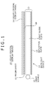
- FIG. 1 An exploded side view showing a schematic configuration of a liquid crystal display device according to an embodiment.
- FIG. 2 A cross-sectional view showing a main portion of a prism sheet as a light control element according to an embodiment.
- FIG. 3 An enlarged view of the prism portions forming the prism sheet shown in FIG. 2 .
- FIG. 4 Drawings showing changes in the range of output angle of light reflected by total reflection on a second prism surface, under varied profile of the second prism surface of the prism portions.
- FIG. 5 Results of simulation of output viewing angle compared among a plurality of prism portions differed in profile of the second prism surface.
- FIG. 6 Results of simulation showing an example of intensity distribution of the prism portion.
- FIG. 7 A drawing showing exemplary profiles of the second prism surface of the samples used for simulation shown in FIG. 6 .
- FIG. 8 A drawing showing relations between angle of inclination ⁇ 2 of the reference oblique side of the second prism surface of the prism portion and the position of center of gravity of intensity distribution.
- FIG. 9 An enlarged view of a prism portion showing an exemplary modified embodiment.
- FIG. 10 A schematic side view showing an exemplary configuration of a conventional prism sheet.
- FIG. 1 is an exploded side view showing a schematic configuration of a liquid crystal display device 10 according to an embodiment.
- a liquid crystal display device 10 is constructed with a backlight device 12 as a surface light source device, and a liquid crystal display panel 16 .
- the backlight device 12 has a backlight unit 13 , and a prism sheet 11 as a light control element according to the present invention.
- Other optical elements such as a diffuser sheet, a polarization splitter sheet or the like, may additionally be disposed between the prism sheet 11 and the liquid crystal display panel 16 .
- the backlight unit 13 is configured as the edge light type, having a light guide plate 2 made of a translucent material, and a light source 15 disposed at one side end portion of the light guide plate 2 , and a reflector plate 14 disposed on the back face side (bottom face side in the drawing) of the light guide plate 2 .
- a linear light source such as CCFL, or a single or a plurality of point light source such as LED, are used as the light source 15 .
- the light guide plate 2 is made of an injection-molded product of a colorless, transparent resin allowing transmission of light in the wavelength region of the light used for the light source, such as acrylic resins, methacrylic resins, styrene resins, polycarbonate resins and so forth.
- the top surface of the light guide plate 2 is given as a plane of output 2 a allowing light from the light source 15 to output therethrough, and constructed such that the light is output with a predetermined range of output angle (central angle ⁇ ) towards the prism sheet 11 side.
- the reflector plate 14 has a metal foil of silver, aluminum or the like, or a white coated film, provided on the inner surface side thereof opposed to the light guide plate 2 , and functions to reflect the light leaked from the light guide plate 2 or reflected on the prism sheet 11 towards the front direction (upward in the drawing).
- the prism sheet 11 has a function of adjusting angular intensity distribution of the light output from the backlight unit 13 , and of allowing the light to be output towards a side of the liquid crystal display panel 16 at a certain output viewing angle.
- the light output from the prism sheet 11 is entering the liquid crystal display panel 16 .
- the liquid crystal display panel 16 displays an image on the screen while performing control of modulating the light pixel by pixel.
- the prism sheet 11 has a surface, given as the plane of incidence, on one side opposed to the light guide plate 2 , and the other surface, given as the plane of output allowing the light to output therethrough, on the other side opposed to the liquid crystal display panel 16 .
- a number of prism portions 11 P are arrayed in parallel, in the direction from one side end portion of the light guide plate 2 , where the light source 15 is disposed, towards the other side end portion opposed thereto.
- FIG. 2 is an enlarged cross-sectional view of the prism sheet 11 .
- the prism portion 11 P of the present embodiment has a structure such that a triangular-sectioned prism component has a curved profile on one prism surface thereof.
- One prism surface 11 a of the prism portion 11 P is given as a flat-profiled first prism surface which serves as a plane of incidence of light output from the plane of output 2 a of the light guide plate 2
- the other prism surface 11 b of the prism portion 11 P is given as a curved second prism surface which allows light entering through the first prism surface 11 a to totally reflect on the inner surface side thereof.
- the second prism surface 11 b has an outwardly swelled curved profile.
- the profile being outwardly swelled, and the light entering through the first prism surface 11 a is reflected by total reflection and deflected towards the front direction (direction towards the liquid crystal display panel 16 ).
- the deflected light is output out from a plane of output 11 S at a predetermined output viewing angle ⁇ .
- FIG. 3 is an enlarged view of the profile of the prism portion 11 P.
- the prism portion 11 P is constructed using as a reference a virtual prism component having a cross-section of triangle OAB having one apex O and two bases A, B.
- the first prism surface 11 a corresponds to one oblique side OA of triangle OAB
- the second prism surface 11 b is formed by a curved profile swelled out from the other oblique side OB of triangle OAB at a curvature of a predetermined level or larger.
- triangle OAB is a triangle where an angle between oblique side OA and perpendicular OS through point O fallen on AB is ⁇ 1 ; an angle between oblique side OB and the segment OS is ⁇ 2 ; distance X 1 between A and S is approximately 10 ⁇ m; and distance X 2 between B and S is approximately 9 ⁇ m.
- the prism portion 11 P has the first prism surface 11 a with a linear form corresponded to segment OA, and the second prism surface 11 b with an arc form passing through point O and point B.
- height H (corresponded to length of segment OS) is approximately 16 ⁇ m
- pitch of array (distance between the apexes of the adjacent prism portions, corresponds to the sum of X 1 and X 2 ) is approximately 19 ⁇ m.
- sizes of X 1 , X 2 and H are not limited to those exemplified in the above.
- the pitch of array may be adjustable by similarity transformation (similarity shrinkage, similarity expansion).
- FIG. 10 shows a prism sheet 1 having on the lower surface thereof triangular-sectioned prisms 1 P arrayed at a constant pitch.
- “2” is a light guide plate, on the left side of which in the drawing, a light source (not shown) is disposed.
- the light guide plate 2 is designed so as to make angle of light extracted from the plane of output 2 a shallow (so as to reduce angle ⁇ ).
- Each prism 1 P of the prism sheet 1 has a certain apex angle ⁇ .
- the prism 1 P allows light L output from the plane of output 2 a of the light guide plate 2 at a shallow angle to enter through one prism surface 1 a thereof, and to totally reflect on the inner surface side of the other prism surface 1 b , to thereby raise the light vertically upward (to the front direction of the liquid crystal display panel).
- apex angle ⁇ of prism Various values of the apex angle ⁇ of prism have been known under the specification, and 63° is a representative angle. Assuming now refractive index of the prism sheet as approximately 1.59, the output angle (central angle) ⁇ from the light guide plate 2 allowing the light L to be raised up vertically upward will be approximately 31°.
- the curved surface forming the second prism surface 11 b is formed with a curvature, which ensures an output viewing angle (second output viewing angle) wider than an output viewing angle (first output viewing angle) of a case where the second prism surface is flat. Details will be explained below.
- FIG. 4 shows changes in the output angle of light reflected by total reflection on the inner surface of the second prism surface, observed when the profile of the second prism surface was varied.
- FIG. 4A shows a prism portion P 1 (corresponded to the prism 1 P shown in FIG. 10 ) having a flat second prism surface Pb
- FIGS. 4B and 4C show prism portions P 2 , P 3 having curved second prism surfaces Pb.
- the light L entering through a first prism surface Pa is reflected by total reflection on the inner side of the second prism surface Pb, and output out from the plane of output of the prism sheet.
- a range of output angle (output viewing angle) ⁇ 1 of light reflected by total reflection on the second prism surface Pb corresponds to a range of incidence angle of light with respect to the first prism surface Pa.
- the second prism surface Pb is given as arc, as shown in FIG.
- the range of output angle ⁇ 2 of light reflected by total reflection on the second prism surface Pb will be narrowed up to a predetermined range of curvature of an arc surface, and thereby condensation performance is enhanced as compared with the case shown in FIG. 4A .
- the curvature of the second prism surface Pb is increased to a predetermined level or larger, as shown in FIG. 4C , the range of output angle ⁇ 3 of light reflected by total reflection on the second prism surface Pb will be widened as compared with the case shown in FIG. 4A .
- the second prism surface Pb is formed with a radius of curvature ensuring an output viewing angle (second output viewing angle) wider than an output viewing angle (first output viewing angle) of a case where the second prism surface Pb is flat.
- FIG. 5 comparatively shows results of simulation comparing output viewing angle obtained from a plurality of prism portions differed in profile of the first prism surface.
- the axis of abscissa of FIG. 5 represents ratio (R/H) of radius of curvature R [ ⁇ m] and height of prism portion H [ ⁇ m] of a second prism surface formed with a curved profile, and the axis of ordinate represents the viewing angle.
- the viewing angle herein means a range of angle with a relative intensity of 0.5 or larger while assuming an intensity peak value of 1.
- the viewing angle corresponds to the output viewing angle ⁇ shown in FIG. 2 .
- Sample 3 is modified from sample 4 so as to form the first prism surface with an outwardly-swelled curved profile.
- Each of samples 1 to 4 contains a group of samples varied in the radius of curvature R of the second prism surface in 7 ways, with respect to prism height H obtained while fixing the pitch of array of prisms (X 1 +X 2 ) under the condition of ⁇ 1 , as shown by the individual plots on the kinked lines shown in FIG. 5 .
- the viewing angle is 24° assuming that the second prism surface is a flat surface (corresponded to straight line OB in FIG. 3 ). Accordingly, the range of R/H, capable of ensuring that the output viewing angle (second output viewing angle) is wider than the output viewing angle (first output viewing angle) of a case where the second prism surface is flat, will be given as 1.1 ⁇ R/H ⁇ 5.0.
- R/H>1.1 The reason why R/H>1.1 was given is that, if R/H has a value of 1.1 or smaller, the base angle of the prism portion on the second prism surface side ( ⁇ OBA in FIG. 3 ) will be as close as 90° or will be 90° or larger, reducing a region capable of deflecting the light frontward, and preventing improvement of the luminance. Another reason is that manufacture of the prism portion having such a profile may be difficult.
- FIG. 6 shows results of simulation of luminance distribution of the prism portion ensuring viewing angles of 60° and 50°.
- the axis of abscissa represents direction of output of light, wherein 90° corresponds to the front direction.
- the axis of ordinate represents relative intensity assuming intensity observed in the front direction for the case where isosceles triangular prism components (63 prisms) having an apex angle of 63° were used as 1.
- FIG. 7 shows profiles of the second prism surface of the prism portions ensuring viewing angles of 60° and 50°.
- the pitch of array of the prism portions may be altered by modifying setting of ⁇ 2 .
- position of the center of gravity in the intensity distribution may be adjustable by varying a value of angle ⁇ 2 .
- FIG. 8 shows relations between angle ⁇ 2 and position (angle) of center of gravity of intensity in the various samples differed in R/H value of the prism portion. As is clear from FIG. 8 , position of center of gravity of intensity distribution shifts towards the higher angle side as the angle ⁇ 2 increases. Because the center of gravity of intensity distribution may arbitrarily be varied by adjusting the angle ⁇ 2 , luminance characteristics adapted to specification and so forth of the devices may be more readily designed.
- prism sheet 11 of the present embodiment is made of transparent film or sheet made of, for example, polycarbonate, polyvinyl, acrylic resin, polyamide, polyethylene terephthalate, poly- ⁇ -olefin, cellulose resin, glass, etc, all having optical transparency.
- Each prism portion 11 P may be formed on the surface of these transparent films as being integrated therewith, or a layer having the prism portions 11 P formed thereon may be placed on these transparent films and may be integrated in the later process.
- Methods of forming the prism sheet 11 are not specifically limited, and other methods
- mold forming using heat pressing such as mold forming using ultraviolet curable resin, and continuous molding such as fusion extrusion, etc, may be utilized.
- the output viewing angle (second output viewing angle) of light output from the plane of output 11 S after being reflected by total reflection on the second prism surface 11 b may be made wider than the output viewing angle (first output viewing angle) of a case where the second prism surface is flat.
- a light control element having both of a desired viewing angle and luminance distribution characteristics may readily be designed and manufactured, by arbitrarily adjusting the profile (angle ⁇ 2 , radius of curvature R, height H) of the second prism surface 11 b .
- the second prism surface is formed based on a continuous curved profile, the visibility over a wide viewing angle may be improved without causing non-uniformity in intensity distribution of output light.
- the backlight device 12 of the present embodiment has thus-structured prism sheet 11 set over the light guide plate 2 . Accordingly, the viewing angle characteristics may be improved as compared with the conventional backlight device having a triangular-sectioned prism sheet, and furthermore a surface light source device having both of desired viewing angle and luminance distribution characteristics may be constructed.
- liquid crystal display device 10 of the present embodiment may provide such an image quality suitable for viewing by many people from wide angles by virtue of thus-structured backlight device 12 .
- the range of output angle of light output from the prism sheet 11 was adjusted by setting ratio (R/H) of the radius of curvature of the second prism surface 11 b and height of the prism portion 11 P.
- angle of inclination ⁇ 1 of the first prism surface 11 a which serves as the plane of incidence of light, may be added to the design parameters.
- the angle of incidence of light to the inner surface of the second prism surface 11 b changes, and thereby the output viewing angle of light can be controlled.
- the first prism surface 11 a of the prism portion 11 P having been described in the above embodiment as being a linear and flat surface, is not limited thereto, and may have a curved profile.
- the first prism surface can now function as a lens surface, thereby an aperture effect of incident light may be obtained, and directivity of light incident on the second prism surface 11 b may be improved.
- the second prism surface 11 b of the prism portion 11 P in the above embodiment was formed with a single curved profile of a radius of curvature R, whereas the second prism surface may be formed with a composite curved profile having a plurality of radii of curvature.
- the example may be adoptable to adjustment of profile on the base B side of the second prism surface 11 b , as shown in FIG. 9 .
- the degree of freedom in designing the output viewing angle and position of center of gravity of intensity distribution may be improved.
- An specific exemplary design is such that a portion of inclined surface between apex O and a midpoint to base B is formed with a common radius of curvature R, and a portion between the midpoint to base B is formed with a radius of curvature R 1 smaller than R, or a radius of curvature R 2 larger than R.
Landscapes
- Physics & Mathematics (AREA)
- General Physics & Mathematics (AREA)
- Optics & Photonics (AREA)
- Nonlinear Science (AREA)
- Mathematical Physics (AREA)
- Chemical & Material Sciences (AREA)
- Crystallography & Structural Chemistry (AREA)
- Planar Illumination Modules (AREA)
- Optical Elements Other Than Lenses (AREA)
- Liquid Crystal (AREA)
- Light Guides In General And Applications Therefor (AREA)
Abstract
Description
Claims (6)
Applications Claiming Priority (4)
| Application Number | Priority Date | Filing Date | Title |
|---|---|---|---|
| JP2007009781A JP2008177070A (en) | 2007-01-19 | 2007-01-19 | Optical control element, planar light source device, and liquid crystal display device |
| JP2007-009781 | 2007-01-19 | ||
| JPP2007-009781 | 2007-01-19 | ||
| PCT/JP2008/050551 WO2008088029A1 (en) | 2007-01-19 | 2008-01-17 | Light control element, surface light source device and liquid crystal display |
Publications (2)
| Publication Number | Publication Date |
|---|---|
| US20090207341A1 US20090207341A1 (en) | 2009-08-20 |
| US8059229B2 true US8059229B2 (en) | 2011-11-15 |
Family
ID=39636030
Family Applications (1)
| Application Number | Title | Priority Date | Filing Date |
|---|---|---|---|
| US12/293,521 Expired - Fee Related US8059229B2 (en) | 2007-01-19 | 2008-01-17 | Light control element, surface light source device and liquid crystal display device |
Country Status (7)
| Country | Link |
|---|---|
| US (1) | US8059229B2 (en) |
| EP (1) | EP2058588A4 (en) |
| JP (1) | JP2008177070A (en) |
| KR (1) | KR101448047B1 (en) |
| CN (1) | CN101542194A (en) |
| TW (1) | TW200846713A (en) |
| WO (1) | WO2008088029A1 (en) |
Cited By (5)
| Publication number | Priority date | Publication date | Assignee | Title |
|---|---|---|---|---|
| US9964686B2 (en) | 2016-04-19 | 2018-05-08 | Samsung Display Co., Ltd. | Display apparatus |
| US10012356B1 (en) | 2017-11-22 | 2018-07-03 | LightLouver LLC | Light-redirecting optical daylighting system |
| US10371350B2 (en) | 2014-04-01 | 2019-08-06 | 3M Innovative Properties Company | Asymmetric turning film with multiple light sources |
| US10388230B2 (en) | 2014-05-30 | 2019-08-20 | 3M Innovative Properties Company | Temporally multiplexing backlight with asymmetric turning film |
| US10948650B2 (en) | 2015-08-13 | 2021-03-16 | 3M Innovative Properties Company | Display including turning film and diffuser |
Families Citing this family (20)
| Publication number | Priority date | Publication date | Assignee | Title |
|---|---|---|---|---|
| TWI414673B (en) * | 2009-12-08 | 2013-11-11 | Ind Tech Res Inst | Light guide microstructure plate, light guiding method, and application on window structure |
| JP5360592B2 (en) * | 2009-12-28 | 2013-12-04 | 大日本印刷株式会社 | Prism sheet, surface light source device and display device |
| CN102252271A (en) * | 2010-05-17 | 2011-11-23 | 财团法人工业技术研究院 | Light-guiding microstructure sheet, light-guiding method and window structure |
| CN102959313B (en) * | 2010-06-24 | 2015-07-08 | 东洋苯乙烯股份有限公司 | Light-guiding plate made of styrenic resin |
| JP5682232B2 (en) * | 2010-10-29 | 2015-03-11 | ソニー株式会社 | Liquid crystal light control device and imaging apparatus |
| US20140085570A1 (en) * | 2011-05-31 | 2014-03-27 | Mitsubishi Electric Corporation | Backlight and liquid crystal display device |
| KR101898471B1 (en) * | 2012-03-12 | 2018-09-14 | 삼성디스플레이 주식회사 | Light guide plate and display device having the same |
| JP6071737B2 (en) * | 2013-05-08 | 2017-02-01 | 富士フイルム株式会社 | Liquid crystal display |
| KR102135918B1 (en) * | 2013-12-20 | 2020-07-20 | 엘지디스플레이 주식회사 | Liquid crystal display device having backlight unit to be able to control viewing angle |
| JP2015191181A (en) * | 2014-03-28 | 2015-11-02 | 大日本印刷株式会社 | Surface light source device and display device |
| CN104090411B (en) * | 2014-06-19 | 2017-02-15 | 京东方科技集团股份有限公司 | Liquid crystal display panel |
| CN104391346A (en) * | 2014-07-22 | 2015-03-04 | 翰博高新材料(合肥)股份有限公司 | Prism film in visual angle deflection structure |
| CN104696876B (en) * | 2015-04-02 | 2017-07-04 | 江苏双星彩塑新材料股份有限公司 | Diaphragm and backlight module and liquid crystal display with the diaphragm are widened in visual angle |
| KR101730822B1 (en) * | 2015-06-22 | 2017-05-11 | 주식회사 엘엠에스 | Optical Sheet Module And Back Light Unit Using The Same |
| DE112016002852T5 (en) * | 2015-06-26 | 2018-03-08 | Merck Patent Gmbh | Liquid crystal medium containing polymerizable compounds |
| CN104965342B (en) * | 2015-07-08 | 2017-09-29 | 京东方科技集团股份有限公司 | A kind of display device |
| CN106391508B (en) * | 2016-08-31 | 2019-07-09 | 合肥泰禾光电科技股份有限公司 | A kind of camera aligning tool of the included backlight for color selector |
| CN106772725A (en) * | 2016-12-30 | 2017-05-31 | 张家港康得新光电材料有限公司 | light turning film and laminated glass |
| WO2018235803A1 (en) * | 2017-06-19 | 2018-12-27 | シャープ株式会社 | Daylighting member and daylighting device |
| JP7271241B2 (en) * | 2018-11-02 | 2023-05-11 | 株式会社小糸製作所 | vehicle lamp |
Citations (8)
| Publication number | Priority date | Publication date | Assignee | Title |
|---|---|---|---|---|
| US4505551A (en) * | 1977-03-10 | 1985-03-19 | Transamerica Delaval Inc. | Illumination and light gate utilization methods and apparatus |
| US6474827B2 (en) * | 1995-10-13 | 2002-11-05 | Omron Corporation | Image display apparatus |
| JP2004006245A (en) | 2002-01-18 | 2004-01-08 | Mitsubishi Rayon Co Ltd | Light source device |
| WO2004015330A1 (en) | 2002-08-09 | 2004-02-19 | Mitsubishi Rayon Co., Ltd. | Flat light source device |
| US20040207775A1 (en) * | 2003-04-16 | 2004-10-21 | Samsung Electronics Co., Ltd. | Light guide panel of edge-light type backlight system and edge-light type backlight system employing the same |
| US20050041410A1 (en) * | 2002-01-18 | 2005-02-24 | Tomoyoshi Yamashita | Light source device |
| US7710512B2 (en) * | 2006-05-09 | 2010-05-04 | Lg Electronics Inc. | Prism sheet, backlight unit and liquid crystal display |
| US20100208170A1 (en) * | 2007-10-29 | 2010-08-19 | Omron Corporation | Surface light source device and liquid crystal display device |
Family Cites Families (12)
| Publication number | Priority date | Publication date | Assignee | Title |
|---|---|---|---|---|
| JPH0618879A (en) | 1991-12-27 | 1994-01-28 | Mitsubishi Rayon Co Ltd | Surface light source element |
| JPH07325208A (en) | 1994-05-31 | 1995-12-12 | Canon Inc | Prism sheet, liquid crystal display device having this prism sheet and information transmission device having this liquid crystal display device |
| JP4011287B2 (en) * | 2000-12-25 | 2007-11-21 | 株式会社エンプラス | Light control sheet, surface light source device, and liquid crystal display |
| TWI258023B (en) * | 2001-11-07 | 2006-07-11 | Ibm | A prism sheet, a back-light unit using said prism sheet, and a transmission type liquid crystal display device |
| JP4035998B2 (en) * | 2002-01-23 | 2008-01-23 | オムロン株式会社 | Surface light source device, diffusion plate, and liquid crystal display device |
| KR100712766B1 (en) * | 2002-01-31 | 2007-05-02 | 미츠비시 레이온 가부시키가이샤 | Light source apparatus |
| JP4889130B2 (en) * | 2002-03-15 | 2012-03-07 | 三菱レイヨン株式会社 | Optical deflection element and surface light source device |
| TW594108B (en) * | 2002-06-24 | 2004-06-21 | Mitsubishi Rayon Co | Light source device and light deflection element |
| CN100426011C (en) * | 2003-03-03 | 2008-10-15 | 三菱丽阳株式会社 | Optical deflector element and light source device |
| JP4544517B2 (en) * | 2003-07-15 | 2010-09-15 | 三菱レイヨン株式会社 | Light source device |
| JP2005243259A (en) * | 2004-02-24 | 2005-09-08 | Omron Corp | Double-screen image display device and surface light source device |
| JP2006107997A (en) * | 2004-10-07 | 2006-04-20 | Mitsubishi Electric Corp | Surface light source device and liquid crystal display device |
-
2007
- 2007-01-19 JP JP2007009781A patent/JP2008177070A/en active Pending
-
2008
- 2008-01-15 TW TW097101535A patent/TW200846713A/en unknown
- 2008-01-17 KR KR1020087022928A patent/KR101448047B1/en active IP Right Grant
- 2008-01-17 EP EP08703405A patent/EP2058588A4/en not_active Withdrawn
- 2008-01-17 CN CNA2008800001219A patent/CN101542194A/en active Pending
- 2008-01-17 US US12/293,521 patent/US8059229B2/en not_active Expired - Fee Related
- 2008-01-17 WO PCT/JP2008/050551 patent/WO2008088029A1/en active Application Filing
Patent Citations (10)
| Publication number | Priority date | Publication date | Assignee | Title |
|---|---|---|---|---|
| US4505551A (en) * | 1977-03-10 | 1985-03-19 | Transamerica Delaval Inc. | Illumination and light gate utilization methods and apparatus |
| US6474827B2 (en) * | 1995-10-13 | 2002-11-05 | Omron Corporation | Image display apparatus |
| JP2004006245A (en) | 2002-01-18 | 2004-01-08 | Mitsubishi Rayon Co Ltd | Light source device |
| US20050041410A1 (en) * | 2002-01-18 | 2005-02-24 | Tomoyoshi Yamashita | Light source device |
| WO2004015330A1 (en) | 2002-08-09 | 2004-02-19 | Mitsubishi Rayon Co., Ltd. | Flat light source device |
| US20050248960A1 (en) | 2002-08-09 | 2005-11-10 | Tomoyoshi Yamashita | Flat light source device |
| US7201510B2 (en) * | 2002-08-09 | 2007-04-10 | Mitsubishi Rayon Co., Ltd. | Edge lighted device with polarization |
| US20040207775A1 (en) * | 2003-04-16 | 2004-10-21 | Samsung Electronics Co., Ltd. | Light guide panel of edge-light type backlight system and edge-light type backlight system employing the same |
| US7710512B2 (en) * | 2006-05-09 | 2010-05-04 | Lg Electronics Inc. | Prism sheet, backlight unit and liquid crystal display |
| US20100208170A1 (en) * | 2007-10-29 | 2010-08-19 | Omron Corporation | Surface light source device and liquid crystal display device |
Cited By (6)
| Publication number | Priority date | Publication date | Assignee | Title |
|---|---|---|---|---|
| US10371350B2 (en) | 2014-04-01 | 2019-08-06 | 3M Innovative Properties Company | Asymmetric turning film with multiple light sources |
| US10388230B2 (en) | 2014-05-30 | 2019-08-20 | 3M Innovative Properties Company | Temporally multiplexing backlight with asymmetric turning film |
| US10948650B2 (en) | 2015-08-13 | 2021-03-16 | 3M Innovative Properties Company | Display including turning film and diffuser |
| US9964686B2 (en) | 2016-04-19 | 2018-05-08 | Samsung Display Co., Ltd. | Display apparatus |
| US10012356B1 (en) | 2017-11-22 | 2018-07-03 | LightLouver LLC | Light-redirecting optical daylighting system |
| US10119667B1 (en) | 2017-11-22 | 2018-11-06 | LightLouver LLC | Light-redirecting optical daylighting system |
Also Published As
| Publication number | Publication date |
|---|---|
| TW200846713A (en) | 2008-12-01 |
| KR20090100225A (en) | 2009-09-23 |
| CN101542194A (en) | 2009-09-23 |
| KR101448047B1 (en) | 2014-10-07 |
| JP2008177070A (en) | 2008-07-31 |
| EP2058588A1 (en) | 2009-05-13 |
| US20090207341A1 (en) | 2009-08-20 |
| EP2058588A4 (en) | 2012-01-18 |
| WO2008088029A1 (en) | 2008-07-24 |
Similar Documents
| Publication | Publication Date | Title |
|---|---|---|
| US8059229B2 (en) | Light control element, surface light source device and liquid crystal display device | |
| US7367705B2 (en) | Long curved wedges in an optical film | |
| US7153017B2 (en) | Light deflection element and light source apparatus using the same | |
| KR101617485B1 (en) | Optical component, lighting device, and display device | |
| TWI417578B (en) | Turning film using array of roof prism | |
| EP2159483A2 (en) | Liquid crystal display | |
| JP2012164583A (en) | Light guide plate, surface light source device, and transmission type display device | |
| JP5310199B2 (en) | Optical sheet, backlight unit and display device | |
| WO2008029911A1 (en) | Planar light source element, light control member using the same, and image display device using the same | |
| JPWO2008047794A1 (en) | LIGHTING DEVICE AND IMAGE DISPLAY DEVICE USING THE SAME | |
| JP4815930B2 (en) | Light transmissive film, backlight device, and liquid crystal display device | |
| TW200402560A (en) | Planar light source apparatus and light guide used therein | |
| JP4684838B2 (en) | LIGHTING DEVICE, LIGHT CONTROL MEASUREMENT STRUCTURE AND IMAGE DISPLAY DEVICE USING THEM | |
| JP2009123397A (en) | Illumination device, and image display device using it | |
| CN114089464B (en) | Light guide plate with gradual change microstructure and light source module thereof | |
| JP2008233708A (en) | Diffusion plate with double-sided configuration | |
| JP4563294B2 (en) | Light control member provided in illumination device and image display device using the same | |
| JP4689543B2 (en) | LIGHTING DEVICE, LIGHT CONTROL MEMBER INCLUDING THE SAME, AND IMAGE DISPLAY DEVICE USING THE SAME | |
| US11099431B2 (en) | Edge type backlight unit and display device including the same | |
| US8870399B2 (en) | Backlight unit comprising condensing film having hetero-conic lenses | |
| JP5195069B2 (en) | Backlight unit and display device | |
| JP5311034B2 (en) | Light source device, backlight unit, and display device | |
| JP2011150078A (en) | Optical sheet, backlight unit and display apparatus | |
| JP2021170491A (en) | Side edge type surface lighting device | |
| JP4485416B2 (en) | Light deflection element and light source device |
Legal Events
| Date | Code | Title | Description |
|---|---|---|---|
| AS | Assignment |
Owner name: SONY CORPORATION, JAPAN Free format text: ASSIGNMENT OF ASSIGNORS INTEREST;ASSIGNORS:SHINKAI, SHOGO;KUDO, YASUYUKI;AOKI, MAKOTO;AND OTHERS;REEL/FRAME:022163/0394;SIGNING DATES FROM 20090108 TO 20090115 Owner name: SONY CORPORATION, JAPAN Free format text: ASSIGNMENT OF ASSIGNORS INTEREST;ASSIGNORS:SHINKAI, SHOGO;KUDO, YASUYUKI;AOKI, MAKOTO;AND OTHERS;SIGNING DATES FROM 20090108 TO 20090115;REEL/FRAME:022163/0394 |
|
| ZAAA | Notice of allowance and fees due |
Free format text: ORIGINAL CODE: NOA |
|
| ZAAB | Notice of allowance mailed |
Free format text: ORIGINAL CODE: MN/=. |
|
| STCF | Information on status: patent grant |
Free format text: PATENTED CASE |
|
| FEPP | Fee payment procedure |
Free format text: PAYOR NUMBER ASSIGNED (ORIGINAL EVENT CODE: ASPN); ENTITY STATUS OF PATENT OWNER: LARGE ENTITY |
|
| FPAY | Fee payment |
Year of fee payment: 4 |
|
| AS | Assignment |
Owner name: SATURN LICENSING LLC, NEW YORK Free format text: ASSIGNMENT OF ASSIGNORS INTEREST;ASSIGNOR:SONY CORPORATION;REEL/FRAME:043177/0794 Effective date: 20170613 |
|
| MAFP | Maintenance fee payment |
Free format text: PAYMENT OF MAINTENANCE FEE, 8TH YEAR, LARGE ENTITY (ORIGINAL EVENT CODE: M1552); ENTITY STATUS OF PATENT OWNER: LARGE ENTITY Year of fee payment: 8 |
|
| FEPP | Fee payment procedure |
Free format text: MAINTENANCE FEE REMINDER MAILED (ORIGINAL EVENT CODE: REM.); ENTITY STATUS OF PATENT OWNER: LARGE ENTITY |
|
| LAPS | Lapse for failure to pay maintenance fees |
Free format text: PATENT EXPIRED FOR FAILURE TO PAY MAINTENANCE FEES (ORIGINAL EVENT CODE: EXP.); ENTITY STATUS OF PATENT OWNER: LARGE ENTITY |
|
| STCH | Information on status: patent discontinuation |
Free format text: PATENT EXPIRED DUE TO NONPAYMENT OF MAINTENANCE FEES UNDER 37 CFR 1.362 |
|
| FP | Lapsed due to failure to pay maintenance fee |
Effective date: 20231115 |