US8060081B2 - Remote battery replacement notification system and method - Google Patents
Remote battery replacement notification system and method Download PDFInfo
- Publication number
- US8060081B2 US8060081B2 US12/255,298 US25529808A US8060081B2 US 8060081 B2 US8060081 B2 US 8060081B2 US 25529808 A US25529808 A US 25529808A US 8060081 B2 US8060081 B2 US 8060081B2
- Authority
- US
- United States
- Prior art keywords
- battery
- subscriber
- transceiver
- support system
- replace
- Prior art date
- Legal status (The legal status is an assumption and is not a legal conclusion. Google has not performed a legal analysis and makes no representation as to the accuracy of the status listed.)
- Expired - Fee Related, expires
Links
- 238000000034 method Methods 0.000 title claims description 23
- 230000004044 response Effects 0.000 claims description 14
- 230000003287 optical effect Effects 0.000 claims description 6
- 230000000737 periodic effect Effects 0.000 claims 1
- 238000010586 diagram Methods 0.000 description 8
- 239000000835 fiber Substances 0.000 description 6
- 230000008520 organization Effects 0.000 description 5
- 230000008569 process Effects 0.000 description 5
- 230000004075 alteration Effects 0.000 description 2
- 230000008859 change Effects 0.000 description 2
- 230000004048 modification Effects 0.000 description 2
- 238000012986 modification Methods 0.000 description 2
- 230000008571 general function Effects 0.000 description 1
- 238000009434 installation Methods 0.000 description 1
Images


Classifications
-
- H—ELECTRICITY
- H04—ELECTRIC COMMUNICATION TECHNIQUE
- H04M—TELEPHONIC COMMUNICATION
- H04M19/00—Current supply arrangements for telephone systems
- H04M19/08—Current supply arrangements for telephone systems with current supply sources at the substations
-
- H—ELECTRICITY
- H04—ELECTRIC COMMUNICATION TECHNIQUE
- H04W—WIRELESS COMMUNICATION NETWORKS
- H04W52/00—Power management, e.g. TPC [Transmission Power Control], power saving or power classes
- H04W52/02—Power saving arrangements
- H04W52/0209—Power saving arrangements in terminal devices
- H04W52/0261—Power saving arrangements in terminal devices managing power supply demand, e.g. depending on battery level
- H04W52/0296—Power saving arrangements in terminal devices managing power supply demand, e.g. depending on battery level switching to a backup power supply
-
- Y—GENERAL TAGGING OF NEW TECHNOLOGICAL DEVELOPMENTS; GENERAL TAGGING OF CROSS-SECTIONAL TECHNOLOGIES SPANNING OVER SEVERAL SECTIONS OF THE IPC; TECHNICAL SUBJECTS COVERED BY FORMER USPC CROSS-REFERENCE ART COLLECTIONS [XRACs] AND DIGESTS
- Y02—TECHNOLOGIES OR APPLICATIONS FOR MITIGATION OR ADAPTATION AGAINST CLIMATE CHANGE
- Y02D—CLIMATE CHANGE MITIGATION TECHNOLOGIES IN INFORMATION AND COMMUNICATION TECHNOLOGIES [ICT], I.E. INFORMATION AND COMMUNICATION TECHNOLOGIES AIMING AT THE REDUCTION OF THEIR OWN ENERGY USE
- Y02D30/00—Reducing energy consumption in communication networks
- Y02D30/70—Reducing energy consumption in communication networks in wireless communication networks
Definitions
- the present invention relates to communication systems and more particularly to a remote battery replacement notification system and method.
- Fiber optics and wireless channels are not designed to carry power as Plain Old Telephone Service (POTS) does presently.
- POTS Plain Old Telephone Service
- subscriber units at a customer's location may be locally powered with battery back-up.
- the battery back-up will maintain continuous service of the telecommunication services during a commercial power failure.
- the batteries have a long but finite lifetime and the customer may not remember to check their batteries. Failure to replace the batteries will result in the customer losing their telecommunication services during power outage.
- FIG. 1 is a block diagram of a remote battery replacement notification system in accordance with one embodiment of the invention
- FIG. 2 is a block diagram of a remote battery replacement notification system in accordance with one embodiment of the invention.
- FIG. 3 is a block diagram of a subscriber unit in accordance with one embodiment of the invention.
- FIG. 4 is a block diagram of a remote battery replacement notification system in accordance with one embodiment of the invention.
- FIG. 5 is a flow chart of the steps used in a remote battery replacement notification method in accordance with one embodiment of the invention.
- FIGS. 6 & 7 are a flow chart of the steps used in a remote battery replacement notification method in accordance with one embodiment of the invention.
- a remote battery replacement notification system for a communication system includes a subscriber unit having a battery.
- An operational support system is in communication with the subscriber unit. The operational support system periodically polls the subscriber unit.
- a compact service node is in communication with the subscriber unit. The compact service node sends a replace battery notification to the subscriber unit when a replace battery message is received from the operational support system.
- FIG. 1 is a block diagram of a remote battery replacement notification system 10 in accordance with one embodiment of the invention.
- the system 10 has a subscriber unit 12 having a battery 14 .
- An operational support system 16 is in communication with the subscriber unit 12 .
- the operational support system periodically polls the subscriber unit 12 .
- a compact service node 18 is in communication with the subscriber unit 12 .
- the compact service node 18 sends a replace battery notification to the subscriber unit 12 when a replace battery message is received from the operational support system 16 .
- FIG. 2 is a block diagram of a remote battery replacement notification system 30 in accordance with one embodiment of the invention.
- the system 30 has a subscriber unit 32 . Commonly the subscriber unit would be attached to the outside of a subscriber's residence.
- the subscriber unit 32 has a transceiver 34 connected to an antenna 36 .
- a battery 38 is connected to the transceiver 34 and to a line power input 40 . The battery 38 is used when there is a commercial power outage.
- a wireless access node 42 has a wireless connection 44 with the transceiver 34 of the subscriber unit 32 .
- An optical network unit 46 is connected to the wireless access node 42 .
- the optical network unit 46 converts a fiber optic signal to an electrical or RF signal.
- a switch 48 is connected to the optical network unit 46 .
- the switch 48 may be a circuit switch or a packet switch.
- An operational support system 50 is connected to the switch 48 .
- the operational support system 50 periodically polls the subscriber unit 32 .
- the general function of the operational support system 50 is to monitor the integrity of the links (phone lines).
- a compact service node 52 is connected to the switch 48 .
- the compact service node 52 sends a replace battery notification to the subscriber unit 32 when a replace battery message is received from the operational support system 50 .
- a battery replacement service center 54 is connected to the operational support system 50 .
- the battery replacement service center 54 may send out a service person to replace the battery for the subscriber.
- FIG. 3 is a block diagram of a subscriber unit 70 in accordance with one embodiment of the invention.
- the subscriber unit 70 has a transceiver 72 connected to an antenna 74 .
- the transceiver 72 is connected to a fiber optic cable 76 .
- a telephone plug (POTS jack) 78 is connected to a transceiver 72 .
- a cable TV (CATV) output 80 is connected to a transceiver 72 .
- An internet output 82 is connected to a transceiver 72 .
- the transceiver 72 is connected to a power supply 84 .
- the power supply 84 conditions the line power 86 .
- a switch 88 switches the transceiver 72 to battery 90 power when a power outage is detected. In one embodiment, the power supply acts a battery charging circuit.
- FIG. 4 is a block diagram of a remote battery replacement notification system 100 in accordance with one embodiment of the invention.
- a residence 102 has a subscriber unit 104 with a battery.
- the subscriber unit 104 is connected to a residential gateway 106 .
- the residential gateway provides an in-house wireless connections to a computer 108 , a telephone 110 and a television 112 .
- the subscriber unit is connected to a wireless network access node 114 .
- An Optical Network Unit (ONU) 116 is connected to the wireless network access node 114 .
- a fiber optic cable 118 connects the ONU 116 to a central office 120 .
- the central office 120 has a switch 122 and a central office terminal (COT) 124 .
- COT central office terminal
- the COT 124 is where the telephone lines are terminated and then connected to the switch 122 .
- the COT 124 may include an optical to electrical converter that connects to the fiber optic cable 118 .
- An Operational Support System (OSS) 126 is connected to the switch 122 .
- the OSS 126 periodically polls the subscriber unit 104 for information such as the state of the battery.
- a compact service node 128 is connected to the switch 122 .
- the compact service node 128 receives a replace battery message from the OSS 126 .
- the compact service node 128 then sends a replace battery notification to the subscriber unit 104 .
- the notification can be a voice notification to the telephone 110 or an email or text message to the computer 108 .
- the notification provides the user with a number of options to replace the battery.
- One option is to send a person out to replace the battery. In that case a message is sent to a battery replacement organization 130 .
- Another option is for the subscriber to purchase and replace the battery himself In this case a reminder is sent by a billing organization 132 .
- the billing organization 132 may also enclose a discount for the purchase of the battery from selected stores.
- Another option is for the subscriber to talk with a service representative at service representative organization 134 .
- FIG. 5 is a flow chart of the steps used in a remote battery replacement notification method in accordance with one embodiment of the invention.
- the process starts, step 150 , by polling a subscriber unit for a battery state by a communication system at step 152 .
- a response is received that contains the battery state at step 154 .
- the battery state indicates that a battery requires replacement at step 156
- a battery replacement notification is sent to the subscriber unit which ends the process at step 158 .
- the communication system receives a reply from the subscriber. When the reply is to purchase a new battery at a designated store, a battery discount is generated for inclusion in a subscriber's bill. The battery discount provides the customer a discounted price for the battery at designated stores.
- the system notifies the subscriber of the address of the designated store.
- an order is transmitted to a battery supplier.
- the reply is to install a new battery, the order is transmitted to a battery installation service organization.
- the reply is to speak with a service representative, a phone connection is established with a service representative.
- a replace battery message is sent to a compact service node.
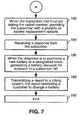
- a subscriber determines when a subscriber has finished dialing a called number.
- the subscriber is provided with a plurality of battery replacement options.
- a response is received from the subscriber.
- a report reminding the customer to change the battery is sent to the billing system.
- the system determines a subscriber email address.
- a replace battery message is sent to the subscriber email address.
- the replace battery message includes a plurality of hypertext link corresponding to a plurality of battery replacement options.
- FIGS. 6 & 7 are a flow chart of the steps used in a remote battery replacement notification method in accordance with one embodiment of the invention.
- the process starts, step 170 , by periodically polling a subscriber unit for a battery state by a communication system at step 172 .
- a response including a battery state is received at step 174 .
- the process starts over.
- the battery state indicates that the battery requires replacing
- a replace battery message is sent to a compact service node at step 178 .
- a response is received from the subscriber at step 184 .
- a battery discount is generated for inclusion in a subscriber bill at step 186 .
- the battery discount is a coupon.
- a report is transmitted to a billing system to remind the customer to change a battery which ends the process at step 190 .
- the methods described herein can be implemented as computer-readable instructions stored on a computer-readable storage medium that when executed by a computer will perform the methods described herein.
Abstract
Description
Claims (15)
Priority Applications (1)
| Application Number | Priority Date | Filing Date | Title |
|---|---|---|---|
| US12/255,298 US8060081B2 (en) | 2000-04-17 | 2008-10-21 | Remote battery replacement notification system and method |
Applications Claiming Priority (3)
| Application Number | Priority Date | Filing Date | Title |
|---|---|---|---|
| US09/550,991 US6775562B1 (en) | 2000-04-17 | 2000-04-17 | Remote battery replacement notification system and method |
| US10/844,222 US7457647B2 (en) | 2000-04-17 | 2004-05-12 | Remote battery replacement notification system and method |
| US12/255,298 US8060081B2 (en) | 2000-04-17 | 2008-10-21 | Remote battery replacement notification system and method |
Related Parent Applications (1)
| Application Number | Title | Priority Date | Filing Date |
|---|---|---|---|
| US10/844,222 Continuation US7457647B2 (en) | 2000-04-17 | 2004-05-12 | Remote battery replacement notification system and method |
Publications (2)
| Publication Number | Publication Date |
|---|---|
| US20090041228A1 US20090041228A1 (en) | 2009-02-12 |
| US8060081B2 true US8060081B2 (en) | 2011-11-15 |
Family
ID=32825578
Family Applications (3)
| Application Number | Title | Priority Date | Filing Date |
|---|---|---|---|
| US09/550,991 Expired - Lifetime US6775562B1 (en) | 2000-04-17 | 2000-04-17 | Remote battery replacement notification system and method |
| US10/844,222 Expired - Fee Related US7457647B2 (en) | 2000-04-17 | 2004-05-12 | Remote battery replacement notification system and method |
| US12/255,298 Expired - Fee Related US8060081B2 (en) | 2000-04-17 | 2008-10-21 | Remote battery replacement notification system and method |
Family Applications Before (2)
| Application Number | Title | Priority Date | Filing Date |
|---|---|---|---|
| US09/550,991 Expired - Lifetime US6775562B1 (en) | 2000-04-17 | 2000-04-17 | Remote battery replacement notification system and method |
| US10/844,222 Expired - Fee Related US7457647B2 (en) | 2000-04-17 | 2004-05-12 | Remote battery replacement notification system and method |
Country Status (1)
| Country | Link |
|---|---|
| US (3) | US6775562B1 (en) |
Cited By (3)
| Publication number | Priority date | Publication date | Assignee | Title |
|---|---|---|---|---|
| US20090167543A1 (en) * | 2007-12-28 | 2009-07-02 | At&T Knowledge Ventures, L.P. | Configurable Battery End-of-Life Indicator |
| US8837940B2 (en) | 2010-04-14 | 2014-09-16 | Adc Telecommunications, Inc. | Methods and systems for distributing fiber optic telecommunication services to local areas and for supporting distributed antenna systems |
| US8929740B2 (en) * | 2009-03-05 | 2015-01-06 | Adc Telecommunications, Inc. | Methods, systems and devices for integrating wireless technology into a fiber optic network |
Families Citing this family (33)
| Publication number | Priority date | Publication date | Assignee | Title |
|---|---|---|---|---|
| US6415150B1 (en) * | 1998-09-11 | 2002-07-02 | Ameritech Corporation | System and method for providing telecommunications service using a wireless link |
| US6775562B1 (en) * | 2000-04-17 | 2004-08-10 | Sbc Properties, Lp | Remote battery replacement notification system and method |
| JP2004128827A (en) * | 2002-10-02 | 2004-04-22 | Hitachi Ltd | Portable electronic apparatus, apparatus and method for supplying power source |
| US20040242286A1 (en) * | 2003-05-28 | 2004-12-02 | Benco David S. | Configurable network initiated response to mobile low battery condition |
| US20050261037A1 (en) * | 2004-05-18 | 2005-11-24 | Raghunath Mandayam T | Conservation of battery power in mobile devices having communication capabilities |
| US20060187071A1 (en) * | 2005-02-11 | 2006-08-24 | Sbc Knowledge Ventures, L.P. | System and method for notification of power system status |
| WO2007092534A2 (en) * | 2006-02-06 | 2007-08-16 | Woods Hole Oceanographic Institution | Communication/power network having out-of-band time and control signaling |
| US20070274716A1 (en) * | 2006-05-11 | 2007-11-29 | Ying Goangshiuan S | Methods and apparatus to provide local warning of a low battery condition from an optical network terminal |
| US8099140B2 (en) * | 2006-11-24 | 2012-01-17 | Semiconductor Energy Laboratory Co., Ltd. | Wireless power supply system and wireless power supply method |
| US20080247760A1 (en) * | 2007-04-09 | 2008-10-09 | At&T Knowledge Ventures, L.P. | System for wireless alarm reporting |
| US9451038B2 (en) * | 2007-10-02 | 2016-09-20 | International Business Machines Corporation | Managing contact status updates in a presence management system |
| US8136125B2 (en) * | 2007-10-02 | 2012-03-13 | International Business Machines Corporation | Prioritization for online contact status updates |
| US7957775B2 (en) * | 2007-11-05 | 2011-06-07 | International Business Machines Corporation | Low battery notification service for wireless device users |
| WO2011056779A2 (en) * | 2009-11-03 | 2011-05-12 | Bravo Zulu International, Ltd. | Automated battery scanning, repair, and optimization |
| US8301432B1 (en) * | 2009-11-05 | 2012-10-30 | Symantec Corporation | Systems and methods for determining a power cycle of a power source of a mobile device |
| US8776145B2 (en) | 2011-09-16 | 2014-07-08 | Elwha Llc | In-transit electronic media with location-based content |
| US9158908B2 (en) | 2011-09-16 | 2015-10-13 | Elwha Llc | Power source for in-transit electronic media |
| US20130290057A1 (en) * | 2012-04-27 | 2013-10-31 | Honeywell International Inc. | System and method of device maintenance reporting via a wireless protocol |
| US9551758B2 (en) | 2012-12-27 | 2017-01-24 | Duracell U.S. Operations, Inc. | Remote sensing of remaining battery capacity using on-battery circuitry |
| US9478850B2 (en) | 2013-05-23 | 2016-10-25 | Duracell U.S. Operations, Inc. | Omni-directional antenna for a cylindrical body |
| US9726763B2 (en) | 2013-06-21 | 2017-08-08 | Duracell U.S. Operations, Inc. | Systems and methods for remotely determining a battery characteristic |
| CN105518953B (en) | 2013-08-09 | 2019-09-10 | 英国电讯有限公司 | For monitoring the electrical equipment and its operating method of battery condition |
| US9882250B2 (en) | 2014-05-30 | 2018-01-30 | Duracell U.S. Operations, Inc. | Indicator circuit decoupled from a ground plane |
| US10297875B2 (en) | 2015-09-01 | 2019-05-21 | Duracell U.S. Operations, Inc. | Battery including an on-cell indicator |
| US10628898B2 (en) * | 2016-03-07 | 2020-04-21 | Husqvarna Ab | Identifying and locating a substitute battery for a construction job site power tool |
| US10540728B2 (en) * | 2016-03-09 | 2020-01-21 | Husqvarna Ab | Locating substitute construction tools within a construction worksite |
| US20170300096A1 (en) * | 2016-04-15 | 2017-10-19 | Tane Martin | Energy storage servicing systems and methods |
| US10483634B2 (en) | 2016-11-01 | 2019-11-19 | Duracell U.S. Operations, Inc. | Positive battery terminal antenna ground plane |
| US10608293B2 (en) | 2016-11-01 | 2020-03-31 | Duracell U.S. Operations, Inc. | Dual sided reusable battery indicator |
| US10818979B2 (en) | 2016-11-01 | 2020-10-27 | Duracell U.S. Operations, Inc. | Single sided reusable battery indicator |
| US11024891B2 (en) | 2016-11-01 | 2021-06-01 | Duracell U.S. Operations, Inc. | Reusable battery indicator with lock and key mechanism |
| US10151802B2 (en) | 2016-11-01 | 2018-12-11 | Duracell U.S. Operations, Inc. | Reusable battery indicator with electrical lock and key |
| US11837754B2 (en) | 2020-12-30 | 2023-12-05 | Duracell U.S. Operations, Inc. | Magnetic battery cell connection mechanism |
Citations (30)
| Publication number | Priority date | Publication date | Assignee | Title |
|---|---|---|---|---|
| US4609864A (en) | 1984-11-13 | 1986-09-02 | Gte Communication Systems Corp. | Analog process controller with digital monitor |
| US5016269A (en) | 1988-11-04 | 1991-05-14 | Gte Mobilnet, Incorporated | Method and apparatus for utilizing a cellular telephone in a programmable, intelligent emergency freeway callbox |
| US5133081A (en) | 1989-11-03 | 1992-07-21 | Mayo Scott T | Remotely controllable message broadcast system including central programming station, remote message transmitters and repeaters |
| USRE34496E (en) | 1985-11-25 | 1994-01-04 | Cellular Communications Corporation | Apparatus and method for a cellular freeway emergency telephone service |
| US5469494A (en) | 1994-03-02 | 1995-11-21 | Telular International, Inc. | Self-diagnostic system for cellular-transceiver systems |
| US5546072A (en) * | 1994-07-22 | 1996-08-13 | Irw Inc. | Alert locator |
| US5568654A (en) | 1993-10-07 | 1996-10-22 | Any Co., Ltd. | Mobile radio telecommunications system |
| US5774791A (en) | 1993-07-02 | 1998-06-30 | Phonic Ear Incorporated | Low power wireless communication system employing magnetic control zones |
| US5859894A (en) | 1994-03-02 | 1999-01-12 | Telular Corporation | Self-diagnostic system for cellular-transceiver systems with remote-reporting capabilities |
| US5889465A (en) | 1995-07-25 | 1999-03-30 | Jersey Central Power & Light Company | Power service unit with automated dialer and other enhancements |
| US5901361A (en) | 1996-12-11 | 1999-05-04 | Telefonaktiebolaget L M Ericsson Publ | Mobile communications apparatus uplink message transmission of battery output level information |
| WO1999048070A1 (en) | 1998-03-17 | 1999-09-23 | Ascot Management Solutions Limited | Monitoring system |
| US5966428A (en) | 1995-07-24 | 1999-10-12 | Telular Corp. | Self diagnostic system for cellular-transceiver systems with remote-reporting capabilities |
| US6028916A (en) | 1997-12-31 | 2000-02-22 | Mediaone Group, Inc. | Method and apparatus for maintaining availability of lifeline telephony service on a hybrid fiber-coax network |
| US6072984A (en) | 1995-10-27 | 2000-06-06 | Location Science Corporation | Apparatus for monitoring cable television system remote equipment performance and status using a cell modem |
| US6150928A (en) | 1996-04-24 | 2000-11-21 | Murray; Steve | Multi passenger frequency controlled alarm system |
| US6236326B1 (en) | 1999-10-29 | 2001-05-22 | Vtech Telecommunications, Ltd. | Method and apparatus for intelligently signaling a battery charge condition in a wireless telephone |
| US6321208B1 (en) | 1995-04-19 | 2001-11-20 | Brightstreet.Com, Inc. | Method and system for electronic distribution of product redemption coupons |
| US6459896B1 (en) * | 1999-10-18 | 2002-10-01 | Gateway, Inc. | Notification of low-battery in a wireless network |
| US6459440B1 (en) * | 1999-07-15 | 2002-10-01 | Motorola, Inc. | Method and apparatus for automatic deletion of a pop-up window |
| US6480727B1 (en) | 1999-01-12 | 2002-11-12 | Tellabs Operations, Inc. | Using inactivity levels to extend subscriber equipment battery life |
| US6545448B1 (en) | 2001-12-18 | 2003-04-08 | Intel Corporation | Detection of the end-of-life for a rechargeable battery |
| US6624635B1 (en) | 1999-10-23 | 2003-09-23 | Cisco Technology, Inc. | Uninterruptable power supply |
| US6650750B1 (en) | 2000-08-18 | 2003-11-18 | Lucent Technologies Inc. | Voice notification for a battery alarm in a network interface unit |
| US6658576B1 (en) * | 1999-09-29 | 2003-12-02 | Smartpower Corporation | Energy-conserving communication apparatus selectively switching between a main processor with main operating instructions and keep-alive processor with keep-alive operating instruction |
| US6775562B1 (en) | 2000-04-17 | 2004-08-10 | Sbc Properties, Lp | Remote battery replacement notification system and method |
| US20040207404A1 (en) | 2003-04-16 | 2004-10-21 | Song Zhang | Power supply, and apparatus and method for operating a power supply |
| US20040213286A1 (en) | 2003-01-03 | 2004-10-28 | Jette Michael H. | Fiber to the home broadband home unit |
| US20060034449A1 (en) | 2004-03-09 | 2006-02-16 | Joerger Richard B | System and method of delivering operating power and power source status signals over a single pair of wires |
| US20060053309A1 (en) | 2004-07-19 | 2006-03-09 | Vereen Jerry D | Optical network terminal with low-power sleep logic that substantially extends the life of the battery after the AC main power supply has been lost |
Family Cites Families (1)
| Publication number | Priority date | Publication date | Assignee | Title |
|---|---|---|---|---|
| JP2000517310A (en) * | 1996-08-27 | 2000-12-26 | セラニーズ・ゲーエムベーハー | Diene telomerization method |
-
2000
- 2000-04-17 US US09/550,991 patent/US6775562B1/en not_active Expired - Lifetime
-
2004
- 2004-05-12 US US10/844,222 patent/US7457647B2/en not_active Expired - Fee Related
-
2008
- 2008-10-21 US US12/255,298 patent/US8060081B2/en not_active Expired - Fee Related
Patent Citations (32)
| Publication number | Priority date | Publication date | Assignee | Title |
|---|---|---|---|---|
| US4609864A (en) | 1984-11-13 | 1986-09-02 | Gte Communication Systems Corp. | Analog process controller with digital monitor |
| USRE34496E (en) | 1985-11-25 | 1994-01-04 | Cellular Communications Corporation | Apparatus and method for a cellular freeway emergency telephone service |
| US5016269A (en) | 1988-11-04 | 1991-05-14 | Gte Mobilnet, Incorporated | Method and apparatus for utilizing a cellular telephone in a programmable, intelligent emergency freeway callbox |
| US5133081A (en) | 1989-11-03 | 1992-07-21 | Mayo Scott T | Remotely controllable message broadcast system including central programming station, remote message transmitters and repeaters |
| US5774791A (en) | 1993-07-02 | 1998-06-30 | Phonic Ear Incorporated | Low power wireless communication system employing magnetic control zones |
| US5568654A (en) | 1993-10-07 | 1996-10-22 | Any Co., Ltd. | Mobile radio telecommunications system |
| US5859894A (en) | 1994-03-02 | 1999-01-12 | Telular Corporation | Self-diagnostic system for cellular-transceiver systems with remote-reporting capabilities |
| US5469494A (en) | 1994-03-02 | 1995-11-21 | Telular International, Inc. | Self-diagnostic system for cellular-transceiver systems |
| US5546072A (en) * | 1994-07-22 | 1996-08-13 | Irw Inc. | Alert locator |
| US6321208B1 (en) | 1995-04-19 | 2001-11-20 | Brightstreet.Com, Inc. | Method and system for electronic distribution of product redemption coupons |
| US5966428A (en) | 1995-07-24 | 1999-10-12 | Telular Corp. | Self diagnostic system for cellular-transceiver systems with remote-reporting capabilities |
| US5889465A (en) | 1995-07-25 | 1999-03-30 | Jersey Central Power & Light Company | Power service unit with automated dialer and other enhancements |
| US6072984A (en) | 1995-10-27 | 2000-06-06 | Location Science Corporation | Apparatus for monitoring cable television system remote equipment performance and status using a cell modem |
| US6150928A (en) | 1996-04-24 | 2000-11-21 | Murray; Steve | Multi passenger frequency controlled alarm system |
| US5901361A (en) | 1996-12-11 | 1999-05-04 | Telefonaktiebolaget L M Ericsson Publ | Mobile communications apparatus uplink message transmission of battery output level information |
| US6028916A (en) | 1997-12-31 | 2000-02-22 | Mediaone Group, Inc. | Method and apparatus for maintaining availability of lifeline telephony service on a hybrid fiber-coax network |
| US6393105B1 (en) | 1997-12-31 | 2002-05-21 | Mediaone Group, Inc. | Method and apparatus for monitoring local telephony service power on a hybrid fiber-coax network |
| WO1999048070A1 (en) | 1998-03-17 | 1999-09-23 | Ascot Management Solutions Limited | Monitoring system |
| US6480727B1 (en) | 1999-01-12 | 2002-11-12 | Tellabs Operations, Inc. | Using inactivity levels to extend subscriber equipment battery life |
| US6459440B1 (en) * | 1999-07-15 | 2002-10-01 | Motorola, Inc. | Method and apparatus for automatic deletion of a pop-up window |
| US6658576B1 (en) * | 1999-09-29 | 2003-12-02 | Smartpower Corporation | Energy-conserving communication apparatus selectively switching between a main processor with main operating instructions and keep-alive processor with keep-alive operating instruction |
| US6459896B1 (en) * | 1999-10-18 | 2002-10-01 | Gateway, Inc. | Notification of low-battery in a wireless network |
| US6624635B1 (en) | 1999-10-23 | 2003-09-23 | Cisco Technology, Inc. | Uninterruptable power supply |
| US6236326B1 (en) | 1999-10-29 | 2001-05-22 | Vtech Telecommunications, Ltd. | Method and apparatus for intelligently signaling a battery charge condition in a wireless telephone |
| US6775562B1 (en) | 2000-04-17 | 2004-08-10 | Sbc Properties, Lp | Remote battery replacement notification system and method |
| US7457647B2 (en) | 2000-04-17 | 2008-11-25 | At&T Intellectual Property I, L.P. | Remote battery replacement notification system and method |
| US6650750B1 (en) | 2000-08-18 | 2003-11-18 | Lucent Technologies Inc. | Voice notification for a battery alarm in a network interface unit |
| US6545448B1 (en) | 2001-12-18 | 2003-04-08 | Intel Corporation | Detection of the end-of-life for a rechargeable battery |
| US20040213286A1 (en) | 2003-01-03 | 2004-10-28 | Jette Michael H. | Fiber to the home broadband home unit |
| US20040207404A1 (en) | 2003-04-16 | 2004-10-21 | Song Zhang | Power supply, and apparatus and method for operating a power supply |
| US20060034449A1 (en) | 2004-03-09 | 2006-02-16 | Joerger Richard B | System and method of delivering operating power and power source status signals over a single pair of wires |
| US20060053309A1 (en) | 2004-07-19 | 2006-03-09 | Vereen Jerry D | Optical network terminal with low-power sleep logic that substantially extends the life of the battery after the AC main power supply has been lost |
Non-Patent Citations (11)
| Title |
|---|
| Notice of Allowance issued by the United States Patent and Trademark Office in connection with U.S. Appl. No. 09/550,991 on Apr. 20, 2004 (5 pages). |
| Notice of Allowance issued by the United States Patent and Trademark Office in connection with U.S. Appl. No. 10/844,222 on Sep. 5, 2008 (6 pages). |
| Office action issued by the United States Patent and Trademark Office in connection with U.S. Appl. No. 09/550,991 on Aug. 21, 2003 (8 pages). |
| Office action issued by the United States Patent and Trademark Office in connection with U.S. Appl. No. 09/550,991 on Dec. 4, 2002 (11 pages). |
| Office action issued by the United States Patent and Trademark Office in connection with U.S. Appl. No. 09/550,991 on Feb. 26, 2003 (9 pages). |
| Office action issued by the United States Patent and Trademark Office in connection with U.S. Appl. No. 09/550,991 on Jan. 2, 2004 (10 pages). |
| Office action issued by the United States Patent and Trademark Office in connection with U.S. Appl. No. 09/550,991 on Jun. 4, 2003 (9 pages). |
| Office action issued by the United States Patent and Trademark Office in connection with U.S. Appl. No. 10/844,222 on Aug. 28, 2006 (12 pages). |
| Office action issued by the United States Patent and Trademark Office in connection with U.S. Appl. No. 10/844,222 on Jun. 1, 2007 (11 pages). |
| Office action issued by the United States Patent and Trademark Office in connection with U.S. Appl. No. 10/844,222 on Jun. 13, 2008 (8 pages). |
| Office action issued by the United States Patent and Trademark Office in connection with U.S. Appl. No. 10/844,222 on Oct. 3, 2007 (10 pages). |
Cited By (12)
| Publication number | Priority date | Publication date | Assignee | Title |
|---|---|---|---|---|
| US20090167543A1 (en) * | 2007-12-28 | 2009-07-02 | At&T Knowledge Ventures, L.P. | Configurable Battery End-of-Life Indicator |
| US9160200B2 (en) | 2007-12-28 | 2015-10-13 | At&T Intellectual Property I, L.P. | Configurable battery end-of-life indicator |
| US8929740B2 (en) * | 2009-03-05 | 2015-01-06 | Adc Telecommunications, Inc. | Methods, systems and devices for integrating wireless technology into a fiber optic network |
| US9438342B2 (en) | 2009-03-05 | 2016-09-06 | Commscope Technologies Llc | Methods, systems, and devices for integrating wireless technology into a fiber optic network |
| US9893813B2 (en) | 2009-03-05 | 2018-02-13 | Commscope Technologies Llc | Methods, systems, and devices for integrating wireless technology into a fiber optic network |
| US10135534B2 (en) | 2009-03-05 | 2018-11-20 | Commscope Technologies Llc | Methods, systems, and devices for integrating wireless technology into a fiber optic network |
| US10630388B2 (en) | 2009-03-05 | 2020-04-21 | Commscope Technologies Llc | Methods, systems, and devices for integrating wireless technology into a fiber optic network |
| US11044014B2 (en) | 2009-03-05 | 2021-06-22 | Commscope Technologies Llc | Methods, systems, and devices for integrating wireless technology into a fiber optic network |
| US11438070B2 (en) | 2009-03-05 | 2022-09-06 | Commscope Technologies Llc | Methods, systems, and devices for integrating wireless technology into a fiber optic network |
| US8837940B2 (en) | 2010-04-14 | 2014-09-16 | Adc Telecommunications, Inc. | Methods and systems for distributing fiber optic telecommunication services to local areas and for supporting distributed antenna systems |
| US9414137B2 (en) | 2010-04-14 | 2016-08-09 | Commscope Technologies Llc | Methods and systems for distributing fiber optic telecommunication services to local areas and for supporting distributed antenna systems |
| US10819444B2 (en) | 2010-04-14 | 2020-10-27 | Commscope Technologies Llc | Methods and systems for distributing fiber optic telecommunication services to local areas and for supporting distributed antenna systems |
Also Published As
| Publication number | Publication date |
|---|---|
| US7457647B2 (en) | 2008-11-25 |
| US20040235534A1 (en) | 2004-11-25 |
| US20090041228A1 (en) | 2009-02-12 |
| US6775562B1 (en) | 2004-08-10 |
Similar Documents
| Publication | Publication Date | Title |
|---|---|---|
| US8060081B2 (en) | Remote battery replacement notification system and method | |
| US6509833B2 (en) | Method and system for providing a warning alert | |
| US6373933B1 (en) | Method for implementing transaction-based billing for telephone services | |
| US8963367B2 (en) | Technique for remote power feeding in access networks | |
| US5930702A (en) | Personal mobility communication system | |
| US5982854A (en) | Fiber optic based subscriber terminal | |
| EP2286578B1 (en) | Power backup system | |
| US20030050837A1 (en) | Method and system providing advertisement using tone of ringing sounds of mobile phone and commerical transaction service in association with the same | |
| US20080195881A1 (en) | Method and apparatus for providing on-demand backup power for an optical network terminal | |
| US20060187071A1 (en) | System and method for notification of power system status | |
| JPH08130579A (en) | Communication network having communication service function with advertisement | |
| US6546094B1 (en) | Provisioning of cable telephone service | |
| US6151388A (en) | Communication charge management system | |
| KR20000058949A (en) | Advertising method and commerce model using the paging time of mobile phone | |
| KR100627646B1 (en) | Method, system and terminal for providing customized information during call setup process in telecommunication systems | |
| KR20010064727A (en) | Method for servicing advertisement for call charges in wireless communication system | |
| KR100404890B1 (en) | method and apparatus for providing advertisement during call wait in telephone network system and communication terminal | |
| KR19980072331A (en) | Selective wireless calling device for advertising | |
| KR100489816B1 (en) | Method for billing in audio response system | |
| GB2347048A (en) | Notification of message receipt using CLI | |
| KR20000024300A (en) | Advertisement Service Method with Reduction of Call Charge | |
| KR20050105753A (en) | Method, system for providing customized information during call setup process in telecommunication systems, and terminal for the same | |
| JP2005159435A (en) | Terminal information management apparatus, terminal apparatus, electronic apparatus-mounting terminal information notice system, and electronic apparatus-mounting terminal information notice method | |
| CN101674190A (en) | Message sending method, message sending device and management system of terminal device | |
| CN101820476A (en) | System and method for monitoring message usage |
Legal Events
| Date | Code | Title | Description |
|---|---|---|---|
| FEPP | Fee payment procedure |
Free format text: PAYOR NUMBER ASSIGNED (ORIGINAL EVENT CODE: ASPN); ENTITY STATUS OF PATENT OWNER: LARGE ENTITY |
|
| ZAAA | Notice of allowance and fees due |
Free format text: ORIGINAL CODE: NOA |
|
| ZAAB | Notice of allowance mailed |
Free format text: ORIGINAL CODE: MN/=. |
|
| STCF | Information on status: patent grant |
Free format text: PATENTED CASE |
|
| FPAY | Fee payment |
Year of fee payment: 4 |
|
| MAFP | Maintenance fee payment |
Free format text: PAYMENT OF MAINTENANCE FEE, 8TH YEAR, LARGE ENTITY (ORIGINAL EVENT CODE: M1552); ENTITY STATUS OF PATENT OWNER: LARGE ENTITY Year of fee payment: 8 |
|
| FEPP | Fee payment procedure |
Free format text: MAINTENANCE FEE REMINDER MAILED (ORIGINAL EVENT CODE: REM.); ENTITY STATUS OF PATENT OWNER: LARGE ENTITY |
|
| LAPS | Lapse for failure to pay maintenance fees |
Free format text: PATENT EXPIRED FOR FAILURE TO PAY MAINTENANCE FEES (ORIGINAL EVENT CODE: EXP.); ENTITY STATUS OF PATENT OWNER: LARGE ENTITY |
|
| STCH | Information on status: patent discontinuation |
Free format text: PATENT EXPIRED DUE TO NONPAYMENT OF MAINTENANCE FEES UNDER 37 CFR 1.362 |
|
| FP | Lapsed due to failure to pay maintenance fee |
Effective date: 20231115 |