US8061586B2 - Comestible product dispensers and methods of making and using same - Google Patents
Comestible product dispensers and methods of making and using same Download PDFInfo
- Publication number
- US8061586B2 US8061586B2 US11/609,455 US60945506A US8061586B2 US 8061586 B2 US8061586 B2 US 8061586B2 US 60945506 A US60945506 A US 60945506A US 8061586 B2 US8061586 B2 US 8061586B2
- Authority
- US
- United States
- Prior art keywords
- slot
- package
- slot portion
- wall
- flap
- Prior art date
- Legal status (The legal status is an assumption and is not a legal conclusion. Google has not performed a legal analysis and makes no representation as to the accuracy of the status listed.)
- Active, expires
Links
- 238000000034 method Methods 0.000 title description 22
- 229920003023 plastic Polymers 0.000 description 29
- 239000004033 plastic Substances 0.000 description 29
- 239000003292 glue Substances 0.000 description 26
- 239000000123 paper Substances 0.000 description 18
- 230000008901 benefit Effects 0.000 description 17
- 239000000853 adhesive Substances 0.000 description 15
- 230000001070 adhesive effect Effects 0.000 description 15
- 238000004806 packaging method and process Methods 0.000 description 15
- 239000011087 paperboard Substances 0.000 description 15
- 239000000463 material Substances 0.000 description 14
- 239000000758 substrate Substances 0.000 description 11
- 239000011888 foil Substances 0.000 description 9
- 230000033001 locomotion Effects 0.000 description 8
- 239000004831 Hot glue Substances 0.000 description 7
- 238000002347 injection Methods 0.000 description 7
- 239000007924 injection Substances 0.000 description 7
- 229920000298 Cellophane Polymers 0.000 description 6
- 230000013011 mating Effects 0.000 description 6
- 229920000642 polymer Polymers 0.000 description 5
- 125000006850 spacer group Chemical group 0.000 description 5
- 238000004519 manufacturing process Methods 0.000 description 4
- 230000002093 peripheral effect Effects 0.000 description 4
- NOOLISFMXDJSKH-KXUCPTDWSA-N (-)-Menthol Chemical compound CC(C)[C@@H]1CC[C@@H](C)C[C@H]1O NOOLISFMXDJSKH-KXUCPTDWSA-N 0.000 description 3
- 210000001015 abdomen Anatomy 0.000 description 3
- 239000011111 cardboard Substances 0.000 description 3
- 239000004615 ingredient Substances 0.000 description 3
- 238000012986 modification Methods 0.000 description 3
- 230000004048 modification Effects 0.000 description 3
- 235000016709 nutrition Nutrition 0.000 description 3
- 239000002131 composite material Substances 0.000 description 2
- 239000000796 flavoring agent Substances 0.000 description 2
- 235000019634 flavors Nutrition 0.000 description 2
- 239000012943 hotmelt Substances 0.000 description 2
- 238000003780 insertion Methods 0.000 description 2
- 230000037431 insertion Effects 0.000 description 2
- 238000003825 pressing Methods 0.000 description 2
- 241000167854 Bourreria succulenta Species 0.000 description 1
- 244000223760 Cinnamomum zeylanicum Species 0.000 description 1
- NOOLISFMXDJSKH-UHFFFAOYSA-N DL-menthol Natural products CC(C)C1CCC(C)CC1O NOOLISFMXDJSKH-UHFFFAOYSA-N 0.000 description 1
- 235000009754 Vitis X bourquina Nutrition 0.000 description 1
- 235000012333 Vitis X labruscana Nutrition 0.000 description 1
- 240000006365 Vitis vinifera Species 0.000 description 1
- 235000014787 Vitis vinifera Nutrition 0.000 description 1
- 230000001154 acute effect Effects 0.000 description 1
- 238000004026 adhesive bonding Methods 0.000 description 1
- 239000012080 ambient air Substances 0.000 description 1
- 230000004888 barrier function Effects 0.000 description 1
- 238000005452 bending Methods 0.000 description 1
- 230000015556 catabolic process Effects 0.000 description 1
- 235000019693 cherries Nutrition 0.000 description 1
- 235000017803 cinnamon Nutrition 0.000 description 1
- 238000005336 cracking Methods 0.000 description 1
- 238000006731 degradation reaction Methods 0.000 description 1
- 230000000593 degrading effect Effects 0.000 description 1
- 230000003467 diminishing effect Effects 0.000 description 1
- 230000000694 effects Effects 0.000 description 1
- 238000004049 embossing Methods 0.000 description 1
- 239000012530 fluid Substances 0.000 description 1
- 238000002372 labelling Methods 0.000 description 1
- 230000007246 mechanism Effects 0.000 description 1
- 229940041616 menthol Drugs 0.000 description 1
- 230000035764 nutrition Effects 0.000 description 1
- 230000008520 organization Effects 0.000 description 1
- 238000012856 packing Methods 0.000 description 1
- 230000000149 penetrating effect Effects 0.000 description 1
- 230000009467 reduction Effects 0.000 description 1
- IHQKEDIOMGYHEB-UHFFFAOYSA-M sodium dimethylarsinate Chemical class [Na+].C[As](C)([O-])=O IHQKEDIOMGYHEB-UHFFFAOYSA-M 0.000 description 1
- 239000007787 solid Substances 0.000 description 1
- 238000003860 storage Methods 0.000 description 1
Images


Classifications
-
- B—PERFORMING OPERATIONS; TRANSPORTING
- B65—CONVEYING; PACKING; STORING; HANDLING THIN OR FILAMENTARY MATERIAL
- B65D—CONTAINERS FOR STORAGE OR TRANSPORT OF ARTICLES OR MATERIALS, e.g. BAGS, BARRELS, BOTTLES, BOXES, CANS, CARTONS, CRATES, DRUMS, JARS, TANKS, HOPPERS, FORWARDING CONTAINERS; ACCESSORIES, CLOSURES, OR FITTINGS THEREFOR; PACKAGING ELEMENTS; PACKAGES
- B65D5/00—Rigid or semi-rigid containers of polygonal cross-section, e.g. boxes, cartons or trays, formed by folding or erecting one or more blanks made of paper
- B65D5/02—Rigid or semi-rigid containers of polygonal cross-section, e.g. boxes, cartons or trays, formed by folding or erecting one or more blanks made of paper by folding or erecting a single blank to form a tubular body with or without subsequent folding operations, or the addition of separate elements, to close the ends of the body
- B65D5/0254—Rigid or semi-rigid containers of polygonal cross-section, e.g. boxes, cartons or trays, formed by folding or erecting one or more blanks made of paper by folding or erecting a single blank to form a tubular body with or without subsequent folding operations, or the addition of separate elements, to close the ends of the body with end closures formed by inward folding of flaps and securing them by means of a tongue integral with one of the flaps
-
- B—PERFORMING OPERATIONS; TRANSPORTING
- B65—CONVEYING; PACKING; STORING; HANDLING THIN OR FILAMENTARY MATERIAL
- B65D—CONTAINERS FOR STORAGE OR TRANSPORT OF ARTICLES OR MATERIALS, e.g. BAGS, BARRELS, BOTTLES, BOXES, CANS, CARTONS, CRATES, DRUMS, JARS, TANKS, HOPPERS, FORWARDING CONTAINERS; ACCESSORIES, CLOSURES, OR FITTINGS THEREFOR; PACKAGING ELEMENTS; PACKAGES
- B65D5/00—Rigid or semi-rigid containers of polygonal cross-section, e.g. boxes, cartons or trays, formed by folding or erecting one or more blanks made of paper
- B65D5/02—Rigid or semi-rigid containers of polygonal cross-section, e.g. boxes, cartons or trays, formed by folding or erecting one or more blanks made of paper by folding or erecting a single blank to form a tubular body with or without subsequent folding operations, or the addition of separate elements, to close the ends of the body
- B65D5/10—Rigid or semi-rigid containers of polygonal cross-section, e.g. boxes, cartons or trays, formed by folding or erecting one or more blanks made of paper by folding or erecting a single blank to form a tubular body with or without subsequent folding operations, or the addition of separate elements, to close the ends of the body with end closures formed by inward-folding of self-locking flaps hinged to tubular body
-
- B—PERFORMING OPERATIONS; TRANSPORTING
- B65—CONVEYING; PACKING; STORING; HANDLING THIN OR FILAMENTARY MATERIAL
- B65D—CONTAINERS FOR STORAGE OR TRANSPORT OF ARTICLES OR MATERIALS, e.g. BAGS, BARRELS, BOTTLES, BOXES, CANS, CARTONS, CRATES, DRUMS, JARS, TANKS, HOPPERS, FORWARDING CONTAINERS; ACCESSORIES, CLOSURES, OR FITTINGS THEREFOR; PACKAGING ELEMENTS; PACKAGES
- B65D5/00—Rigid or semi-rigid containers of polygonal cross-section, e.g. boxes, cartons or trays, formed by folding or erecting one or more blanks made of paper
- B65D5/38—Drawer-and-shell type containers
-
- B—PERFORMING OPERATIONS; TRANSPORTING
- B65—CONVEYING; PACKING; STORING; HANDLING THIN OR FILAMENTARY MATERIAL
- B65D—CONTAINERS FOR STORAGE OR TRANSPORT OF ARTICLES OR MATERIALS, e.g. BAGS, BARRELS, BOTTLES, BOXES, CANS, CARTONS, CRATES, DRUMS, JARS, TANKS, HOPPERS, FORWARDING CONTAINERS; ACCESSORIES, CLOSURES, OR FITTINGS THEREFOR; PACKAGING ELEMENTS; PACKAGES
- B65D5/00—Rigid or semi-rigid containers of polygonal cross-section, e.g. boxes, cartons or trays, formed by folding or erecting one or more blanks made of paper
- B65D5/42—Details of containers or of foldable or erectable container blanks
- B65D5/44—Integral, inserted or attached portions forming internal or external fittings
- B65D5/52—External stands or display elements for contents
- B65D5/5253—Containers initially closed but folded about a central axis to display the contents in two or more cells
-
- B—PERFORMING OPERATIONS; TRANSPORTING
- B65—CONVEYING; PACKING; STORING; HANDLING THIN OR FILAMENTARY MATERIAL
- B65D—CONTAINERS FOR STORAGE OR TRANSPORT OF ARTICLES OR MATERIALS, e.g. BAGS, BARRELS, BOTTLES, BOXES, CANS, CARTONS, CRATES, DRUMS, JARS, TANKS, HOPPERS, FORWARDING CONTAINERS; ACCESSORIES, CLOSURES, OR FITTINGS THEREFOR; PACKAGING ELEMENTS; PACKAGES
- B65D5/00—Rigid or semi-rigid containers of polygonal cross-section, e.g. boxes, cartons or trays, formed by folding or erecting one or more blanks made of paper
- B65D5/42—Details of containers or of foldable or erectable container blanks
- B65D5/64—Lids
- B65D5/66—Hinged lids
- B65D5/6626—Hinged lids formed by folding extensions of a side panel of a container body formed by erecting a "cross-like" blank
- B65D5/665—Hinged lids formed by folding extensions of a side panel of a container body formed by erecting a "cross-like" blank the lid being held in closed position by self-locking integral flaps or tabs
-
- B—PERFORMING OPERATIONS; TRANSPORTING
- B65—CONVEYING; PACKING; STORING; HANDLING THIN OR FILAMENTARY MATERIAL
- B65D—CONTAINERS FOR STORAGE OR TRANSPORT OF ARTICLES OR MATERIALS, e.g. BAGS, BARRELS, BOTTLES, BOXES, CANS, CARTONS, CRATES, DRUMS, JARS, TANKS, HOPPERS, FORWARDING CONTAINERS; ACCESSORIES, CLOSURES, OR FITTINGS THEREFOR; PACKAGING ELEMENTS; PACKAGES
- B65D5/00—Rigid or semi-rigid containers of polygonal cross-section, e.g. boxes, cartons or trays, formed by folding or erecting one or more blanks made of paper
- B65D5/42—Details of containers or of foldable or erectable container blanks
- B65D5/72—Contents-dispensing means
- B65D5/721—Contents-dispensing means consisting of mobile elements forming part of the containers or attached to the containers
- B65D5/722—Contents-dispensing means consisting of mobile elements forming part of the containers or attached to the containers having an alternating movement co-operating with incised or scored openings near the bottom-edges of the bodies of tubular containers
-
- B—PERFORMING OPERATIONS; TRANSPORTING
- B65—CONVEYING; PACKING; STORING; HANDLING THIN OR FILAMENTARY MATERIAL
- B65D—CONTAINERS FOR STORAGE OR TRANSPORT OF ARTICLES OR MATERIALS, e.g. BAGS, BARRELS, BOTTLES, BOXES, CANS, CARTONS, CRATES, DRUMS, JARS, TANKS, HOPPERS, FORWARDING CONTAINERS; ACCESSORIES, CLOSURES, OR FITTINGS THEREFOR; PACKAGING ELEMENTS; PACKAGES
- B65D75/00—Packages comprising articles or materials partially or wholly enclosed in strips, sheets, blanks, tubes, or webs of flexible sheet material, e.g. in folded wrappers
- B65D75/04—Articles or materials wholly enclosed in single sheets or wrapper blanks
- B65D75/20—Articles or materials wholly enclosed in single sheets or wrapper blanks in sheets or blanks doubled around contents and having their opposed free margins united, e.g. by pressure-sensitive adhesive, crimping, heat-sealing, or welding
- B65D75/22—Articles or materials wholly enclosed in single sheets or wrapper blanks in sheets or blanks doubled around contents and having their opposed free margins united, e.g. by pressure-sensitive adhesive, crimping, heat-sealing, or welding the sheet or blank being recessed to accommodate contents
- B65D75/24—Articles or materials wholly enclosed in single sheets or wrapper blanks in sheets or blanks doubled around contents and having their opposed free margins united, e.g. by pressure-sensitive adhesive, crimping, heat-sealing, or welding the sheet or blank being recessed to accommodate contents and formed with several recesses to accommodate a series of articles or quantities of material
- B65D75/245—Articles or materials wholly enclosed in single sheets or wrapper blanks in sheets or blanks doubled around contents and having their opposed free margins united, e.g. by pressure-sensitive adhesive, crimping, heat-sealing, or welding the sheet or blank being recessed to accommodate contents and formed with several recesses to accommodate a series of articles or quantities of material the sheet or blank comprising more than one fold line
-
- B—PERFORMING OPERATIONS; TRANSPORTING
- B65—CONVEYING; PACKING; STORING; HANDLING THIN OR FILAMENTARY MATERIAL
- B65D—CONTAINERS FOR STORAGE OR TRANSPORT OF ARTICLES OR MATERIALS, e.g. BAGS, BARRELS, BOTTLES, BOXES, CANS, CARTONS, CRATES, DRUMS, JARS, TANKS, HOPPERS, FORWARDING CONTAINERS; ACCESSORIES, CLOSURES, OR FITTINGS THEREFOR; PACKAGING ELEMENTS; PACKAGES
- B65D77/00—Packages formed by enclosing articles or materials in preformed containers, e.g. boxes, cartons, sacks or bags
- B65D77/02—Wrapped articles enclosed in rigid or semi-rigid containers
-
- B—PERFORMING OPERATIONS; TRANSPORTING
- B65—CONVEYING; PACKING; STORING; HANDLING THIN OR FILAMENTARY MATERIAL
- B65D—CONTAINERS FOR STORAGE OR TRANSPORT OF ARTICLES OR MATERIALS, e.g. BAGS, BARRELS, BOTTLES, BOXES, CANS, CARTONS, CRATES, DRUMS, JARS, TANKS, HOPPERS, FORWARDING CONTAINERS; ACCESSORIES, CLOSURES, OR FITTINGS THEREFOR; PACKAGING ELEMENTS; PACKAGES
- B65D2313/00—Connecting or fastening means
- B65D2313/10—Adhesive or cohesive means for holding the contents attached to the container
-
- B—PERFORMING OPERATIONS; TRANSPORTING
- B65—CONVEYING; PACKING; STORING; HANDLING THIN OR FILAMENTARY MATERIAL
- B65D—CONTAINERS FOR STORAGE OR TRANSPORT OF ARTICLES OR MATERIALS, e.g. BAGS, BARRELS, BOTTLES, BOXES, CANS, CARTONS, CRATES, DRUMS, JARS, TANKS, HOPPERS, FORWARDING CONTAINERS; ACCESSORIES, CLOSURES, OR FITTINGS THEREFOR; PACKAGING ELEMENTS; PACKAGES
- B65D85/00—Containers, packaging elements or packages, specially adapted for particular articles or materials
- B65D85/60—Containers, packaging elements or packages, specially adapted for particular articles or materials for sweets or like confectionery products
Definitions
- the present invention relates generally to packaging. More particularly, the present invention relates to packaging for storing and dispensing comestible products.
- the packaging for comestible products is very important to the look, marketing and storage of the product. Very often, in addition to text on the packaging, the packaging also attempts to visually convey a message about the type of product, the taste of the product or the purpose of the product. For example, packages for cinnamon or cherry tasting products are often red, packages for grape tasting products are often purple, etc. Once the consumer has identified a desired brand, the consumer can typically choose a product based solely on the color of the packaging.
- packaging can convey other information besides taste whereby the consumer can thereby associate the product with its effect by simply viewing the packaging.
- a comestible product package it is desirable for a comestible product package to be flexible so that it may be sized to hold different desired amounts of product.
- the present invention provides an improved package for comestible products.
- the package includes a plurality of walls defining a package interior and a flexible slot on one of the walls.
- the slot is flexible to permit insertion of a flap into the slot to enclose a package interior.
- the package encourages a two-directional closing motion to prevent accidental opening of the package.
- the comestible product package also maintains the comestible products secured and locked within the package interior.
- the present invention also provides improved product holding and dispensing apparatuses and improved methods for manufacturing, holding and storing products, especially comestible products.
- the packages or dispensers are made of, e.g., paper, paperboard, plastic, or combinations thereof as desired.
- the packages or dispensers disclosed herein are generally wider and thinner than known comestible product packages, making the packages or dispensers of the present invention more user friendly and more easily stored, for example, in a consumer's pants or shirt pockets.
- the products stored in the packages disclosed herein are more freely exposed than in known comestible product packages, so that the consumer can grab products from multiple areas of the package. Even so, the embodiments described below are generally able to hold the products firmly in place so that the consumer can handle and transport the package without fear of dropping or losing products.
- packages that are resealable or recloseable.
- the packages are made of plastic and snap fit or press fit together in a closed position after use. When closed, the plastic packages tend to prevent ambient air from entering the packages.
- Other dispensers are provided that are made of paper or paperboard, which are recloseable, robust and tend not to degrade over multiple uses.
- the packages described herein are also flexible and capable of being configured to house different quantities of comestible sticks, so that a line of products can be consistent between, for example, a five-stick pack and a fifteen-stick pack of comestible products.
- each embodiment may include an outer wrapping or other type of tamper evident device so that a consumer can view readily whether or not someone has tampered with the package or the products stored therein.
- a package having a first wall and a second wall which define a package interior.
- the first wall includes a slot that defines a first slot portion and a second slot portion.
- the first wall also includes a cut-out area extending across both the first and second slot portions.
- the second wall includes a movable flap which is inserted into the slot to enclose the package interior. The cut-out area is so constructed and arranged to allow the flap to move between the first and second slot portions.
- the first slot portion and the second slot portion define a shape such as a circle, an ellipse, an ovoid or egg shape, or a polygon.
- the cut-out area has a shape selected from the group consisting of a lens, an ellipse, a circle, and a polygon.
- the first slot portion is embossed to place the first slot portion above the second slot portion.
- the second slot portion is debossed to place the second slot portion below the first slot portion.
- the second slot portion includes a slit.
- the slit permits the second slot portion to extend away from the first slot portion.
- the slot includes a slot end.
- the slot end may include a lip that permits the second slot portion to extend away from the first slot portion.
- the gap has a width between about 2 to about 8 millimeters.
- the package includes a first wall and a second wall which define a package interior.
- the first wall includes a slot and a cut-out area.
- the slot includes a lip.
- the second wall includes a protruding member which is inserted into the slot.
- the protruding member has a locking edge engaging the lip to secure the protruding member in the slot.
- the locking edge defines a notch.
- the notch cooperatively engages the lip.
- the slot defines a first slot portion and a second slot portion.
- the second slot portion includes a slit which permits the second slot portion to extend away from the first slot portion.
- the cut-out area extends across the first and second slot portions.
- the first slot portion is embossed to place the first slot portion above the second slot portion.
- the second slot portion is debossed to place the second slot portion below the first slot portion.
- a method for closing a package includes providing a package comprising a first wall, a second wall and opposing sidewalls, all of which define a package interior.
- the first wall includes an offset slot and the second wall includes both a moveable flap and a protruding member.
- the method also includes: (i) moving the flap in a first direction to cover at least a portion of the package interior, (ii) inserting the protruding member into the slot in a second direction, the second direction being different from the first direction, and (iii) enclosing the package interior.
- the second direction is selected from the group consisting of a horizontal direction, an angular direction, an arcuate direction, and combinations thereof.
- the slot defines a first slot portion and a second slot portion.
- the method further includes: (a) providing a cut-out area extending across the first and second slot portions, (b) maneuvering the protruding member through the cut-out area, and (c) inserting the protruding member into the slot.
- the method also includes forming a gap between the first slot portion and the second slot portion and inserting the protruding member into the gap.
- the method also includes providing in the second slot portion a slit and utilizing the slit to extend the second slot portion away from the first slot portion.
- the method also includes providing the protruding member with a locking edge, an end of the slot with a lip, and engaging the locking edge with the lip to enclose the package interior.
- a comestible product dispenser in a further embodiment, includes (i) a multi-sided housing with an open side, the open side bounded by multiple edges; (ii) a product compartment hingedly attached to one of the edges; and (iii) wherein the compartment includes a catch and at least one of the sides includes a stop, the stop located to abut the catch when the compartment is rotated about the hinge to a desired product dispensing location.
- the compartment is sized to hold a stack or stacks of comestible product sticks.
- the dispenser is folded together from a single piece.
- the dispenser is made of a material selected from the group consisting of: paper, paperboard, plastic, a polymer and any combination thereof.
- the compartment includes a front wall that is substantially the shape of the open side.
- the compartment includes at least one side wall connected to the front wall, at least one of the front wall and the side wall defining an opening that aids a consumer in removing products from the compartment.
- the compartment and the housing employ a tongue and slot arrangement to aid in holding the compartment in a closed position with respect to the housing when desired.
- the slot arrangement is multi-segmented.
- the tongue and slot arrangement includes notches to prevent tearing of the tongue.
- the compartment in a closed position is disposed inside the housing.
- the dispenser includes an outer wrapper and a tear strip.
- a comestible product dispenser in another embodiment, includes (i) a top portion including a top wall and side walls; (ii) a base portion hingedly attached to the top portion; and (iii) a plurality of comestible products releasably attached along a side of the products to the base portion so that when the top portion is rotated away from the base multiple sides of at least some of the products are exposed.
- the products are attached in a row to the base.
- the products are each wrapped individually in a wrapping.
- the products are adhered to the base.
- the adhesion is caused using hot glue, cold glue or both.
- the base includes at least one glue strip and the products are adhered to the glue strip.
- the dispenser is folded together from a single piece.
- the comestible products are releasably attached to the base portion so that when the top portion is rotated away from the base three sides of at least some of the products are exposed.
- the dispenser includes an outer wrapper and a tear strip.
- a comestible product dispenser in a further embodiment, includes (i) a top portion including a top wall and side walls; (ii) a bottom portion hingedly attached to the top portion; and (iii) wherein the top portion and the bottom portion include mating press-fitted sides that hold the top portion and the bottom portion together when it is desired, at least one of the top portion and the bottom portion including press-fitting structures spaced apart so that at least one comestible product can be press-fitted by the structures.
- each of the top and bottom portions includes the press-fitting structures, the structures cooperating to form a pair.
- At least one of the top and bottom portions includes multiple press-fitting structures spaced apart so that at least one comestible product can be press-fitted in multiple locations on the portion.
- each of the top and bottom portions includes press-fitting structures, the structures sized to collectively hold a desired amount of the products.
- the press-fitting structures of the top portion are sized to hold a different quantity of products than are the press-fitting structures of the bottom portion.
- only one of the top and bottom portions includes the press-fitting structures.
- At least one of the top portion and bottom portions includes access apertures that aid a consumer in removing one of the products press-fitted therein.
- At least one of the top portion and bottom portions includes access apertures in multiple orientations that aid a consumer in removing one of the products press-fitted therein.
- the top and bottom portions include mating press-fitting perimeters enabling the portions to be press-fitted together completely around the products.
- a comestible product dispenser in yet another embodiment, includes (a) a first portion connected hingedly to a second portion; and (b) wherein the first and second portions are mated on a shared front side along a profile that varies to (i) hold comestible products within each of the portions and (ii) provide a consumer access to the products.
- the profile is a sinusoidal profile.
- the dispenser is made of a material selected from the group consisting of: paper, paperboard, plastic, a polymer and any combination thereof.
- the dispenser includes a flap hingedly attached to one of the first and second portions, the flap covering the shared front side to help prevent products from being removed inadvertently from the portions.
- the first portion holds a different number products than the second portion.
- the products are adhesively secured in at least one of the first and second portions.
- the profile includes snap-fitting apparatus that releasably mates the portions when the portions are closed.
- the profile is perforated initially, and wherein the consumer breaks the perforations to gain access to the products.
- the profile is perforated along multiple walls of each of the first and second portions.
- a comestible product dispenser includes (i) a tray holding at least three stacks of comestible products; and (ii) a sleeve slidingly engaging the tray, the sleeve open on two ends and defining an aperture sized so that a consumer can reach through the aperture of the sleeve to the tray and move the tray relative to the sleeve to extend at least one middle stack past one of the open ends of the sleeve.
- the dispenser is made of a material selected from the group consisting of: paper, paperboard, plastic, a polymer and any combination thereof.
- the stacks include individual wrappers holding the products, the wrappers banded together so that the product is removed from the wrapper while the wrapper remains banded.
- a band banding the wrappers is adhered to the tray.
- the stacks include individual wrappers holding the products, the wrappers adhered together so that the product is removed from the wrapper while the wrappers remain adhered together.
- the dispenser includes an outer wrapper and a tear strip.
- the dispenser or package includes a front wall having a slot, a rear wall, a bottom wall, and opposing sidewalls.
- the walls define a package interior and the rear wall includes a movable flap extending therefrom.
- the flap includes a protruding portion adapted to engage the slot on the front wall and enclose the package interior.
- the package may include a debossed area and an embossed area adjacent to and surrounding the slot on the front wall.
- the package may also include notches adjacent to the slot and or the flap.
- the present invention provides a method for packaging a comestible product.
- the method includes providing a substrate having a plurality of integral panels and folding the panels to form a package having a front wall with a slot, a rear wall having a moveable flap, the flap having a protruding member, a bottom wall and opposing side walls to define a package interior.
- the method further includes engaging the protruding member with the slot to enclose the package interior.
- the protruding member may be disengaged from the slot in order to open the package and remove product from the container interior.
- FIGS. 1 to 6 illustrate multiple different views of one embodiment of a comestible product dispenser and package of the present invention.
- FIGS. 7 to 11 illustrate multiple different views of another embodiment of the comestible product package and dispenser of the present invention.
- FIGS. 12 to 22 illustrate multiple views of a further embodiment of the comestible product package and dispenser of the present invention, wherein FIG. 20 is a section view taken along line XX-XX of FIG. 19 , and FIG. 22 is a section view of FIG. 21 taken along line XXII-XXII of FIG. 21 .
- FIGS. 23 and 24 illustrate still a further different embodiment of the comestible product dispenser and package of the present invention.
- FIGS. 25 to 37 illustrate multiple views of yet another embodiment of the package and dispenser of the present invention, wherein FIG. 31 is a section view taken along line XXXI-XXXI of FIG. 30 , FIG. 32 is a section view taken along the line XXXII-XXXII of FIG. 30 , FIG. 35 is a section view taken along lines XXXV-XXXV of FIG. 34 and FIG. 36 is a sectioned view taken along lines XXXVI-XXXVI of FIG. 34 .
- FIGS. 38 and 39 illustrate multiple views of yet a further embodiment of the package and dispenser of the present invention.
- FIGS. 40 to 46 illustrate different views of still another embodiment of the package and dispenser of the present invention.
- FIG. 47 is a perspective view of another embodiment of a package in accordance with the present invention.
- FIG. 48 is a perspective view of the package of FIG. 47 in an open position.
- FIG. 49 is a plan view of a substrate that may be used to make the package of FIG. 47 .
- FIG. 50 is a perspective view of another embodiment of a package in accordance with the present invention.
- FIG. 51 is a perspective view of the package of FIG. 50 in an open position.
- FIG. 52 is a plan view of a substrate that may be used to make the package of FIG. 50 .
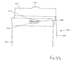
- FIG. 53 is a partial perspective view of another embodiment of a package in accordance with the present invention.
- FIG. 54 is a plan view of a substrate that may be used to make another embodiment of the package.
- FIG. 55 is a front perspective view of the package of FIG. 54 in an open position.
- FIG. 56-58 are front perspective views of the package of FIG. 54 between an open and a closed position.
- FIG. 59 is a cross-sectional view taken along line 59 - 59 of FIG. 58 .
- FIG. 60 is a front perspective view of the package of FIG. 54 in a closed position.
- FIG. 61 is a cross-sectional view taken along line 61 - 61 of FIG. 60 .
- the present invention includes multiple embodiments for a comestible product package and dispenser.
- the comestible products are illustrated as sticks of products, such as flat, rectangular pieces of comestible product.
- the products discussed herein can have any suitable types of shapes, such as a block shape, a pillow shape, a round shape, an oval shape, a rectangular shape, a triangular shape and any combination of same.
- Dispenser 10 includes two main sections, namely, a housing 12 and a compartment 14 connected to housing 12 .
- FIGS. 1 and 2 show compartment 14 in an open position.
- FIGS. 3 to 5 illustrate compartment 14 in a closed position with respect to housing 12 .
- Housing 12 in the illustrated embodiment is generally a five-sided structure having a top wall 16 , sidewalls 18 and 20 , a back wall 22 (referring collectively to back wall portions 22 a and 22 b ) and a bottom wall 24 (referring collectively to bottom wall portions 24 a and 24 b ).
- Hinged compartment 14 includes a front wall 26 and sidewalls 28 and 30 .
- Front wall 26 of compartment 14 and top wall 16 of housing 12 include cooperating apparatus in one embodiment to help hold compartment 14 in a closed position when desired.
- Optional apparatus 58 a and 58 c shown in phantom in FIG. 6 provides one example.
- a tongue 58 a extends from front wall 26 and folds over top wall 16 along fold line 58 b .
- Tongue 58 a is inserted into slot 58 c defined by top wall 16 , creating a friction fit.
- the tongue extends from top wall 16 and front wall 26 defines the slot.
- tongue 58 a and top wall 16 are configured to releasably adhere to one another.
- FIG. 6 illustrates package or dispenser 10 in the flat.
- FIG. 6 shows one embodiment where compartment 14 is formed integrally with housing 12 . Compartment 14 is attached hingedly to housing 12 at hingeline 32 . In an alternative embodiment, compartment 14 is formed as a piece separate from housing 12 and is glued or otherwise attached to housing 12 at bottom portion 24 a.
- the single-piece package or dispenser 10 is glued or otherwise mated together at bottom portions 24 a and 24 b via adhesive or glue 34 .
- Glue or adhesive 34 shown in solid on bottom portion 24 a is received on the side of portion 24 a facing out of the page in FIG. 6 .
- Glue spot 34 shown in phantom line on bottom portion 24 b is placed on the underside of that portion.
- Portion 24 a is folded under and glued to the underside of portion 24 b to form bottom wall 24 . That convention is used throughout this specification.
- back portions 22 a and 22 b are glued or otherwise fixedly mated together to form back wall 22 .
- FIGS. 1 and 2 illustrate that when a consumer 40 shakes dispenser 10 , compartment 14 falls hingedly out of housing 12 until housing 12 catches compartment 14 at a desired angular position with respect to housing 12 .
- compartment 14 opens to expose comestible products or comestible sticks 36 .
- the consumer 40 may hold dispenser 10 with one hand and then remove an amount or stick of comestible product 36 with the other hand.
- Products 36 can be wrapped in foil or other barrier material, or exposed, as is the case with each embodiment described herein.
- FIGS. 2 and 6 illustrate different embodiments for catching compartment 14 at a desired open angle with respect to housing 12 .
- FIG. 2 illustrates that sidewalls 18 and 20 in one embodiment each define or include a folded-over or adhered lip 38 , shown in phantom line in FIGS. 1 and 2 . Lips 38 of sidewalls 18 and 20 catch flanged edges 42 formed integrally with or attached to sidewalls 28 and 30 of compartment 14 . That is, when consumer 40 shakes dispenser 10 forward, compartment 14 hingedly falls out of housing 12 until flanged edges 42 of compartment 14 hit or abut lips or catches 38 of housing 12 . That abutment stops housing 14 at the desired open angle with respect to housing 12 , exposing multiple comestible products 36 one or more of which can then be removed for consumption.
- FIG. 6 illustrates an alternative embodiment for catching compartment 14 at the desired open angle.
- FIG. 6 illustrates a lip 44 , which is folded underneath top wall 16 when package 10 is assembled. Lip 44 or other similar catching element can be tacked or glued to top 16 if needed.
- compartment 14 is provided with catches 46 that are shaped and located on sidewalls 28 and 30 of compartment 14 to catch the rearward-facing folded edge 48 of lip 44 when compartment 14 reaches the desired open position.
- the embodiment for stopping compartment 14 shown in FIG. 6 requires less material and assembly than does the embodiment illustrated in connection with FIGS. 1 and 2 .
- the embodiment in FIG. 2 provides catches 38 along two sides of housing 12 and may therefore provide for a more robust package 10 .
- the stopping compartment 14 may employ both catches 38 on sidewalls 28 and 30 and flanged edges 42 , as well as lip 44 and catch 46 .
- dispenser 10 includes or defines multiple different types of indicia, such as suitable branding, ingredient information, nutritional information, barcoding or other product identifiers and the like. As seen in FIGS. 3 and 4 , certain of the indicia, such as indicia 54 , can be raised or embossed. Each of the embodiments described herein can include such indicia.
- FIGS. 3 and 4 illustrate that package or dispenser 10 can be provided in different sizes.
- Package or dispenser 10 in FIG. 3 is sized in one embodiment to hold fifteen pieces of a comestible product.
- Package 10 in FIG. 4 is sized in one embodiment to hold five pieces of a comestible product.
- a product line employing package 10 can thereby include the same look for differently sized packages and different product quantities and amounts.
- the pieces of comestible product are shown as being dispensed laying in a plane substantially parallel to that of the bottom wall 24 , the pieces of comestible product may alternatively be disposed laying in a plane substantially perpendicular to bottom wall 24 .
- FIG. 5 illustrates that package or dispenser 10 in one embodiment is covered or sealed initially with a wrapper 50 , such as a clear cellophane wrapper.
- a wrapper 50 such as a clear cellophane wrapper.
- a tear strip 56 is provided so that consumer 40 can remove cellophane wrapper 50 without difficulty.
- Wrapper 50 and tear strip 56 provide evidence of tampering with package 10 and/or products 36 Tear strip 56 can be provided in different locations on wrapper 50 and is not limited to the position shown in FIG. 5 .
- Dispenser 60 includes a top portion 62 and a bottom portion 64 , which is connected hingedly to top portion 62 .
- Top portion 62 includes a top wall 66 , a front wall 68 , sidewalls 70 and 72 , and a back wall 74 ( FIG. 11 ).
- FIG. 11 illustrates dispenser or package 60 in the flat and shows that package or dispenser 60 is generally held together by adhesive 34 placed on the topside of the back wall 74 as seen from the point of view in FIG. 11 and on the bottom side of a flap 76 connected foldably to sidewall 70 .
- Bottom portion 64 includes a bottom wall 78 and a front wall 80 .
- the walls of top portion 62 and bottom portion 64 are bent as illustrated in FIGS. 7 to 10 so that when top 62 is opened or closed along hingeline 82 (seen best in FIG. 11 ), comestible product 36 is exposed or covered, respectively.
- a pair of glue strips 84 or other suitable glue pattern is placed on or defined by the top of bottom wall 78 .
- Each comestible product 36 is releasably secured or adhered on one side of the product to glue strips 84 as seen in FIGS. 7 and 8 .
- Products 36 as seen in FIG. 8 , have or include an outside wrapper, such as a foil wrapper, in one embodiment.
- the fan-like configuration is formed as comestible sticks 36 each have a fixed end and a free end, wherein the fixed ends tend to be more tightly packed than the free ends.
- the bottom wall 78 may be flexible to allow arching of the bottom wall, to facilitate or enhance the fan-like presentation of the comestible pieces adhered (either directly or indirectly) to the bottom wall 78 .
- the glue used as glue strips 84 holds sticks 36 firmly in place.
- the glue is preferably not strong enough, however, to tear the foil wrapper of sticks 36 .
- the sticks 36 may each be provided with a wrapper, and the wrappers each glued to the bottom wall 38 in a manner which allows the consumer to take the stick 36 out of its respective wrapper, with the wrapper remaining adhered to the bottom wall 78 .
- one of the glue strips 84 is a hot-melt or hot-tack type strip, while the other strip 84 is a cold pressed glue strip.
- the hot-tack strip 84 is advantageous for manufacturing purposes because comestible sticks 36 or their wrappings can be placed on and adhered to the hot glue without mechanical pressing and potential deformation of sticks 36 .
- sticks 36 are held firmly in place. It has been found that mentholated comestible products are not compatible over time with the hot glue or hot melt adhesion. It is believed that the menthol migrates into the hot glue, tending to dissolve it. Over time, the dissolved or damaged hot glue attachment deteriorates, causing comestible sticks 36 to come loose undesirably from strips 84 and bottom wall 78 .
- Cold strip 84 requires that sticks 36 be mechanically pressed onto that strip.
- the cold glue does not appear to have the same problem with mentholated products as seen with hot glue.
- the combination of hot and cold glue strips enables the comestible sticks 36 to be temporarily adhered to bottom wall 78 during the manufacturing process so that sticks 36 are held in a proper position for cold pressing.
- the cold strip thereafter secures the comestible sticks 36 over the duration of time needed to consume the products.
- Package or dispenser 60 includes a number of alternatives not illustrated in FIGS. 7 to 11 .
- dispenser 60 can have any suitable desirable number of glue strips 84 , using any combination or arrangement of hot and cold glue, which are positioned and oriented in any desirable fashion on bottom 78 or perhaps even on the underside of top wall 66 .
- one or more glue strips 84 is placed on a separate piece of paper, paperboard, or other suitable substrate. Comestible sticks 36 are adhered to the separate substrate. That subassembly is then hot tacked and/or cold pressed to bottom wall 78 of bottom portion 64 of dispenser 60 .
- package 60 includes suitable indicia such as branding indicia, barcoding, ingredient information, and nutrition information, for example.
- Front wall 68 of top portion 62 defines or includes a cutout 86 to aid consumer 40 in hingedly opening top portion 62 from bottom portion 64 .
- Dispenser 60 in one embodiment is wrapped ultimately with a suitable wrapping, such as a cellophane wrapping. The wrapping operates with a tear strip as discussed above in connection with dispenser 10 .
- FIGS. 7 to 9 illustrate a larger or fifteen stick version of dispenser 60 .
- FIG. 10 illustrates a smaller or five pack version of dispenser 60 .
- a product line employing package 60 can thereby include the same look for differently sized packages and different product quantities and amounts.
- Packages 10 and 60 both expose consumer 40 to multiple pieces of product at one time and enable the consumer to select any or more of the exposed products.
- the pieces may all be essentially the same, or a variety of different pieces (e.g., different flavors, sizes, textures, types, styles, etc.) may be provided.
- the packaging of the present invention allows the consumer access to the piece(s) of his or her choice, regardless of its position in the package.
- the packages are both recloseable after each use and may be provided with frictional devices, adhesive or other means to maintain the packaging 10 and/or 60 in its closed position until intentionally opened and can be made of any of the materials discussed above.
- FIGS. 6 and 11 showing dispensers 10 and 60 in the flat, respectively, packages 10 and 60 are made in one piece from paper, paperboard or cardboard in one embodiment.
- the packaging 10 and/or 60 may be made of plastic or the like.
- package or dispenser 90 includes or defines a lid 92 that is connected hingedly to a base 94 .
- Dispenser 90 in one embodiment is made primarily of a plastic or polymer injection mold or thermoform.
- the inner structure of lid 92 and base 94 can thereby be made as a single hinged piece (see below including product holders 98 and 114 connected by hinge 112 ).
- the outer structure of lid 92 and base 94 is an outer wall or shell 96 attached to the single injection molded piece.
- Outer wall or shell 96 in one embodiment is a foil, paper or paperboard outer shell that is glued to or otherwise adhered to upper and lower injection-molded product holders 98 and 114 .
- Injection molded product holders 98 and 114 as best seen in FIGS. 18 to 20 each define three product compartments.
- Holder 98 defines compartments 100 , 102 and 104 .
- Product carrying compartments 100 , 102 and 104 each include peripheral sides 106 and a bottom 108 , which in one embodiment are defined or formed integrally with upper product holder 98 . Sides 106 extend from bottoms 108 a desired distance to hold a desired number of comestible sticks 36 . As seen in FIGS. 20 and 22 , in one embodiment, sides 106 of compartments 100 , 102 and 104 extend from bottoms 108 of compartments 100 , 102 and 104 a distance sufficient to accept two comestible sticks 36 in each of compartments 100 , 102 and 104 . Sticks 36 are stacked one on top of the other.
- Top injection molded holder 98 also defines sidewalls 110 that each project slightly outwardly to fill some of the open space otherwise defined by compartments 100 , 102 and 104 .
- Projecting walls 110 place a slight compressive force on comestible products 36 when the products are loaded between walls 110 .
- Projecting walls 110 have one or more extensions or radii 111 (see FIG. 20 ), which extend into the product carrying compartments 100 , 102 , 104 and overlap a portion or portions of comestible products to retain them in their respective product carrying compartments 100 , 102 , 104 and hold comestible products 36 removably in place.
- the compressive force applied by projecting walls 110 (lateral) and/or projections 111 (vertical) is sufficient so that, as seen in FIGS.
- a consumer 40 can open lid 92 from base 94 without products 36 falling from compartments 100 , 102 or 104 (for the remainder of the present description, projection walls 110 refer to one or both the lateral and/or compressive force). Consumer 40 can thereafter choose a comestible product 36 from any desired location within compartments 100 , 102 or 104 or otherwise within dispenser 90 .
- compartments 100 , 102 and 104 are illustrated as holding two sticks of comestible products 36 each, those compartments can alternatively be sized to hold any suitable and desirable number of such products. Furthermore, while each of the compartments is shown holding the same number of products 36 , the compartments can alternatively hold differing amounts of products 36 , and the products in the respective compartments may be substantially the same, or may be different (e.g., different flavors in some compartment than others).
- outer shell or cover 96 in one embodiment wraps around hinge portion 112 and extends to cover the outer surface of bottom product holder 114 .
- cover or outer shell 96 is made of multiple pieces of, e.g., paper or paperboard.
- FIGS. 18 to 22 illustrate that top product holder 98 , hinge portion 112 and bottom holder 114 in one embodiment are all made as a single injected molded or thermoformed piece.
- product holders 98 and 114 are made separately and are assembled to create package 90 , for example, by being adhered in proper registry onto cover or shell 96 .
- Forming holders 98 and 114 integrally with hinge section 112 simplifies assembly and provides a robust overall package in which the material used for plastic hinge 112 enables package 90 to be opened and closed multiple times without degrading or coming apart.
- Bottom product holder 114 in many respects is a mirror image of top holder 98 and defines a mating or matching compartment 116 , 118 and 120 for each compartment 100 , 102 and 104 of top product holder 98 .
- Compartments 116 , 118 and 120 of holder 114 each include a bottom 108 , peripheral sidewalls 106 and product holding projection walls 110 as described above for compartments 100 , 102 and 104 .
- FIG. 20 illustrates, however, that sidewalls 106 for compartments 116 , 118 and 120 of holder 114 are sized to hold three comestible products 36 as opposed to the two products held in compartments 100 , 102 and 104 .
- Each mated pair of compartments namely, pair 100 / 116 , pair 102 / 118 and pair 104 / 120 holds a total of five products 36 .
- the compartment pairs hold a total desired number of fifteen comestible sticks 36 .
- FIG. 16 illustrates an alternative embodiment for package 90 , which has a single compartment pair, for example, using only compartments 104 and 120 immediately adjacent to hinge 112 .
- dispenser 90 of FIG. 16 holds a total of five comestible products 36 .
- FIG. 14 illustrates that package or dispenser 90 is readily handled by consumer 40 and is generally wider and flatter than known comestible product packages (as is dispenser 60 and other embodiments discussed herein). The wider and flatter configuration is more conducive to being placed in one's coat, shirt or pants pocket.
- compartments 100 , 102 , 104 , 116 , 118 and 120 are illustrated as running in the same direction as hinge 112 , the product compartments of dispenser 90 can alternatively run in a direction generally perpendicular to the direction of hinge 112 or further alternatively at any desired angle with respect to the direction of hinge 112 e.g., to hold and dispense products 36 of different lengths or different shapes.
- FIGS. 18 and 19 illustrate that top and bottom holders 98 and 114 each provide openings 122 between projecting sidewalls 110 and non-projecting or peripheral sidewalls 106 . Openings 122 enable consumer 40 to readily grasp a side of one or more of products 36 and pry the product from its compartment.
- FIG. 20 illustrates that a projection perimeter 124 of top holder 98 of lid 92 fits into or mates with notch 126 formed by bottom holder 114 of base 94 .
- the projection perimeter 124 and notch 126 extend all the way around the perimeter of holders 98 and 114 , respectively, as seen in FIGS. 18 and 19 .
- FIGS. 21 and 22 illustrate that projection perimeter 124 and notch 126 form a snap fit or press fit seal all the way around the perimeter of holders 98 and 114 .
- FIGS. 12 , 13 and 16 illustrate that package 90 can define an indent 128 that helps consumer 40 open lid 92 from base 94 .
- package or dispenser 90 is flanged along its outer perimeter, which provides a structure by which consumer 40 can readily grasp and open package 90 .
- FIG. 13 further illustrates that a tamper-resistant seal 130 can be provided to cover the opening or non-hinge side of package 90 .
- Seal 130 can be oriented or placed onto dispenser 90 in any suitable manner.
- Consumer 40 tears away the taped or adhered seal 130 to initially remove product from dispenser 90 . Thereafter, consumer press fits or snap fits the perimeter seal together to reclose package 90 after removing such product.
- package 90 in one embodiment is made of a plastic piece that defines the product holders and the hinge.
- the plastic is injection molded or thermoformed.
- the cover 96 in one embodiment is a pressure sensitive label made of paper or paperboard. Cover 96 is adhered to the plastic piece(s). Alternatively, cover 96 is made integrally with the plastic piece and the indicia is printed directly on the plastic.
- FIGS. 23 and 24 a similar but alternative embodiment to package or dispenser 90 is illustrated by dispenser 140 .
- FIG. 23 illustrates dispenser 140 opened.
- FIG. 24 illustrates dispenser 140 closed.
- Dispenser 140 includes a lid 142 and a base 144 .
- the primary difference between dispenser 140 and dispenser 90 is that all fifteen comestible products 36 are stored and housed in base 144 .
- Lid 142 does not store any products but instead serves to hingedly cover and uncover products 36 .
- dispenser 140 includes in one embodiment an outer skin or shell 146 , which in one embodiment is paper or a pressure sensitive label.
- Label 146 is wrapped using one or more pieces around the outside of a piece of injection molded or thermoformed plastic.
- the plastic piece includes in one embodiment a plastic lid portion 148 , plastic base portion 150 and a hinge portion 152 that hingedly connects plastic lid portion 148 to plastic base portion 150 and consequently lid 142 to base 144 .
- lid portion 148 and base portion 150 can be thermoformed or injected molded separately and connected together hingedly via skin or shell 146 .
- each compartment 154 , 156 and 158 holds five sticks 36 , totaling 15 desired sticks.
- the compartment alternatively, individually and/or collectively hold more or less than five and fifteen sticks respectively.
- the alternative configuration of dispenser 140 can be molded to have only a single compartment, e.g., a five stick dispenser, or sized to hold any suitable amount of products 36 .
- plastic base portion 150 forms multiple product holding compartments 154 , 156 and 158 .
- Each of those compartments uses the same type of apparatuses described above for removably holding products 36 .
- each compartment includes or defines peripheral sidewalls 106 that separate the compartments and projecting walls 110 that frictionally and removably hold products 36 in place.
- Compartments 154 , 156 and 158 also include or define openings 122 that enable consumer 40 to readily remove a desired product(s) 36 from a desired compartment 154 , 156 or 158 .
- Package or dispenser 140 forms a snap fit or press fit pseudo-airtight seal around the perimeter of compartments 154 , 156 and 158 .
- Package 140 provides an alternative male projection portion 160 and an alternative notch 162 that mate to form the snap fit or press fit seal.
- Projection portion 160 includes rounded projections 164 that mate with rounded notches 166 of notch 162 .
- the rounded notches 166 also extend into and through sidewalls 106 to help consumer 40 to remove products 36 from plastic base portion 150 . That is, consumer 40 in removing products by grasping the long sides of the products via openings 122 or grasping the short sides of the products via notch 166 .
- Projections 164 and notches 166 can also be provided with projection perimeter 124 and notch perimeter 126 of dispenser 90 .
- Alternative package 140 can have approximately the same overall size and shape as product 90 .
- product 140 like product 90 , is sized and shaped to fit readily into a consumer's pants or shirt pocket.
- Package 140 is also relatively airtight, rugged and can store products 36 unwrapped or wrapped individually in foil.
- package 170 in one preferred embodiment, is made of plastic or other type of relatively rigid composite material.
- FIGS. 38 and 39 illustrate an alternative but similar embodiment to package 170 , where the concepts described for package 170 are applied to a paper or paperboard package or dispenser.
- Package 170 in the illustrated embodiment includes first and second portions or halves 172 and 174 .
- Portions 172 and 174 in one embodiment each define about half the total volume of package 170 . Alternatively, the volume defined by portions 172 and 174 is different or disproportionate.
- Portions 172 and 174 are held together via living hinge 176 , which can be formed integrally or separately from portions 172 and 174 .
- portions 172 and 174 can be formed as separate pieces and taped or otherwise hingedly connected together via a paper or paperboard pressure sensitive label that adheres to the back of both portions 172 and 174 .
- FIGS. 29 to 36 illustrate that in one preferred embodiment, package 170 is an integrally formed injection molded or thermoformed plastic or polymer structure.
- FIGS. 31 , 32 , 35 and 36 illustrate that portion 172 includes or defines a spacer 178 .
- Portion 174 includes or defines a spacer 180 .
- Spacers 178 and 180 help to determine how many comestible sticks 36 can be housed or stored inside portions 172 and 174 .
- spacers 178 and 180 enable eight products 36 to be stored in portion 172 and seven products 36 to be stored in portion 174 .
- the total number of products stored in illustrated package 170 is fifteen.
- FIG. 28 illustrates an alternative embodiment, wherein only portion 172 is provided, which mates hingedly with an end 182 .
- FIG. 28 illustrates a single stack version of dispenser 170 , which holds a desired lesser amount of products 36 , such as five or seven. Either version can hold as many products of varying size as desired.
- Portions 172 and 174 can hold the same or different amounts of the same or different products as desired.
- FIGS. 25 and 28 illustrate that dispenser 170 is provided initially with a pressure sensitive label 184 , which includes suitable indicia, such as branding, ingredient, nutritional, and barcode information. Label 184 also acts as a tamper evident device, which enables consumer 40 to ensure that package 170 has not been disturbed or tampered with prior to use.
- suitable indicia such as branding, ingredient, nutritional, and barcode information.
- Label 184 also acts as a tamper evident device, which enables consumer 40 to ensure that package 170 has not been disturbed or tampered with prior to use.
- FIGS. 29 to 31 illustrate package 170 in an open position.
- FIGS. 33 to 37 illustrate package 170 in a closed position.
- Both sets of drawings, as well as FIGS. 25 to 28 illustrate that portions 172 and 174 define at their openings mating sinusoidal shaped edges 186 and 188 , respectively.
- Both edges 186 and 188 include a tab or projection portion 186 a , 188 a , which mates with a corresponding open or notched portion 188 b , 186 b of the corresponding portion 172 or 174 .
- the notches or dugout portions 186 b , 188 b of edges 186 and 188 enable the consumer 40 to reach and remove readily on or more product 36 from the corresponding portion 172 or 174 .
- Plastic package or dispenser 170 snap or press fits together after the product 36 is removed therefrom in one embodiment.
- the snap-fitting or press-fitting tends to provide an airtight seal that protects product freshness and also holds portions 172 and 174 together so that package 170 does not open and dispense product inadvertently.
- Projection portions 186 a and 188 a each include or define snap-fitting apparatuses 190 and 192 , respectively, that mate with the corresponding notched portions 188 b and 186 b .
- apparatus 190 of projection portion 186 a as seen in FIG. 29 , snap fits with the dugout portion 188 b of edge 188 .
- snap fit apparatus 192 of edge 188 a snap fits with dugout portion 186 b of edge 186 .
- FIG. 31 also illustrates snap-fitting apparatus 192 , which includes a raised portion extending from the defining edge 188 . That raised portion or apparatus 192 snap fits with notched portion 186 b of edge 186 .
- Edges 186 and 188 form a continuous and consistent seam when mated, as seen from the outside of package 170 in FIGS. 33 and 37 .
- Projecting snap-fitting apparatuses 190 and 192 lock or press fit the portions 172 and 174 together, as shown in phantom line in FIGS. 33 and 37 , behind the seam created between edges 186 and 188 .
- Package 170 provides a convenient and reusable comestible product holding and dispensing device.
- FIGS. 25 , 27 and 28 illustrate that the shape of package or dispenser 170 can be arched so that the package fits more easily or more comfortably into pants or shirt pockets of consumer 40 .
- FIGS. 29 to 37 illustrate a generally non-arched shape for package 170 , although the front of package 170 as seen in FIG. 35 is bowed slightly in the middle, producing a slight oval shape.
- the backwalls of portions 172 and 174 leading to hinge 176 are virtually straight.
- the sides of portions 172 and 174 are rounded for ease of comfort and handling.
- sticks 36 are exposed to consumer 40 when the consumer opens package 170 . That orientation is desirable so that the consumer can readily slide the outermost stick(s) 36 from one of the compartments 172 and 174 via dugout portions 186 b and 188 b of edges 186 and 188 .
- sticks 36 could be rotated 90° from the illustrated orientation, so that the broadsides of comestible sticks face the consumer when package 170 is opened.
- sticks 36 could be tacked or glued to spacers 178 and 180 or other parts of portions 172 and 174 , respectively. Such gluing or tacking would tend to minimize the possibility of sticks 36 coming free from package 170 upon its opening, or while opened, especially when some or a majority of the comestible products 36 have already been consumed.
- package or dispenser 200 is a paper or paperboard version of plastic dispenser 170 .
- Package 200 uses the same sinusoidal shape edge principal described above in connection with 170 , which enables the user to crack or break open package 200 along a hinge line 218 and remove a product from one of the hinged portions via the dugout or opening defined by each of the sinusoidal shapes.
- package 200 includes a front wall 202 , a rear wall 204 , a bottom wall 206 , a top wall 208 , sidewalls 210 and 212 , and a cover or flap 214 .
- Top wall 208 refers collectively to top, wall portions 208 a and 208 b .
- Bottom wall 206 refers collectively to bottom wall portions 206 a and 206 b.
- a top side of sidewall portion 210 is adhered via adhesive or glue 34 to a bottom side of sidewall portion 210 .
- bottom wall portions 206 a and 206 b are tacked or glued together as are top wall portions 208 a and 208 b .
- Flap 214 provides an initial tamper resistant covering over perforated sinusoidal line 216 provided on and defined by front wall 202 .
- Consumer 40 first removes cover or flap 214 before cracking open package 200 along perforated line 216 and bending dispenser 170 in half via a fold line 218 to remove a comestible product 36 therefrom.
- FIG. 39 illustrates that perforated line 216 extends through sidewalls 210 and 212 so that when consumer 40 splits package 200 in half or in two, the split occurs not only along front wall 202 but along the sidewalls 210 and 212 .
- Back wall 204 remains together but is folded along fold line 218 .
- Products 36 can be loaded into package 200 in either the orientations illustrated in FIG. 38 .
- Consumer 40 removes the products 36 from package 200 in the same manner as described above for package 170 , removing one or more stick 36 via the dugout or cavity portion defined in each half by sinusoidal perforated line 216 .
- the consumer closes the two portions of package 200 so that the edges defining line 216 are mated.
- flap 214 is folded over line 216 to prevent the package from reopening between uses.
- flap 214 or front 202 can be provided with an amount of adhesive that helps flap 214 adhere or stick to front 202 .
- Flap 214 and front 204 can alternatively be provided with a tongue and slot arrangement (illustrated in connection with FIG. 6 ), which holds the package together frictionally and/or adhesively between uses.
- Package 200 is sized to hold fifteen sticks of comestible product 36 in one embodiment (e.g., seven sticks on one side of line 216 and eight on the other). Alternatively, package 200 can be sized to hold a lesser or greater amount. In one embodiment, sticks 36 are tacked or glued to top wall 208 and bottom wall 206 to help hold the products in place. Glue strips, such as strips 84 ( FIG. 11 ) may be used as can any combination of hot or cold glue.
- package 200 can be wrapped by a suitable wrapper, such as a cellophane wrapper.
- That cellophane wrapper in one embodiment includes a tear strip that also serves as a tamper evident device.
- suitable indicia as described above is provided in various places on package 200 .
- Package or dispenser 220 includes a cover 222 and a tray 224 .
- Cover 222 as illustrated moves slidingly along tray 224 to expose one or more stack of comestible products 36 .
- Cover 222 is generally a four-sided structure with a top 226 , bottom 228 and sidewalls 230 and 232 .
- Sidewall 232 refers collectively to sidewall portions 232 a and 232 b shown in FIG. 44 .
- Sidewall portions 232 a and 232 b are glued or adhered together as indicated by adhesive 34 applied to the top side and bottom side, respectively, of sidewall portion 232 a and 232 b as seen in FIG. 44 .
- Tray 224 is generally a three- or five-sided structure as seen respectively in FIGS. 41 and 42 (showing three-sided) and 45 (showing five-sided). Tray 224 includes a bottom wall 234 and sidewalls 236 and 238 .
- FIG. 45 illustrates that tray 224 can include additional top wall portions 240 and 242 that are bent over the top of the outer stacks of comestible products 36 to help hold those products in place.
- tack strips or glue strips 244 are provided on top wall portions 240 and 242 in one embodiment to help hold the comestible products 36 in place.
- Glue strips 244 can include any type of glue or adhesive described above. Glue can be applied directly to top wall portions 240 and 242 or be applied alternatively to a separate piece of paper 244 , which in turn is adhered to portions 240 and 242 .
- cover or sleeve 222 includes or defines an opening 246 in one embodiment that enables consumer 40 to readily slide tray 224 in and out of cover or sleeve 232 .
- opening 246 enables one-handed operation of package or dispenser 220 .
- opening 246 in one embodiment has an oval shape; however, opening 246 can have any desired shape.
- sleeve 222 and tray 224 are selected so that consumer 40 can slide tray 224 in either direction against sleeve 222 to expose two product stacks and slide tray 224 from sleeve 222 in the opposite direction to expose the other stack of products 36 .
- Sleeve 222 completely covers products 36 when the sleeve and tray are in registry. Nevertheless, products in the middle or center stack(s) are readily obtained.
- Package 220 like the other dispensers, exposes multiple stacks of products and enables consumer 40 to remove one or more products, selectively, from a desired and exposed stack. Further, dispenser 220 provides product access selectively from one or multiple open sides of the package.
- FIG. 40 illustrates a larger size package, which in one embodiment includes three stacks of five sticks, totaling to the desired fifteen products 36 . As before, the number of stacks can differ, the number of sticks in each stack can differ, and the total number and size of products 36 can vary.
- FIG. 43 illustrates a smaller version, which holds a lesser amount of product, e.g., five sticks 36 .
- FIGS. 40 and 43 both illustrate that sleeve 226 in one embodiment includes or defines a notch 248 that also helps consumer 40 manipulate tray 224 within cover or sleeve 222 . the packages are sized to hold any suitable amount of any suitably sized products.
- FIGS. 41 and 46 illustrate that products 36 are individually provided in a foil wrapper.
- Each foil strip 36 is then placed inside an intermediate single stick wrapper 250 . That is, an intermediate single strip wrapper 250 is provided for each foil-wrapped product 36 .
- the single strip wrappers 250 are belly-banded together by a band 252 .
- Band 252 is then adhered via adhesive 34 to a desirable location on bottom wall 234 of tray 224 .
- Adhesive 34 can be any of the hot- or cold-type of adhesives described above. Adhesive strips similar to strips 244 may also be used.
- Belly band 252 is tightly wrapped about single strip wrappers 250 such that when consumer 40 pulls on one of the foil products 36 , the product 36 is removed from single stick wrapper 250 as opposed to single stick wrapper 250 coming free from belly band 252 . Additionally, a suitable adhesive or wax can be applied between single strip wrappers 250 and/or between one of more of the outer single strip wrappers 250 and an inner surface of belly band 252 .
- Product sticks 36 are arranged as illustrated in FIGS. 41 and 42 so that the sticks slide through open ends of tray 224 , which open ends are oriented 90° from open ends of sleeve or cover 222 . In that matter, products 36 cannot inadvertently slide out of package 220 .
- package 220 can include one or more securing devices, e.g., tongue and slot, that prevents tray 222 from sliding inadvertently out of sleeve 222 .
- package 220 includes any of the above-described indicia. Further, the package 220 is finally wrapped (not illustrated) by a suitable outer wrapper, such as cellophane.
- the outer wrapper in turn includes a tear strip which also serves as a tamper evident device.
- FIGS. 47-49 illustrate a further embodiment of the present invention wherein package or dispenser 300 has a front wall 302 , a rear wall 304 , a bottom wall 306 and opposing sidewalls 308 and 310 .
- the walls cooperate to define a package interior 312 .
- Rear wall 304 includes a flap 314 .
- Fold lines 316 and 318 enable flap 314 to move relative to the walls. For example, flap 314 may moved to overlap a portion of front wall 302 .
- Flap 314 may be integral to or attached to rear wall 304 .
- flap 314 is integral to or is otherwise an extension of rear wall 304 .
- package 300 may be made from a substrate 320 as shown in FIG. 49 .
- Substrate 320 may be made of any foldable material as previously discussed (i.e., paper, cardboard, plastic or combinations thereof).
- Substrate 320 is substantially flat and has plurality of panels corresponding to the walls and flap of package 300 .
- substrate 320 is a plurality of panels that are integral to each other.
- adhesive 322 may be placed on tabs 324 , 326 , 328 , 330 , 332 , 334 as necessary to maintain the panels of substrate 320 in the shape of package 300 .
- the use of adhesive may be avoided by configuring tabs 324 - 334 in a tongue-and-slot arrangement as is commonly known in the art.
- Comestible product 36 may be loaded into package 300 in any of the orientations A (vertical), B (horizontal), or C (stacked) as shown in FIG. 48 .
- front wall 302 may include a die cut edge 335 that exposes the product and permits ready removal of the product from package 300 .
- package 300 is configured to hold about 15 sticks (three 5-stick packs) of comestible product in orientation A. The skilled artisan will appreciate that the size of package 300 and the dimensions of package interior 312 may be varied as desired in order for package 300 to hold a lesser or a greater amount of product.
- Package 300 may be wrapped with an outer wrapper as previously discussed.
- Package 30 may also include labeling and advertising information as previously discussed.
- Front wall 302 includes a slot 336 and flap 314 includes a protruding member 338 .
- Slot 336 and protruding member 338 are adapted for cooperative engagement with each other.
- Slot 336 may be disposed on front wall 302 in any suitable orientation to cooperatively receive protruding member 338 .
- slot 336 is a diagonally disposed or is otherwise offset on front wall 302 as shown in FIGS. 47-49 . Consequently, slot 336 may or may not be perpendicular to the bottom edge of front wall 302 .
- flap 314 is moved to overlap front wall 302 .
- the length of flap 314 may be adapted so that when flap 314 overlaps front wall 302 , protruding member 338 is at substantially the same position as slot 336 . Protruding member 338 is then slid along front wall 302 in a direction to enter slot 336 . The sliding of flap 314 continues along front wall 302 until protruding member 338 is inserted into and matingly engages slot 336 . The mated engagement between slot 336 and protruding member 338 securely retains the contents of package 300 within the package interior.
- a slit 340 disposed between flap 314 and protruding member 338 provides a friction fit between the protruding member, a slot edge 342 and the flap to hold the protruding member within slot 336 and keep package 300 closed.
- Package 300 may subsequently be opened by disengaging protruding member 338 from slot 336 . This may be accomplished by sliding flap 314 along front wall 302 to move protruding member 338 away from slot 336 . Once protruding member 338 is no longer in contact with slot 336 , flap 314 may then be moved to expose the product to the consumer. The engagement and disengagement between the protruding member and the slot may be performed by a single hand of a user with relative ease.
- At least one slot 336 may be disposed between a debossed area 344 and an embossed area 346 .
- slot 336 may be disposed adjacent to either one of debossed or embossed areas 344 and 346 .
- the surface of debossed area 344 is lower than the surface of front wall 302 while the surface of embossed area 346 is raised above the surface of front wall 302 as shown in FIGS. 47-49 .
- Areas 344 and 346 provide several advantages.
- the lowered surface level of debossed area 344 provides a guide for protruding member 338 during the closing of package 300 .
- protruding member 338 aligns with debossed area 344 .
- the recessed surface of debossed area 344 directs protruding member 338 into slot 336 for mated engagement.
- Embossed area 346 provides a space in which protruding member may reside when inserted into slot 336 . Provision of embossed area 346 thereby reduces the chance that the protruding member may interfere with the product and/or the wrapping of the product contained within package interior 312 .
- the debossment-slot-embossment arrangement further contributes to the durability of the slot opening.
- the combination of the raised embossed area and the lowered debossed area provides a slot that endures repeated entry and exit of the protruding member without substantial degradation or reduction of the slot opening size. This enhances the integrity of the slot opening making package 300 well-suited for repeated use.
- the outline or outer perimeter 348 of areas 344 and 346 may define a geometric shape as shown in FIGS. 48 and 49 .
- geometric shapes suitable for outline 348 include a circle, an ellipse, a triangle, a square, a rectangle or a polygonal shape as desired.
- the geometric shape is a circle as shown in FIGS. 48 and 49 .
- Outer edge 350 of protruding member 338 may be varied as desired to correspond to the geometrical shape of outline 348 .
- outer edge 350 may be arcuate to cooperatively fit within embossed area 346 .
- outer edge 350 may be substantially straight or a half-square shape to cooperatively fit under embossed area 346 .
- the geometric shape may advantageously be used to draw attention to the cooperative engagement arrangement between the slot and protruding member.
- Geometric outline 348 may thereby draw consumer awareness to the reusability capability of package 300 .
- FIGS. 50-52 illustrate a further embodiment of the present invention wherein package or dispenser 300 has a body comprising a front wall 302 , a rear wall 304 , a bottom wall 306 and opposing sidewalls 308 and 310 .
- the body includes a slot 336 and a flap 314 including a first portion 410 having a notch 400 adjacent the first portion, where the first portion 410 is engageable with the slot 336 .
- Notch 400 makes engagement of the first portion 410 with the slot 336 easier, and reinforces the strength of the first portion 410 .
- slot 336 may be disposed on the body in any suitable orientation to cooperatively receive first portion 410 . Consequently, slot 336 may or may not be perpendicular to the bottom edge of the body. In an embodiment, as shown in FIGS. 51 and 52 , one or more notches or lips 402 , 404 may be present adjacent to the slot. These lips aid in engagement of the first portion 410 with the slot 336 , and additionally make the package resistant to tear. Additionally optional is a slit 406 , preferably perpendicular to the slot 336 . Slit 336 likewise aids in engagement of the protruding member 338 with the slot 336 .
- FIG. 53 illustrates a further embodiment of the present invention.
- the package or dispenser 300 has a body comprising a front wall 302 , a rear wall 304 , a bottom wall (not shown) and opposing sidewalls.
- the body includes a multi-segmented slot 500 and a flap 314 including a first portion 410 .
- the first portion 410 is engageable with the multi-segmented slot 500 .
- Optionally present is are a debossed area 344 and an embossed area 346 , discussed above.
- One or more slits (not shown) or notches (not shown) may additionally be present, as discussed above.
- FIGS. 54-61 illustrate further embodiments of the present invention.
- a package 401 is provided which may include a front wall 412 , a rear wall 417 , a bottom wall 418 , and opposing sidewalls 408 , 411 .
- the walls define a package interior.
- the front wall 412 may include a slot 532 .
- a movable flap 413 may extend from the rear wall 417 and may include a protruding member 420 .
- the movable flap 413 may be adapted to move relative to the walls 408 , 411 , 412 and 417 .
- the protruding member 420 may be inserted into the slot 532 to enclose the package interior.
- the package 401 may be configured to be portable and sized to fit in the palm of a hand and/or a pocket.
- the flap 413 may be integral with or otherwise be an extension of the rear wall 417 .
- the package 401 may be made of any foldable material as discussed above.
- the package 401 may be made from a unitary piece or may be made from a plurality of panels that are connected to one another.
- the package 401 may be made from paperboard or the like.
- the slot 532 may be disposed on the front wall 412 in any suitable orientation to cooperatively receive the protruding member 338 .
- the slot 532 can be diagonally disposed on the front wall 412 so that it is non-parallel to a bottom edge 414 of the front wall 412 .
- the slot may be disposed on the front wall 412 so that it may be parallel to an edge of the side walls 408 , 411 .
- the slot may be offset or rotated at an acute angle with respect to a center axis 550 . This angle requires the package to be closed using two directions, as desired, yet enables the consumer to close the package using fluid motions and only one hand.
- this angle may be less than or equal to 45 degrees.
- the slot may be diagonally disposed at a steep incline with respect to the bottom edge 414 of the front wall 412 .
- the slot 532 may be positioned to one side of the front wall 412 and towards either sidewall 408 , 411 so that the slot 532 does not intersect the center axis 550 .
- the slot 532 may be both diagonally disposed (i.e. offset) and located to a side of the front wall 412 .
- the slot 532 may define a first slot portion 509 and a second slot portion 510 .
- the slot 532 lies in the plane of the front wall 412 and extends into a straight line along the front wall 412 . In an embodiment, this straight line separates the first slot portion 509 from the second slot portion 510 .
- the first slot portion 509 is an area of the front wall 412 to a first side of the slot 532 and the second slot portion 510 is an area of the front wall 412 to a second side of the slot 532 .
- first slot portion 509 extends across the front wall 412 towards at an outer perimeter 511 .
- second slot portion 510 extends across the front wall 412 towards an outer perimeter 512 .
- first and second slot portions are adjacent to each other and cooperate to define a single region surrounding the slot. This region may form a common or continuous outline.
- the outline may define any shape including such non-limiting examples as a circle, an ellipse, an ovoid or egg shape, and a polygon such as a triangle, square, or rectangle. As shown in FIG. 54 , the outline (shape of 511 with 512 ) may define an ovoid or egg shape.
- the first slot portion 509 can partially house a portion of the protruding member 420 beneath it when the package 401 is closed.
- the protruding member 420 may also lay substantially flat beneath the first slot portion 509 .
- the protruding member 420 may enter the slot 532 under the first slot portion 509 and over the second slot portion 510 .
- the protruding member 420 may be inserted into the slot 532 to enclose the package interior.
- the protruding member 420 may include a tip 416 on an outer edge. A portion of the outer edge may correspond with the shape of the outer perimeter 511 of the first slot portion 509 .
- the front wall 412 may include a cut-out area 530 defined by the slot 532 .
- the cut-out area 530 may be any shape including such non-limiting examples as a biconvex lens or football shape, an ellipse, a circle, a semicircle, a semiellipse, a crescent, and a polygon such as a triangle, square, or rectangle.
- the cut-out area 530 may be located at a midpoint of the slot 532 .
- the cut-out area 530 may be located towards either end of the slot 532 .
- the cut-out area extends over or across both the first and second slot portions 509 and 510 . In other words, the cut-out area 530 may cut into regions of the first and second slot portions 509 , 510 .
- a gap 545 is formed simultaneously with the cut-out area 530 and is located between the first and second slot portions 509 , 510 .
- the gap 545 may measure a distance between two distalmost ends of the cut-out area 530 .
- the gap 545 may be oriented perpendicularly to the slot 532 .
- the gap 545 may have a length that is at least equal to the thickness of the protruding member 420 . In an embodiment, the gap 545 has a length of about 5 millimeters.
- the cut-out area 530 is constructed and arranged to facilitate entry of the protruding member 420 within the slot 532 .
- the cut-out area 530 creates a space for a tip 416 of the protruding member 420 to enter or weave between the first and second slot portions 509 , 510 .
- the tip 416 may penetrate the front wall 412 and slide underneath the first slot portion 509 . Therefore, the cut-out area 530 and the gap 545 may act in concert with one another to furnish an opening for the protruding member to ease between the first slot portion 509 and the second slot portion 510 .
- the region of cut-out area 530 extending across (i.e. cut into) the second slot portion 510 provides enough space for the tip 416 to penetrate the front wall 412 .
- the tip 416 is afforded enough space within this region to dive beneath or dip under a plane of the second slot portion 510 ahead of the first slot portion 509 .
- extending the cut-out area 530 across the second slot portion 510 permits the protruding member 420 to maneuver between the first and second slot portions by penetrating the front wall 412 .
- the region of the cut-out area 530 extending across (i.e. cut into) the first slot portion 510 permits the protruding member 420 to skim underneath the first slot portion 510 .
- this region permits varying edges of the first slot portion 510 to progressively glide or float over an exterior side of the protruding member 420 as the protruding member 420 enters the slot 532 .
- the protruding member 420 may slide underneath the first slot portion 509 little by little and may not directly collide with the first slot portion 509 .
- the first slot portion 509 may extend in an outward direction away from the package interior. As this occurs, the length of the gap 545 may increase as the first slot portion 509 extends away from the plane of the front wall 412 . In other words, the length of the gap 545 may extend or increase in an outward direction with the first slot portion 509 .
- the second slot portion 510 may extend in an inward direction towards the package interior. As this occurs, the length of the gap 545 may increase as the second slot portion 510 extends away from the plane of the front wall 412 . In other words, the length of the gap 545 may extend or increase in an inward direction with the second slot portion 510 .
- both the first and second slot portions may extend away from the plane of the front wall 412 simultaneously.
- the length of the gap 545 may increase with both the first and second slot portions 509 , 510 by distances 546 and 548 as shown in FIG. 59 or by any distance therebetween.
- the gap 545 may increase by a distance to achieve a total length of about 8 millimeters.
- the first slot portion 509 may outwardly extend from the front wall 412 to form an embossed surface “E”.
- the embossed surface “E” extends from a side 516 of the slot 532 along the front wall 412 .
- the embossed surface “E” may be coextensive with the first slot portion 509 .
- the embossed surface “E” may be formed to place the first slot portion 509 higher than the front wall 412 .
- embossing the first slot portion 509 may extend or increase the length of the gap 545 by a portion of the distance 546 measuring between the front wall 412 and the embossed surface “E”.
- embossed surface “E” may extend the length of the gap 545 in an outward direction with respect to the front wall 412 .
- the length of the gap 545 may be increased to permit the protruding member 420 to readily slide into the slot 532 and underneath the first slot portion 509 .
- the second slot portion 510 may inwardly extend from the front wall 412 to form a debossed surface “D”.
- the debossed surface “D” extends from a side 518 of the slot 532 along the front wall 412 .
- the debossed surface “D” may be coextensive with the second slot portion 510 .
- the debossed surface “D” may be formed to place the second slot portion 510 lower than the front wall 412 .
- debossing the second slot portion 510 may extend or increase the length of the gap 545 by a portion of the distance 546 measuring between the front wall 412 and the debossed surface “D”.
- forming a debossed surface “D” may extend the length of the gap 545 in an inward direction with respect to the front wall 412 .
- the length of the gap 545 may be increased to permit the protruding member 420 to readily slide into the slot 532 and underneath the first slot portion 509 .
- the front wall 412 may include both an embossed surface “E” and a debossed surface “D”, as shown in FIGS. 59 and 61 .
- forming both embossed and debossed surfaces “E”, “D” increases the length of the gap 545 in an outward and inward direction respectively by a distance 546 as shown in FIG. 59 .
- This distance 546 spreads apart the first and second slot portions 509 , 510 to permit the protruding member 420 to readily slide into the slot 532 .
- the embossed surface “E” may be raised, bulged, molded, stretched, ridged, creased, shaped, elevated, or otherwise treated or formed from a portion of the front wall 412 in a way to place the embossed surface “E” above the second slot portion 510 and/or above the front wall 412 .
- the debossed surface “D” may be lowered, molded, stretched, shaped, indented, creased, pushed, or otherwise treated or formed from a portion of the front wall 412 in a way to place the debossed surface “D” below the first slot portion 510 and/or above the front wall 412 .
- the second slot portion 510 may also include a slit 540 extending from the slot 532 .
- the slit 540 permits the second slot portion 510 to extend away from the plane of the front wall 412 when the second slot portion is pressed inward towards the package interior.
- the slit 540 may permit the length of the gap 545 to further increase with the second slot portion 510 .
- the slit 540 enables a debossed second slot portion 510 to extend away from the front wall 412 and from an embossed surface “E” when the flap 413 enters the slot 532 (shown in phantom in FIG. 59 ).
- the length of the gap 545 is further increased by a distance 548 as shown in FIG. 59 .
- the slit 540 may extend perpendicularly from the cut-out area 530 .
- the slot 532 may include a first slot end (near 534 ) and a second slot end (near 538 ).
- a lip 534 may extend from a first slot end as shown in FIG. 54 .
- the lip 534 may be curved in a direction towards the second slot portion 510 .
- the lip 534 may enable the second slot portion 510 to extend away from the plane of the front wall 412 when the second slot portion 510 is pressed inward towards the package interior.
- the lip 534 may permit the debossed second slot portion 510 to extend in an inward direction (shown in phantom in FIG. 59 ).
- the lip 534 may also permit the length of the gap 545 to further increase with the second slot portion 510 by a distance 548 as shown in FIG. 59 .
- the protruding member 420 may include a locking edge 440 on its perimeter as shown in FIG. 54 .
- the locking edge 440 may engage the lip 534 to secure the protruding member 420 in the slot.
- the locking edge 440 may matingly engage the lip 534 in an interlocking manner, as shown in FIG. 60 .
- the lip 534 may limit the movement of the protruding member 420 as the protruding member 420 engages the slot 532 .
- a locking connection may prevent the flap 413 from uncovering the package interior and may also prevent accidental loss of comestible product.
- the connection may also provide a friction fit to secure the protruding member 420 within the slot 532 .
- the lip 534 may bend around the locking edge 440 .
- the bend may prevent tearing at an end of the slot.
- the protruding member 420 may be enlarged in size to add structural integrity to the movable flap 413 when the flap is secured in mating engagement within the slot 532 . Furthermore, lengthening the locking edge 440 may enhance the locking connection with the lip 534 .
- an end of the locking edge 440 may include a notch 430 .
- the notch 430 may permit the protruding member 420 to flex away from a plane of the movable flap 413 .
- the notch 430 may prevent tearing at the locking edge 440 .
- the notch 430 cooperatively engages the lip 534 , as shown in FIG. 60 .
- the notch 430 may also provide a stopping point for the locking edge 440 as the protruding member engages the slot. This way, the locking edge may not continually tear into the flap 413 along an edge 450 after repeated insertion of the protruding member 420 into the slot 532 .
- a second lip 538 may extend from a second end of the slot.
- the second lip 538 may be bent similarly to the first lip 534 .
- both lips 534 , 538 may be bent to form a U-shape with the slot 532 .
- This U-shape enables the second slot portion 510 to be pressed inward towards the package interior, increasing the length of the gap 545 .
- the lips 534 , 538 may cooperatively permit the length of the gap 545 to further increase by a distance 548 as the second slot portion 510 is pressed inward, as shown in FIG. 59 .
- the first lip 534 and the second lip 538 may be curved to create an S-shape with the slot.
- the comestible product 36 may be placed into the package 401 of FIG. 54 in any orientation (vertical, horizontal, or stacked). As shown in an embodiment in FIG. 48 , comestible products 36 may be placed in the package in three 5-stick packs. In another embodiment (not shown), comestible products 36 may be placed in the package 401 in a row where the stick faces are aligned parallel to the sidewalls 408 , 411 .
- the sidewalls 408 and 411 may be opposing or parallel in nature, allowing the package 401 to grow in capacity according to the width of the sidewalls. Furthermore, aligning the sidewalls 408 , 411 parallel to each other provides a secure and enclosed interior for the comestible products.
- the product may be arranged in a stack that is at least two products deep and wrapped in such an arrangement to retain the products against lateral movement within the package.
- the stack may be wrapped in a sheet as disclosed in commonly-owned co-pending patent application entitled “Package for Elongate Comestible Products and Methods of Making and Using Same”, U.S. application Ser. No. 11/609,448, concurrently filed herewith and which is hereby incorporated by reference in its entirety.
- a method of closing a package is also disclosed, as shown in FIGS. 56 through 58 and FIG. 60 .
- the package 401 may be configured so a consumer can move the flap 413 in a first direction “A” to cover the package interior as shown in FIGS. 56 and 57 .
- the consumer may fold the movable flap 413 along fold lines 407 and 409 as shown in FIG. 56 .
- the first direction “A” may consist of a substantially vertical direction, parallel to an edge of the sidewalls 408 , 411 as indicated by the arrows in FIGS. 56 and 57 .
- the flap 413 may be flush against the front wall 412 and the protruding member 413 may cover the first and second slot portions 509 , 510 .
- the consumer may align the flap 413 with the slot 532 by moving the flap 413 in a second direction “B” as shown in FIG. 58 .
- a consumer may pull back on the flap 413 so the protruding member 420 covers the second slot portion 510 and uncovers the first slot portion 509 .
- the consumer may place a torque or twisting motion on a top wall 415 and on fold lines 407 , 409 .
- the package 401 may withstand an increased amount of torque.
- the protruding member 420 may be positioned to a side 518 of the slot 532 .
- a method of closing a package may also include providing a package 401 with a cut-out area 530 .
- the cut-out area 530 may assist the consumer in inserting the flap into the slot 532 as discussed above.
- the consumer may then utilize the cut-out area 530 and/or the gap 545 to insert a tip 416 of the protruding member 420 into the slot 532 , as discussed above.
- a method of closing a package may also include providing a package 401 with a slit 540 .
- a consumer may utilize the slit 540 to extend a length of the gap 545 in an inward direction as the second slot portion 510 is pressed inwards towards the package interior.
- a consumer may depress the protruding member 420 against the second slot portion 510 , thereby permitting the slit 540 to increase the length of the gap 545 .
- the slit 540 permits the length of the gap 545 to increase by a distance 548 .
- a consumer may then move the flap 413 in a third direction “C” to insert the flap 413 into the slot 532 as shown in FIG. 60 .
- a consumer may slide the protruding member 420 along the front wall 412 , into the slot 532 and beneath the first slot portion 509 .
- the third direction “C” may accommodate for a specific orientation of slot 532 .
- the first “A” and third “C” directions are designed to prevent accidental opening of the package. In other words, a consumer would need to purposely move the flap in two distinct directions, “A” and “C”, to open and close the package.
- the third direction “C” may be a different direction than the first direction “A” as shown in FIG. 60 .
- the third direction “C” may be an angular direction, substantially non-vertical or non-parallel to an edge of the sidewalls 408 , 411 .
- the third direction “C” may also consist of a substantially horizontal direction.
- a portion of the protruding member 420 may lie beneath the first slot portion 509 (shown in phantom in FIG. 60 ).
- the package may define at least three pairs of opposing walls, or in other words, may represent a box-shape.
- a method of closing a package may also include providing a package 401 with a slot 532 where the slot includes a lip 534 extending from a first edge of the slot.
- the lip 534 may be bent or curved as previously discussed.
- the method may also include providing a locking edge 440 on the perimeter of the protruding member 420 .
- the consumer may move the protruding member 420 in a third direction “C” to engage the locking edge 440 with the lip 534 and to enclose the package interior.
- a notch 430 may provide a stopping point for the locking edge 440 .
- the top wall 415 may untwist and the movable flap 413 may enclose the package interior. At the end of this step, the package 401 may be in a closed position.
- a consumer can move the flap in an arcuate motion or in any combination of vertical, horizontal, angular or arcuate motions to enter the slot. Furthermore, such movements can also include sliding, swinging or rotating the protruding member into the slot.
- the package is configured to permit a consumer to move the flap using a single hand.
Abstract
Description
Claims (14)
Priority Applications (1)
| Application Number | Priority Date | Filing Date | Title |
|---|---|---|---|
| US11/609,455 US8061586B2 (en) | 2004-04-06 | 2006-12-12 | Comestible product dispensers and methods of making and using same |
Applications Claiming Priority (4)
| Application Number | Priority Date | Filing Date | Title |
|---|---|---|---|
| US56030604P | 2004-04-06 | 2004-04-06 | |
| US10/935,044 US7527189B2 (en) | 2004-04-06 | 2004-09-07 | Comestible product dispensers and methods of making and using same |
| US11/301,964 US20070134371A1 (en) | 2005-12-12 | 2005-12-12 | Comestible product dispensers and methods of making and using same |
| US11/609,455 US8061586B2 (en) | 2004-04-06 | 2006-12-12 | Comestible product dispensers and methods of making and using same |
Related Parent Applications (1)
| Application Number | Title | Priority Date | Filing Date |
|---|---|---|---|
| US11/301,964 Continuation-In-Part US20070134371A1 (en) | 2004-04-06 | 2005-12-12 | Comestible product dispensers and methods of making and using same |
Publications (2)
| Publication Number | Publication Date |
|---|---|
| US20070138035A1 US20070138035A1 (en) | 2007-06-21 |
| US8061586B2 true US8061586B2 (en) | 2011-11-22 |
Family
ID=46326807
Family Applications (1)
| Application Number | Title | Priority Date | Filing Date |
|---|---|---|---|
| US11/609,455 Active 2027-05-20 US8061586B2 (en) | 2004-04-06 | 2006-12-12 | Comestible product dispensers and methods of making and using same |
Country Status (1)
| Country | Link |
|---|---|
| US (1) | US8061586B2 (en) |
Cited By (8)
| Publication number | Priority date | Publication date | Assignee | Title |
|---|---|---|---|---|
| US20100187145A1 (en) * | 2007-06-18 | 2010-07-29 | Sergio Mezzini | Packet with product retaining means |
| US20120247997A1 (en) * | 2011-03-28 | 2012-10-04 | Carrie Roselip Thomas | Chewing gum cover with wrapper pocket |
| US20150028045A1 (en) * | 2013-07-25 | 2015-01-29 | Dixie Consumer Products Llc | Cutlery dispenser and related methods |
| USD751756S1 (en) * | 2013-10-28 | 2016-03-15 | Kind Consumer Limited | Container for simulated cigarettes |
| US9560920B2 (en) | 2014-04-11 | 2017-02-07 | Dixie Consumer Products Llc | Forward advancing cutlery dispenser |
| US9738412B1 (en) | 2015-06-16 | 2017-08-22 | Pocket Tea, Llc | Matchbox-type packaging |
| USD801803S1 (en) | 2016-06-29 | 2017-11-07 | Altria Client Services Llc | Re-closeable tear open pack |
| US10407208B2 (en) | 2016-06-29 | 2019-09-10 | Altria Client Services Llc | Re-closeable tear open pack, a blank for forming the pack, and a method of making the pack |
Families Citing this family (10)
| Publication number | Priority date | Publication date | Assignee | Title |
|---|---|---|---|---|
| MXPA06012847A (en) | 2004-05-11 | 2007-01-26 | Cadbury Adams Usa Llc | Gum slab package with flap retention. |
| CA2565914A1 (en) | 2004-05-11 | 2005-11-24 | Cadbury Adams Usa Llc | Gum slab package having insertable product retention member |
| US7971718B2 (en) | 2005-05-09 | 2011-07-05 | Kraft Foods Global Brands Llc | Package for dispensing and retaining gum slabs with adhesive securement |
| US7533773B2 (en) | 2004-07-08 | 2009-05-19 | Cadbury Adams Llc | Reclosable consumable product package assembly |
| US8408419B2 (en) * | 2008-03-19 | 2013-04-02 | Kimberly-Clark Worldwide, Inc. | Slanted sheet dispenser |
| WO2009118666A2 (en) * | 2008-03-27 | 2009-10-01 | Plasel Ltd. | Device, system, and method of packaging |
| ES2555231T3 (en) | 2009-02-02 | 2015-12-29 | Intercontinental Great Brands Llc | Sealed container with opening and reusable closure for confectionery products |
| DE202011103391U1 (en) * | 2011-07-18 | 2012-10-24 | Multivac Sepp Haggenmüller Gmbh & Co. Kg | Mehrfachfaltpackung |
| EP2836436A1 (en) * | 2012-04-12 | 2015-02-18 | Eutecha S.R.L. | Package for housing a product |
| DE102013209739A1 (en) * | 2013-05-24 | 2014-11-27 | Carl Zeiss Vision International Gmbh | Protective and clamping packaging for a lens blank or spectacle lens |
Citations (206)
| Publication number | Priority date | Publication date | Assignee | Title |
|---|---|---|---|---|
| US317795A (en) | 1885-05-12 | jaeger | ||
| US901858A (en) | 1908-03-06 | 1908-10-20 | Charles F Williams | Folding carrier. |
| US939252A (en) | 1909-04-10 | 1909-11-09 | John Griffin Hanna | Automatic match-box. |
| US960288A (en) | 1909-04-15 | 1910-06-07 | Frederick W Dustan | Fruit-shipping box. |
| US1188199A (en) | 1915-03-25 | 1916-06-20 | Jerome A Paquette | Cigarette-case. |
| US1216259A (en) | 1913-10-13 | 1917-02-20 | Package Machinery Co | Packaging of separately-wrapped articles in a package. |
| US1247225A (en) | 1917-07-20 | 1917-11-20 | Thomas Cloovas | Cigarette-dispensing box. |
| US1249910A (en) | 1916-02-26 | 1917-12-11 | Nat Can Co | Receptacle. |
| US1275904A (en) | 1916-07-17 | 1918-08-13 | Sidney S Grotta | Wrapper. |
| US1282814A (en) | 1918-07-02 | 1918-10-29 | Nathan E Guedalia | Cigar-package. |
| US1433439A (en) | 1918-11-12 | 1922-10-24 | Weis Fibre Container Corp | Paper box or similar container |
| US1432932A (en) | 1918-06-08 | 1922-10-24 | Weis Fibre Container Corp | Open-end fiber container |
| US1485716A (en) | 1922-03-17 | 1924-03-04 | Rogers Reginald Hubert | Pocket container for confections and the like |
| US1538106A (en) | 1923-12-21 | 1925-05-19 | Menasha Printing & Carton Co | Egg carton |
| US1707853A (en) | 1924-07-23 | 1929-04-02 | Anton C Haberman | Pop-corn carton |
| US1735323A (en) | 1926-02-05 | 1929-11-12 | L Enfant Charles | Container |
| US1796035A (en) * | 1927-10-24 | 1931-03-10 | Maier Gustav | Folding box |
| US1822512A (en) | 1930-07-02 | 1931-09-08 | Arnold J Tanner | Container for merchandise |
| US1832604A (en) | 1928-04-23 | 1931-11-17 | Benjamin F Wupper | Dental cleaner package |
| US1855382A (en) | 1930-08-23 | 1932-04-26 | Burroughs George | Combined cigarette and match case |
| US1871426A (en) | 1930-10-16 | 1932-08-09 | Schmitt Murphy Lab Inc | Merchandise carton |
| US1936186A (en) | 1931-09-15 | 1933-11-21 | Burger Martin | Collapsible egg carton |
| US2008168A (en) | 1933-04-18 | 1935-07-16 | Bergstein Samuel | Wrapped cartons and containers |
| US2035246A (en) | 1935-10-12 | 1936-03-24 | John G Rea | Package and dispenser |
| US2048617A (en) | 1932-08-26 | 1936-07-21 | Continental Can Co | Container for medicinal tablets |
| US2059382A (en) | 1935-11-08 | 1936-11-03 | Maten Coert | Cigarette case |
| US2063556A (en) | 1934-09-21 | 1936-12-08 | Continental Can Co | Tablet dispensing box |
| US2117281A (en) | 1938-05-17 | Manufacture of match books | ||
| US2140748A (en) | 1936-01-23 | 1938-12-20 | Axel E Johanson | Wrapper for chewing gum |
| US2149445A (en) | 1936-08-28 | 1939-03-07 | Kreiten Paul | Dispensing and closing device for tablets, pills, and the like |
| US2192472A (en) | 1936-10-20 | 1940-03-05 | Shelby P Langston | Chewing gum package |
| US2192473A (en) | 1936-10-31 | 1940-03-05 | Shelby P Langston | Chewing gum package |
| US2197219A (en) | 1938-04-28 | 1940-04-16 | Walter R Groshong | Duplex package |
| US2210195A (en) | 1938-11-28 | 1940-08-06 | Charles C Baldwin | Package for merchandising chewing gum |
| US2210194A (en) | 1938-10-12 | 1940-08-06 | Charles C Baldwin | Package for merchanidising chewing gum |
| US2210196A (en) | 1938-11-28 | 1940-08-06 | Charles C Baldwin | Package for merchandising chewing gum |
| US2216476A (en) | 1937-05-08 | 1940-10-01 | Himself | Dispensing container |
| US2255450A (en) | 1938-12-31 | 1941-09-09 | Hilda M Mutchler | Dispenser |
| US2263191A (en) | 1939-09-25 | 1941-11-18 | Wrigley W M Jun Co | Package of wrapped pieces of chewing gum or the like |
| US2277097A (en) | 1939-08-31 | 1942-03-24 | Hansen Mfg Co A L | Carton |
| US2282036A (en) | 1938-11-07 | 1942-05-05 | Cobbs John James | Cigarette case |
| US2284171A (en) | 1939-06-01 | 1942-05-26 | Cons Cigar Corp | Package |
| US2319560A (en) | 1940-11-20 | 1943-05-18 | Ivers Lee Co | Composite package |
| US2333943A (en) | 1940-09-07 | 1943-11-09 | Levkoff David | Greaseproof folding box |
| US2410486A (en) | 1943-05-29 | 1946-11-05 | Guy J Evans | Foldable box |
| US2465841A (en) | 1946-03-15 | 1949-03-29 | Marathon Corp | Package |
| US2533255A (en) | 1946-07-20 | 1950-12-12 | Theodore A Will | Opening means for cigarette wrappers |
| US2554021A (en) | 1949-02-19 | 1951-05-22 | Goldman Irving | Built-up container |
| US2619226A (en) | 1950-01-10 | 1952-11-25 | John R Gammeter | Article-dispensing package |
| US2627972A (en) | 1948-05-06 | 1953-02-10 | Raymond B Roos | Sample dispensing device |
| US2669349A (en) | 1952-03-03 | 1954-02-16 | Edward C Silver | Pocket dispenser |
| US2690286A (en) * | 1950-12-19 | 1954-09-28 | Waterbury Corrugated Container | Fastening means for fiberboard and corrugated cartons |
| US2762553A (en) | 1952-06-28 | 1956-09-11 | Russell A Bentz | Book wrapper |
| US2789752A (en) | 1954-09-27 | 1957-04-23 | Fun Del Inc | Perforated tear sheet for cigarette and the like packages |
| US2826296A (en) | 1955-02-21 | 1958-03-11 | Charles D Mullinix | Package with locking tab and slit |
| US2877927A (en) | 1954-07-15 | 1959-03-17 | Upjohn Co | Dispensing container |
| US2975953A (en) | 1958-04-24 | 1961-03-21 | Container Corp | Carton with cover lock |
| US2984400A (en) * | 1959-06-10 | 1961-05-16 | American Can Co | Carton lock |
| DE1118691B (en) | 1959-01-03 | 1961-11-30 | Esselte Foerpackning Ab | Folding box without lining |
| US3021993A (en) * | 1960-06-02 | 1962-02-20 | American Can Co | Carton lock |
| US3035756A (en) | 1959-05-11 | 1962-05-22 | Charles D Mullinix | Rigid end package and method of making same |
| US3040929A (en) | 1958-09-22 | 1962-06-26 | Tapper Samuel | Tablet dispensing packages |
| US3059762A (en) | 1960-02-23 | 1962-10-23 | Morishita Jintan Co | Container for pills or the like |
| US3092501A (en) | 1959-05-04 | 1963-06-04 | Armour & Co | Method of packaging food and the resulting package |
| FR1344873A (en) | 1961-12-19 | 1963-12-06 | Parisienne Impression | Improvements to cardboard packaging |
| US3137435A (en) | 1963-02-01 | 1964-06-16 | Waldorf Paper Prod Co | Sliced meat package |
| FR1368875A (en) | 1963-06-25 | 1964-08-07 | Packaging for the transport and display of edible products, in particular bananas | |
| US3153504A (en) | 1962-05-04 | 1964-10-20 | Waldorf Paper Prod Co | Corrugated bin and dispenser container |
| US3159308A (en) | 1963-05-14 | 1964-12-01 | Passavanti Lawrence | Article dispensing device comprising a pair of tubular members |
| US3166216A (en) | 1963-02-25 | 1965-01-19 | Robert F Kelley | Pill dispenser |
| US3182888A (en) * | 1964-02-05 | 1965-05-11 | Container Corp | Carton with multiple locking tabs |
| US3186542A (en) | 1962-01-30 | 1965-06-01 | Parachem Corp | Slide pack sheet dispenser |
| US3301437A (en) | 1966-04-21 | 1967-01-31 | Faber Michael | Pill dispenser |
| US3344951A (en) | 1966-04-18 | 1967-10-03 | Creative Packaging Inc | Ejection pill dispenser with indicating means |
| US3365099A (en) | 1966-02-01 | 1968-01-23 | Mead Johnson & Co | Tablet dispenser |
| US3370775A (en) | 1966-10-10 | 1968-02-27 | Int Harvester Co | Shipping and storage bin container construction |
| US3410455A (en) | 1965-12-30 | 1968-11-12 | Centromint Co Establishment Va | Dispensing device for tablets |
| US3426814A (en) | 1967-07-26 | 1969-02-11 | William C Bundy | Container construction |
| US3459297A (en) | 1967-12-20 | 1969-08-05 | Rose Patch & Label Co | Label packaging and handling |
| US3489272A (en) | 1968-11-13 | 1970-01-13 | Philip Morris Inc | Cigarette carton |
| US3524580A (en) | 1968-12-23 | 1970-08-18 | Corning Glass Works | Self-locking package with recessed end portions |
| US3565284A (en) | 1967-11-30 | 1971-02-23 | Bonum Werk Gmbh Linz Wigscheid | Pocket article container with cover controlled ejector |
| US3583625A (en) | 1968-10-25 | 1971-06-08 | Gabriel Gero | Cigarette dispensing package |
| US3591043A (en) | 1969-04-21 | 1971-07-06 | Kelly Murphy | Article container and dispenser |
| US3593908A (en) | 1969-01-17 | 1971-07-20 | Container Corp | Dispenser bin carton |
| US3612349A (en) | 1969-09-05 | 1971-10-12 | Michael D Thomas | Pill dispenser having ratchet-action follower |
| US3612348A (en) | 1969-11-17 | 1971-10-12 | Michael D Thomas | Pill dispenser with disposable magazine and indicia |
| US3664572A (en) | 1970-11-20 | 1972-05-23 | Zalman P Puchkoff | Foldable shirt packaging box and carrying container |
| US3749234A (en) | 1968-10-25 | 1973-07-31 | Distefano D | Cigarette dispensing package |
| US3767042A (en) * | 1971-11-30 | 1973-10-23 | Federal Paper Board Co Inc | Bottle carrier with gusseted ends |
| US3777961A (en) | 1971-06-30 | 1973-12-11 | O Blaschek | Intermittent movement for feeding film |
| US3807601A (en) | 1972-09-15 | 1974-04-30 | Continental Can Co | Tablet dispenser using a flexible partition |
| US3827624A (en) | 1971-09-24 | 1974-08-06 | Ferrero & C Spa P | Carton closure device |
| US3845882A (en) | 1971-11-09 | 1974-11-05 | E Hass | Spring cage for use in a tablet dispensing receptacle |
| US4063678A (en) * | 1976-09-15 | 1977-12-20 | Willamette Industries, Inc. | Box construction |
| US4098430A (en) | 1973-09-26 | 1978-07-04 | Ethyl Development Corporation | Plastic container |
| US4109826A (en) | 1976-10-08 | 1978-08-29 | Maisonneuve Leo V | Container and dispensing package |
| USD250171S (en) | 1976-12-06 | 1978-11-07 | Morishita Jintan Co., Ltd. | Pillbox |
| USD250748S (en) | 1976-11-12 | 1979-01-09 | Helena Rubinstein, Inc. | Carton |
| US4133449A (en) | 1975-07-28 | 1979-01-09 | Ethyl Products Company | Plastic container |
| US4142566A (en) | 1977-12-28 | 1979-03-06 | Bausch & Lomb Incorporated | Binocular case |
| US4168786A (en) | 1975-04-14 | 1979-09-25 | American Home Products Corporation | Apparatus for dispensing articles having a slidable cover engaging a slidable pushing member |
| US4171753A (en) | 1976-12-10 | 1979-10-23 | Bastiaan Vreede | Holder for capsules, pills and similar objects |
| US4172520A (en) | 1977-09-26 | 1979-10-30 | Andre Gero | Cigarette dispensing package |
| US4202445A (en) | 1978-10-31 | 1980-05-13 | Porter Charles B A | Security wallet or container |
| US4230237A (en) | 1977-11-28 | 1980-10-28 | Hermes Susstoff Ag | Tablet dispenser |
| US4232816A (en) | 1979-03-16 | 1980-11-11 | Container Corporation Of America | Clamshell type carton |
| US4280651A (en) | 1979-12-31 | 1981-07-28 | Champion International Corporation | Air freshener carton |
| US4281788A (en) | 1980-08-07 | 1981-08-04 | Takako Aeba | Folding package |
| US4282990A (en) | 1977-08-06 | 1981-08-11 | Kiyoshi Miyashita | Dispenser for granular material |
| US4354619A (en) | 1979-06-01 | 1982-10-19 | Bramlage Gmbh | Container for the dispensing of tablets one by one |
| USD270028S (en) | 1980-11-10 | 1983-08-09 | Societe d'Etudes et de Recherches Chimiques-Serc | Dispenser for powdery, paste-like, semi-fluid, or fluid products, such as sweeteners |
| US4418838A (en) | 1980-07-09 | 1983-12-06 | Van Leer Verpackungen Gmbh | Single tablet dispensing box |
| US4465208A (en) | 1980-05-27 | 1984-08-14 | Buban Ray M | Chewing gum dispenser |
| US4492316A (en) | 1981-10-24 | 1985-01-08 | The Boots Company Plc | Tablet Dispenser |
| US4498618A (en) * | 1983-08-12 | 1985-02-12 | Federal Paper Board Co., Inc. | Lock arrangement between two carton closure panels |
| US4518092A (en) | 1984-01-18 | 1985-05-21 | Contreras Sr Joseph P | Molded container with living hinges |
| US4530445A (en) | 1982-09-28 | 1985-07-23 | Decker David E | Paper clip holder |
| US4570797A (en) | 1984-12-10 | 1986-02-18 | Milton Weinman | Adhesive tape carrier for purse or pocket and method for making same |
| US4588081A (en) | 1985-02-22 | 1986-05-13 | Philip Morris Incorporated | Folding carton and blank therefor, for cigarettes |
| US4589573A (en) | 1982-06-29 | 1986-05-20 | Canyon Corporation | Head depression type dispenser |
| US4703853A (en) | 1986-08-28 | 1987-11-03 | Byrns James E | Blow-molded three section storage case |
| US4708284A (en) * | 1986-02-12 | 1987-11-24 | Federal Paper Board Co., Inc. | Lock arrangement |
| US4724984A (en) | 1985-10-03 | 1988-02-16 | Bramlage Gmbh | Device for the portioned dispensation of granular media, tablets or the like |
| USD298515S (en) | 1985-03-01 | 1988-11-15 | Ryford Limited | Packaging container |
| US4863034A (en) | 1985-09-19 | 1989-09-05 | Contreras Sr Joseph P | Compact with removable and replaceable storage tray |
| US4989747A (en) | 1989-02-07 | 1991-02-05 | Demurger Et Cie | Latching means for molded plastic box |
| USD315638S (en) | 1985-08-02 | 1991-03-26 | Ryford Limited | Diskette storage container |
| US5011010A (en) | 1990-01-30 | 1991-04-30 | Francis Nicholas J | Compact disc container |
| US5014906A (en) | 1988-10-05 | 1991-05-14 | Gabriel Gero | Multiple purpose dispensing package and blank |
| US5029712A (en) | 1990-02-02 | 1991-07-09 | Warner-Lambert Company | Reclosure stick gum package |
| US5048720A (en) | 1990-09-17 | 1991-09-17 | Tca Group, Inc. | Tablet dispenser |
| US5071033A (en) | 1990-07-26 | 1991-12-10 | Practical Products, Co. | Tablet dispenser |
| US5080258A (en) | 1989-11-16 | 1992-01-14 | Ignaz Hinterreiter | Tablet dispenser |
| US5089309A (en) | 1988-11-17 | 1992-02-18 | Shiseido Co., Ltd. | Semitransparent resin container with pearly luster |
| US5118034A (en) | 1991-02-26 | 1992-06-02 | Tsao Chung Piao | Food-accommodating container having multi-functional flaps |
| US5125211A (en) | 1990-02-02 | 1992-06-30 | Warner-Lambert Company | Reclosable stick gum package |
| US5169018A (en) | 1991-09-20 | 1992-12-08 | Woodstream Corporation | Tackle box with lid-latching handle |
| US5174492A (en) | 1988-10-05 | 1992-12-29 | Gabriel Gero | Multiple purpose dispensing package and blank |
| US5204130A (en) | 1991-07-11 | 1993-04-20 | Kraft General Foods, Inc. | Reclosable container for sliced food products |
| US5275291A (en) | 1992-04-16 | 1994-01-04 | Tredegar Industries Inc. | Tablet dispenser |
| USD343095S (en) | 1992-03-30 | 1994-01-11 | Wass Robert A | Chewing gum holder |
| USD343768S (en) | 1992-05-21 | 1994-02-01 | Dart Industries Inc. | Convertible lunchbox |
| US5344039A (en) | 1992-09-08 | 1994-09-06 | Yoshihiko Taniyama | Storage container |
| US5351858A (en) | 1992-11-23 | 1994-10-04 | Log-Plastic Products | Tablet dispenser |
| US5353956A (en) | 1993-03-01 | 1994-10-11 | Wilson Edwin P | Chewing gum dispenser |
| US5370219A (en) | 1994-01-04 | 1994-12-06 | Violett, Jr.; David L. | Containers for the storage and transportation of sticks of gum |
| USD353744S (en) | 1993-07-19 | 1994-12-27 | Dart Industries Inc. | Hinged lunchbox |
| US5405007A (en) | 1991-10-17 | 1995-04-11 | Sony Corporation | Tape cassette case made by a dichromatic manner |
| US5405047A (en) | 1991-12-05 | 1995-04-11 | Novo Nordisk A/S | Dispenser for pills or tablets |
| US5437363A (en) * | 1994-05-27 | 1995-08-01 | Crown Packaging Ltd. | Wrap-around carrier sleeve with article retaining means |
| US5460295A (en) | 1994-06-21 | 1995-10-24 | Pez Candy Inc. | Candy dispensing system |
| US5489060A (en) | 1993-09-14 | 1996-02-06 | Kraft General Foods France | Reclosable packet |
| US5505328A (en) | 1991-07-22 | 1996-04-09 | Woods & Brooks Ltd. | Modular container apparatus |
| USD375457S (en) | 1995-04-28 | 1996-11-12 | Kimberly-Clark Corporation | Dispensing carton |
| US5630508A (en) | 1995-04-28 | 1997-05-20 | Microplas, Inc. | Container for holding flat, thin objects |
| US5632378A (en) | 1993-11-08 | 1997-05-27 | Cmb Flexible | Package for products of elongate shape, and the method of producing it |
| US5712009A (en) | 1993-09-16 | 1998-01-27 | Owens-Illinois Plastic Products Inc. | Coextruded multilayer plastic container utilizing post consumer plastic |
| US5752615A (en) | 1995-03-14 | 1998-05-19 | Magenta Corporation | Safety container |
| US5785206A (en) | 1996-10-18 | 1998-07-28 | Candy Novelty Works Ltd. | Dispenser for candies or the like |
| US5797494A (en) | 1994-02-28 | 1998-08-25 | Kraft Jacobs Suchard France | Food packet and method for forming a packet for a food product |
| US5816441A (en) | 1996-01-25 | 1998-10-06 | Kerr Group, Inc. | Tablet dispenser with child-resistant locking feature |
| USD406057S (en) | 1997-01-22 | 1999-02-23 | Amway Corporation | Packaging container |
| USD406496S (en) | 1998-03-05 | 1999-03-09 | Medina Tonya A | Chewing gum container |
| USD412279S (en) | 1998-07-09 | 1999-07-27 | Derick M Brice | Chewing gum protective container |
| US5931302A (en) | 1998-02-09 | 1999-08-03 | Innovative Premiums Inc. | Pellet dispenser |
| US5941389A (en) * | 1998-10-07 | 1999-08-24 | Riverwood International Corporation | Wrap-around carrier with reinforcing flaps |
| US5954228A (en) | 1998-02-13 | 1999-09-21 | Rexam Plastics Inc. | Safety dispenser |
| US6068126A (en) | 1998-05-06 | 2000-05-30 | Valley Design Inc. | Press to lift flat pill pack |
| USD430489S (en) | 1999-09-24 | 2000-09-05 | Mcneil-Ppc, Inc | Container |
| FR2780950B1 (en) | 1998-07-08 | 2000-09-22 | Legrand Sa | INVIOLABLE CLOSING BOX FOR THE PACKAGING OF SOME PRODUCTS |
| USD434652S (en) | 1997-09-24 | 2000-12-05 | Takanori Mori | Box for holding flat articles |
| US6189779B1 (en) | 1998-09-09 | 2001-02-20 | Richard Verdicchio | Latching mechanism |
| US6220480B1 (en) | 1997-01-10 | 2001-04-24 | A. Nelson & Co. Ltd. | Dispenser |
| US6230931B1 (en) | 1999-07-30 | 2001-05-15 | Warner-Lambert Company | Dispensing package |
| DE10046179A1 (en) | 2000-09-19 | 2001-05-23 | Papierwerk Landshut Mittler Gm | Cardboard carton for pharmaceutical products, cosmetics or food is automatically self-sealing during assembly and can be used without modification to packing machinery |
| US6273294B1 (en) | 1997-08-05 | 2001-08-14 | Rpc Bramlage Gmbh | Tablet dispenser |
| USD447686S1 (en) | 2000-08-14 | 2001-09-11 | Berl Cattell | Container |
| USD449782S1 (en) | 2000-08-22 | 2001-10-30 | Cindy L. Diaz | Chewing gum box |
| US20020014437A1 (en) | 2000-06-23 | 2002-02-07 | Ketih Harrison | Confectionery packaging |
| USD454303S1 (en) | 2000-06-01 | 2002-03-12 | 3M Innovative Properties Company | Package for dispensing sheets |
| US20020063079A1 (en) | 2000-06-02 | 2002-05-30 | Jeffrey Loth | Reclosable package |
| USD458127S1 (en) | 2001-06-15 | 2002-06-04 | Dart Industries Inc. | Curved hinged clamshell container |
| US20020066690A1 (en) | 2000-12-06 | 2002-06-06 | Mattis Martin P. | Flat pack pill case |
| US6401970B1 (en) | 2000-10-17 | 2002-06-11 | Oddzon, Inc. | Spin-top candy dispenser |
| US6425495B1 (en) | 1998-11-30 | 2002-07-30 | Kabushiki Kaisha Bandai | Article dispensing apparatus |
| USD463975S1 (en) | 2000-06-01 | 2002-10-08 | 3M Innovative Properties Company | Package for dispensing sheets |
| US20020175180A1 (en) | 2001-05-25 | 2002-11-28 | Evans Christopher T. | Solid dosage form dispenser |
| US20030038043A1 (en) | 1995-11-30 | 2003-02-27 | Victorinox Ag | Card-shaped storage case for articles of daily use and/or consumer articles |
| USD471804S1 (en) | 2002-03-12 | 2003-03-18 | Starbucks Corporation | Chewing gum tin |
| US6543639B1 (en) | 1999-08-26 | 2003-04-08 | A & A Global Industries, Inc. | Animated candy dispenser and methods |
| USD472772S1 (en) | 2002-02-27 | 2003-04-08 | Judy Noble | Gum storage container |
| US20030080020A1 (en) | 2001-10-31 | 2003-05-01 | Kopecky Stanley J. | Package having releaseably secured consumable products |
| USD475917S1 (en) | 2002-07-08 | 2003-06-17 | Warner-Lambert Company | Dispenser |
| USD479464S1 (en) | 2001-10-31 | 2003-09-09 | Wm. Wrigley Jr. Company | Confectionery product container |
| USD480561S1 (en) | 2002-02-13 | 2003-10-14 | Jacques Simon | Case for packet of chewing-gum sticks |
| US20030234260A1 (en) | 2002-06-20 | 2003-12-25 | Giraud Jean Pierre | Dispenser for solid objects |
| US20040004083A1 (en) | 2002-07-08 | 2004-01-08 | Bradford Grant | Hand held dispenser device |
| US6676013B2 (en) | 2000-10-10 | 2004-01-13 | Meadwestvaco Packaging Systems, Llc | Carton and carton blank |
| USD485490S1 (en) | 2002-07-08 | 2004-01-20 | Warner-Lambert Company Llc | Dispenser |
| USD485750S1 (en) | 2002-07-08 | 2004-01-27 | Warner-Lambert Company | Dispenser |
| USD485751S1 (en) | 2002-07-08 | 2004-01-27 | Warner-Lambert Company Llc | Dispenser |
| US6708826B1 (en) | 2003-04-30 | 2004-03-23 | Warner-Lambert Company, Llc | Packaged supply of individual doses of a personal care product |
| US6889827B2 (en) | 2002-08-13 | 2005-05-10 | Don Stringfield | Resealable cigarette package |
| US20050218201A1 (en) | 2004-04-06 | 2005-10-06 | Jason Billig | Comestible product dispensers and methods of making and using same |
| US20050269233A1 (en) | 2004-06-02 | 2005-12-08 | Aldridge Allen S | Confectionary packaging design |
Family Cites Families (1)
| Publication number | Priority date | Publication date | Assignee | Title |
|---|---|---|---|---|
| USD343468S (en) * | 1991-11-04 | 1994-01-18 | John Manufacturing Limited | Rechargeable emergency lantern |
-
2006
- 2006-12-12 US US11/609,455 patent/US8061586B2/en active Active
Patent Citations (210)
| Publication number | Priority date | Publication date | Assignee | Title |
|---|---|---|---|---|
| US317795A (en) | 1885-05-12 | jaeger | ||
| US2117281A (en) | 1938-05-17 | Manufacture of match books | ||
| US901858A (en) | 1908-03-06 | 1908-10-20 | Charles F Williams | Folding carrier. |
| US939252A (en) | 1909-04-10 | 1909-11-09 | John Griffin Hanna | Automatic match-box. |
| US960288A (en) | 1909-04-15 | 1910-06-07 | Frederick W Dustan | Fruit-shipping box. |
| US1216259A (en) | 1913-10-13 | 1917-02-20 | Package Machinery Co | Packaging of separately-wrapped articles in a package. |
| US1188199A (en) | 1915-03-25 | 1916-06-20 | Jerome A Paquette | Cigarette-case. |
| US1249910A (en) | 1916-02-26 | 1917-12-11 | Nat Can Co | Receptacle. |
| US1275904A (en) | 1916-07-17 | 1918-08-13 | Sidney S Grotta | Wrapper. |
| US1247225A (en) | 1917-07-20 | 1917-11-20 | Thomas Cloovas | Cigarette-dispensing box. |
| US1432932A (en) | 1918-06-08 | 1922-10-24 | Weis Fibre Container Corp | Open-end fiber container |
| US1282814A (en) | 1918-07-02 | 1918-10-29 | Nathan E Guedalia | Cigar-package. |
| US1433439A (en) | 1918-11-12 | 1922-10-24 | Weis Fibre Container Corp | Paper box or similar container |
| US1485716A (en) | 1922-03-17 | 1924-03-04 | Rogers Reginald Hubert | Pocket container for confections and the like |
| US1538106A (en) | 1923-12-21 | 1925-05-19 | Menasha Printing & Carton Co | Egg carton |
| US1707853A (en) | 1924-07-23 | 1929-04-02 | Anton C Haberman | Pop-corn carton |
| US1735323A (en) | 1926-02-05 | 1929-11-12 | L Enfant Charles | Container |
| US1796035A (en) * | 1927-10-24 | 1931-03-10 | Maier Gustav | Folding box |
| US1832604A (en) | 1928-04-23 | 1931-11-17 | Benjamin F Wupper | Dental cleaner package |
| US1822512A (en) | 1930-07-02 | 1931-09-08 | Arnold J Tanner | Container for merchandise |
| US1855382A (en) | 1930-08-23 | 1932-04-26 | Burroughs George | Combined cigarette and match case |
| US1871426A (en) | 1930-10-16 | 1932-08-09 | Schmitt Murphy Lab Inc | Merchandise carton |
| US1936186A (en) | 1931-09-15 | 1933-11-21 | Burger Martin | Collapsible egg carton |
| US2048617A (en) | 1932-08-26 | 1936-07-21 | Continental Can Co | Container for medicinal tablets |
| US2008168A (en) | 1933-04-18 | 1935-07-16 | Bergstein Samuel | Wrapped cartons and containers |
| US2063556A (en) | 1934-09-21 | 1936-12-08 | Continental Can Co | Tablet dispensing box |
| US2035246A (en) | 1935-10-12 | 1936-03-24 | John G Rea | Package and dispenser |
| US2059382A (en) | 1935-11-08 | 1936-11-03 | Maten Coert | Cigarette case |
| US2140748A (en) | 1936-01-23 | 1938-12-20 | Axel E Johanson | Wrapper for chewing gum |
| US2149445A (en) | 1936-08-28 | 1939-03-07 | Kreiten Paul | Dispensing and closing device for tablets, pills, and the like |
| US2192472A (en) | 1936-10-20 | 1940-03-05 | Shelby P Langston | Chewing gum package |
| US2192473A (en) | 1936-10-31 | 1940-03-05 | Shelby P Langston | Chewing gum package |
| US2216476A (en) | 1937-05-08 | 1940-10-01 | Himself | Dispensing container |
| US2197219A (en) | 1938-04-28 | 1940-04-16 | Walter R Groshong | Duplex package |
| US2210194A (en) | 1938-10-12 | 1940-08-06 | Charles C Baldwin | Package for merchanidising chewing gum |
| US2282036A (en) | 1938-11-07 | 1942-05-05 | Cobbs John James | Cigarette case |
| US2210196A (en) | 1938-11-28 | 1940-08-06 | Charles C Baldwin | Package for merchandising chewing gum |
| US2210195A (en) | 1938-11-28 | 1940-08-06 | Charles C Baldwin | Package for merchandising chewing gum |
| US2255450A (en) | 1938-12-31 | 1941-09-09 | Hilda M Mutchler | Dispenser |
| US2284171A (en) | 1939-06-01 | 1942-05-26 | Cons Cigar Corp | Package |
| US2277097A (en) | 1939-08-31 | 1942-03-24 | Hansen Mfg Co A L | Carton |
| US2263191A (en) | 1939-09-25 | 1941-11-18 | Wrigley W M Jun Co | Package of wrapped pieces of chewing gum or the like |
| US2333943A (en) | 1940-09-07 | 1943-11-09 | Levkoff David | Greaseproof folding box |
| US2319560A (en) | 1940-11-20 | 1943-05-18 | Ivers Lee Co | Composite package |
| US2410486A (en) | 1943-05-29 | 1946-11-05 | Guy J Evans | Foldable box |
| US2465841A (en) | 1946-03-15 | 1949-03-29 | Marathon Corp | Package |
| US2533255A (en) | 1946-07-20 | 1950-12-12 | Theodore A Will | Opening means for cigarette wrappers |
| US2627972A (en) | 1948-05-06 | 1953-02-10 | Raymond B Roos | Sample dispensing device |
| US2554021A (en) | 1949-02-19 | 1951-05-22 | Goldman Irving | Built-up container |
| US2619226A (en) | 1950-01-10 | 1952-11-25 | John R Gammeter | Article-dispensing package |
| US2690286A (en) * | 1950-12-19 | 1954-09-28 | Waterbury Corrugated Container | Fastening means for fiberboard and corrugated cartons |
| US2669349A (en) | 1952-03-03 | 1954-02-16 | Edward C Silver | Pocket dispenser |
| US2762553A (en) | 1952-06-28 | 1956-09-11 | Russell A Bentz | Book wrapper |
| US2877927A (en) | 1954-07-15 | 1959-03-17 | Upjohn Co | Dispensing container |
| US2789752A (en) | 1954-09-27 | 1957-04-23 | Fun Del Inc | Perforated tear sheet for cigarette and the like packages |
| US2826296A (en) | 1955-02-21 | 1958-03-11 | Charles D Mullinix | Package with locking tab and slit |
| US2975953A (en) | 1958-04-24 | 1961-03-21 | Container Corp | Carton with cover lock |
| US3040929A (en) | 1958-09-22 | 1962-06-26 | Tapper Samuel | Tablet dispensing packages |
| DE1118691B (en) | 1959-01-03 | 1961-11-30 | Esselte Foerpackning Ab | Folding box without lining |
| US3092501A (en) | 1959-05-04 | 1963-06-04 | Armour & Co | Method of packaging food and the resulting package |
| US3035756A (en) | 1959-05-11 | 1962-05-22 | Charles D Mullinix | Rigid end package and method of making same |
| US2984400A (en) * | 1959-06-10 | 1961-05-16 | American Can Co | Carton lock |
| US3059762A (en) | 1960-02-23 | 1962-10-23 | Morishita Jintan Co | Container for pills or the like |
| US3021993A (en) * | 1960-06-02 | 1962-02-20 | American Can Co | Carton lock |
| FR1344873A (en) | 1961-12-19 | 1963-12-06 | Parisienne Impression | Improvements to cardboard packaging |
| US3186542A (en) | 1962-01-30 | 1965-06-01 | Parachem Corp | Slide pack sheet dispenser |
| US3153504A (en) | 1962-05-04 | 1964-10-20 | Waldorf Paper Prod Co | Corrugated bin and dispenser container |
| US3137435A (en) | 1963-02-01 | 1964-06-16 | Waldorf Paper Prod Co | Sliced meat package |
| US3166216A (en) | 1963-02-25 | 1965-01-19 | Robert F Kelley | Pill dispenser |
| US3159308A (en) | 1963-05-14 | 1964-12-01 | Passavanti Lawrence | Article dispensing device comprising a pair of tubular members |
| FR1368875A (en) | 1963-06-25 | 1964-08-07 | Packaging for the transport and display of edible products, in particular bananas | |
| US3182888A (en) * | 1964-02-05 | 1965-05-11 | Container Corp | Carton with multiple locking tabs |
| US3410455A (en) | 1965-12-30 | 1968-11-12 | Centromint Co Establishment Va | Dispensing device for tablets |
| US3365099A (en) | 1966-02-01 | 1968-01-23 | Mead Johnson & Co | Tablet dispenser |
| US3344951A (en) | 1966-04-18 | 1967-10-03 | Creative Packaging Inc | Ejection pill dispenser with indicating means |
| US3301437A (en) | 1966-04-21 | 1967-01-31 | Faber Michael | Pill dispenser |
| US3370775A (en) | 1966-10-10 | 1968-02-27 | Int Harvester Co | Shipping and storage bin container construction |
| US3426814A (en) | 1967-07-26 | 1969-02-11 | William C Bundy | Container construction |
| US3565284A (en) | 1967-11-30 | 1971-02-23 | Bonum Werk Gmbh Linz Wigscheid | Pocket article container with cover controlled ejector |
| US3459297A (en) | 1967-12-20 | 1969-08-05 | Rose Patch & Label Co | Label packaging and handling |
| US3583625A (en) | 1968-10-25 | 1971-06-08 | Gabriel Gero | Cigarette dispensing package |
| US3749234A (en) | 1968-10-25 | 1973-07-31 | Distefano D | Cigarette dispensing package |
| US3489272A (en) | 1968-11-13 | 1970-01-13 | Philip Morris Inc | Cigarette carton |
| US3524580A (en) | 1968-12-23 | 1970-08-18 | Corning Glass Works | Self-locking package with recessed end portions |
| US3593908A (en) | 1969-01-17 | 1971-07-20 | Container Corp | Dispenser bin carton |
| US3591043A (en) | 1969-04-21 | 1971-07-06 | Kelly Murphy | Article container and dispenser |
| US3612349A (en) | 1969-09-05 | 1971-10-12 | Michael D Thomas | Pill dispenser having ratchet-action follower |
| US3612348A (en) | 1969-11-17 | 1971-10-12 | Michael D Thomas | Pill dispenser with disposable magazine and indicia |
| US3664572A (en) | 1970-11-20 | 1972-05-23 | Zalman P Puchkoff | Foldable shirt packaging box and carrying container |
| US3777961A (en) | 1971-06-30 | 1973-12-11 | O Blaschek | Intermittent movement for feeding film |
| US3827624A (en) | 1971-09-24 | 1974-08-06 | Ferrero & C Spa P | Carton closure device |
| US3845882A (en) | 1971-11-09 | 1974-11-05 | E Hass | Spring cage for use in a tablet dispensing receptacle |
| US3767042A (en) * | 1971-11-30 | 1973-10-23 | Federal Paper Board Co Inc | Bottle carrier with gusseted ends |
| US3807601A (en) | 1972-09-15 | 1974-04-30 | Continental Can Co | Tablet dispenser using a flexible partition |
| US4098430A (en) | 1973-09-26 | 1978-07-04 | Ethyl Development Corporation | Plastic container |
| US4168786A (en) | 1975-04-14 | 1979-09-25 | American Home Products Corporation | Apparatus for dispensing articles having a slidable cover engaging a slidable pushing member |
| US4133449A (en) | 1975-07-28 | 1979-01-09 | Ethyl Products Company | Plastic container |
| US4063678A (en) * | 1976-09-15 | 1977-12-20 | Willamette Industries, Inc. | Box construction |
| US4109826A (en) | 1976-10-08 | 1978-08-29 | Maisonneuve Leo V | Container and dispensing package |
| USD250748S (en) | 1976-11-12 | 1979-01-09 | Helena Rubinstein, Inc. | Carton |
| USD250171S (en) | 1976-12-06 | 1978-11-07 | Morishita Jintan Co., Ltd. | Pillbox |
| US4171753A (en) | 1976-12-10 | 1979-10-23 | Bastiaan Vreede | Holder for capsules, pills and similar objects |
| US4282990A (en) | 1977-08-06 | 1981-08-11 | Kiyoshi Miyashita | Dispenser for granular material |
| US4172520A (en) | 1977-09-26 | 1979-10-30 | Andre Gero | Cigarette dispensing package |
| US4230237A (en) | 1977-11-28 | 1980-10-28 | Hermes Susstoff Ag | Tablet dispenser |
| US4142566A (en) | 1977-12-28 | 1979-03-06 | Bausch & Lomb Incorporated | Binocular case |
| US4202445A (en) | 1978-10-31 | 1980-05-13 | Porter Charles B A | Security wallet or container |
| US4232816A (en) | 1979-03-16 | 1980-11-11 | Container Corporation Of America | Clamshell type carton |
| US4354619A (en) | 1979-06-01 | 1982-10-19 | Bramlage Gmbh | Container for the dispensing of tablets one by one |
| US4280651A (en) | 1979-12-31 | 1981-07-28 | Champion International Corporation | Air freshener carton |
| US4465208A (en) | 1980-05-27 | 1984-08-14 | Buban Ray M | Chewing gum dispenser |
| US4418838A (en) | 1980-07-09 | 1983-12-06 | Van Leer Verpackungen Gmbh | Single tablet dispensing box |
| US4281788A (en) | 1980-08-07 | 1981-08-04 | Takako Aeba | Folding package |
| USD270028S (en) | 1980-11-10 | 1983-08-09 | Societe d'Etudes et de Recherches Chimiques-Serc | Dispenser for powdery, paste-like, semi-fluid, or fluid products, such as sweeteners |
| US4492316A (en) | 1981-10-24 | 1985-01-08 | The Boots Company Plc | Tablet Dispenser |
| US4589573A (en) | 1982-06-29 | 1986-05-20 | Canyon Corporation | Head depression type dispenser |
| US4530445A (en) | 1982-09-28 | 1985-07-23 | Decker David E | Paper clip holder |
| US4498618A (en) * | 1983-08-12 | 1985-02-12 | Federal Paper Board Co., Inc. | Lock arrangement between two carton closure panels |
| US4518092A (en) | 1984-01-18 | 1985-05-21 | Contreras Sr Joseph P | Molded container with living hinges |
| US4570797A (en) | 1984-12-10 | 1986-02-18 | Milton Weinman | Adhesive tape carrier for purse or pocket and method for making same |
| US4588081A (en) | 1985-02-22 | 1986-05-13 | Philip Morris Incorporated | Folding carton and blank therefor, for cigarettes |
| USD298515S (en) | 1985-03-01 | 1988-11-15 | Ryford Limited | Packaging container |
| USD315638S (en) | 1985-08-02 | 1991-03-26 | Ryford Limited | Diskette storage container |
| US4863034A (en) | 1985-09-19 | 1989-09-05 | Contreras Sr Joseph P | Compact with removable and replaceable storage tray |
| US4724984A (en) | 1985-10-03 | 1988-02-16 | Bramlage Gmbh | Device for the portioned dispensation of granular media, tablets or the like |
| US4708284A (en) * | 1986-02-12 | 1987-11-24 | Federal Paper Board Co., Inc. | Lock arrangement |
| US4703853A (en) | 1986-08-28 | 1987-11-03 | Byrns James E | Blow-molded three section storage case |
| US5174492A (en) | 1988-10-05 | 1992-12-29 | Gabriel Gero | Multiple purpose dispensing package and blank |
| US5014906A (en) | 1988-10-05 | 1991-05-14 | Gabriel Gero | Multiple purpose dispensing package and blank |
| US5089309A (en) | 1988-11-17 | 1992-02-18 | Shiseido Co., Ltd. | Semitransparent resin container with pearly luster |
| US4989747A (en) | 1989-02-07 | 1991-02-05 | Demurger Et Cie | Latching means for molded plastic box |
| US5080258A (en) | 1989-11-16 | 1992-01-14 | Ignaz Hinterreiter | Tablet dispenser |
| US5011010A (en) | 1990-01-30 | 1991-04-30 | Francis Nicholas J | Compact disc container |
| US5029712A (en) | 1990-02-02 | 1991-07-09 | Warner-Lambert Company | Reclosure stick gum package |
| US5125211A (en) | 1990-02-02 | 1992-06-30 | Warner-Lambert Company | Reclosable stick gum package |
| US5071033A (en) | 1990-07-26 | 1991-12-10 | Practical Products, Co. | Tablet dispenser |
| US5048720A (en) | 1990-09-17 | 1991-09-17 | Tca Group, Inc. | Tablet dispenser |
| US5118034A (en) | 1991-02-26 | 1992-06-02 | Tsao Chung Piao | Food-accommodating container having multi-functional flaps |
| US5204130A (en) | 1991-07-11 | 1993-04-20 | Kraft General Foods, Inc. | Reclosable container for sliced food products |
| US5505328A (en) | 1991-07-22 | 1996-04-09 | Woods & Brooks Ltd. | Modular container apparatus |
| US5169018A (en) | 1991-09-20 | 1992-12-08 | Woodstream Corporation | Tackle box with lid-latching handle |
| US5405007A (en) | 1991-10-17 | 1995-04-11 | Sony Corporation | Tape cassette case made by a dichromatic manner |
| US5405047A (en) | 1991-12-05 | 1995-04-11 | Novo Nordisk A/S | Dispenser for pills or tablets |
| USD343095S (en) | 1992-03-30 | 1994-01-11 | Wass Robert A | Chewing gum holder |
| US5275291A (en) | 1992-04-16 | 1994-01-04 | Tredegar Industries Inc. | Tablet dispenser |
| USD343768S (en) | 1992-05-21 | 1994-02-01 | Dart Industries Inc. | Convertible lunchbox |
| US5344039A (en) | 1992-09-08 | 1994-09-06 | Yoshihiko Taniyama | Storage container |
| US5351858A (en) | 1992-11-23 | 1994-10-04 | Log-Plastic Products | Tablet dispenser |
| US5353956A (en) | 1993-03-01 | 1994-10-11 | Wilson Edwin P | Chewing gum dispenser |
| USD353744S (en) | 1993-07-19 | 1994-12-27 | Dart Industries Inc. | Hinged lunchbox |
| US5489060A (en) | 1993-09-14 | 1996-02-06 | Kraft General Foods France | Reclosable packet |
| US5712009A (en) | 1993-09-16 | 1998-01-27 | Owens-Illinois Plastic Products Inc. | Coextruded multilayer plastic container utilizing post consumer plastic |
| US5632378A (en) | 1993-11-08 | 1997-05-27 | Cmb Flexible | Package for products of elongate shape, and the method of producing it |
| US5370219A (en) | 1994-01-04 | 1994-12-06 | Violett, Jr.; David L. | Containers for the storage and transportation of sticks of gum |
| US5797494A (en) | 1994-02-28 | 1998-08-25 | Kraft Jacobs Suchard France | Food packet and method for forming a packet for a food product |
| US5437363A (en) * | 1994-05-27 | 1995-08-01 | Crown Packaging Ltd. | Wrap-around carrier sleeve with article retaining means |
| US5460295A (en) | 1994-06-21 | 1995-10-24 | Pez Candy Inc. | Candy dispensing system |
| US5752615A (en) | 1995-03-14 | 1998-05-19 | Magenta Corporation | Safety container |
| USD375457S (en) | 1995-04-28 | 1996-11-12 | Kimberly-Clark Corporation | Dispensing carton |
| US5630508A (en) | 1995-04-28 | 1997-05-20 | Microplas, Inc. | Container for holding flat, thin objects |
| US20030038043A1 (en) | 1995-11-30 | 2003-02-27 | Victorinox Ag | Card-shaped storage case for articles of daily use and/or consumer articles |
| US5816441A (en) | 1996-01-25 | 1998-10-06 | Kerr Group, Inc. | Tablet dispenser with child-resistant locking feature |
| US5785206A (en) | 1996-10-18 | 1998-07-28 | Candy Novelty Works Ltd. | Dispenser for candies or the like |
| US6220480B1 (en) | 1997-01-10 | 2001-04-24 | A. Nelson & Co. Ltd. | Dispenser |
| USD406057S (en) | 1997-01-22 | 1999-02-23 | Amway Corporation | Packaging container |
| US6273294B1 (en) | 1997-08-05 | 2001-08-14 | Rpc Bramlage Gmbh | Tablet dispenser |
| USD434652S (en) | 1997-09-24 | 2000-12-05 | Takanori Mori | Box for holding flat articles |
| US5931302A (en) | 1998-02-09 | 1999-08-03 | Innovative Premiums Inc. | Pellet dispenser |
| US5954228A (en) | 1998-02-13 | 1999-09-21 | Rexam Plastics Inc. | Safety dispenser |
| USD406496S (en) | 1998-03-05 | 1999-03-09 | Medina Tonya A | Chewing gum container |
| US6068126A (en) | 1998-05-06 | 2000-05-30 | Valley Design Inc. | Press to lift flat pill pack |
| FR2780950B1 (en) | 1998-07-08 | 2000-09-22 | Legrand Sa | INVIOLABLE CLOSING BOX FOR THE PACKAGING OF SOME PRODUCTS |
| USD412279S (en) | 1998-07-09 | 1999-07-27 | Derick M Brice | Chewing gum protective container |
| US6189779B1 (en) | 1998-09-09 | 2001-02-20 | Richard Verdicchio | Latching mechanism |
| US5941389A (en) * | 1998-10-07 | 1999-08-24 | Riverwood International Corporation | Wrap-around carrier with reinforcing flaps |
| US6425495B1 (en) | 1998-11-30 | 2002-07-30 | Kabushiki Kaisha Bandai | Article dispensing apparatus |
| US6230931B1 (en) | 1999-07-30 | 2001-05-15 | Warner-Lambert Company | Dispensing package |
| US6543639B1 (en) | 1999-08-26 | 2003-04-08 | A & A Global Industries, Inc. | Animated candy dispenser and methods |
| USD430489S (en) | 1999-09-24 | 2000-09-05 | Mcneil-Ppc, Inc | Container |
| USD463975S1 (en) | 2000-06-01 | 2002-10-08 | 3M Innovative Properties Company | Package for dispensing sheets |
| USD454303S1 (en) | 2000-06-01 | 2002-03-12 | 3M Innovative Properties Company | Package for dispensing sheets |
| US20020063079A1 (en) | 2000-06-02 | 2002-05-30 | Jeffrey Loth | Reclosable package |
| US6709684B2 (en) | 2000-06-02 | 2004-03-23 | Cadbury Adams Usa Llc | Reclosable package |
| US20020014437A1 (en) | 2000-06-23 | 2002-02-07 | Ketih Harrison | Confectionery packaging |
| USD447686S1 (en) | 2000-08-14 | 2001-09-11 | Berl Cattell | Container |
| USD449782S1 (en) | 2000-08-22 | 2001-10-30 | Cindy L. Diaz | Chewing gum box |
| DE10046179A1 (en) | 2000-09-19 | 2001-05-23 | Papierwerk Landshut Mittler Gm | Cardboard carton for pharmaceutical products, cosmetics or food is automatically self-sealing during assembly and can be used without modification to packing machinery |
| US6676013B2 (en) | 2000-10-10 | 2004-01-13 | Meadwestvaco Packaging Systems, Llc | Carton and carton blank |
| US6401970B1 (en) | 2000-10-17 | 2002-06-11 | Oddzon, Inc. | Spin-top candy dispenser |
| US20020066690A1 (en) | 2000-12-06 | 2002-06-06 | Mattis Martin P. | Flat pack pill case |
| US20020175180A1 (en) | 2001-05-25 | 2002-11-28 | Evans Christopher T. | Solid dosage form dispenser |
| USD458127S1 (en) | 2001-06-15 | 2002-06-04 | Dart Industries Inc. | Curved hinged clamshell container |
| USD484046S1 (en) | 2001-10-31 | 2003-12-23 | Wm. Wrigley Jr. Company | Confectionery product container |
| USD479464S1 (en) | 2001-10-31 | 2003-09-09 | Wm. Wrigley Jr. Company | Confectionery product container |
| US20030080020A1 (en) | 2001-10-31 | 2003-05-01 | Kopecky Stanley J. | Package having releaseably secured consumable products |
| US7032754B2 (en) | 2001-10-31 | 2006-04-25 | Wm. Wrigley Jr. Company | Package having releaseably secured consumable products |
| USD480561S1 (en) | 2002-02-13 | 2003-10-14 | Jacques Simon | Case for packet of chewing-gum sticks |
| USD472772S1 (en) | 2002-02-27 | 2003-04-08 | Judy Noble | Gum storage container |
| USD471804S1 (en) | 2002-03-12 | 2003-03-18 | Starbucks Corporation | Chewing gum tin |
| US20030234260A1 (en) | 2002-06-20 | 2003-12-25 | Giraud Jean Pierre | Dispenser for solid objects |
| USD485750S1 (en) | 2002-07-08 | 2004-01-27 | Warner-Lambert Company | Dispenser |
| USD475917S1 (en) | 2002-07-08 | 2003-06-17 | Warner-Lambert Company | Dispenser |
| USD485751S1 (en) | 2002-07-08 | 2004-01-27 | Warner-Lambert Company Llc | Dispenser |
| USD485490S1 (en) | 2002-07-08 | 2004-01-20 | Warner-Lambert Company Llc | Dispenser |
| US20040004083A1 (en) | 2002-07-08 | 2004-01-08 | Bradford Grant | Hand held dispenser device |
| US6889827B2 (en) | 2002-08-13 | 2005-05-10 | Don Stringfield | Resealable cigarette package |
| US6708826B1 (en) | 2003-04-30 | 2004-03-23 | Warner-Lambert Company, Llc | Packaged supply of individual doses of a personal care product |
| US20050218201A1 (en) | 2004-04-06 | 2005-10-06 | Jason Billig | Comestible product dispensers and methods of making and using same |
| US7527189B2 (en) * | 2004-04-06 | 2009-05-05 | Wm. Wrigley Jr. Company | Comestible product dispensers and methods of making and using same |
| US20050269233A1 (en) | 2004-06-02 | 2005-12-08 | Aldridge Allen S | Confectionary packaging design |
Non-Patent Citations (2)
| Title |
|---|
| International Search Report (7 pgs.). |
| Written Opinion of the International Searching Authority (6 pgs.). |
Cited By (11)
| Publication number | Priority date | Publication date | Assignee | Title |
|---|---|---|---|---|
| US20100187145A1 (en) * | 2007-06-18 | 2010-07-29 | Sergio Mezzini | Packet with product retaining means |
| US20120247997A1 (en) * | 2011-03-28 | 2012-10-04 | Carrie Roselip Thomas | Chewing gum cover with wrapper pocket |
| US20150028045A1 (en) * | 2013-07-25 | 2015-01-29 | Dixie Consumer Products Llc | Cutlery dispenser and related methods |
| US9943176B2 (en) * | 2013-07-25 | 2018-04-17 | Gpcp Ip Holdings Llc | Cutlery dispenser and related methods |
| US10617227B2 (en) | 2013-07-25 | 2020-04-14 | Gpcp Ip Holdings Llc | Cutlery dispenser and related methods |
| USD751756S1 (en) * | 2013-10-28 | 2016-03-15 | Kind Consumer Limited | Container for simulated cigarettes |
| US9560920B2 (en) | 2014-04-11 | 2017-02-07 | Dixie Consumer Products Llc | Forward advancing cutlery dispenser |
| US9738412B1 (en) | 2015-06-16 | 2017-08-22 | Pocket Tea, Llc | Matchbox-type packaging |
| USD801803S1 (en) | 2016-06-29 | 2017-11-07 | Altria Client Services Llc | Re-closeable tear open pack |
| USD850905S1 (en) | 2016-06-29 | 2019-06-11 | Altria Client Services Llc | Re-closeable tear open pack |
| US10407208B2 (en) | 2016-06-29 | 2019-09-10 | Altria Client Services Llc | Re-closeable tear open pack, a blank for forming the pack, and a method of making the pack |
Also Published As
| Publication number | Publication date |
|---|---|
| US20070138035A1 (en) | 2007-06-21 |
Similar Documents
| Publication | Publication Date | Title |
|---|---|---|
| US8061586B2 (en) | Comestible product dispensers and methods of making and using same | |
| US7527189B2 (en) | Comestible product dispensers and methods of making and using same | |
| US20170297761A1 (en) | Comestible product dispensers and methods of making and using same | |
| CA2563073C (en) | Comestible product dispensers and methods of making and using same | |
| EP1960277B1 (en) | Comestible product dispensers and methods of making and using same | |
| US8141707B2 (en) | Reconfigurable package for confectionery products | |
| AU2011100689A4 (en) | Comestible product dispensers and methods of making and using same | |
| US20110220657A1 (en) | Accessory container for package | |
| JP2004075121A (en) | Packaging container | |
| JP3103672U (en) | Product case for vending machines |
Legal Events
| Date | Code | Title | Description |
|---|---|---|---|
| AS | Assignment |
Owner name: WM. WRIGELY JR. COMPANY, ILLINOIS Free format text: ASSIGNMENT OF ASSIGNORS INTEREST;ASSIGNORS:FLUEGEL, HEATHER L.;BILLIG, JASON;CURTISS, CHARLES;AND OTHERS;SIGNING DATES FROM 20070202 TO 20070226;REEL/FRAME:018959/0089 Owner name: WM. WRIGLEY JR. COMPANY, ILLINOIS Free format text: ASSIGNMENT OF ASSIGNORS INTEREST;ASSIGNORS:FLUEGEL, HEATHER L.;BILLIG, JASON;CURTISS, CHARLES;AND OTHERS;SIGNING DATES FROM 20070202 TO 20070226;REEL/FRAME:018959/0095 Owner name: WM. WRIGELY JR. COMPANY, ILLINOIS Free format text: ASSIGNMENT OF ASSIGNORS INTEREST;ASSIGNORS:FLUEGEL, HEATHER L.;BILLIG, JASON;CURTISS, CHARLES;AND OTHERS;REEL/FRAME:018959/0089;SIGNING DATES FROM 20070202 TO 20070226 Owner name: WM. WRIGLEY JR. COMPANY, ILLINOIS Free format text: ASSIGNMENT OF ASSIGNORS INTEREST;ASSIGNORS:FLUEGEL, HEATHER L.;BILLIG, JASON;CURTISS, CHARLES;AND OTHERS;REEL/FRAME:018959/0095;SIGNING DATES FROM 20070202 TO 20070226 |
|
| AS | Assignment |
Owner name: GOLDMAN SACHS CREDIT PARTNERS L.P., AS COLLATERAL Free format text: SECURITY AGREEMENT;ASSIGNOR:WM WRIGLEY JR. COMPANY;REEL/FRAME:021640/0451 Effective date: 20081006 |
|
| AS | Assignment |
Owner name: COOPERATIEVE CENTRALE RAIFFEISEN-BOERENLEENBANK B. Free format text: SECURITY AGREEMENT;ASSIGNOR:WM. WRIGLEY JR. COMPANY;REEL/FRAME:025095/0013 Effective date: 20100930 |
|
| STCF | Information on status: patent grant |
Free format text: PATENTED CASE |
|
| AS | Assignment |
Owner name: WM. WRIGLEY JR. COMPANY, ILLINOIS Free format text: SECURITY AGREEMENT;ASSIGNOR:GOLDMAN SACHS CREDIT PARTNERS L.P.;REEL/FRAME:027971/0868 Effective date: 20120312 |
|
| AS | Assignment |
Owner name: WM. WRIGLEY JR. COMPANY, ILLINOIS Free format text: RELEASE BY SECURED PARTY;ASSIGNOR:COOPERATIEVE CENTRALE RAIFFEISEN-BOERENLEENBANK B.A., "RABOBANK NEDERLAND", NEW YORK BRANCH, AS COLLATERAL AGENT;REEL/FRAME:032167/0538 Effective date: 20140123 |
|
| FPAY | Fee payment |
Year of fee payment: 4 |
|
| MAFP | Maintenance fee payment |
Free format text: PAYMENT OF MAINTENANCE FEE, 8TH YEAR, LARGE ENTITY (ORIGINAL EVENT CODE: M1552); ENTITY STATUS OF PATENT OWNER: LARGE ENTITY Year of fee payment: 8 |
|
| MAFP | Maintenance fee payment |
Free format text: PAYMENT OF MAINTENANCE FEE, 12TH YEAR, LARGE ENTITY (ORIGINAL EVENT CODE: M1553); ENTITY STATUS OF PATENT OWNER: LARGE ENTITY Year of fee payment: 12 |