US8062880B2 - Biomass cultivation system and corresponding method of operation - Google Patents
Biomass cultivation system and corresponding method of operation Download PDFInfo
- Publication number
- US8062880B2 US8062880B2 US12/049,468 US4946808A US8062880B2 US 8062880 B2 US8062880 B2 US 8062880B2 US 4946808 A US4946808 A US 4946808A US 8062880 B2 US8062880 B2 US 8062880B2
- Authority
- US
- United States
- Prior art keywords
- culture medium
- liquid culture
- cultivation system
- screen
- gas
- Prior art date
- Legal status (The legal status is an assumption and is not a legal conclusion. Google has not performed a legal analysis and makes no representation as to the accuracy of the status listed.)
- Expired - Fee Related, expires
Links
Images


Classifications
-
- C—CHEMISTRY; METALLURGY
- C12—BIOCHEMISTRY; BEER; SPIRITS; WINE; VINEGAR; MICROBIOLOGY; ENZYMOLOGY; MUTATION OR GENETIC ENGINEERING
- C12M—APPARATUS FOR ENZYMOLOGY OR MICROBIOLOGY; APPARATUS FOR CULTURING MICROORGANISMS FOR PRODUCING BIOMASS, FOR GROWING CELLS OR FOR OBTAINING FERMENTATION OR METABOLIC PRODUCTS, i.e. BIOREACTORS OR FERMENTERS
- C12M31/00—Means for providing, directing, scattering or concentrating light
- C12M31/10—Means for providing, directing, scattering or concentrating light by light emitting elements located inside the reactor, e.g. LED or OLED
-
- C—CHEMISTRY; METALLURGY
- C12—BIOCHEMISTRY; BEER; SPIRITS; WINE; VINEGAR; MICROBIOLOGY; ENZYMOLOGY; MUTATION OR GENETIC ENGINEERING
- C12M—APPARATUS FOR ENZYMOLOGY OR MICROBIOLOGY; APPARATUS FOR CULTURING MICROORGANISMS FOR PRODUCING BIOMASS, FOR GROWING CELLS OR FOR OBTAINING FERMENTATION OR METABOLIC PRODUCTS, i.e. BIOREACTORS OR FERMENTERS
- C12M21/00—Bioreactors or fermenters specially adapted for specific uses
- C12M21/02—Photobioreactors
-
- C—CHEMISTRY; METALLURGY
- C12—BIOCHEMISTRY; BEER; SPIRITS; WINE; VINEGAR; MICROBIOLOGY; ENZYMOLOGY; MUTATION OR GENETIC ENGINEERING
- C12M—APPARATUS FOR ENZYMOLOGY OR MICROBIOLOGY; APPARATUS FOR CULTURING MICROORGANISMS FOR PRODUCING BIOMASS, FOR GROWING CELLS OR FOR OBTAINING FERMENTATION OR METABOLIC PRODUCTS, i.e. BIOREACTORS OR FERMENTERS
- C12M23/00—Constructional details, e.g. recesses, hinges
- C12M23/02—Form or structure of the vessel
- C12M23/18—Open ponds; Greenhouse type or underground installations
-
- C—CHEMISTRY; METALLURGY
- C12—BIOCHEMISTRY; BEER; SPIRITS; WINE; VINEGAR; MICROBIOLOGY; ENZYMOLOGY; MUTATION OR GENETIC ENGINEERING
- C12M—APPARATUS FOR ENZYMOLOGY OR MICROBIOLOGY; APPARATUS FOR CULTURING MICROORGANISMS FOR PRODUCING BIOMASS, FOR GROWING CELLS OR FOR OBTAINING FERMENTATION OR METABOLIC PRODUCTS, i.e. BIOREACTORS OR FERMENTERS
- C12M29/00—Means for introduction, extraction or recirculation of materials, e.g. pumps
- C12M29/06—Nozzles; Sprayers; Spargers; Diffusers
-
- C—CHEMISTRY; METALLURGY
- C12—BIOCHEMISTRY; BEER; SPIRITS; WINE; VINEGAR; MICROBIOLOGY; ENZYMOLOGY; MUTATION OR GENETIC ENGINEERING
- C12M—APPARATUS FOR ENZYMOLOGY OR MICROBIOLOGY; APPARATUS FOR CULTURING MICROORGANISMS FOR PRODUCING BIOMASS, FOR GROWING CELLS OR FOR OBTAINING FERMENTATION OR METABOLIC PRODUCTS, i.e. BIOREACTORS OR FERMENTERS
- C12M29/00—Means for introduction, extraction or recirculation of materials, e.g. pumps
- C12M29/18—External loop; Means for reintroduction of fermented biomass or liquid percolate
Definitions
- the present invention relates to a biomass cultivation system, and more particularly to a system capable of generating a gas-enriched liquid mixture containing a biomass in a suitable manner for cultivation of that biomass.
- CO 2 carbon dioxide
- O 2 oxygen
- Algae are considered efficient converters of CO 2 and they have been cultivated using a variety of techniques.
- the primary nutrient requirements of algae are sunlight and carbon, CO 2 being the principal source of carbon.
- Other microorganisms may require other nutrients.
- Biomass resulting from the photosynthesis of algae can be burned directly as fuel, or it can be processed further (e.g., dewatering, drying, etc.) to produce many other products of commercial and/or environmental value.
- algae have been cultivated artificially for such diverse purposes as the cultivation of food (i.e., protein residues) for animals and humans; ingredients for cosmetics and human health foods; refined/fermented biofuels (e.g., biodiesel, ethanol, methanol, and the like); the treatment of sewage and waste waters; and the accumulation of radioactive wastes.
- raceway ponds shallow open ponds exposed to sunlight, whether man-made (hereinafter “raceway” ponds) or natural. Because sunlight can only penetrate the pond water to a limited depth, the raceway ponds are constructed to be relatively shallow to maximize the exposure of the algae to sunlight. Paddle wheels generate water turbulence, which increases the incorporation of CO 2 into the water, and circulates the algae back to the surface at a regular frequency, thereby increasing the exposure of the algae to sunlight. As a result, raceway ponds provide somewhat improved algae growth in comparison to natural ponds, but this form of algae cultivation is still considered insufficient for producing feedstock for commodity products.
- Another approach has involved cultivating algae in wholly and/or partially covered trenches and ponds, optionally having electrically powered pumps and agitators. These configurations reduce the chances of contamination of the culture and permit more accurate control of temperature, respiration and other parameters. However, such configurations still fall short in providing adequate and uniform amounts of CO 2 and light to the algal cells.
- Some of the efforts include varying the configuration of the photobioreactor chamber(s) (e.g., horizontal tubular chambers, vertical tubular chambers, “airlift” photobioreactors, various arrays of tubular chambers, and the like); improving the photomodulation of the algae in the culture medium; and providing turbulence in the liquid media to both incorporate more CO 2 and increase the frequency with which the algae contact light (e.g., by pumping and/or spraying the liquid media into the chamber in the presence of CO 2 ; by injecting CO 2 into the liquid media; by disposing the liquid media onto mechanical supports arranged spatially to minimize mutual shading; and the like).
- the photobioreactor chamber(s) e.g., horizontal tubular chambers, vertical tubular chambers, “airlift” photobioreactors, various arrays of tubular chambers, and the like
- improving the photomodulation of the algae in the culture medium e.g., by pumping and/or spraying the liquid media into the chamber in the presence of CO 2 ; by inject
- cell culture density and the light path length through the culture medium can influence algal growth rates.
- Many of the same considerations apply to algal cultures as to bacterial cultures.
- an extremely high cell culture density results in cells more than a few millimeters from the light source being effectively shielded from the light.
- photobioreactors have been designed that have closely spaced, large, transparent walls defining a light path and a fluid chamber within which the algal culture is contained.
- the transparent walls are illuminated with an appropriate light source to sustain the photosynthetic reactions of the cells.
- these configurations are relatively costly.
- a biomass cultivation system includes a screened assembly configured to emit a gas-enriched discharge mixture during operation.
- a liquid culture medium containing at least one photosynthetic microorganism can be supplied to the screened assembly.
- a gaseous medium can be supplied to the screened assembly.
- a liquid culture medium reservoir can be positioned to receive the gas-enriched discharge mixture discharged from the screened assembly.
- the screened assembly can include a droplet generator with the liquid culture medium supplied thereto, the droplet generator having a discharge path along which emerging droplets travel, and a screen disposed to intersect the discharge path of the droplet generator. The emerging droplets in the discharge path can be exposed to the gaseous medium and the emerging droplets impinge upon the screen forming the gas-enriched discharge mixture.
- the at least one photosynthetic microorganism includes an algal organism.
- the gaseous medium includes CO2, air, or both.
- the liquid culture medium can be supplied by the liquid culture medium reservoir.
- a pump can be provided and configured to pump the liquid culture medium through the screened assembly.
- a light source can be positioned to illuminate the liquid culture medium, and/or the light source can be sunlight. The light source can supply light in a wavelength range of about 400 nm to about 700 nm to illuminate the liquid culture medium.
- the screen can include a wire mesh structure.
- the liquid culture medium can further include a surfactant in an amount sufficient to generate a foam gas-enriched mixture upon impinging on the screen.
- the surfactant can be, for example, vegetable oil or a derivative, shampoo, detergent, or any combination of some or all of these.
- a bioreactor can house the screened assembly, and/or the liquid culture medium reservoir, and/or a light source for illumination of the liquid culture medium.
- the liquid culture medium reservoir can be a natural pond, a raceway pond, a greenhouse reservoir, or a bioreactor reservoir.
- the system can be configured to pump the liquid culture medium through the screened assembly in periodic bursts.
- a method of cultivating a biomass using a biomass cultivation system can include providing the biomass cultivation system.
- a screened assembly can be configured to emit a gas-enriched discharge mixture during operation.
- a liquid culture medium can contain at least one photosynthetic microorganism supplied to the screened assembly.
- a gaseous medium can be supplied to the screened assembly.
- a liquid culture medium reservoir can be positioned to receive the gas-enriched discharge mixture discharged from the screened assembly.
- the screened assembly can include a droplet generator with the liquid culture medium supplied thereto, the droplet generator having a discharge path along which emerging droplets travel, and a screen disposed to intersect the discharge path of the droplet generator, wherein the emerging droplets in the discharge path are exposed to the gaseous medium and the emerging droplets impinge upon the screen forming the gas-enriched discharge mixture.
- the method can further include pumping the liquid culture medium through the screened assembly to generate the gas-enriched discharge mixture.
- the gas-enriched discharge mixture can be collected in the liquid culture medium reservoir.
- the at least one photosynthetic microorganism can include an algal organism.
- the gaseous medium can include CO2, air, or both.
- the liquid culture medium can be supplied by the liquid culture medium reservoir.
- the liquid culture medium can be illuminated with a light source, for example in a wavelength range of about 400 nm to about 700 nm for algae.
- the gas-enriched discharge mixture discharged from the screened assembly can be illuminated.
- the screen can be a wire mesh structure.
- a surfactant can be added to the liquid culture medium in an amount sufficient to generate a foam gas-enriched mixture upon impinging on the screen, and can be, for example, vegetable oil or a derivative, shampoo, detergent, or any combination of some or all of these.
- the liquid culture medium reservoir can be a natural pond, a raceway pond, a greenhouse reservoir, or a bioreactor reservoir.
- the liquid culture medium can be pumped through the screened assembly in periodic bursts.
- a method of biomass cultivation can include providing a liquid culture medium containing at least one photosynthetic microorganism and a surfactant.
- the liquid culture medium can be arranged into a plurality of cells having walls formed of the liquid culture medium and containing a gaseous medium therein.
- a predetermined intensity and wavelength range of light suitable as a nutrient to the photosynthetic microorganism can be provided.
- the plurality of cells can be substantially transparent to the light, and can support growth of the photosynthetic microorganism.
- the plurality of cells can be arranged to have a diameter of about 3 mm to about 30 mm.
- the walls of the plurality of cells can include a liquid culture medium volume fraction of about 4% to about 12% of a total volume of the plurality of cells.
- FIG. 1 is a cross-sectional schematic view of a screened assembly according to one embodiment of the present invention
- FIG. 2 illustrates operation of the screened assembly shown in FIG. 1 ;
- FIG. 3 is a cross-sectional schematic view of a screened assembly according to another embodiment of the present invention.
- FIG. 4 illustrates operation of the screened assembly shown in FIG. 3 ;
- FIG. 5 is a cross-sectional schematic view of a screened assembly according to another embodiment of the present invention.
- FIG. 6 is a cross-sectional schematic view of a photobioreactor according to one aspect of the present invention, including the screened assembly shown in FIG. 3 ;
- FIG. 7 illustrates operation of the photobioreactor shown in FIG. 6 .
- a particular problem not yet solved in the art of cultivation of photosynthetic organisms for use as fuel and other commodity products is the inability to economically provide sufficient amounts or concentrations of CO 2 and desired light to the organisms during the photosynthetic process.
- the present system and method of operation overcome this problem, thereby providing substantially increased growth rates for the photosynthetic organisms, including in relatively highly concentrated cell cultures, due to an improved approach for increasing gas levels available as a nutrient to biomass cultures while increasing exposure of the biomass cultures to light.
- Use of the inventive system and method substantially increase biomass yield per unit of time in comparison to other systems and methods in an economically efficient and feasible manner.
- Illustrative embodiments of the present invention relate to a system providing improved methods of cultivating photosynthetic organisms.
- the system makes use of a liquid culture medium dispensed from a droplet generator combined with a screen in the presence of light, and in the presence of a gaseous medium (for most algae the gaseous medium is or includes CO 2 ), resulting in the formation of a liquid culture medium gas-enriched with the gaseous medium.
- a gaseous medium for most algae the gaseous medium is or includes CO 2
- the motion and surface area of droplets exiting the droplet generator result in substantial entrainment of the gaseous medium.
- the droplets and entrained gaseous medium then impinge upon a screen shortly after emerging from the droplet generator.
- the droplets and entrained gaseous medium impinge upon the screen, some of the droplets splatter and change direction and velocity, thereby generating areas of high turbulence around the wires of the screen. This high turbulence results in additional and increased mixing of the gaseous medium and droplet liquid culture mediums. As a result, the droplets flowing through the screen emerge as a gas-enriched discharge dispersing into the surrounding space.
- the dispersed droplets contain a concentration of gas that is substantially increased in comparison to the concentration of gas in the droplets prior to passing through the screen.
- the gas-enriched discharge can then be collected in a reservoir and re-supplied as the liquid culture medium in a continuous loop, which further increases the amount of CO 2 mixed into the medium and further increases exposure of the organisms in the dispersed droplets of the medium to light during cultivation.
- gas such as CO 2
- liquid culture medium such as a medium containing algae
- FIGS. 1 through 7 illustrate examples embodiments of a system and method for biomass cultivation according to the present invention.
- FIGS. 1 through 7 illustrate examples embodiments of a system and method for biomass cultivation according to the present invention.
- Liquid culture medium refers to a liquid containing at least one photosynthetic microorganism that is capable of supporting reproduction of the at least one microorganism (hereinafter “liquid culture medium”).
- the photosynthetic microorganism can include a form of algae, or can be another form of microorganism, such that the present invention is not limited only to use with algal cultivation.
- Photosynthetic organism refers to any organism capable of photosynthetic growth in a liquid culture medium, including but not limited to, algae.
- a liquid culture medium can comprise, for example, water, algae, nutrients, and the like.
- the present invention is not limited to the exemplary use of algae as the photosynthetic organism, but can instead be utilized by other biomass organisms that could be cultivated in the environment provided by the system.
- Biomass refers to the mass and/or accumulating mass of photosynthetic organisms resulting from the cultivation of such organisms using a variety of techniques.
- Various forms and species of micro- and macro algae include but are not limited to chlorella, spirulina and kelp, and are exemplary of biomass and are presently cultivated for some of these uses.
- the screened assembly 10 includes a droplet generator in the form of spray nozzle 12 that has a nozzle tip 12 t and a base end 12 b .
- the spray nozzle 12 is supported by, and fluidly connected to, a conduit 14 at the base end 12 b .
- the conduit 14 is fluidly connected to a source of liquid culture medium, which can be a collection reservoir as later described, or can be another source.
- the screened assembly 10 also includes a screen 16 spaced apart, or distal, from the nozzle tip 12 t by a distance “D,” and supported on the conduit 14 by a screen support 18 .
- distance D can be about 2 inches to about 6 or more inches.
- the screen 16 intersects with the droplets discharged from the spray nozzle 12 .
- the screen 16 is formed of a mesh of woven wire having a selected spacing, pattern, and diameter.
- An exemplary suitable wire mesh has a spherical contour and a cross-sectional wire diameter of about 1/16 inch to about 1 ⁇ 8 inch, with about 2 to 6 wires per inch in a crisscross pattern.
- the distance D, the contour of the mesh, the wire diameter, pattern, and spacing of the wires can be varied as desired or needed to influence the properties and characteristics of the droplets emitted therefrom.
- the screen support 18 includes a plurality of struts 18 s extending from the conduit 14 to the screen 16 and defining a plurality of openings 20 disposed between the struts 18 s .
- the screen support 18 is illustrated herein as a plurality of struts, it should be recognized that the screen support can be of any shape and/or configuration and can be supported by means other than the conduit 14 , provided that the screen support includes openings for gas flow (e.g., openings 20 ) and provided it supports and maintains the screen 16 adjacent to and in spaced relation to the nozzle tip 12 t .
- the spaced relation between the screen 16 and the nozzle tip 12 t creates an open area 13 where a gaseous medium can be supplied.
- the gaseous medium can be supplied through an injection process, or through general exposure of the screened assembly 10 to an environment containing the gaseous medium, to intersect with the droplets.
- the use of CO 2 gas either supplied directly in a gaseous medium or as it naturally occurs in the air as the gaseous medium will suffice to fill the open area 13 .
- a liquid culture medium 11 is pumped into the conduit 14 and dispensed from the nozzle 12 into contact with a gaseous medium (such as a CO 2 -containing gaseous medium), the liquid culture medium being converted in the nozzle into a plurality of droplets.
- a gaseous medium such as a CO 2 -containing gaseous medium
- the droplets then pass through the open area 13 , intersecting with and entraining the gaseous medium therein, and impinge upon the screen 16 , substantially mixing the entrained gaseous medium with the liquid culture medium droplets to form a gas-enriched discharge.
- a surfactant is also provided, the action of the droplets impinging on the screen 16 forms a gas-enriched discharge of foam bubbles, containing the gas in the bubble walls and interiors.
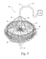
- FIG. 3 Another embodiment of a screened assembly 10 ′ is shown in FIG. 3 .
- the screened assembly 10 ′ includes the droplet generator in the form of the spray nozzle 12 having the nozzle tip 12 t and the base end 12 b .
- the spray nozzle 12 is supported by and fluidly connected to the conduit 14 at the base end 12 b .
- the conduit 14 is also fluidly connected to a source of liquid culture medium 15 .
- the screened assembly 10 ′ also includes the screen 16 spaced apart, or distal, from the nozzle tip 12 t by a distance “D,” and supported on the conduit 14 by a screen support 18 ′.
- the open area 13 exists in this spaced apart area and includes the gaseous medium which intersects with the droplets from the spray nozzle 12 .
- the screen support 18 ′ is configured as a cage or tube that at least partially surrounds the spray nozzle 12 and serves to at least partially channel the entrained gaseous medium to the screen 16 .
- the screen support 18 ′ can take any shape and/or configuration and can be supported by means other than the conduit 14 , provided that the screen support includes openings for gas flow (e.g., openings 20 ) and provided it supports and maintains the screen 16 adjacent to and in spaced relation to the nozzle tip 12 t.
- the liquid culture medium 11 is pumped into the conduit 14 and dispensed from the nozzle 12 into the open area 13 intersecting with the gaseous medium (such as a CO 2 -containing gaseous medium in the case of most algae), forming a plurality of droplets from the liquid culture medium and entraining the gaseous medium therein.
- the droplets and entrained gaseous medium then impinge upon the screen 16 , substantially mixing the gaseous medium and the liquid culture medium and forming a gas-enriched discharge.
- a surfactant is also provided, the action of the droplets impinging on the screen 16 forms a gas-enriched discharge in the form of foam bubbles from the droplets, containing the gas in the bubble walls and interiors.
- FIG. 5 Another embodiment of a screened assembly 10 ′′ is shown in FIG. 5 .
- the screened assembly 10 ′′ includes a droplet generator in the form of a spray disc 22 actuated by a motor and capable of spinning at high speeds (thousands of revolutions per minute (“RPM”)), supported on a spindle 23 .
- a screen 16 ′ is disposed adjacent to disc 22 with an open area 13 ′ existing inside the perimeter of the circular screen 16 ′.
- the screen 16 ′ is in the shape of a band having a diameter approximately equal to that of the disc 22 .
- the screen 16 ′ is disposed coaxially around the disc 22 , and is supported by a screen support 18 ′′ having struts 18 s ′ attached to a conduit 14 ′.
- the conduit 14 ′ has an outlet 14 o and is fluidly connected to a source of liquid culture medium 15 .
- the screen 16 ′ can have a variety of shapes and be disposed anywhere adjacent to the disc 22 , provided that a substantial amount of the droplets generated by the spinning action of the disc 22 impinge upon the screen 16 ′.
- the screen 16 ′ can have an approximately spherical contour and be disposed above the disc 22 .
- the screen 16 ′ can be supported by a variety of means.
- the disc 22 can itself be the support for screen 16 ′, in which case the screen spins with the disc 22 .
- a support for the screen 16 ′ can be a second disc disposed coaxially to and above disc 22 and attached to the conduit 14 ′, having one or more openings for gas flow, and serving to at least partially channel the gaseous medium to the screen 16 ′.
- the disc 22 is engaged to spin at thousands of RPM and the liquid culture medium is pumped into the conduit 14 ′ and dispensed from the conduit outlet 14 o onto the spinning disc 22 in the presence of a gaseous medium of the open area 13 ′.
- the rotation of the disc 22 causes a plurality of droplets to form from the liquid culture medium and disperse from the disc 22 .
- the droplets entrain the gaseous medium and impinge upon the screen 16 ′ resulting in substantial mixing of the gaseous medium and the droplet liquid culture medium and formation of a gas-enriched discharge.
- surfactant there results formation of a gas-enriched discharge in the form of foam bubbles from the droplets, containing the gas in the bubble walls and interiors.
- Those of ordinary skill in the art will recognize that a variety of spinning disc and other types of sprayers or droplet generators can be used in conjunction with the present screened assemblies and variations thereof to produce the gas-enriched discharge as described.
- the gaseous medium can be disposed in a closed, open, or partially closed chamber; or it can be an exhaust stream from manufacturing and/or energy production, channeled to flow adjacent to the nozzle, and the like.
- the gaseous medium can be air.
- the gaseous medium can contain CO 2 , and will contain CO 2 if the biomass desired for cultivation is algae that require CO 2 as a nutrient for cultivation.
- multiple sources of the gas can be provided by, for example, disposing another conduit supplying the gaseous medium adjacent to the droplet generator and/or the screen.
- the present invention can be utilized to absorb the CO 2 and remove it from the gaseous medium through its use as a nutrient for the cultivated algae.
- the foregoing droplet generators found in the screened assemblies 10 , 10 ′, and 10 ′′ can be configured to produce a gas-enriched discharge in the form of a foam, such as the foam-generating nozzle described in U.S. Pat. No. 2,492,037 to Freeman et al, for example.
- foam-generating nozzles can also be used in the present methods to the extent they can mix the gaseous medium and the liquid culture medium approximately at a minimum as well as the droplet generators and screened assemblies described herein.
- each of the foregoing screened assemblies 10 , 10 ′, 10 ′′ are shown with one spray nozzle 12 or disc 22 and one screen 16 , 16 ′, but it should be understood that the screened assemblies are not limited to the use of one droplet generator per screen, or one screen per droplet generator. Rather, it should be understood that in the present system and method, a plurality of droplet generators can be used with one screen, and a plurality of screens can be used in series with one droplet generator.
- the screened assemblies can have a screen of sufficient size such that a plurality of droplet generators can be disposed in adjacent, spaced apart relation thereto.
- the foregoing screened assemblies 10 , 10 ′, 10 ′′ can be used in a variety of systems and/or apparatus such as, for example, with a liquid culture medium reservoir formed of natural or raceway ponds, and in greenhouses, bioreactors, and the like.
- a plurality of screened assemblies 10 , 10 ′, 10 ′′ and/or combinations of screened assemblies 10 , 10 ′, 10 ′′ can be used in the foregoing systems and/or apparatus.
- the screened assemblies can be arranged in a variety of configurations to optimize algal growth according to the particular apparatus and/or conditions. For example, algal growth can be increased in photobioreactors using one or more of the foregoing screened assemblies.
- FIG. 6 shows an exemplary photobioreactor in the form of bioreactor 24 , which is one form of a biomass cultivation system, in accordance with one embodiment of the present invention.
- the bioreactor 24 includes a chamber 26 having an upper end 28 , a lower end 30 , and a substantially cylindrical sidewall 32 defining a reservoir region 27 at the lower end 30 .
- the chamber 26 is illustrated herein as being substantially cylindrical, but it should be recognized that numerous shapes, sizes and/or configurations can be used, and that combinations of the same or different chambers can be used in series and/or in parallel.
- the chamber 26 can be made from a material that is capable of containing a liquid culture medium in the reservoir region 27 and capable of withstanding the process conditions used in the bioreactor.
- the chamber 26 or a portion thereof can be formed from a material that is capable of transmitting light in the photoactive wavelength range into the chamber in order to drive photosynthesis of the algae or other biomass therein, such as, for example, glass, polymeric materials, composite materials, and the like.
- Suitable polymeric materials include, but are not limited to, polyethylene, polystyrene, polycarbonate, and the like.
- light in the photoactive wavelength range can be provided from a source other than sunlight, for example, one or more incandescent and/or fluorescent light bulbs or other light sources 52 .
- Such light sources 52 can be disposed in the chamber 26 and/or external to chamber 26 (if the chamber is constructed of material that transmits light in the photoactive wavelength range). If the chamber 26 is constructed of a material other than one that transmits light in the photoactive range, then such light bulbs can be disposed in the interior of the chamber 26 .
- the bioreactor 24 includes various conduits fluidly connected to the chamber 26 for introducing raw materials into, for discharging processed materials from, and/or for re-circulating processed materials through the chamber 26 , as desired or necessary.
- the conduits can be unitary, integral pieces, or alternatively a plurality of interconnecting unitary, integral pieces.
- valves 40 can be operatively connected to each of the various conduits to regulate the flow of material in and out of the chamber, or back into the chamber for further enrichment with CO 2 .
- the valves 40 disclosed herein can be manual or automatic.
- a first inlet conduit 34 is disposed at the lower end 30 , and is adapted to introduce various raw materials (e.g., water, nutrients, algae, optional surfactant, and the like) into the reservoir region 27 as necessary or desired. It should be recognized that other raw materials can be used, and the selection and optimization of such materials can be determined by those of ordinary skill in the art using no more than routine experimentation.
- a second inlet conduit 36 is disposed adjacent to the upper end 28 , and is adapted to introduce a gaseous medium into the chamber 26 (for example, a CO 2 -containing exhaust stream from a power plant, air, and the like).
- a vent conduit 42 is disposed at or adjacent to upper end 28 , and is adapted to discharge the gaseous medium from the chamber 26 as needed or desired to regulate the composition and/or pressure of the gaseous medium in the chamber.
- a discharge conduit 44 is fluidly connected to the chamber 26 and to a re-circulating conduit 38 , which is disposed in the sidewall 32 above the level of the reservoir region 27 , and which extends at least partially into the chamber 26 .
- the discharge conduit 44 is disposed at the bottom of reservoir region 27 , but it should be understood that discharge conduit 44 can be disposed in multiple locations in the reservoir region 27 , and in particular it can extend into the reservoir region 27 to provide discharge of liquid culture medium adjacent to the surface of the reservoir region 27 .
- the re-circulating conduit 38 is adapted to receive the liquid culture medium from the chamber 26 via the discharge conduit 44 for re-circulation and further enrichment with gas, such as CO 2 .
- a recovery conduit 46 is fluidly connected to the discharge conduit 44 between a pump 48 and the chamber 26 , which is adapted to discharge the liquid culture medium for further processing to produce commercial products.
- the pump 48 is operatively connected to the discharge conduit 44 to pump the liquid culture medium through the discharge conduit 44 and into the recovery conduit 46 , or into the chamber 26 for re-circulation and further enrichment with the gas, such as CO 2 .
- the valves 40 can be operatively connected to the conduits 44 , 46 to regulate the flow of liquid culture medium from the chamber 26 and into the recovery conduit 46 , or back into the chamber 26 .
- conduits can be made from one or more materials that are capable of containing a liquid culture medium, capable of withstanding the process conditions used in the bioreactor, and optionally capable of transmitting light. Suitable materials for the conduits include the same materials discussed above with respect to the chamber 26 .
- the various conduits are illustrated herein as substantially tubular, and having a circular cross-section, but it should be understood that multiple shapes, sizes and/or configurations can be used. If desired or necessary, the conduits or any portion thereof can be constructed of materials that do not transmit light in the photoactive range, to accommodate the light-independent reactions of photosynthesis (also sometimes referred to as “dark reactions”).
- a strainer system 50 can be operatively connected to the discharge conduit 44 between the chamber 26 and the pump 48 , in order to strain the liquid culture medium flowing through the discharge conduit 44 .
- the screened assembly 10 ′ disposed at the terminal end 38 t of the re-circulating conduit 38 is the screened assembly 10 ′ previously discussed and detailed.
- the screened assembly 10 ′ is disposed substantially in the center and at the lower end 30 of the chamber 26 .
- the screened assembly 10 ′ can be disposed anywhere in the chamber 26 , provided that when in operation the nozzle 12 is positioned above the level of the reservoir region 27 .
- screened assembly 10 ′ is shown in the chamber 26 , it should be understood that a plurality of screened assemblies 10 , 10 ′, 10 ′′ can be used in the present system and method, in multiple different operable configurations and/or combinations, and that the size and location of the screened assemblies 10 , 10 ′, 10 ′′ can vary. If desired or necessary, additional mechanical supports can be disposed in the chamber 26 for nozzle assemblies, interior lights, discs, screen, and the like.
- a heater/heat exchanger (not illustrated) can be operatively connected to the chamber 26 for regulating the temperature of the bioreactor 24 ;
- a supplemental light source can be disposed in the interior or exterior of the chamber 26 in order to transmit light into the chamber 26 when sunlight is not available and/or during operation;
- a controller (not illustrated) can be operatively attached to the pump, automatic valves and heater; and
- a source of power (not illustrated) can be operatively connected to all of the foregoing in order to supply power for operating any automatic features of the bioreactor 24 .
- bioreactor 24 will now be explained with reference to FIGS. 6 and 7 and using the example of cultivating algae with the introduction of CO 2 gas and light.
- the bioreactor 24 can be operated on a continuous basis, or in batches.
- a sufficient amount of gaseous medium from an external source such as the flue emissions from a coal-burning power plant and corresponding CO 2 contained therein, is introduced into the chamber 26 via the second inlet conduit 36 .
- the CO 2 concentration is about 2% to about 6%, by volume, at a pressure of approximately atmospheric pressure in the chamber.
- the pressure and concentration of CO 2 can be varied as desired or necessary, and that additional gases, including air, can be introduced via the second inlet conduit 36 if desired or necessary in order to maintain the desired gas composition and/or pressure in the chamber.
- the vent conduit 42 can be used to discharge the gaseous medium from the chamber 26 as needed or desired to maintain the desired chamber pressure and gaseous medium composition.
- additional conduits can be fluidly connected to the chamber 26 in order to facilitate regulation of the gaseous and/or liquid culture medium in the chamber at desired and/or optimum conditions.
- raw materials e.g., water, algae, nutrients, optionally a surfactant, and the like
- Power to the system is turned on, activating the pump 48 , and the liquid culture medium is then drawn into the discharge conduit 44 and into the chamber 26 via the re-circulating conduit 38 .
- the droplet generator such as for example the spray nozzle 12 , discharges the liquid culture medium as a plurality of droplets, and the droplets entrain the gaseous medium in the chamber (which includes gas such as for example CO 2 ), and impinge upon the screen 16 shortly thereafter.
- the gas-enriched discharge disperses into the lighted chamber around the screened assembly 10 ′.
- more algae in close proximity to CO 2 can receive sufficiently intense light for photosynthesis during the period of time from gas-enriched discharge emergence until the discharged liquid medium falls back and dissolves into the liquid culture medium in the reservoir region 27 .
- the gas-enriched discharge can emerge from the screen in the form of a foam comprised of a plurality of substantially transparent “wet” bubbles.
- the bubbles comprise diameters in the range of about 3 millimeters (mm) to about 30 mm, with an average diameter of about 5 mm to about 10 mm.
- the walls of the bubbles comprise a liquid culture medium volume fraction of about 4% to about 12% of the total volume of the bubbles.
- the liquid culture medium that makes up the walls has substantially increased concentration of CO 2 , and the interiors of the bubbles contain CO 2 .
- the liquid culture medium can be pumped to and discharged from the droplet generator in bursts (for example, about 20 to 120 seconds per burst) to conserve energy and to allow accumulation of a collection of foam of desirable thickness (for example, about 3 to 10 centimeters) on the surface of the liquid culture medium in reservoir region 27 .
- mechanical supports (not illustrated) for the foam can be disposed horizontally or at angles above the level of the liquid culture medium in reservoir region 27 , on which the foam can accumulate and from which the foam can drain back into the liquid culture medium in reservoir region 27 over a desirable period of time (about 10 minutes to about 30 minutes).
- the algae can continue to be in close proximity to the CO 2 present in the bubble walls and the interior of the bubbles.
- the foam acts as a blanket, which reduces the escape of CO 2 from the liquid culture medium in the reservoir, thereby further increasing the duration of contact of CO 2 with algae.
- the liquid culture medium includes a surfactant
- it can be an additive such as a liquid detergent, or can be a natural component of the algae, or both.
- surfactants that can be utilized with algae include but are not limited to vegetable oil based surfactants, any biocompatible surfactant, and/or shampoos.
- the liquid culture medium with the surfactant is dispensed from the droplet generator in the presence of light, and in the presence of a gaseous medium (such as CO 2 ), forming a plurality of droplets of the liquid culture medium. The droplets entrain the gaseous medium and impinge upon a screen shortly thereafter, resulting in substantially increased mixing of the gaseous and droplet liquid culture mediums.
- a gaseous medium such as CO 2
- the gas-enriched discharge emerges from the screen in the form of foam bubbles, having walls made up of liquid culture medium having substantially increased concentration of CO 2 in comparison to the concentration of CO 2 in the droplets of liquid culture medium prior to impinging upon the screen, and also having hollow interiors containing the gaseous medium.
- the foam bubbles have substantially larger volume than the droplets, effectively distributing the algae over a larger space, thereby further reducing the light shading of algae by other algae.
- the foam bubble walls are relatively thin, further reducing the average light path length through the liquid culture medium, thereby allowing the algae to receive light of higher intensity.
- the foam bubbles have a substantial surface area of liquid culture medium that can be contacted by the CO 2 present in both the exterior gaseous medium and the hollow interior of the foam bubbles, thereby allowing additional carbon transfer to the algae, beyond the amount available from the increased concentration of CO 2 within the foam bubble walls.
- the foam bubbles can be sustained in space for a substantially longer period of time than the non-foam gas-enriched discharge, substantially more light energy and CO 2 can be utilized by the algae in the foam bubble walls.
- These properties of the foam bubbles effectively allow the use of higher concentrations of algae in the liquid culture medium, which is highly desirable, while also promoting substantially increased carbon transfer and photosynthesis, resulting in substantially increased algal growth rates in relatively high cell culture densities, in comparison to other systems and methods.
- the bubbles can drain back into the liquid culture medium.
- the combination of higher algal concentration and higher algal growth rate contributes substantially to the increased biomass yield per unit of time that can be achieved in comparison to other systems and methods, and is relatively inexpensive in comparison thereto.
- the gas-enriched discharge and/or bubbles eventually fall back/drain and dissolve into the reservoir, and the process is repeated until the liquid culture medium in the reservoir is sufficiently enriched with algae for harvesting, at which point the liquid culture medium in the reservoir, or a portion thereof, is removed from the chamber via the discharge conduit 44 and the recovery conduit 46 .
- the reservoir region 27 can then be replenished with fresh raw materials via the first inlet conduit 34 .
- the screened assemblies can be used in a variety of cultivation systems and/or apparatus in addition to a photobioreactor.
- the screened assemblies can be used in natural ponds, raceway ponds, greenhouses, and the like, whether wholly or partially covered, or uncovered.
- a conduit can be disposed that supplies liquid culture medium (and/or the raw materials to form the liquid culture medium) to the pond, to a reservoir or sump in a greenhouse, etc., effectively allowing the pond, greenhouse reservoir or sump, etc. to serve as the reservoir region 27 .
- various pumps, agitators, and the like can be disposed in these cultivation systems, as would be understood by one of ordinary skill in the art.
- One or more CO 2 -containing gaseous streams e.g., air, flue gas from power plant, and the like
- CO 2 can be provided adjacent to the screened assemblies so that during operation, the CO 2 can be entrained and mixed in the liquid culture medium.
- the screened assemblies can be used to initially increase the concentration of CO 2 in water rather than in liquid culture medium, with or without the addition of a surfactant, not necessarily in the presence of light, for subsequent use of the CO 2 -enriched water, in bulk form or in the form of gas-enriched discharge or foam, to supply CO 2 to photosynthetic microorganisms and more generally plants, for the purpose of enhancing growth.
- a conduit can be disposed that, via a pump, supplies water from beneath the surface of the pond to a screened assembly disposed above the algae, which mixes the water with supplied CO 2 and sprays the mixture onto the algae.
- the system(s) and method(s) of the present invention disclosure can provide a more economical source of biofuels, a more economical source of oil that can be refined into biodiesel, and a more economical source of biomass that can be converted to ethanol.
- the biomass generated by the system(s) and method(s) of the present invention can be combusted directly or used to manufacture food or other useful products, mitigation of pollutants from power and processing plants, generation of oxygen, and the like, depending upon its particular implementation.
Abstract
A liquid culture medium containing photosynthetic organisms dispenses from a droplet generator combined with a screen in the presence of light, and in the presence of a gaseous medium to form a liquid culture medium gas-enriched with the gaseous medium. Specifically, the droplets exiting the droplet generator entrain the gaseous medium. The droplets and entrained gaseous medium then impinge upon a screen. As the droplets and entrained gaseous medium impinge upon the screen, the droplets splatter and change direction and velocity, thereby generating areas of high turbulence around the screen. This high turbulence results in additional and increased mixing of the gaseous medium to create a highly gas-enriched liquid culture medium which promotes improved growth rates and production of the photosynthetic organisms contained therein.
Description
This application claims priority to, and the benefit of, co-pending U.S. Provisional Application 60/923,306, filed Apr. 13, 2007, for all subject matter common to both applications. The disclosure of said provisional application is hereby incorporated herein by reference in its entirety.
The present invention relates to a biomass cultivation system, and more particularly to a system capable of generating a gas-enriched liquid mixture containing a biomass in a suitable manner for cultivation of that biomass.
It is well known that the photosynthesis of microorganisms such as algae consumes carbon dioxide (hereinafter “CO2”) and generates oxygen (hereinafter “O2”). Algae are considered efficient converters of CO2 and they have been cultivated using a variety of techniques. The primary nutrient requirements of algae are sunlight and carbon, CO2 being the principal source of carbon. Other microorganisms may require other nutrients.
Biomass resulting from the photosynthesis of algae can be burned directly as fuel, or it can be processed further (e.g., dewatering, drying, etc.) to produce many other products of commercial and/or environmental value. For example, algae have been cultivated artificially for such diverse purposes as the cultivation of food (i.e., protein residues) for animals and humans; ingredients for cosmetics and human health foods; refined/fermented biofuels (e.g., biodiesel, ethanol, methanol, and the like); the treatment of sewage and waste waters; and the accumulation of radioactive wastes.
Various methods and equipment have been employed to culture algae. However, attempts to make the cultivation of microorganisms commercially viable have been limited by the amount of CO2 that can be incorporated into the culture medium, the length of time the culture medium is exposed to light in the wavelength range that drives the light-dependent processes of photosynthesis (about 400 to about 700 nanometers (“nm”)), and the degree to which light can penetrate the culture medium. Like many plants, algae are quite sensitive to the amount and type of light. Excessive light intensity can damage and kill algal cells. Insufficient light can result in low levels of photosynthesis and consequently reduced growth rates.
Perhaps the simplest procedures for cultivating algae have involved the use of shallow open ponds exposed to sunlight, whether man-made (hereinafter “raceway” ponds) or natural. Because sunlight can only penetrate the pond water to a limited depth, the raceway ponds are constructed to be relatively shallow to maximize the exposure of the algae to sunlight. Paddle wheels generate water turbulence, which increases the incorporation of CO2 into the water, and circulates the algae back to the surface at a regular frequency, thereby increasing the exposure of the algae to sunlight. As a result, raceway ponds provide somewhat improved algae growth in comparison to natural ponds, but this form of algae cultivation is still considered insufficient for producing feedstock for commodity products.
Another approach has involved cultivating algae in wholly and/or partially covered trenches and ponds, optionally having electrically powered pumps and agitators. These configurations reduce the chances of contamination of the culture and permit more accurate control of temperature, respiration and other parameters. However, such configurations still fall short in providing adequate and uniform amounts of CO2 and light to the algal cells.
Increased algal cultivation rates can be achieved in photobioreactors, which provide improved environmental control because they are not open to the atmosphere. However, algal cultivation in photobioreactors is still limited by CO2 concentration and/or exposure to light. Thus, a consideration for modern photobioreactors involves providing a means for uniformly exposing the cells in the algal culture to the optimum amount of light and/or CO2. Some of the efforts include varying the configuration of the photobioreactor chamber(s) (e.g., horizontal tubular chambers, vertical tubular chambers, “airlift” photobioreactors, various arrays of tubular chambers, and the like); improving the photomodulation of the algae in the culture medium; and providing turbulence in the liquid media to both incorporate more CO2 and increase the frequency with which the algae contact light (e.g., by pumping and/or spraying the liquid media into the chamber in the presence of CO2; by injecting CO2 into the liquid media; by disposing the liquid media onto mechanical supports arranged spatially to minimize mutual shading; and the like).
In addition to the provision of a uniform and constant supply of light, cell culture density and the light path length through the culture medium can influence algal growth rates. As in conventional fermentation processes, it is usually desirable to obtain as high a rate of cell growth in as high a density of cell culture as possible, to maximize the amount of biomass produced per unit of time. Many of the same considerations apply to algal cultures as to bacterial cultures. For example, in addition to the light requirements, one must take into account the competition for nutrients, respiratory demands, viscosity and pumpability of the culture medium, and the like. However, an extremely high cell culture density results in cells more than a few millimeters from the light source being effectively shielded from the light. Also, as light travels through the liquid culture medium, it gets attenuated. Simply increasing the light intensity will not overcome these problems, because highly intense light can damage or kill cells.
To address these problems, particularly for industrial applications involving high-density microbial cultures that are amenable to continuous or large-scale batch recovery operations, photobioreactors have been designed that have closely spaced, large, transparent walls defining a light path and a fluid chamber within which the algal culture is contained. The transparent walls are illuminated with an appropriate light source to sustain the photosynthetic reactions of the cells. However, these configurations are relatively costly.
There is a need for a biomass cultivation system providing sufficient algal growth inexpensively enough to enable cultivation of biomass for commodity products. The present invention is directed toward further solutions to address this need, in addition to having other desirable characteristics.
In accordance with one embodiment of the present invention, a biomass cultivation system includes a screened assembly configured to emit a gas-enriched discharge mixture during operation. A liquid culture medium containing at least one photosynthetic microorganism can be supplied to the screened assembly. A gaseous medium can be supplied to the screened assembly. A liquid culture medium reservoir can be positioned to receive the gas-enriched discharge mixture discharged from the screened assembly. The screened assembly can include a droplet generator with the liquid culture medium supplied thereto, the droplet generator having a discharge path along which emerging droplets travel, and a screen disposed to intersect the discharge path of the droplet generator. The emerging droplets in the discharge path can be exposed to the gaseous medium and the emerging droplets impinge upon the screen forming the gas-enriched discharge mixture.
In accordance with example aspects and embodiments of the present invention, the at least one photosynthetic microorganism includes an algal organism. The gaseous medium includes CO2, air, or both. The liquid culture medium can be supplied by the liquid culture medium reservoir. A pump can be provided and configured to pump the liquid culture medium through the screened assembly. A light source can be positioned to illuminate the liquid culture medium, and/or the light source can be sunlight. The light source can supply light in a wavelength range of about 400 nm to about 700 nm to illuminate the liquid culture medium. The screen can include a wire mesh structure.
In accordance with further example aspects and embodiments of the present invention, the liquid culture medium can further include a surfactant in an amount sufficient to generate a foam gas-enriched mixture upon impinging on the screen. The surfactant can be, for example, vegetable oil or a derivative, shampoo, detergent, or any combination of some or all of these. A bioreactor can house the screened assembly, and/or the liquid culture medium reservoir, and/or a light source for illumination of the liquid culture medium. The liquid culture medium reservoir can be a natural pond, a raceway pond, a greenhouse reservoir, or a bioreactor reservoir.
In accordance with further example aspects and embodiments of the present invention, the system can be configured to pump the liquid culture medium through the screened assembly in periodic bursts.
In accordance with further example aspects and embodiments of the present invention, a method of cultivating a biomass using a biomass cultivation system is provided. The method can include providing the biomass cultivation system. A screened assembly can be configured to emit a gas-enriched discharge mixture during operation. A liquid culture medium can contain at least one photosynthetic microorganism supplied to the screened assembly. A gaseous medium can be supplied to the screened assembly. A liquid culture medium reservoir can be positioned to receive the gas-enriched discharge mixture discharged from the screened assembly. The screened assembly can include a droplet generator with the liquid culture medium supplied thereto, the droplet generator having a discharge path along which emerging droplets travel, and a screen disposed to intersect the discharge path of the droplet generator, wherein the emerging droplets in the discharge path are exposed to the gaseous medium and the emerging droplets impinge upon the screen forming the gas-enriched discharge mixture. The method can further include pumping the liquid culture medium through the screened assembly to generate the gas-enriched discharge mixture. The gas-enriched discharge mixture can be collected in the liquid culture medium reservoir.
In accordance with further example aspects and embodiments of the present invention, the at least one photosynthetic microorganism can include an algal organism. The gaseous medium can include CO2, air, or both. The liquid culture medium can be supplied by the liquid culture medium reservoir. The liquid culture medium can be illuminated with a light source, for example in a wavelength range of about 400 nm to about 700 nm for algae. The gas-enriched discharge mixture discharged from the screened assembly can be illuminated. The screen can be a wire mesh structure. A surfactant can be added to the liquid culture medium in an amount sufficient to generate a foam gas-enriched mixture upon impinging on the screen, and can be, for example, vegetable oil or a derivative, shampoo, detergent, or any combination of some or all of these. The liquid culture medium reservoir can be a natural pond, a raceway pond, a greenhouse reservoir, or a bioreactor reservoir. The liquid culture medium can be pumped through the screened assembly in periodic bursts.
In accordance with further example aspects and embodiments of the present invention a method of biomass cultivation can include providing a liquid culture medium containing at least one photosynthetic microorganism and a surfactant. The liquid culture medium can be arranged into a plurality of cells having walls formed of the liquid culture medium and containing a gaseous medium therein. A predetermined intensity and wavelength range of light suitable as a nutrient to the photosynthetic microorganism can be provided. The plurality of cells can be substantially transparent to the light, and can support growth of the photosynthetic microorganism.
In accordance with further example aspects and embodiments of the present invention, the plurality of cells can be arranged to have a diameter of about 3 mm to about 30 mm. The walls of the plurality of cells can include a liquid culture medium volume fraction of about 4% to about 12% of a total volume of the plurality of cells.
These and other characteristics of the present invention will be more fully understood by reference to the following detailed description in conjunction with the attached drawings, in which:
Other features and advantageous aspects of the disclosure will become apparent from the following detailed description of embodiments of the disclosure herein, which are provided as examples. It is to be understood that various features of the embodiments could be utilized independent of other features. In other words, not every feature of each embodiment need be incorporated in a given device or a manufacturing method in practicing the present disclosure. Thus, the illustrated embodiments are intended as examples and are not to be construed as limiting.
A particular problem not yet solved in the art of cultivation of photosynthetic organisms for use as fuel and other commodity products is the inability to economically provide sufficient amounts or concentrations of CO2 and desired light to the organisms during the photosynthetic process. The present system and method of operation overcome this problem, thereby providing substantially increased growth rates for the photosynthetic organisms, including in relatively highly concentrated cell cultures, due to an improved approach for increasing gas levels available as a nutrient to biomass cultures while increasing exposure of the biomass cultures to light. Use of the inventive system and method substantially increase biomass yield per unit of time in comparison to other systems and methods in an economically efficient and feasible manner.
Illustrative embodiments of the present invention relate to a system providing improved methods of cultivating photosynthetic organisms. The system makes use of a liquid culture medium dispensed from a droplet generator combined with a screen in the presence of light, and in the presence of a gaseous medium (for most algae the gaseous medium is or includes CO2), resulting in the formation of a liquid culture medium gas-enriched with the gaseous medium. Specifically, the motion and surface area of droplets exiting the droplet generator result in substantial entrainment of the gaseous medium. The droplets and entrained gaseous medium then impinge upon a screen shortly after emerging from the droplet generator. As the droplets and entrained gaseous medium impinge upon the screen, some of the droplets splatter and change direction and velocity, thereby generating areas of high turbulence around the wires of the screen. This high turbulence results in additional and increased mixing of the gaseous medium and droplet liquid culture mediums. As a result, the droplets flowing through the screen emerge as a gas-enriched discharge dispersing into the surrounding space. The dispersed droplets contain a concentration of gas that is substantially increased in comparison to the concentration of gas in the droplets prior to passing through the screen. The gas-enriched discharge can then be collected in a reservoir and re-supplied as the liquid culture medium in a continuous loop, which further increases the amount of CO2 mixed into the medium and further increases exposure of the organisms in the dispersed droplets of the medium to light during cultivation.
The substantial mixing of gas (such as CO2) and liquid culture medium (such as a medium containing algae) that occurs with the system and method of the present invention results in a substantial improvement over the mixing that can be achieved by prior attempts of spraying without the combined droplet generator and screen utilized in the present system, and promotes an unexpectedly high growth rate of the algae achievable in comparison with other known systems and methods.
“Liquid culture medium”, as utilized herein, refers to a liquid containing at least one photosynthetic microorganism that is capable of supporting reproduction of the at least one microorganism (hereinafter “liquid culture medium”). The photosynthetic microorganism can include a form of algae, or can be another form of microorganism, such that the present invention is not limited only to use with algal cultivation.
“Photosynthetic organism,” as utilized herein and without alteration from its conventional meaning, refers to any organism capable of photosynthetic growth in a liquid culture medium, including but not limited to, algae. For the ease of explanation, “photosynthetic organism” will be referred to hereinafter as “algae” and/or “algal,” depending on the context. Such a liquid culture medium can comprise, for example, water, algae, nutrients, and the like. However, the present invention is not limited to the exemplary use of algae as the photosynthetic organism, but can instead be utilized by other biomass organisms that could be cultivated in the environment provided by the system.
“Biomass”, as utilized herein and without alteration from its conventional meaning, refers to the mass and/or accumulating mass of photosynthetic organisms resulting from the cultivation of such organisms using a variety of techniques. Various forms and species of micro- and macro algae include but are not limited to chlorella, spirulina and kelp, and are exemplary of biomass and are presently cultivated for some of these uses.
According to one embodiment of the present invention, and looking at FIG. 1 , a screened assembly 10 for use in a biomass cultivation system is shown. In accordance with this particular example embodiment, the screened assembly 10 includes a droplet generator in the form of spray nozzle 12 that has a nozzle tip 12 t and a base end 12 b. The spray nozzle 12 is supported by, and fluidly connected to, a conduit 14 at the base end 12 b. The conduit 14 is fluidly connected to a source of liquid culture medium, which can be a collection reservoir as later described, or can be another source. The screened assembly 10 also includes a screen 16 spaced apart, or distal, from the nozzle tip 12 t by a distance “D,” and supported on the conduit 14 by a screen support 18. Depending on various design and operating parameters of the spray nozzle 12, such as the angle and volume of discharge and the size of the droplets, distance D can be about 2 inches to about 6 or more inches. The screen 16 intersects with the droplets discharged from the spray nozzle 12. The screen 16 is formed of a mesh of woven wire having a selected spacing, pattern, and diameter. An exemplary suitable wire mesh has a spherical contour and a cross-sectional wire diameter of about 1/16 inch to about ⅛ inch, with about 2 to 6 wires per inch in a crisscross pattern. Those of ordinary skill in the art will recognize that the distance D, the contour of the mesh, the wire diameter, pattern, and spacing of the wires, can be varied as desired or needed to influence the properties and characteristics of the droplets emitted therefrom.
The screen support 18 includes a plurality of struts 18 s extending from the conduit 14 to the screen 16 and defining a plurality of openings 20 disposed between the struts 18 s. Although the screen support 18 is illustrated herein as a plurality of struts, it should be recognized that the screen support can be of any shape and/or configuration and can be supported by means other than the conduit 14, provided that the screen support includes openings for gas flow (e.g., openings 20) and provided it supports and maintains the screen 16 adjacent to and in spaced relation to the nozzle tip 12 t. The spaced relation between the screen 16 and the nozzle tip 12 t creates an open area 13 where a gaseous medium can be supplied. The gaseous medium can be supplied through an injection process, or through general exposure of the screened assembly 10 to an environment containing the gaseous medium, to intersect with the droplets. In the example embodiment discussed herein where the liquid culture medium contains an algal biomass, the use of CO2 gas either supplied directly in a gaseous medium or as it naturally occurs in the air as the gaseous medium will suffice to fill the open area 13.
In operation, as shown in FIG. 2 , a liquid culture medium 11 is pumped into the conduit 14 and dispensed from the nozzle 12 into contact with a gaseous medium (such as a CO2-containing gaseous medium), the liquid culture medium being converted in the nozzle into a plurality of droplets. The droplets then pass through the open area 13, intersecting with and entraining the gaseous medium therein, and impinge upon the screen 16, substantially mixing the entrained gaseous medium with the liquid culture medium droplets to form a gas-enriched discharge. If a surfactant is also provided, the action of the droplets impinging on the screen 16 forms a gas-enriched discharge of foam bubbles, containing the gas in the bubble walls and interiors.
Another embodiment of a screened assembly 10′ is shown in FIG. 3 . The screened assembly 10′ includes the droplet generator in the form of the spray nozzle 12 having the nozzle tip 12 t and the base end 12 b. The spray nozzle 12 is supported by and fluidly connected to the conduit 14 at the base end 12 b. The conduit 14 is also fluidly connected to a source of liquid culture medium 15. The screened assembly 10′ also includes the screen 16 spaced apart, or distal, from the nozzle tip 12 t by a distance “D,” and supported on the conduit 14 by a screen support 18′. Again, the open area 13 exists in this spaced apart area and includes the gaseous medium which intersects with the droplets from the spray nozzle 12. In the example embodiment, the screen support 18′ is configured as a cage or tube that at least partially surrounds the spray nozzle 12 and serves to at least partially channel the entrained gaseous medium to the screen 16. Again, although configured in the present embodiment as a cage or tube, it should be recognized that the screen support 18′ can take any shape and/or configuration and can be supported by means other than the conduit 14, provided that the screen support includes openings for gas flow (e.g., openings 20) and provided it supports and maintains the screen 16 adjacent to and in spaced relation to the nozzle tip 12 t.
As shown in FIG. 4 , in operation, the liquid culture medium 11 is pumped into the conduit 14 and dispensed from the nozzle 12 into the open area 13 intersecting with the gaseous medium (such as a CO2-containing gaseous medium in the case of most algae), forming a plurality of droplets from the liquid culture medium and entraining the gaseous medium therein. The droplets and entrained gaseous medium then impinge upon the screen 16, substantially mixing the gaseous medium and the liquid culture medium and forming a gas-enriched discharge. If a surfactant is also provided, the action of the droplets impinging on the screen 16 forms a gas-enriched discharge in the form of foam bubbles from the droplets, containing the gas in the bubble walls and interiors.
Another embodiment of a screened assembly 10″ is shown in FIG. 5 . As shown, the screened assembly 10″ includes a droplet generator in the form of a spray disc 22 actuated by a motor and capable of spinning at high speeds (thousands of revolutions per minute (“RPM”)), supported on a spindle 23. A screen 16′ is disposed adjacent to disc 22 with an open area 13′ existing inside the perimeter of the circular screen 16′. As shown, the screen 16′ is in the shape of a band having a diameter approximately equal to that of the disc 22. The screen 16′ is disposed coaxially around the disc 22, and is supported by a screen support 18″ having struts 18 s′ attached to a conduit 14′. The conduit 14′ has an outlet 14 o and is fluidly connected to a source of liquid culture medium 15. It should be understood that the screen 16′ can have a variety of shapes and be disposed anywhere adjacent to the disc 22, provided that a substantial amount of the droplets generated by the spinning action of the disc 22 impinge upon the screen 16′. For example, to intercept patterns of droplet dispersion of a disc 22 of a particular design, the screen 16′ can have an approximately spherical contour and be disposed above the disc 22. The screen 16′ can be supported by a variety of means. For example, the disc 22 can itself be the support for screen 16′, in which case the screen spins with the disc 22. Alternatively, a support for the screen 16′ can be a second disc disposed coaxially to and above disc 22 and attached to the conduit 14′, having one or more openings for gas flow, and serving to at least partially channel the gaseous medium to the screen 16′.
In operation, the disc 22 is engaged to spin at thousands of RPM and the liquid culture medium is pumped into the conduit 14′ and dispensed from the conduit outlet 14 o onto the spinning disc 22 in the presence of a gaseous medium of the open area 13′. The rotation of the disc 22 causes a plurality of droplets to form from the liquid culture medium and disperse from the disc 22. The droplets entrain the gaseous medium and impinge upon the screen 16′ resulting in substantial mixing of the gaseous medium and the droplet liquid culture medium and formation of a gas-enriched discharge. In the presence of surfactant, there results formation of a gas-enriched discharge in the form of foam bubbles from the droplets, containing the gas in the bubble walls and interiors. Those of ordinary skill in the art will recognize that a variety of spinning disc and other types of sprayers or droplet generators can be used in conjunction with the present screened assemblies and variations thereof to produce the gas-enriched discharge as described.
In the foregoing embodiments, the gaseous medium can be disposed in a closed, open, or partially closed chamber; or it can be an exhaust stream from manufacturing and/or energy production, channeled to flow adjacent to the nozzle, and the like. Alternatively, the gaseous medium can be air. Whether the gaseous medium is exhaust, air, or some other source, as previously stated herein it can contain CO2, and will contain CO2 if the biomass desired for cultivation is algae that require CO2 as a nutrient for cultivation. Furthermore, if desired or necessary to achieve desired levels of gas entrainment, multiple sources of the gas can be provided by, for example, disposing another conduit supplying the gaseous medium adjacent to the droplet generator and/or the screen. In the case that the gaseous medium is exhaust from a manufacturing plant and contains CO2, then the present invention can be utilized to absorb the CO2 and remove it from the gaseous medium through its use as a nutrient for the cultivated algae.
The foregoing droplet generators found in the screened assemblies 10, 10′, and 10″ can be configured to produce a gas-enriched discharge in the form of a foam, such as the foam-generating nozzle described in U.S. Pat. No. 2,492,037 to Freeman et al, for example. Those of ordinary skill in the art will recognize that other types of foam-generating nozzles can also be used in the present methods to the extent they can mix the gaseous medium and the liquid culture medium approximately at a minimum as well as the droplet generators and screened assemblies described herein. However, it should be noted that simply spraying the liquid culture medium using a droplet generator into a chamber or bioreactor with CO2 has been shown in its conventional arrangement to be insufficient to mix the CO2 with the liquid culture medium to the degree necessary to promote the requisite rate of algae growth as provided herein. The addition of the screen portion of the screened assembly is instrumental in the case of the Freeman nozzle in thoroughly mixing the liquid culture medium and the gaseous medium to the extent required for the increased algal growth rates.
Each of the foregoing screened assemblies 10, 10′, 10″ are shown with one spray nozzle 12 or disc 22 and one screen 16, 16′, but it should be understood that the screened assemblies are not limited to the use of one droplet generator per screen, or one screen per droplet generator. Rather, it should be understood that in the present system and method, a plurality of droplet generators can be used with one screen, and a plurality of screens can be used in series with one droplet generator. For example, the screened assemblies can have a screen of sufficient size such that a plurality of droplet generators can be disposed in adjacent, spaced apart relation thereto.
The foregoing screened assemblies 10, 10′, 10″ can be used in a variety of systems and/or apparatus such as, for example, with a liquid culture medium reservoir formed of natural or raceway ponds, and in greenhouses, bioreactors, and the like. In addition, a plurality of screened assemblies 10, 10′, 10″ and/or combinations of screened assemblies 10, 10′, 10″ can be used in the foregoing systems and/or apparatus. The screened assemblies can be arranged in a variety of configurations to optimize algal growth according to the particular apparatus and/or conditions. For example, algal growth can be increased in photobioreactors using one or more of the foregoing screened assemblies.
The bioreactor 24 includes various conduits fluidly connected to the chamber 26 for introducing raw materials into, for discharging processed materials from, and/or for re-circulating processed materials through the chamber 26, as desired or necessary. Those of skill in the art will recognize that the number, placement and shape of the conduits can vary, and that the conduits can be unitary, integral pieces, or alternatively a plurality of interconnecting unitary, integral pieces. When desired or necessary, valves 40 can be operatively connected to each of the various conduits to regulate the flow of material in and out of the chamber, or back into the chamber for further enrichment with CO2. The valves 40 disclosed herein can be manual or automatic.
In the present embodiment, a first inlet conduit 34 is disposed at the lower end 30, and is adapted to introduce various raw materials (e.g., water, nutrients, algae, optional surfactant, and the like) into the reservoir region 27 as necessary or desired. It should be recognized that other raw materials can be used, and the selection and optimization of such materials can be determined by those of ordinary skill in the art using no more than routine experimentation. A second inlet conduit 36 is disposed adjacent to the upper end 28, and is adapted to introduce a gaseous medium into the chamber 26 (for example, a CO2-containing exhaust stream from a power plant, air, and the like). A vent conduit 42 is disposed at or adjacent to upper end 28, and is adapted to discharge the gaseous medium from the chamber 26 as needed or desired to regulate the composition and/or pressure of the gaseous medium in the chamber.
At the reservoir region 27, a discharge conduit 44 is fluidly connected to the chamber 26 and to a re-circulating conduit 38, which is disposed in the sidewall 32 above the level of the reservoir region 27, and which extends at least partially into the chamber 26. As shown, the discharge conduit 44 is disposed at the bottom of reservoir region 27, but it should be understood that discharge conduit 44 can be disposed in multiple locations in the reservoir region 27, and in particular it can extend into the reservoir region 27 to provide discharge of liquid culture medium adjacent to the surface of the reservoir region 27. The re-circulating conduit 38 is adapted to receive the liquid culture medium from the chamber 26 via the discharge conduit 44 for re-circulation and further enrichment with gas, such as CO2. A recovery conduit 46 is fluidly connected to the discharge conduit 44 between a pump 48 and the chamber 26, which is adapted to discharge the liquid culture medium for further processing to produce commercial products. The pump 48 is operatively connected to the discharge conduit 44 to pump the liquid culture medium through the discharge conduit 44 and into the recovery conduit 46, or into the chamber 26 for re-circulation and further enrichment with the gas, such as CO2. The valves 40 can be operatively connected to the conduits 44, 46 to regulate the flow of liquid culture medium from the chamber 26 and into the recovery conduit 46, or back into the chamber 26.
The foregoing conduits can be made from one or more materials that are capable of containing a liquid culture medium, capable of withstanding the process conditions used in the bioreactor, and optionally capable of transmitting light. Suitable materials for the conduits include the same materials discussed above with respect to the chamber 26. The various conduits are illustrated herein as substantially tubular, and having a circular cross-section, but it should be understood that multiple shapes, sizes and/or configurations can be used. If desired or necessary, the conduits or any portion thereof can be constructed of materials that do not transmit light in the photoactive range, to accommodate the light-independent reactions of photosynthesis (also sometimes referred to as “dark reactions”). If desired, a strainer system 50 can be operatively connected to the discharge conduit 44 between the chamber 26 and the pump 48, in order to strain the liquid culture medium flowing through the discharge conduit 44.
In accordance with one example embodiment of the bioreactor 24, disposed at the terminal end 38 t of the re-circulating conduit 38 is the screened assembly 10′ previously discussed and detailed. The screened assembly 10′ is disposed substantially in the center and at the lower end 30 of the chamber 26. However, it should be understood that the screened assembly 10′ can be disposed anywhere in the chamber 26, provided that when in operation the nozzle 12 is positioned above the level of the reservoir region 27. In addition, although only one screened assembly 10′ is shown in the chamber 26, it should be understood that a plurality of screened assemblies 10, 10′, 10″ can be used in the present system and method, in multiple different operable configurations and/or combinations, and that the size and location of the screened assemblies 10, 10′, 10″ can vary. If desired or necessary, additional mechanical supports can be disposed in the chamber 26 for nozzle assemblies, interior lights, discs, screen, and the like.
Also if desired or necessary, a heater/heat exchanger (not illustrated) can be operatively connected to the chamber 26 for regulating the temperature of the bioreactor 24; a supplemental light source can be disposed in the interior or exterior of the chamber 26 in order to transmit light into the chamber 26 when sunlight is not available and/or during operation; a controller (not illustrated) can be operatively attached to the pump, automatic valves and heater; and a source of power (not illustrated) can be operatively connected to all of the foregoing in order to supply power for operating any automatic features of the bioreactor 24.
The operation of bioreactor 24 will now be explained with reference to FIGS. 6 and 7 and using the example of cultivating algae with the introduction of CO2 gas and light. The bioreactor 24 can be operated on a continuous basis, or in batches. In operation, a sufficient amount of gaseous medium from an external source, such as the flue emissions from a coal-burning power plant and corresponding CO2 contained therein, is introduced into the chamber 26 via the second inlet conduit 36. In an exemplar embodiment, the CO2 concentration is about 2% to about 6%, by volume, at a pressure of approximately atmospheric pressure in the chamber. It should be understood that the pressure and concentration of CO2 (or other desired gas) can be varied as desired or necessary, and that additional gases, including air, can be introduced via the second inlet conduit 36 if desired or necessary in order to maintain the desired gas composition and/or pressure in the chamber. Similarly, the vent conduit 42 can be used to discharge the gaseous medium from the chamber 26 as needed or desired to maintain the desired chamber pressure and gaseous medium composition. It should be understood that additional conduits can be fluidly connected to the chamber 26 in order to facilitate regulation of the gaseous and/or liquid culture medium in the chamber at desired and/or optimum conditions.
Various raw materials (e.g., water, algae, nutrients, optionally a surfactant, and the like) that make up the liquid culture medium are introduced into the reservoir region 27 via the first inlet conduit 34 until reaching a desired level below the level of the nozzle 12. Power to the system is turned on, activating the pump 48, and the liquid culture medium is then drawn into the discharge conduit 44 and into the chamber 26 via the re-circulating conduit 38.
The droplet generator, such as for example the spray nozzle 12, discharges the liquid culture medium as a plurality of droplets, and the droplets entrain the gaseous medium in the chamber (which includes gas such as for example CO2), and impinge upon the screen 16 shortly thereafter. As illustrated in FIG. 7 , the gas-enriched discharge disperses into the lighted chamber around the screened assembly 10′. As a result of the formation and dispersion of the droplets that occurs during this process, in the case of culturing algae, more algae in close proximity to CO2 can receive sufficiently intense light for photosynthesis during the period of time from gas-enriched discharge emergence until the discharged liquid medium falls back and dissolves into the liquid culture medium in the reservoir region 27. This is primarily because of a reduction in attenuation of the light due to the scattering of the droplets, and because of reduction of mutual shading by the algae due to the dispersion of the gas-enriched discharge in space. Also, this period of time can be lengthened, and the access of the algae to light and CO2 can be enhanced, by incorporation of a surfactant or other foaming agent into the liquid culture medium. Depending on the chemical composition and concentration of the foaming agent, the particular design characteristics of the screened assembly, and the velocity of the gas-enriched discharge emerging from the spray nozzle (or emerging from the spray disc, in the case of such embodiments), the gas-enriched discharge can emerge from the screen in the form of a foam comprised of a plurality of substantially transparent “wet” bubbles. In accordance with one example implementation of the present invention, the bubbles comprise diameters in the range of about 3 millimeters (mm) to about 30 mm, with an average diameter of about 5 mm to about 10 mm. The walls of the bubbles comprise a liquid culture medium volume fraction of about 4% to about 12% of the total volume of the bubbles. The liquid culture medium that makes up the walls has substantially increased concentration of CO2, and the interiors of the bubbles contain CO2.
If desired or necessary, the liquid culture medium can be pumped to and discharged from the droplet generator in bursts (for example, about 20 to 120 seconds per burst) to conserve energy and to allow accumulation of a collection of foam of desirable thickness (for example, about 3 to 10 centimeters) on the surface of the liquid culture medium in reservoir region 27. If desired or necessary, mechanical supports (not illustrated) for the foam can be disposed horizontally or at angles above the level of the liquid culture medium in reservoir region 27, on which the foam can accumulate and from which the foam can drain back into the liquid culture medium in reservoir region 27 over a desirable period of time (about 10 minutes to about 30 minutes). During the time the algae are suspended in the foam, they can continue to be in close proximity to the CO2 present in the bubble walls and the interior of the bubbles. As the foam drains, algae in the successive layers of bubbles at the top of the remaining foam pile can continue to remain relatively un-shaded and to receive sufficiently intense light for photosynthesis. Additionally, the foam acts as a blanket, which reduces the escape of CO2 from the liquid culture medium in the reservoir, thereby further increasing the duration of contact of CO2 with algae. These are highly desirable outcomes of this process, are inexpensive to implement, and contributory to the substantial increase in the growth of the biomass.
More specifically when the liquid culture medium includes a surfactant, it can be an additive such as a liquid detergent, or can be a natural component of the algae, or both. In fact, examples of surfactants that can be utilized with algae include but are not limited to vegetable oil based surfactants, any biocompatible surfactant, and/or shampoos. The liquid culture medium with the surfactant is dispensed from the droplet generator in the presence of light, and in the presence of a gaseous medium (such as CO2), forming a plurality of droplets of the liquid culture medium. The droplets entrain the gaseous medium and impinge upon a screen shortly thereafter, resulting in substantially increased mixing of the gaseous and droplet liquid culture mediums. Due to the presence of the surfactant, the gas-enriched discharge emerges from the screen in the form of foam bubbles, having walls made up of liquid culture medium having substantially increased concentration of CO2 in comparison to the concentration of CO2 in the droplets of liquid culture medium prior to impinging upon the screen, and also having hollow interiors containing the gaseous medium.
The foam bubbles have substantially larger volume than the droplets, effectively distributing the algae over a larger space, thereby further reducing the light shading of algae by other algae. The foam bubble walls are relatively thin, further reducing the average light path length through the liquid culture medium, thereby allowing the algae to receive light of higher intensity. The foam bubbles have a substantial surface area of liquid culture medium that can be contacted by the CO2 present in both the exterior gaseous medium and the hollow interior of the foam bubbles, thereby allowing additional carbon transfer to the algae, beyond the amount available from the increased concentration of CO2 within the foam bubble walls. Further, since the foam bubbles can be sustained in space for a substantially longer period of time than the non-foam gas-enriched discharge, substantially more light energy and CO2 can be utilized by the algae in the foam bubble walls. These properties of the foam bubbles effectively allow the use of higher concentrations of algae in the liquid culture medium, which is highly desirable, while also promoting substantially increased carbon transfer and photosynthesis, resulting in substantially increased algal growth rates in relatively high cell culture densities, in comparison to other systems and methods. The bubbles can drain back into the liquid culture medium. The combination of higher algal concentration and higher algal growth rate contributes substantially to the increased biomass yield per unit of time that can be achieved in comparison to other systems and methods, and is relatively inexpensive in comparison thereto.
The gas-enriched discharge and/or bubbles eventually fall back/drain and dissolve into the reservoir, and the process is repeated until the liquid culture medium in the reservoir is sufficiently enriched with algae for harvesting, at which point the liquid culture medium in the reservoir, or a portion thereof, is removed from the chamber via the discharge conduit 44 and the recovery conduit 46. The reservoir region 27 can then be replenished with fresh raw materials via the first inlet conduit 34. Also, the screened assemblies can be used in a variety of cultivation systems and/or apparatus in addition to a photobioreactor. For example, the screened assemblies can be used in natural ponds, raceway ponds, greenhouses, and the like, whether wholly or partially covered, or uncovered. To do so, a conduit can be disposed that supplies liquid culture medium (and/or the raw materials to form the liquid culture medium) to the pond, to a reservoir or sump in a greenhouse, etc., effectively allowing the pond, greenhouse reservoir or sump, etc. to serve as the reservoir region 27. If desired or necessary, various pumps, agitators, and the like can be disposed in these cultivation systems, as would be understood by one of ordinary skill in the art. One or more CO2-containing gaseous streams (e.g., air, flue gas from power plant, and the like) can be provided adjacent to the screened assemblies so that during operation, the CO2 can be entrained and mixed in the liquid culture medium. Also, the screened assemblies can be used to initially increase the concentration of CO2 in water rather than in liquid culture medium, with or without the addition of a surfactant, not necessarily in the presence of light, for subsequent use of the CO2-enriched water, in bulk form or in the form of gas-enriched discharge or foam, to supply CO2 to photosynthetic microorganisms and more generally plants, for the purpose of enhancing growth. For example, in an environment in which algae are growing at the surface of a pond, a conduit can be disposed that, via a pump, supplies water from beneath the surface of the pond to a screened assembly disposed above the algae, which mixes the water with supplied CO2 and sprays the mixture onto the algae.
The system(s) and method(s) of the present invention disclosure can provide a more economical source of biofuels, a more economical source of oil that can be refined into biodiesel, and a more economical source of biomass that can be converted to ethanol. The biomass generated by the system(s) and method(s) of the present invention can be combusted directly or used to manufacture food or other useful products, mitigation of pollutants from power and processing plants, generation of oxygen, and the like, depending upon its particular implementation.
Numerous modifications and alternative embodiments of the present invention will be apparent to those skilled in the art in view of the foregoing description. Accordingly, this description is to be construed as illustrative only and is for the purpose of teaching those skilled in the art the best mode for carrying out the present invention. Details of the structure may vary substantially without departing from the spirit of the present invention, and exclusive use of all modifications that come within the scope of the appended claims is reserved. It is intended that the present invention be limited only to the extent required by the appended claims and the applicable rules of law.
It is also to be understood that the following claims are to cover all generic and specific features of the invention described herein, and all statements of the scope of the invention which, as a matter of language, might be said to fall therebetween.
Claims (16)
1. A biomass cultivation system, comprising:
a screened assembly configured to emit a gas-enriched discharge mixture during operation;
a liquid culture medium containing at least one photosynthetic microorganism supplied to the screened assembly;
a gaseous medium supplied to the screened assembly; and
a liquid culture medium reservoir positioned to receive the gas-enriched discharge mixture discharged from the screened assembly;
wherein the screened assembly comprises:
a droplet generator with the liquid culture medium supplied thereto, the droplet generator having a discharge path along which emerging droplets travel; and
a screen disposed to intersect the discharge path of the droplet generator;
wherein the emerging droplets in the discharge path are exposed to the gaseous medium and the emerging droplets impinge upon the screen forming the gas-enriched discharge mixture.
2. The biomass cultivation system of claim 1 , wherein the at least one photosynthetic microorganism comprises an algal organism.
3. The biomass cultivation system of claim 1 , wherein the gaseous medium comprises CO2, air, or both.
4. The biomass cultivation system of claim 1 , wherein the liquid culture medium is supplied by the liquid culture medium reservoir.
5. The biomass cultivation system of claim 1 , further comprising a pump configured to pump the liquid culture medium through the screened assembly.
6. The biomass cultivation system of claim 1 , further comprising a light source positioned to illuminate the liquid culture medium.
7. The biomass cultivation system of claim 1 , wherein a light source supplies light in a wavelength range of about 400 nm to about 700 nm to illuminate the liquid culture medium.
8. The biomass cultivation system of claim 1 , wherein the gas-enriched discharge mixture discharged from the screened assembly is illuminated by sunlight, artificial light, or both.
9. The biomass cultivation system of claim 1 , wherein the screen comprises a wire mesh structure.
10. The biomass cultivation system of claim 1 , wherein the liquid culture medium further comprises a surfactant in an amount sufficient to generate a foam gas-enriched mixture upon impinging on the screen.
11. The biomass cultivation system of claim 1 , wherein the liquid culture medium further comprises a surfactant in an amount sufficient to generate a foam gas-enriched mixture upon impinging on the screen, the surfactant comprising vegetable oil or a derivative, shampoo, detergent, or any combination thereof.
12. The biomass cultivation system of claim 1 , further comprising a bioreactor housing the screened assembly.
13. The biomass cultivation system of claim 1 , further comprising a bioreactor housing the screened assembly, wherein the bioreactor further houses the liquid culture medium reservoir.
14. The biomass cultivation system of claim 1 , further comprising a bioreactor housing the screened assembly, wherein the bioreactor further houses a light source for illumination of the liquid culture medium.
15. The biomass cultivation system of claim 1 , wherein the liquid culture medium reservoir comprises a natural pond, a raceway pond, a greenhouse reservoir, or a bioreactor reservoir.
16. The biomass cultivation system of claim 1 , wherein the system is configured to pump the liquid culture medium through the screened assembly in periodic bursts.
Priority Applications (1)
| Application Number | Priority Date | Filing Date | Title |
|---|---|---|---|
| US12/049,468 US8062880B2 (en) | 2007-04-13 | 2008-03-17 | Biomass cultivation system and corresponding method of operation |
Applications Claiming Priority (2)
| Application Number | Priority Date | Filing Date | Title |
|---|---|---|---|
| US92330607P | 2007-04-13 | 2007-04-13 | |
| US12/049,468 US8062880B2 (en) | 2007-04-13 | 2008-03-17 | Biomass cultivation system and corresponding method of operation |
Publications (2)
| Publication Number | Publication Date |
|---|---|
| US20080254529A1 US20080254529A1 (en) | 2008-10-16 |
| US8062880B2 true US8062880B2 (en) | 2011-11-22 |
Family
ID=39854067
Family Applications (1)
| Application Number | Title | Priority Date | Filing Date |
|---|---|---|---|
| US12/049,468 Expired - Fee Related US8062880B2 (en) | 2007-04-13 | 2008-03-17 | Biomass cultivation system and corresponding method of operation |
Country Status (2)
| Country | Link |
|---|---|
| US (1) | US8062880B2 (en) |
| WO (1) | WO2008127533A1 (en) |
Cited By (1)
| Publication number | Priority date | Publication date | Assignee | Title |
|---|---|---|---|---|
| US20110312062A1 (en) * | 2009-12-14 | 2011-12-22 | Nordvik Atle B | Photobioreactor system for mass production of microorganisms |
Families Citing this family (17)
| Publication number | Priority date | Publication date | Assignee | Title |
|---|---|---|---|---|
| US20090324799A1 (en) * | 2008-05-15 | 2009-12-31 | Robert Michael Hartman | Maximizing utilization of municipal sewage treatment effluents to produce a biofuel, fertilizer and/or animal feed for environmentally sustainable minded communities |
| MX2011006619A (en) * | 2008-12-19 | 2011-11-29 | Alpha J Res Ltd Partnership | Optimization of algal product production through uncoupling cell proliferation and algal product production. |
| US20110008854A1 (en) * | 2009-01-01 | 2011-01-13 | Mitchell Andrew G | Process for the generation of algal oil and electricity from human and animal waste, and other hydrocarbon sources |
| TW201028472A (en) * | 2009-01-13 | 2010-08-01 | Alpha J Res Ltd Partnership | Use of plant growth regulators to enhance algae growth for the production of added value products |
| ZA200900499B (en) * | 2009-01-22 | 2009-09-30 | Energetix Llc | Plastic disposable reactor system |
| US8569050B1 (en) * | 2009-05-04 | 2013-10-29 | John D. Ericsson | Enclosed bioreactor system and methods associated therewith |
| US7997025B1 (en) | 2009-05-14 | 2011-08-16 | Trinitas, LLC | Algae production and harvesting apparatus |
| DE102009027175A1 (en) * | 2009-06-24 | 2010-12-30 | Igv Institut Für Getreideverarbeitung Gmbh | Process for biomass production and photobioreactor for the cultivation of phototrophic or mixotrophic organisms or cells |
| US8809025B2 (en) * | 2009-10-07 | 2014-08-19 | H R D Corporation | Algae processing |
| CH701841B1 (en) * | 2010-03-19 | 2011-03-31 | Francois Gatherat S A | Lubricating solution, useful for applying lubricant film on surface of component, comprises ethanol, surfactant, sodium triphosphate, ion exchanger, polycarboxylate, organic compound able to produce photosynthesis reaction and chlorophyll |
| AU2012225198A1 (en) * | 2011-03-04 | 2013-10-10 | Karl PODMAJERSKY | Liquid foam production method and apparatus |
| US20130102056A1 (en) * | 2011-10-03 | 2013-04-25 | Exxonmobil Research And Engineering Company | Liquid curtain photobioreactors |
| US20130244187A1 (en) * | 2012-03-19 | 2013-09-19 | Honeywell International Inc. | HIGH EFFICIENCY LOW NOx EMISSION BURNER APPARATUS |
| GB201219957D0 (en) * | 2012-11-06 | 2012-12-19 | Univ Wageningen | Growing microalgae or cyanobacteria in liquid-based foam |
| US9051554B2 (en) * | 2012-11-19 | 2015-06-09 | Exxonmobil Research And Engineering Company | Harvesting algae by foam aggregation and filtration |
| US9873859B2 (en) * | 2015-08-20 | 2018-01-23 | H R D Corporation | Microorganism growth and products recovery |
| US20210108166A1 (en) * | 2019-10-15 | 2021-04-15 | The University Of North Carolina At Charlotte | Sustainable curtain wall |
Citations (62)
| Publication number | Priority date | Publication date | Assignee | Title |
|---|---|---|---|---|
| US2854792A (en) | 1956-09-20 | 1958-10-07 | Ionics | Method and apparatus for propagating algae culture |
| USRE24822E (en) | 1960-05-03 | Richard | ||
| US3131131A (en) | 1962-04-03 | 1964-04-28 | Socony Mobil Oil Co Inc | Electrostatic mixing in microbial conversions |
| US3218758A (en) | 1962-12-20 | 1965-11-23 | Gen Electric | Photosynthetic apparatus |
| US3439449A (en) | 1967-01-11 | 1969-04-22 | Sea Chem Ind Ltd | Apparatus and method for culturing and propagating marine algae |
| US3879266A (en) | 1972-11-06 | 1975-04-22 | George C Sorensen | Distillation apparatus |
| US3986934A (en) | 1973-08-30 | 1976-10-19 | Mueller Hans | Apparatus for aerobic cultivation of micro-organisms |
| US3986297A (en) | 1974-06-24 | 1976-10-19 | Shoji Ichimura | Photosynthesis reactor tank assembly |
| US4059922A (en) | 1976-01-12 | 1977-11-29 | Digiacinto Joseph A | Sprayer hydroponic grower |
| US4127233A (en) | 1977-05-25 | 1978-11-28 | Nalco Chemical Company | Apparatus and method for dispersing a liquid treating agent |
| US4165834A (en) | 1977-05-04 | 1979-08-28 | General Foods Corporation | Foam generator |
| US4209943A (en) | 1977-09-02 | 1980-07-01 | Hunt James P | Process and apparatus for commercial farming of marine and freshwater hydrophytes |
| US4320594A (en) | 1978-12-28 | 1982-03-23 | Battelle Memorial Institute | Mass algal culture system |
| SU969211A1 (en) | 1980-08-06 | 1982-10-30 | Предприятие П/Я А-3214 | Cultivator for growing microalgae |
| US4411846A (en) | 1979-03-02 | 1983-10-25 | Hoechst Aktiengesellschaft | Apparatus for absorbing gases |
| US4473970A (en) | 1982-07-21 | 1984-10-02 | Hills Christopher B | Method for growing a biomass in a closed tubular system |
| US4594965A (en) * | 1979-12-29 | 1986-06-17 | Asher Jr Donald F | Symbiotic aqua-culture |
| US4743405A (en) | 1985-08-16 | 1988-05-10 | Liquid Carbonic Industrias S/A | Apparatus for injecting a gas into a liquid flow |
| US4857464A (en) | 1986-02-21 | 1989-08-15 | Bio-Rational Technologies, Inc. | Mist cultivation of cells |
| SU1535572A1 (en) | 1987-02-06 | 1990-01-15 | Московский авиационный институт им.Серго Орджоникидзе | Gas-exchange apparatus |
| FR2635531A1 (en) | 1988-08-18 | 1990-02-23 | Ecole Centrale Arts Manufactur | Process for carrying out photosynthesis reactions, applications of this process and apparatus for implementation of this process |
| US4952511A (en) | 1987-06-11 | 1990-08-28 | Martek Corporation | Photobioreactor |
| US4954257A (en) | 1987-09-03 | 1990-09-04 | Tecon Gmbh | Biological purification loop device and method having deflector plate within guide pipe |
| US4970166A (en) | 1986-07-03 | 1990-11-13 | Kei Mori | Bioreactor having a gas exchanger |
| US4994391A (en) | 1989-06-28 | 1991-02-19 | Hoffmann Craig O | Bacteria culturing system |
| JPH03191775A (en) | 1989-12-19 | 1991-08-21 | P C C Technol:Kk | Circulating culture device |
| DE4006968A1 (en) | 1990-03-06 | 1991-09-12 | Kaeser Noske Gmbh | Mixed blue and green algae for regenerating used air - mixed with nutrients in sealed chamber and fed with light and used air, esp. for submarines submerged for long periods |
| US5054688A (en) | 1989-12-20 | 1991-10-08 | Robwen, Inc. | Foam producing nozzle |
| US5137828A (en) | 1986-03-19 | 1992-08-11 | Biotechna Limited | Biomass production apparatus |
| US5151347A (en) | 1989-11-27 | 1992-09-29 | Martek Corporation | Closed photobioreactor and method of use |
| WO1992016486A1 (en) | 1991-03-22 | 1992-10-01 | Aston Molecules Limited | Substituted diphenylethylenes and analogues or derivatives thereof |
| JPH05344879A (en) | 1992-05-15 | 1993-12-27 | Mitsubishi Heavy Ind Ltd | Bioreactor tank |
| JPH06133757A (en) | 1992-10-26 | 1994-05-17 | Mitsubishi Heavy Ind Ltd | Device for photosynthetic reaction of fine alga |
| US5382389A (en) | 1993-09-20 | 1995-01-17 | Goodine; Allen | Foam producing venturi and method of using same |
| JPH07155168A (en) | 1993-12-10 | 1995-06-20 | Kajima Corp | Stationary wall surface greening system using adherent fine algae |
| US5534417A (en) | 1992-06-12 | 1996-07-09 | Ben-Gurion University Of The Negev | Microorganism growth apparatus |
| JPH08322553A (en) | 1995-05-29 | 1996-12-10 | Kawasaki Heavy Ind Ltd | Cultivation of fine algae and equipment therefor |
| JPH0990739A (en) | 1995-09-28 | 1997-04-04 | Bando Chem Ind Ltd | Conductive roller |
| JPH09251187A (en) | 1996-03-15 | 1997-09-22 | Matsushita Electric Ind Co Ltd | Projection type picture display device |
| US5714379A (en) | 1995-02-01 | 1998-02-03 | National Water Research Inst. | Biodegradation of volatile organic contaminants from air using biologically activated foam |
| US5846816A (en) | 1995-01-13 | 1998-12-08 | Enviro Research Pty Ltd. | Apparatus for biomass production |
| US5848752A (en) | 1995-09-08 | 1998-12-15 | Task Force Tips, Inc. | Foam aeration nozzle |
| US5981271A (en) | 1996-11-06 | 1999-11-09 | Mikrobiologicky Ustav Akademie Ved Ceske Republiky | Process of outdoor thin-layer cultivation of microalgae and blue-green algae and bioreactor for performing the process |
| US6019497A (en) | 1995-04-20 | 2000-02-01 | Valtion Teknillinen Tutkimuskeskus | Mixing |
| US6069004A (en) | 1997-12-17 | 2000-05-30 | Touyoudainamu Co., Ltd. | Circulatory microorganic deodorizing system |
| US6156561A (en) | 1997-09-16 | 2000-12-05 | Spirulina Biological Lab., Ltd. | System and method for culturing algae |
| JP3191775B2 (en) | 1991-01-28 | 2001-07-23 | 富士ゼロックス株式会社 | Image recording device |
| US6348347B1 (en) | 1998-03-31 | 2002-02-19 | Micro Gaia Co., Ltd. | Fine algae culture device |
| US6572770B1 (en) * | 2000-12-14 | 2003-06-03 | Hydromentia, Inc. | Apparatus and method for harvesting and collecting attached algal communities |
| US6579714B1 (en) | 1999-09-29 | 2003-06-17 | Micro Gaia Co., Ltd. | Method of culturing algae capable of producing phototrophic pigments, highly unsaturated fatty acids, or polysaccharides at high concentration |
| US6615542B2 (en) | 2001-11-14 | 2003-09-09 | Larry Austen Ware | Plant growth unit |
| US6667171B2 (en) | 2000-07-18 | 2003-12-23 | Ohio University | Enhanced practical photosynthetic CO2 mitigation |
| US20050118702A1 (en) | 2001-07-31 | 2005-06-02 | Ursula Erhardt | Bio-reactor |
| US20050239182A1 (en) * | 2002-05-13 | 2005-10-27 | Isaac Berzin | Synthetic and biologically-derived products produced using biomass produced by photobioreactors configured for mitigation of pollutants in flue gases |
| US7056725B1 (en) | 2004-12-23 | 2006-06-06 | Chao-Hui Lu | Vegetable alga and microbe photosynthetic reaction system and method for the same |
| US20060273187A1 (en) * | 2005-05-20 | 2006-12-07 | George Mason Intellectual Properties, Inc. | Cell Culture |
| US20070003442A1 (en) * | 2003-08-27 | 2007-01-04 | President And Fellows Of Harvard College | Electronic control of fluidic species |
| US20070125881A1 (en) | 2005-12-05 | 2007-06-07 | Neil Gansebom | Foam-dispensing nozzle for pressurized fluid delivery apparatus |
| US7229067B2 (en) | 2004-04-29 | 2007-06-12 | University Of Maryland | Foam-generating assembly and foam generator used therein |
| US20070231886A1 (en) | 2006-03-28 | 2007-10-04 | Sartorius Ag | Reactor plant and process for culturing phototropic microorganisms |
| US20070264708A1 (en) | 2006-05-10 | 2007-11-15 | Ohio University | Apparatus and Method for Growing Biological Organisms for Fuel and Other Purposes |
| US20070289206A1 (en) | 2006-06-14 | 2007-12-20 | Malcolm Glen Kertz | Method and apparatus for co2 sequestration |
-
2008
- 2008-03-17 WO PCT/US2008/003498 patent/WO2008127533A1/en active Application Filing
- 2008-03-17 US US12/049,468 patent/US8062880B2/en not_active Expired - Fee Related
Patent Citations (62)
| Publication number | Priority date | Publication date | Assignee | Title |
|---|---|---|---|---|
| USRE24822E (en) | 1960-05-03 | Richard | ||
| US2854792A (en) | 1956-09-20 | 1958-10-07 | Ionics | Method and apparatus for propagating algae culture |
| US3131131A (en) | 1962-04-03 | 1964-04-28 | Socony Mobil Oil Co Inc | Electrostatic mixing in microbial conversions |
| US3218758A (en) | 1962-12-20 | 1965-11-23 | Gen Electric | Photosynthetic apparatus |
| US3439449A (en) | 1967-01-11 | 1969-04-22 | Sea Chem Ind Ltd | Apparatus and method for culturing and propagating marine algae |
| US3879266A (en) | 1972-11-06 | 1975-04-22 | George C Sorensen | Distillation apparatus |
| US3986934A (en) | 1973-08-30 | 1976-10-19 | Mueller Hans | Apparatus for aerobic cultivation of micro-organisms |
| US3986297A (en) | 1974-06-24 | 1976-10-19 | Shoji Ichimura | Photosynthesis reactor tank assembly |
| US4059922A (en) | 1976-01-12 | 1977-11-29 | Digiacinto Joseph A | Sprayer hydroponic grower |
| US4165834A (en) | 1977-05-04 | 1979-08-28 | General Foods Corporation | Foam generator |
| US4127233A (en) | 1977-05-25 | 1978-11-28 | Nalco Chemical Company | Apparatus and method for dispersing a liquid treating agent |
| US4209943A (en) | 1977-09-02 | 1980-07-01 | Hunt James P | Process and apparatus for commercial farming of marine and freshwater hydrophytes |
| US4320594A (en) | 1978-12-28 | 1982-03-23 | Battelle Memorial Institute | Mass algal culture system |
| US4411846A (en) | 1979-03-02 | 1983-10-25 | Hoechst Aktiengesellschaft | Apparatus for absorbing gases |
| US4594965A (en) * | 1979-12-29 | 1986-06-17 | Asher Jr Donald F | Symbiotic aqua-culture |
| SU969211A1 (en) | 1980-08-06 | 1982-10-30 | Предприятие П/Я А-3214 | Cultivator for growing microalgae |
| US4473970A (en) | 1982-07-21 | 1984-10-02 | Hills Christopher B | Method for growing a biomass in a closed tubular system |
| US4743405A (en) | 1985-08-16 | 1988-05-10 | Liquid Carbonic Industrias S/A | Apparatus for injecting a gas into a liquid flow |
| US4857464A (en) | 1986-02-21 | 1989-08-15 | Bio-Rational Technologies, Inc. | Mist cultivation of cells |
| US5137828A (en) | 1986-03-19 | 1992-08-11 | Biotechna Limited | Biomass production apparatus |
| US4970166A (en) | 1986-07-03 | 1990-11-13 | Kei Mori | Bioreactor having a gas exchanger |
| SU1535572A1 (en) | 1987-02-06 | 1990-01-15 | Московский авиационный институт им.Серго Орджоникидзе | Gas-exchange apparatus |
| US4952511A (en) | 1987-06-11 | 1990-08-28 | Martek Corporation | Photobioreactor |
| US4954257A (en) | 1987-09-03 | 1990-09-04 | Tecon Gmbh | Biological purification loop device and method having deflector plate within guide pipe |
| FR2635531A1 (en) | 1988-08-18 | 1990-02-23 | Ecole Centrale Arts Manufactur | Process for carrying out photosynthesis reactions, applications of this process and apparatus for implementation of this process |
| US4994391A (en) | 1989-06-28 | 1991-02-19 | Hoffmann Craig O | Bacteria culturing system |
| US5151347A (en) | 1989-11-27 | 1992-09-29 | Martek Corporation | Closed photobioreactor and method of use |
| JPH03191775A (en) | 1989-12-19 | 1991-08-21 | P C C Technol:Kk | Circulating culture device |
| US5054688A (en) | 1989-12-20 | 1991-10-08 | Robwen, Inc. | Foam producing nozzle |
| DE4006968A1 (en) | 1990-03-06 | 1991-09-12 | Kaeser Noske Gmbh | Mixed blue and green algae for regenerating used air - mixed with nutrients in sealed chamber and fed with light and used air, esp. for submarines submerged for long periods |
| JP3191775B2 (en) | 1991-01-28 | 2001-07-23 | 富士ゼロックス株式会社 | Image recording device |
| WO1992016486A1 (en) | 1991-03-22 | 1992-10-01 | Aston Molecules Limited | Substituted diphenylethylenes and analogues or derivatives thereof |
| JPH05344879A (en) | 1992-05-15 | 1993-12-27 | Mitsubishi Heavy Ind Ltd | Bioreactor tank |
| US5534417A (en) | 1992-06-12 | 1996-07-09 | Ben-Gurion University Of The Negev | Microorganism growth apparatus |
| JPH06133757A (en) | 1992-10-26 | 1994-05-17 | Mitsubishi Heavy Ind Ltd | Device for photosynthetic reaction of fine alga |
| US5382389A (en) | 1993-09-20 | 1995-01-17 | Goodine; Allen | Foam producing venturi and method of using same |
| JPH07155168A (en) | 1993-12-10 | 1995-06-20 | Kajima Corp | Stationary wall surface greening system using adherent fine algae |
| US5846816A (en) | 1995-01-13 | 1998-12-08 | Enviro Research Pty Ltd. | Apparatus for biomass production |
| US5714379A (en) | 1995-02-01 | 1998-02-03 | National Water Research Inst. | Biodegradation of volatile organic contaminants from air using biologically activated foam |
| US6019497A (en) | 1995-04-20 | 2000-02-01 | Valtion Teknillinen Tutkimuskeskus | Mixing |
| JPH08322553A (en) | 1995-05-29 | 1996-12-10 | Kawasaki Heavy Ind Ltd | Cultivation of fine algae and equipment therefor |
| US5848752A (en) | 1995-09-08 | 1998-12-15 | Task Force Tips, Inc. | Foam aeration nozzle |
| JPH0990739A (en) | 1995-09-28 | 1997-04-04 | Bando Chem Ind Ltd | Conductive roller |
| JPH09251187A (en) | 1996-03-15 | 1997-09-22 | Matsushita Electric Ind Co Ltd | Projection type picture display device |
| US5981271A (en) | 1996-11-06 | 1999-11-09 | Mikrobiologicky Ustav Akademie Ved Ceske Republiky | Process of outdoor thin-layer cultivation of microalgae and blue-green algae and bioreactor for performing the process |
| US6156561A (en) | 1997-09-16 | 2000-12-05 | Spirulina Biological Lab., Ltd. | System and method for culturing algae |
| US6069004A (en) | 1997-12-17 | 2000-05-30 | Touyoudainamu Co., Ltd. | Circulatory microorganic deodorizing system |
| US6348347B1 (en) | 1998-03-31 | 2002-02-19 | Micro Gaia Co., Ltd. | Fine algae culture device |
| US6579714B1 (en) | 1999-09-29 | 2003-06-17 | Micro Gaia Co., Ltd. | Method of culturing algae capable of producing phototrophic pigments, highly unsaturated fatty acids, or polysaccharides at high concentration |
| US6667171B2 (en) | 2000-07-18 | 2003-12-23 | Ohio University | Enhanced practical photosynthetic CO2 mitigation |
| US6572770B1 (en) * | 2000-12-14 | 2003-06-03 | Hydromentia, Inc. | Apparatus and method for harvesting and collecting attached algal communities |
| US20050118702A1 (en) | 2001-07-31 | 2005-06-02 | Ursula Erhardt | Bio-reactor |
| US6615542B2 (en) | 2001-11-14 | 2003-09-09 | Larry Austen Ware | Plant growth unit |
| US20050239182A1 (en) * | 2002-05-13 | 2005-10-27 | Isaac Berzin | Synthetic and biologically-derived products produced using biomass produced by photobioreactors configured for mitigation of pollutants in flue gases |
| US20070003442A1 (en) * | 2003-08-27 | 2007-01-04 | President And Fellows Of Harvard College | Electronic control of fluidic species |
| US7229067B2 (en) | 2004-04-29 | 2007-06-12 | University Of Maryland | Foam-generating assembly and foam generator used therein |
| US7056725B1 (en) | 2004-12-23 | 2006-06-06 | Chao-Hui Lu | Vegetable alga and microbe photosynthetic reaction system and method for the same |
| US20060273187A1 (en) * | 2005-05-20 | 2006-12-07 | George Mason Intellectual Properties, Inc. | Cell Culture |
| US20070125881A1 (en) | 2005-12-05 | 2007-06-07 | Neil Gansebom | Foam-dispensing nozzle for pressurized fluid delivery apparatus |
| US20070231886A1 (en) | 2006-03-28 | 2007-10-04 | Sartorius Ag | Reactor plant and process for culturing phototropic microorganisms |
| US20070264708A1 (en) | 2006-05-10 | 2007-11-15 | Ohio University | Apparatus and Method for Growing Biological Organisms for Fuel and Other Purposes |
| US20070289206A1 (en) | 2006-06-14 | 2007-12-20 | Malcolm Glen Kertz | Method and apparatus for co2 sequestration |
Non-Patent Citations (4)
| Title |
|---|
| Barbosa, Maria J. et al., "Overhanging Shear Stress of Microalgae Cultures in Sparged Photobioreactors," Biotechnology and Bioengineering, vol. 85(1):78-85 (2004). |
| Berge, Stephen M. et al., "Pharmaceutical Salts," Journal of Pharmaceutical Sciences, vol. 66(1):1-19 (1977). |
| International Search Report and Written Opinion for Application No. PCT/US08/03498, dated Jul. 21, 2008. |
| Levin, Gilbert V. et al., "Harvesting of Algae by Froth Flotation," Appl. Microbiol., vol. 10(2):169-175 (1962). |
Cited By (2)
| Publication number | Priority date | Publication date | Assignee | Title |
|---|---|---|---|---|
| US20110312062A1 (en) * | 2009-12-14 | 2011-12-22 | Nordvik Atle B | Photobioreactor system for mass production of microorganisms |
| US8765460B2 (en) * | 2009-12-14 | 2014-07-01 | Atle B. Nordvik | Photobioreactor system for mass production of microorganisms |
Also Published As
| Publication number | Publication date |
|---|---|
| US20080254529A1 (en) | 2008-10-16 |
| WO2008127533A1 (en) | 2008-10-23 |
Similar Documents
| Publication | Publication Date | Title |
|---|---|---|
| US8062880B2 (en) | Biomass cultivation system and corresponding method of operation | |
| US8476067B2 (en) | Photobioreactor and method for processing polluted air | |
| US8365462B2 (en) | V-Trough photobioreactor systems | |
| US8586352B2 (en) | Reactor system and method for processing a process fluid | |
| US20100034050A1 (en) | Apparatus and Method for Cultivating Algae | |
| US20070155006A1 (en) | Photobioreactor | |
| CN101654653B (en) | Light bioreactor for culturing microalgae systematically | |
| US20110114556A1 (en) | Soft Fail Algae Growth System and Method | |
| US8658421B2 (en) | Circulatory photobioreactor | |
| KR101905084B1 (en) | Light cultivating apparatus for culturing microalgae of self-circulating type | |
| CN103221346A (en) | Systems, apparatuses and methods of cultivating organisms and mitigation of gases | |
| JP2007061086A (en) | Photosynthesis reactor for plant algae/microorganism | |
| KR101856678B1 (en) | Photobioreactor | |
| US20160017266A1 (en) | Photobioreactor and Method for Processing Polluted Air | |
| US20150175946A1 (en) | Photobioreactor for microalgae cultivation having arc-type partition structure for forming vortices | |
| KR20100113179A (en) | Tubular-type apparatus for cultivating spirulina sp | |
| KR101670129B1 (en) | Photoreactive Apparatus and method for culturing microalgae | |
| JP3283982B2 (en) | Culture device for photosynthetic organisms | |
| KR200280705Y1 (en) | Cultivator for Micro-Organism Medium | |
| JP3510929B2 (en) | Mass culture system for microalgae | |
| JP5324532B2 (en) | Circulating photobioreactor | |
| CN102660449A (en) | Sleeve-type photo-bioreactor | |
| CN102344888B (en) | Circulating type photobioreactor | |
| KR100859550B1 (en) | Equipment for treating culture fluid and nutri-culture equipment using the same | |
| KR20120114851A (en) | High concentration wastewater treatment device by using apparatus for production of microalgae |
Legal Events
| Date | Code | Title | Description |
|---|---|---|---|
| AS | Assignment |
Owner name: FREEMAN ENERGY CORPORATION, MASSACHUSETTS Free format text: ASSIGNMENT OF ASSIGNORS INTEREST;ASSIGNOR:FREEMAN, HOWARD G., MR.;REEL/FRAME:020784/0445 Effective date: 20080402 |
|
| REMI | Maintenance fee reminder mailed | ||
| LAPS | Lapse for failure to pay maintenance fees | ||
| STCH | Information on status: patent discontinuation |
Free format text: PATENT EXPIRED DUE TO NONPAYMENT OF MAINTENANCE FEES UNDER 37 CFR 1.362 |
|
| FP | Lapsed due to failure to pay maintenance fee |
Effective date: 20151122 |