US8064407B2 - Method and equipment for realizing smart antenna in WCDMA system - Google Patents
Method and equipment for realizing smart antenna in WCDMA system Download PDFInfo
- Publication number
- US8064407B2 US8064407B2 US11/885,595 US88559505A US8064407B2 US 8064407 B2 US8064407 B2 US 8064407B2 US 88559505 A US88559505 A US 88559505A US 8064407 B2 US8064407 B2 US 8064407B2
- Authority
- US
- United States
- Prior art keywords
- channel
- channel type
- interference
- band power
- beam forming
- Prior art date
- Legal status (The legal status is an assumption and is not a legal conclusion. Google has not performed a legal analysis and makes no representation as to the accuracy of the status listed.)
- Expired - Fee Related, expires
Links
- 238000000034 method Methods 0.000 title claims abstract description 85
- 238000001514 detection method Methods 0.000 claims abstract description 58
- 230000003044 adaptive effect Effects 0.000 claims abstract description 31
- 238000012545 processing Methods 0.000 claims abstract description 20
- 238000001228 spectrum Methods 0.000 claims description 43
- 238000004891 communication Methods 0.000 claims description 18
- 230000008569 process Effects 0.000 claims description 13
- 239000011159 matrix material Substances 0.000 claims description 12
- 238000004364 calculation method Methods 0.000 claims description 11
- 239000000654 additive Substances 0.000 claims description 6
- 230000000996 additive effect Effects 0.000 claims description 6
- 230000001934 delay Effects 0.000 claims description 6
- 230000000875 corresponding effect Effects 0.000 description 21
- 238000001914 filtration Methods 0.000 description 4
- 238000012937 correction Methods 0.000 description 3
- 230000000694 effects Effects 0.000 description 3
- 238000005562 fading Methods 0.000 description 3
- 238000003491 array Methods 0.000 description 2
- 230000005540 biological transmission Effects 0.000 description 2
- 230000002596 correlated effect Effects 0.000 description 2
- 230000006872 improvement Effects 0.000 description 2
- 238000003672 processing method Methods 0.000 description 2
- 238000012546 transfer Methods 0.000 description 2
- 102000005717 Myeloma Proteins Human genes 0.000 description 1
- 108010045503 Myeloma Proteins Proteins 0.000 description 1
- 239000008186 active pharmaceutical agent Substances 0.000 description 1
- 230000003321 amplification Effects 0.000 description 1
- 238000006243 chemical reaction Methods 0.000 description 1
- 230000003247 decreasing effect Effects 0.000 description 1
- 238000013461 design Methods 0.000 description 1
- 238000011161 development Methods 0.000 description 1
- 230000018109 developmental process Effects 0.000 description 1
- 238000012423 maintenance Methods 0.000 description 1
- 238000003199 nucleic acid amplification method Methods 0.000 description 1
- 238000005457 optimization Methods 0.000 description 1
- 230000010287 polarization Effects 0.000 description 1
- 230000001737 promoting effect Effects 0.000 description 1
- 230000005855 radiation Effects 0.000 description 1
- 230000008929 regeneration Effects 0.000 description 1
- 238000011069 regeneration method Methods 0.000 description 1
- 238000011160 research Methods 0.000 description 1
- 230000004044 response Effects 0.000 description 1
- 230000000452 restraining effect Effects 0.000 description 1
- 238000000926 separation method Methods 0.000 description 1
- 230000001629 suppression Effects 0.000 description 1
Images


Classifications
-
- H—ELECTRICITY
- H04—ELECTRIC COMMUNICATION TECHNIQUE
- H04B—TRANSMISSION
- H04B7/00—Radio transmission systems, i.e. using radiation field
- H04B7/02—Diversity systems; Multi-antenna system, i.e. transmission or reception using multiple antennas
- H04B7/04—Diversity systems; Multi-antenna system, i.e. transmission or reception using multiple antennas using two or more spaced independent antennas
- H04B7/08—Diversity systems; Multi-antenna system, i.e. transmission or reception using multiple antennas using two or more spaced independent antennas at the receiving station
- H04B7/0868—Hybrid systems, i.e. switching and combining
- H04B7/0871—Hybrid systems, i.e. switching and combining using different reception schemes, at least one of them being a diversity reception scheme
-
- H—ELECTRICITY
- H04—ELECTRIC COMMUNICATION TECHNIQUE
- H04B—TRANSMISSION
- H04B1/00—Details of transmission systems, not covered by a single one of groups H04B3/00 - H04B13/00; Details of transmission systems not characterised by the medium used for transmission
- H04B1/69—Spread spectrum techniques
- H04B1/707—Spread spectrum techniques using direct sequence modulation
- H04B1/7097—Interference-related aspects
- H04B1/7103—Interference-related aspects the interference being multiple access interference
- H04B1/7105—Joint detection techniques, e.g. linear detectors
-
- H—ELECTRICITY
- H04—ELECTRIC COMMUNICATION TECHNIQUE
- H04B—TRANSMISSION
- H04B7/00—Radio transmission systems, i.e. using radiation field
- H04B7/02—Diversity systems; Multi-antenna system, i.e. transmission or reception using multiple antennas
- H04B7/04—Diversity systems; Multi-antenna system, i.e. transmission or reception using multiple antennas using two or more spaced independent antennas
- H04B7/08—Diversity systems; Multi-antenna system, i.e. transmission or reception using multiple antennas using two or more spaced independent antennas at the receiving station
- H04B7/0837—Diversity systems; Multi-antenna system, i.e. transmission or reception using multiple antennas using two or more spaced independent antennas at the receiving station using pre-detection combining
- H04B7/0842—Weighted combining
- H04B7/086—Weighted combining using weights depending on external parameters, e.g. direction of arrival [DOA], predetermined weights or beamforming
-
- H—ELECTRICITY
- H04—ELECTRIC COMMUNICATION TECHNIQUE
- H04B—TRANSMISSION
- H04B17/00—Monitoring; Testing
- H04B17/30—Monitoring; Testing of propagation channels
- H04B17/391—Modelling the propagation channel
-
- H—ELECTRICITY
- H04—ELECTRIC COMMUNICATION TECHNIQUE
- H04B—TRANSMISSION
- H04B7/00—Radio transmission systems, i.e. using radiation field
- H04B7/02—Diversity systems; Multi-antenna system, i.e. transmission or reception using multiple antennas
- H04B7/04—Diversity systems; Multi-antenna system, i.e. transmission or reception using multiple antennas using two or more spaced independent antennas
- H04B7/08—Diversity systems; Multi-antenna system, i.e. transmission or reception using multiple antennas using two or more spaced independent antennas at the receiving station
- H04B7/0837—Diversity systems; Multi-antenna system, i.e. transmission or reception using multiple antennas using two or more spaced independent antennas at the receiving station using pre-detection combining
- H04B7/0842—Weighted combining
- H04B7/0848—Joint weighting
- H04B7/0857—Joint weighting using maximum ratio combining techniques, e.g. signal-to- interference ratio [SIR], received signal strenght indication [RSS]
-
- H—ELECTRICITY
- H04—ELECTRIC COMMUNICATION TECHNIQUE
- H04B—TRANSMISSION
- H04B7/00—Radio transmission systems, i.e. using radiation field
- H04B7/02—Diversity systems; Multi-antenna system, i.e. transmission or reception using multiple antennas
- H04B7/04—Diversity systems; Multi-antenna system, i.e. transmission or reception using multiple antennas using two or more spaced independent antennas
- H04B7/08—Diversity systems; Multi-antenna system, i.e. transmission or reception using multiple antennas using two or more spaced independent antennas at the receiving station
- H04B7/0868—Hybrid systems, i.e. switching and combining
- H04B7/088—Hybrid systems, i.e. switching and combining using beam selection
Definitions
- the present invention relates to smart antenna technique in wideband code division multiple access (WCDMA) system in communication field, in particularly, to a method and device for implementing smart antenna in WCDMA system.
- WCDMA wideband code division multiple access
- AWGN Additive White Gaussian Noise
- a matched filter de-spreader or called a correlated de-spreader
- Rake multi-paths diversity de-spread receiver is often used, which needs to estimate the delay and amplitude of the multi-paths.
- the common used method is to add an adaptive prediction filter in front of the matched filter to estimate the narrowband interference and realize the separation from the wideband spread signals.
- multi-user detection receiver In the WCDMA system with multi-access interferences, multi-user detection receiver ever received wide attention. It consists of a set of matched filters and a multi-user detector, the typical one is a de-correlated multi-user detector, which has linear complexity and the best ability to suppress the near-far effect. But its disadvantage is needing various information (such as pseudo code, timing, phrase etc.) of all the interference users.
- the suppression for various interferences is usually performed separately.
- the receiver that can suppress one kind of interference may not work normally when under the channel environment in which another kind of interference or various interferences existing simultaneously.
- the baseband model of BPSK modulation DS/CDMA receiving signal in complex channel environment will be discussed first herein.
- Spread spectrum modulation and multipath effect use the FIR filter to set up the model.
- multi access interference multipath interference
- narrowband interference narrowband interference
- AWGN narrowband interference
- T represents the spread spectrum pseudo code sequence of k th user with its value of ⁇ 1, then the impulse response of the filter equals to this spread spectrum pseudo code sequence c k , h k represents the effect of the multipath interference.
- the multipath delay is the integral times of code-chip period T c
- ⁇ k T c represents LoS (line of sight) path time delay of k th user, provided the maximum number of multipaths is L
- the time delay of each path of k th user is: ⁇ k T c , ( ⁇ k +1)T c , . . .
- h k [h k,0 , h k,1 , . . . , h k,L-1 ] T , for the user with the number of the multipaths less than L, some elements of h k are zero.
- the vector of the received signal is represented as:
- cf k,l [c k,N-q k,l ,c k,N-q k,l -1 , . . . , c k,N-1 ,0, . . . , 0] 1 ⁇ N T
- cb k,l [0, . . . , 0 ,c k,0 ,c k,1 , . . . , c k,N-q k,l -1 ] 1 ⁇ N T
- the first item in the equation is the LoS path signal of the expected user
- the second is the multipath interference generated by the expected user
- the third is the multi access interference
- the multipath interference generated by multi access user is equivalent to multi access interference, i.e. equivalent to the multi access interference of item (k ⁇ 1)l
- the fourth item is AWGN interference.
- the receiver often adopts correlated receiving or Rake receiving technique, which is the processing method for single user.
- WCDMA is a MIMO channel, and single user can not make full use of the channel capacity.
- Multi-user detection can make full use of the time domain information of the multi-user, such as codeword, amplitude, timing, and delay etc., and thus reduce the multipath multi-access interference greatly.
- Smart antenna technique is on the basis of adaptive antenna and high resolution array signal processing, and makes it possible for the receiver to capture the space domain information of multi-user signal.
- space information includes parameters such as arriving angle, the number of signals, the way of signal polarization, and the relative phase relationship etc.
- the method of space-time associated processing includes the method based on some space-time optimization criterions and the method based on some structure characteristics.
- the space-time processing can be combined into software radio architecture, that is to say, space-time associated processing is implemented with software, it is to construct a generalized space-time associated processing method suitable to various channel conditions.
- the adaptive smart antenna currently used such as the ones disclosed in China patent application 01132304 “A Receiving Device with Full Adaptive Smart”, China patent application 01131993 “A Receiving Method and Device with Smart Antenna”, the weight value can be updated by certain criterions according to the changes of the distribution characteristics of signal space, the amplitude and phase of the weight value can be updated freely, when the update algorithm is convergent, this method can make full use of the space features of the expected user signal and interference signal to maximum the SIR (signal interference ratio) of the received signal.
- SIR signal interference ratio
- the purpose of the invention is to advance a method for implementing WCDMA smart antenna, wherein corresponding adaptive beam forming algorithm is adopted according to different channel environments, so that the interference is restrained effectively under various channel environments.
- the invention also provides a smart antenna device for realizing the method.
- the channel environment is estimated and identified according to the characteristics of said array data, and the channel type that the channel belongs to currently is determined by a set decision criterion for channel type;
- the implementation method above can also have the following feature: in said decision criterion for channel type, the channel types are divided into the following three kinds or any combination thereof: first, AWGN is the main part of interference, the environment located in is far away from base station, signal power is weak and noise is strong; second, co-channel interference is the main part of interference, the environment located in is interfered by co-channel from other cells; third, the ISI (inter symbol interference) is the main part of interference, the environment located in has severe ISI due to the great difference of time delays between each of the multi-path components.
- said decision criterion for channel type determines the channel type according to in-band power spectrum deviation and eigenvalue of the correlation matrix of said array data, which includes any combination of the following three or at least two criterions:
- the implementation method above can also have the following feature: in said step (c) of selecting the corresponding adaptive beam forming algorithm according to the identification result of the channel type, it follows any combination of the following three or at least two criterions:
- CAM Advanced Constant Modulus algorithm
- step (d) is further followed by a step (e): the corresponding multi-user detection algorithm is selected in real time to process the data after beam forming according to the identification result of channel type, the distinction of users is completed.
- the implementation method above can also have the following feature: in said step (e) of selecting the corresponding multi-user detection algorithm according to the identification result of channel type, it follows any combination of the following four or at least two criterions:
- the minimum mean square based multi-user detection method is adopted;
- de-correlation detection method for the second channel type with co-channel interference being the main part of interference, de-correlation detection method is adopted;
- the implementation method above can also have the following feature: the decision criterion for channel type set in said step (a) further includes a fourth channel type, in which, there are various interferences and noises, the environment located in is complex communication environment with strong noise and both co-channel interference and ISI, the corresponding decision condition is: the number of effective eigenvalues is greater than 1, and in-band power deviation is large; in said step (c) of selecting corresponding adaptive beam forming algorithm according to the identification result of channel type, pilot-bits assisted beam forming algorithm is adopted for this fourth channel type.
- step (d) is further followed by a step (e): the corresponding multi-user detection algorithm is selected in real time to process the data after beam forming according to the identification result of channel type, distinction of users is completed; and for the fourth channel type with various interferences and noises, partial multi-access interference cancellation method is used as multi-user detection algorithm.
- the implementation method above can also have the following feature: when said in-band power deviation is larger than a set threshold, the in-band power deviation is considered to be large, otherwise, it is considered to be small.
- step (e) is further followed by a step (f): downlink weight value is calculated according to the obtained uplink weight value.
- the smart antenna device of WCDMA system comprises a smart antenna device of WCDMA system, including: an array antenna, a radio frequency (RF) channel module, and a beam forming module for forming the beam after weighting the signals of each single channel, characterized in further including a channel environment detection and classification module, a beam forming algorithm selection and weight value generation module, wherein:
- RF radio frequency
- said channel environment detection and classification module is used to estimate and identify the channel environment according to the characteristics of the baseband array data received from said RF channel, determine the current channel type, and output the result to said beam forming algorithm selection and weight value generation module;
- said beam forming algorithm selection and weight value generation module is used to select corresponding beam forming algorithm according to the identification result of channel type, to calculate the new uplink weight value according to said array data and the feedback of beam forming signal, and send the new uplink weight value to said beam forming module.
- the smart antenna device above can also have the following feature: a multi-user detection module is further included, for selecting the corresponding multi-user detection algorithm according to the identification result of the channel type, processing said beam forming signal, and completing distinction of users.
- said channel environment detection and classification module further includes: an eigenvalue calculation unit, for calculating the eigenvalue of the correlation matrix of the array data and counting the number of the effective eigenvalues; an in-band power spectrum deviation calculation unit, for estimating the power of each channel of the signals received by the array and calculating the in-band power spectrum deviation; and a channel type decision unit, for identifying the type that the channel belongs to currently by the set decision criterion according to the number of the effective eigenvalues and the in-band power spectrum deviation.
- the smart antenna device above can also have the following feature: when said channel type decision unit identifies the type that the channel belongs to currently according to the number of the effective eigenvalues and the in-band power spectrum deviation, it follows any combination of the following three or at least two criterions:
- AWGN is the main part of interference, the environment located in is far away from base station, signal power is weak and noise is strong;
- co-channel interference is the main part of interference, the environment located in is interfered by co-channel from other cells;
- ISI is the main part of interference
- the environment located in has severe ISI due to the great difference of time delays between each of the multipath components.
- the smart antenna device above can also have the following feature: when said multi-user detection module selects the corresponding multi-user detection algorithm according to the identification result of the channel type, it follows any combination of the following three or at least two criterions:
- the minimum mean square based multi-user detection method is adopted;
- de-correlation detection method for the second channel type with co-channel interference being the main part of interference, de-correlation detection method is adopted;
- the smart antenna device above can also have the following feature: when said channel type decision unit identifies the type that the channel belongs to currently according to the number of the effective eigenvalues and the in-band power spectrum deviation, it follows the following criterions:
- the number of the effective eigenvalues is greater than 1, and the in-band power deviation is large, it is the fourth channel type, in which, there are various interferences and noises, the environment located in is complex communication environment with strong noise and both co-channel interference and ISI;
- partial multi-access interference cancellation method is used for the fourth channel type.
- this invention adopts suitable adaptive beam forming algorithm for smart antenna according to different channels, so it has many advantages compared with existing adaptive beam forming algorithms:
- the suitable corresponding beam forming algorithm is selected by analyzing the characteristics of the channel, so that the base station of smart antenna has more extensive adaptability, and the limitation of one single adaptive beam forming algorithm is avoided.
- the beam forming algorithm and multi-user detection algorithm based on software radio technique are adopted, so that the algorithms switch compactly and calculate rapidly, the difficulty of hardware implementation is reduced, engineering is easy to be realized and the upgrade and maintenance of base station system also becomes easy.
- the algorithm can trace the Direction of Arrive (DOA), adjust weight vector adaptively, and form beam maximum steering in the DOA of the expected user, and form Null steering in the direction of interference user, so that the influence of interference is suppressed effectively.
- DOA Direction of Arrive
- the partial multi-user cancellation method adopted reduces the buffer space and the calculation amount of the system, and avoids the decrease of the system performance due to inaccurate estimation of weak multi-access interference component, so as to make the system have better stability.
- the performance-price ratio of smart antenna base station system can be greatly promoted with low expense of hardware, the engineering can be implemented conveniently, and the performance of smart base station processing can be improved greatly.
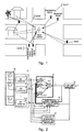
- FIG. 1 is a drawing of an example of the practical communication environment.
- FIG. 2 is a structural drawing of the smart antenna device according to the embodiment of the invention.
- FIG. 3 is a flow chart of the method according to the embodiment of the invention.
- FIG. 4 is a flow chart of wireless communication environment detection and channel identification according to FIG. 3 .
- the channel types are classified into four kinds in this embodiment: first, AWGN is the main part of the interference, the environment located in is far away from base station, signal power is weak and noise is strong; second, co-channel interference is the main part of the interference, the environment located in is interfered by co-channel from other cells, the performance of the system is affected; third, the ISI is the main part of the interference, the environment located in has severe ISI due to the great difference of time delays between each of the multipath components; fourth, there are various kinds of interferences and noises, the environment located in is complex communication environment with strong noise and both co-channel interference and ISI. Certainly, other classifications of channel types can also be used, this invention is not limited by this.
- This embodiment determines the channel types according to the eigenvalues of the correlation matrix of the signal received by the array and the in-band power spectrum deviation; the beam forming algorithms, such as Maximal Ratio Combining, Advanced Constant Modulus, Advanced Wiener, and partial multi-access interference cancellation etc. are adopted respectively in regards to the different types of channel; afterwards, corresponding multi-user detection is applied.
- the smart antenna base station has more extensive adaptability.
- FIG. 2 is the structural drawing of the smart antenna device in accordance with the embodiment of the invention, including antenna array 10 , RF channel module 11 , beam forming module 12 , channel environment detection and classification module 13 , beam forming algorithm selection and weight value generation module 14 , and multi-user detection module 15 . Since the functions of modules of scrambling generation, spread spectrum code generation, code synchronization, descrambling de-spread, clock control etc. in software radio smart antenna system are not the content that this invention focuses on, these modules will not be described in the embodiment. These modules or their output signals will be referred to directly if needed.
- Antenna array 10 is consisted of M antenna elements, i.e. 10 . 1 , 10 . 2 , . . . , 10 .M, used to receive wireless signals. Its output is connected to the input of RF channel module 11 .
- the radiation pattern of the antenna elements can be arbitrary, the arrangement of the antenna array can be arbitrary as well.
- the adaptive method of the invention will obtain the optimal array weight value under certain criterion. But in the case of different antenna arrays, the receiving quality of the optimal signal that can be reached is different.
- RF channel module 11 includes M RF channels, i.e. 11 . 1 , 11 . 2 , . . . , 11 .M, used to perform low noise amplification, automatic gain control, channel correction, baseband transfer, A/D and D/A transfer, matched filtering and so on for the signals output by M antenna elements respectively.
- the array data X is output to beam forming module 12 , channel environment detection and classification module 13 , and beam forming algorithm selection and weight value generation module 14 respectively.
- Said channel environment detection and classification module 13 further includes: an eigenvalue calculation unit, used to calculate the eigenvalue of the correlation matrix of the array data, and count the number of the effective eigenvalues; an in-band power spectrum devistion calculation unit, used to estimate the power of each channel of the signals received by the array, and calculate the in-band power spectrum deviation; and a channel type decision unit, used to identify the type that the channel belongs to currently by a set decision criterion according to the number of the effective eigenvalues and the in-band power spectrum deviation, and input the result to the beam forming algorithm selection and weight value generation module 14 .
- Said channel type is one of AWGN interference, co-channel interference, ISI, and various interferences and noises.
- the beam forming algorithm selection and weight value generation module 14 is used to select suitable beam forming algorithm according to the result of channel type output by the channel environment detection and classification module 13 , process the array data X from RF channel 11 and the feedback signal Y output by the beam forming module 12 , and calculate the new weight value W to be output to the beam forming module.
- the new weight value W [w 1 , w 2 , . . . , w M ] is made up of M components.
- the beam forming module 12 is consisted of M multipliers 12 . 1 , 12 . 2 , . . . , 12 .M and one adder 12 .A. It is used to form the beam for the array data X from RF channel module 11 and the weight value W output by the beam forming algorithm selection and weight value generation module 14 , i.e. obtain the output signal Y by multiplying and adding the array data X and weight value W.
- the multi-user detection module 15 is used to select corresponding multi-user detection algorithm according to the result of channel type output by the channel environment detection and classification module 13 , process the data Y output by the beam forming module 12 , complete distinction of users, and finally output a modulated output bit “b” to the other follow-up conventional processing modules.
- the beam forming module 12 , channel environment detection and classification module 13 , beam forming algorithm selection and weight value generation module 14 , and multi-user detection module 15 in the embodiment are realized by software in DSP. But they can also be hardware modules, that is to say, these modules can be made on specialized ASIC or FPGA.
- FIG. 2 is the flow chart of the method in accordance with the embodiment of the invention, including the following steps:
- Step 22 determining the type that the channel belongs to currently by the set decision criterion according to the eigenvalue of the correlation matrix of the signals received by the array and the in-band power spectrum deviation;
- FIG. 3 The specific flow of wireless communication environment detection and channel identification is shown in FIG. 3 , including the following steps:
- Step 33 estimating the power of each channel of the signals received by the array as P 1 , P 2 , . . . , P M ;
- Step 34 determining the effective eigenvalue, provided ⁇ N 2 is noise power, if ⁇ N 2 + ⁇ ⁇ , ⁇ is regarded as the effective eigenvalue, wherein ⁇ ⁇ is the specific parameter determined by the practical system;
- Step 35 comparing the in-band power deviation, i.e. deciding whether
- ⁇ p is satisfied, wherein i, j 1, 2, . . . M, and i ⁇ j, ⁇ p is a threshold; according to the specific parameter determined by the practical system, if it is satisfied, the power is considered to be relatively small, otherwise, the power is considered to be relatively large.
- Step 36 deciding the type that the channel belongs to currently according to the number of the effective eigenvalues and the comparison result of the in-band power deviation, the criterion is as follows:
- the co-channel interference is mainly presented, then it is the second channel type
- both the expected signals and interference signals have certain time delay expansion and angle expansion, then it is the fourth channel type.
- This invention can also adopt other suitable decision criterions, such as adopt any combination of more than two criterions selected from the above four criterions.
- the channel types shall also be re-combined accordingly.
- Step 23 selecting the corresponding adaptive algorithm according to the identification result of channel type to eliminate the interference under this kind of channel type most effectively, and calculating the uplink weight value W;
- CMA Advanced Constant Modulus Algorithm
- the embodiment adopts concatenated recursive beam forming algorithm to calculate the uplink weight value W, for which please refer to the international patent application of PCT/CN2002/000946, titled “Smart antenna and beam forming method and device”, with international publication No. WO2004/030239A1.
- the embodiment adopts pilot-bit assisted LMS_DRMTA (Least-Mean-Squares De-spread Re-spread Multi-Target Array) beam forming algorithm to calculate the uplink weight value W.
- LMS_DRMTA Least-Mean-Squares De-spread Re-spread Multi-Target Array
- Step I initializing the received weight vector of the array of i th user as [1, 0, . . . 0] T ;
- Step II updating the weight value according to the following equation (1) during pilot-bit (with its length less than or equal to 8), and generating reference signals by the following equation (2).
- ⁇ represents step length
- [X(j)] N ⁇ P represents the received vector of the array of current information bit
- [r i (j)] 1 ⁇ P is the reference signal generated by the equation (1)
- [E i (j)] 1 ⁇ P represents the correction error vector of the weight vector of the current information bit
- [Y i (j)] 1 ⁇ P is the array output of P snapshots of the current information bit
- Step IV repeating steps II-III until the algorithm converges.
- Step 25 selecting corresponding method to perform multi-user detection according to the identification result of the channel type
- the detected channel environment data is also used to select multi-user detection type, so as to eliminate the interference of this channel type most effectively.
- Minimum Mean Square based multi-user detection method is used to counteract AWGN
- the de-correlation detection method is used to counteract CCI
- a mobile station moves to the first channel type from the third channel type through the second channel type, the corresponding different methods above are adopted in real time to perform multi-user detection according to the identification result.
- the environment in which the fourth channel is located is complex communication environment, for which, this embodiment uses partial multi-access interference cancellation method to counteract various interferences and noises.
- the received weight vector of the array forms directional beam with its main lobe pointing to the place around the expected user, thereby greatly suppressing the interference user signal from other directions.
- Y i (j) is used to perform parallel interference cancellation for all active users, as a large number of interference user signal components have already been pre-suppressed, the estimation for the regeneration signal of most interference users is not very accurate, therefore, the estimation for the multi-access interference of the expected user is not very accurate either, which will even worsen the primary demodulation result of the expected user in serious case.
- the partial multi-access interference method is used so as to, on the one hand, avoid the inaccurate interference estimation due to extremely weak interference components from worsening the performance of the system, on the other hand, greatly reducing the number of interference users for practical cancellation, and decreasing the calculation amount of the system.
- array output Y i (j) is used to perform matched filtering for all active users to get primary soft decision variable for all active users:
- k th user is the expected user of this receiving channel, then it is strong interference user if
- Step 26 calculating the downlink weight value according to the obtained uplink weight value.
- uplink signal and downlink signal work at the same frequency point and pass through the same channel, and the interval between sending time and receiving time is just several millisecond, so the characteristics of the uplink and downlink channels can be regarded as constant. Therefore, the uplink weight value can be used for the downlink weight value directly, only needing to get the conjugate of the uplink weight value and multiply it with the correction weight value, as such, the user receiving space information is converted into being represented by user transmitting space.
- the transmissions of the uplink and downlink are separated through frequency, with the uplink and the downlink occupying different frequencies. Since the fast fading resulted from multipath transmission depends on the frequency, the fast fading coefficients corresponding to FDD uplink and downlink are irrelative. So the uplink weight value can not be used for the downlink weight value directly, and certain conversion is needed.
- DS-CDMA system in AWGN channel will be used as an example for description.
- the processing gain of the system is G
- N users in the sector are all far field signal sources for the base station antenna array
- E i represents the energy of each spread spectrum code-chip after the source symbol of i th user is performed spectrum spread
- b i (j) represents the value of j th source symbol of i t h user, which is +1 or ⁇ 1;
- G represents the first spread spectrum code-chip of j th source symbol of i th user
- a k ( ⁇ i ) represents k th component of the direction vector a( ⁇ i ) of the base station antenna array of i th user;
- W i [w i1 , w i2 , . . . , w iM ] T
- the array output signal of i th user is:
- Y i (j) is used to perform demodulation decision for i th user.
- Y i (j) is directly performed Matched filtering to get:
- n i (j) represents the AWGN in the receiving channel of i th user.
- the parallel interference cancellation is mainly to estimate the estimated value I i ⁇ circumflex over (() ⁇ j) of multi-access interference component in Z i (j) as exactly as possible, and subtract it from the received signal to get purer receiving signals of the expected user.
- the array pattern is also not limited to the uniform linear array, the arrays of other forms, such as non-uniform array, circle array, arc-shape array etc., can easily be generalized.
- the invention improves the limitation of application environment of one single adaptive beam forming algorithm, extends the application range of the smart antenna in communication environment, and can trace the rapid movement of users in real time, and resist various interference environments. Meanwhile, if the system architecture based on software radio is used, this invention will not need relatively large hardware cost compared with the conventional smart antenna, thereby promoting the performance-price ratio of the smart antenna system.
- the smart antenna technique advanced in the invention is a mean that can effectively overcome the characteristic of time-varying of the channel.
- the corresponding adaptive beam forming method is selected through decisions for different channels, or multi-user detection method is added, so as to satisfy the communication demands under different environments, and promote communication quality.
- the method of the present invention can be used to implement smart antenna system. It greatly promotes the performance-price ratio of smart antenna base station system with relatively low hardware cost, makes the engineering easy to implement, and greatly improves the processing performance of the smart base station.
Abstract
Description
m k,l=int[τk +l−τ l)/N]
q k,l=τk +l−τ l −N·m k,l
cf k,l =[c k,N-q
cb k,l=[0, . . . , 0,c k,0 ,c k,1 , . . . , c k,N-q
λ1≧λ2≧, . . . =λM=σN 2, wherein σN 2 is noise power.
J=E{∥w H(n)x(n)|−|α∥2}
w(n+1)=w(n)−μx(n)e*(n)
μ is the step length.
W i(j+1)=W i(j)+μX(j)E i(j+1)H. (3)
E i(j)=r i(j)−Y i(j)
only when the interference user is located near the expected user, can there be strong interference user component; the component of the interference user signal far away from the expected user is very weak. When Yi(j) is used to perform parallel interference cancellation for all active users, as a large number of interference user signal components have already been pre-suppressed, the estimation for the regeneration signal of most interference users is not very accurate, therefore, the estimation for the multi-access interference of the expected user is not very accurate either, which will even worsen the primary demodulation result of the expected user in serious case. For this reason, the partial multi-access interference method is used so as to, on the one hand, avoid the inaccurate interference estimation due to extremely weak interference components from worsening the performance of the system, on the other hand, greatly reducing the number of interference users for practical cancellation, and decreasing the calculation amount of the system.
is satisfied, and interference cancellation needs to be performed, wherein 0<ρ<1 is the pre-set threshold for distinguishing strong and weak interference user signals.
d is the spacing of the uniform linear array element, λ is carrier frequency, nk(t) represents the AWGN of kth element.
represents the output of one snapshot of the whole array. Provided the receiving weight vector of ith user is Wi=[wi1, wi2, . . . , wiM]T, then the array output signal of ith user is:
represents the multi-user interference component in the receiving channel of ith user. ni(j) represents the AWGN in the receiving channel of ith user.
Claims (22)
Applications Claiming Priority (4)
| Application Number | Priority Date | Filing Date | Title |
|---|---|---|---|
| CN200510051164 | 2005-03-02 | ||
| CN200510051164.8 | 2005-03-02 | ||
| CNB2005100511648A CN100499398C (en) | 2005-03-02 | 2005-03-02 | Method and apparatus for realizing intelligent antenna of broadband CDMA system |
| PCT/CN2005/002361 WO2006092090A1 (en) | 2005-03-02 | 2005-12-29 | A method and equipment for realizing smart antenna in wcdma system |
Publications (2)
| Publication Number | Publication Date |
|---|---|
| US20080170554A1 US20080170554A1 (en) | 2008-07-17 |
| US8064407B2 true US8064407B2 (en) | 2011-11-22 |
Family
ID=36940833
Family Applications (1)
| Application Number | Title | Priority Date | Filing Date |
|---|---|---|---|
| US11/885,595 Expired - Fee Related US8064407B2 (en) | 2005-03-02 | 2005-12-29 | Method and equipment for realizing smart antenna in WCDMA system |
Country Status (8)
| Country | Link |
|---|---|
| US (1) | US8064407B2 (en) |
| EP (1) | EP1858175B1 (en) |
| CN (1) | CN100499398C (en) |
| DK (1) | DK1858175T3 (en) |
| ES (1) | ES2389085T3 (en) |
| PL (1) | PL1858175T3 (en) |
| PT (1) | PT1858175E (en) |
| WO (1) | WO2006092090A1 (en) |
Cited By (4)
| Publication number | Priority date | Publication date | Assignee | Title |
|---|---|---|---|---|
| US20090245443A1 (en) * | 2008-03-29 | 2009-10-01 | Fujitsu Ten Limited | Diversity receiver |
| US20100232533A1 (en) * | 2008-08-25 | 2010-09-16 | Lee Daniel Chonghwan | Methods of Selecting Signal Transmitting, Receiving, and/or Sensing Devices with Probabilistic Evolutionary Algorithms in Information Conveyance Systems |
| US20110291891A1 (en) * | 2010-05-21 | 2011-12-01 | Imec | Method and system for mixed analog/digital beamforming in wireless communication systems |
| US10187110B2 (en) * | 2017-03-13 | 2019-01-22 | Kabushiki Kaisha Toshiba | Wireless communication device and wireless communication method |
Families Citing this family (23)
| Publication number | Priority date | Publication date | Assignee | Title |
|---|---|---|---|---|
| US8009578B2 (en) * | 2005-04-11 | 2011-08-30 | Panasonic Corporation | Wireless base station device, terminal, and wireless communication method |
| CN101034899B (en) * | 2007-04-29 | 2010-05-19 | 中国民航大学 | Civil aviation ground-air communication self-adaptive disturbance restraining method based on the single channel and its system |
| CN101034901B (en) * | 2007-04-29 | 2010-07-21 | 中国民航大学 | Civil aviation ground-air communication self-adaptive disturbance restraining method based on the constant mode array and its system |
| KR101320915B1 (en) * | 2007-05-10 | 2013-10-29 | 알까뗄 루슨트 | Method and apparatus for pre-processing data to be transmitted in multiple-input communication system |
| US8666004B2 (en) * | 2008-05-21 | 2014-03-04 | Qualcomm Incorporated | Methods and systems for hybrid MIMO schemes in OFDM/A systems |
| EP2221992A1 (en) * | 2009-02-19 | 2010-08-25 | Imec | Method and system for analog beamforming in wireless communication systems |
| CN101888644B (en) * | 2009-05-14 | 2014-12-10 | 中兴通讯股份有限公司 | System and method for realizing beam forming of single user |
| US8478335B2 (en) | 2011-03-23 | 2013-07-02 | United States Of America As Represented By The Secretary Of The Navy | System and method for radio communication |
| US9252908B1 (en) | 2012-04-12 | 2016-02-02 | Tarana Wireless, Inc. | Non-line of sight wireless communication system and method |
| KR102170254B1 (en) | 2013-12-10 | 2020-10-26 | 삼성전자주식회사 | Adaptive beam selection apparatus and method in a wireless communication system |
| US9379768B2 (en) * | 2014-01-31 | 2016-06-28 | Harris Corporation | Communication system with narrowband interference mitigation and related methods |
| CN104834689B (en) * | 2015-04-22 | 2019-02-01 | 上海微小卫星工程中心 | A kind of code stream type method for quickly identifying |
| CN106301514B (en) * | 2015-05-15 | 2021-01-05 | 索尼公司 | Device and method for wireless communication and communication terminal |
| CN105071841B (en) * | 2015-07-02 | 2018-03-13 | 北京理工大学 | Orthogonal code based on DS CDMA systems is the same as frequency multi-beam separation method |
| CN105007096B (en) * | 2015-07-02 | 2017-06-27 | 北京理工大学 | Nonopiate code word based on DS CDMA systems is with frequency multi-beam separation method |
| CN105099535B (en) * | 2015-07-02 | 2018-04-13 | 北京理工大学 | Multi channel signals magnitude-phase characteristics weight matrix measuring method based on DS CDMA systems |
| CN105227227B (en) * | 2015-10-15 | 2018-10-12 | 宿州学院 | A kind of intelligent antenna beam formation system and method based on small echo |
| CN106658751B (en) * | 2016-12-14 | 2020-06-02 | 北京佰才邦技术有限公司 | Channel access method and device for multi-antenna equipment |
| CN107181519B (en) * | 2017-07-10 | 2020-08-28 | 北京邮电大学 | Null steering expansion 3D-MIMO beam forming method based on moving target DOA |
| US10305555B2 (en) * | 2017-10-20 | 2019-05-28 | Micron Technology, Inc. | Autocorrelation and memory allocation for wireless communication |
| EP3725008A4 (en) | 2017-12-11 | 2021-08-04 | Telefonaktiebolaget LM Ericsson (publ) | Determination of directional beamforming weights |
| CN111985571B (en) * | 2020-08-26 | 2022-09-09 | 国网湖南省电力有限公司 | Low-voltage intelligent monitoring terminal fault prediction method, device, medium and equipment |
| CN113534198B (en) * | 2021-06-16 | 2023-05-23 | 北京遥感设备研究所 | Satellite navigation dynamic anti-interference method and system based on covariance matrix reconstruction |
Citations (2)
| Publication number | Priority date | Publication date | Assignee | Title |
|---|---|---|---|---|
| US20030201936A1 (en) | 2002-04-30 | 2003-10-30 | Lg Electronics Inc. | Adaptive beamforming apparatus and method |
| US20030216156A1 (en) * | 2002-05-17 | 2003-11-20 | Chun Byung-Jin | Apparatus and method for forming a forward link transmission beam of a smart antenna in a mobile communication system |
Family Cites Families (2)
| Publication number | Priority date | Publication date | Assignee | Title |
|---|---|---|---|---|
| CN1160890C (en) * | 2000-11-15 | 2004-08-04 | 华为技术有限公司 | Digital wave beam forming method and module in radio communication system and its array receiver |
| CN1486106A (en) | 2002-09-24 | 2004-03-31 | 深圳市中兴通讯股份有限公司 | Apparatus and method for selfadaptive beam forming of intelligent antenna |
-
2005
- 2005-03-02 CN CNB2005100511648A patent/CN100499398C/en active Active
- 2005-12-29 PT PT05824066T patent/PT1858175E/en unknown
- 2005-12-29 ES ES05824066T patent/ES2389085T3/en active Active
- 2005-12-29 US US11/885,595 patent/US8064407B2/en not_active Expired - Fee Related
- 2005-12-29 EP EP05824066A patent/EP1858175B1/en not_active Not-in-force
- 2005-12-29 WO PCT/CN2005/002361 patent/WO2006092090A1/en not_active Application Discontinuation
- 2005-12-29 PL PL05824066T patent/PL1858175T3/en unknown
- 2005-12-29 DK DK05824066.4T patent/DK1858175T3/en active
Patent Citations (3)
| Publication number | Priority date | Publication date | Assignee | Title |
|---|---|---|---|---|
| US20030201936A1 (en) | 2002-04-30 | 2003-10-30 | Lg Electronics Inc. | Adaptive beamforming apparatus and method |
| US6937189B2 (en) * | 2002-04-30 | 2005-08-30 | Lg Electronics Inc. | Adaptive beamforming apparatus and method |
| US20030216156A1 (en) * | 2002-05-17 | 2003-11-20 | Chun Byung-Jin | Apparatus and method for forming a forward link transmission beam of a smart antenna in a mobile communication system |
Non-Patent Citations (4)
| Title |
|---|
| International Search Report. Dated Nov. 18, 2009. |
| Kamiya et al. "A Software Antenna: Reconfigurable Adaptive Arrays Based on Eigenvalue Decomposition", IEICE Trans. Commun., vol. E82-B, No. 12, Dec. 1999. |
| Karasawa et al, "Algorithm Diversity in Software Antenna", IEICE Trans. Commun., Jun. 2000. * |
| Karasawa et al. "Algorithm Diversity in a Software Antenna" IEICE Trans. Commun., vol. E83-B, No. 6, Jun. 2000. |
Cited By (6)
| Publication number | Priority date | Publication date | Assignee | Title |
|---|---|---|---|---|
| US20090245443A1 (en) * | 2008-03-29 | 2009-10-01 | Fujitsu Ten Limited | Diversity receiver |
| US20100232533A1 (en) * | 2008-08-25 | 2010-09-16 | Lee Daniel Chonghwan | Methods of Selecting Signal Transmitting, Receiving, and/or Sensing Devices with Probabilistic Evolutionary Algorithms in Information Conveyance Systems |
| US8457240B2 (en) * | 2008-08-25 | 2013-06-04 | Daniel Lee | Methods of selecting signal transmitting, receiving, and/or sensing devices with probabilistic evolutionary algorithms in information conveyance systems |
| US20110291891A1 (en) * | 2010-05-21 | 2011-12-01 | Imec | Method and system for mixed analog/digital beamforming in wireless communication systems |
| US8619886B2 (en) * | 2010-05-21 | 2013-12-31 | Imec | Method and system for mixed analog/digital beamforming in wireless communication systems |
| US10187110B2 (en) * | 2017-03-13 | 2019-01-22 | Kabushiki Kaisha Toshiba | Wireless communication device and wireless communication method |
Also Published As
| Publication number | Publication date |
|---|---|
| EP1858175A4 (en) | 2009-12-16 |
| EP1858175B1 (en) | 2012-06-06 |
| CN1829119A (en) | 2006-09-06 |
| PT1858175E (en) | 2012-09-06 |
| EP1858175A1 (en) | 2007-11-21 |
| CN100499398C (en) | 2009-06-10 |
| ES2389085T3 (en) | 2012-10-23 |
| WO2006092090A1 (en) | 2006-09-08 |
| US20080170554A1 (en) | 2008-07-17 |
| DK1858175T3 (en) | 2012-08-27 |
| PL1858175T3 (en) | 2012-11-30 |
Similar Documents
| Publication | Publication Date | Title |
|---|---|---|
| US8064407B2 (en) | Method and equipment for realizing smart antenna in WCDMA system | |
| EP1540763B1 (en) | Antenna array including virtual antenna elements and method | |
| Choi et al. | A novel adaptive beamforming algorithm for a smart antenna system in a CDMA mobile communication environment | |
| JP3872953B2 (en) | Wireless communication device using adaptive antenna | |
| KR100735813B1 (en) | Method of generating weighted vector in the development of smart antennas for IMT-2000 CDMA wireless communication | |
| KR101089031B1 (en) | A method of realizing smart antenna based on software radio and system therefor | |
| US7047044B2 (en) | Radio receiving device and radio receiving method | |
| US8022860B1 (en) | Enchanced interference cancellation and telemetry reception in multipath environments with a single paraboic dish antenna using a focal plane array | |
| US20070189362A1 (en) | Method and system for channel estimation, related receiver and computer program product | |
| US7006042B2 (en) | Antenna array system, method of controlling the directivity pattern thereof, and mobile terminal | |
| JP2004509534A (en) | Smart antenna without phase calibration for CDMA reverse link | |
| US7565172B2 (en) | Adaptive antenna reception method and device | |
| Hossain et al. | Adaptive beamforming algorithms for smart antenna systems | |
| Tarighat et al. | Performance analysis of different algorithms for cdma2000 antenna array system and a new multi user beamforming (MUB) algorithm | |
| Ogawa et al. | Spatial-domain path-diversity using an adaptive array for mobile communications | |
| WO2005002067A2 (en) | Multi-carrier spread spectrum using non-linear modification of sub-carrier bands | |
| Fukawa | A suboptimal receiver for joint spatial-temporal filtering and multiuser detection in mobile radio communications | |
| Walke et al. | Joint detection and joint pre-distortion techniques for SD/TD/CDMA systems | |
| Mohamed et al. | A simple combined conjugate gradient beamforming and interference cancellation scheme for DS-CDMA in a multipath fading channel | |
| Rani et al. | MUSIC and LMS algorithms for a smart antenna system | |
| Van Rooyen et al. | Smart Antenna Techniques | |
| Fares et al. | Efficient sequential blind beamforming for wireless underground communications | |
| Marques et al. | Channel estimation with array processing for the uplink of UMTS-TDD | |
| Mizusawa et al. | Spatial-Temporal Signal Processing for Broadband Wireless Systems | |
| Montalbano et al. | Spatio-temporal array processing for aperiodic CDMA downlink transmission |
Legal Events
| Date | Code | Title | Description |
|---|---|---|---|
| AS | Assignment |
Owner name: ZTE CORPORATION, CHINA Free format text: ASSIGNMENT OF ASSIGNORS INTEREST;ASSIGNORS:WANG, YANWEN;ZHANG, LI;CHEN, DONGLI;REEL/FRAME:019839/0188 Effective date: 20070827 |
|
| ZAAA | Notice of allowance and fees due |
Free format text: ORIGINAL CODE: NOA |
|
| ZAAB | Notice of allowance mailed |
Free format text: ORIGINAL CODE: MN/=. |
|
| STCF | Information on status: patent grant |
Free format text: PATENTED CASE |
|
| FPAY | Fee payment |
Year of fee payment: 4 |
|
| MAFP | Maintenance fee payment |
Free format text: PAYMENT OF MAINTENANCE FEE, 8TH YEAR, LARGE ENTITY (ORIGINAL EVENT CODE: M1552); ENTITY STATUS OF PATENT OWNER: LARGE ENTITY Year of fee payment: 8 |
|
| FEPP | Fee payment procedure |
Free format text: MAINTENANCE FEE REMINDER MAILED (ORIGINAL EVENT CODE: REM.); ENTITY STATUS OF PATENT OWNER: LARGE ENTITY |
|
| LAPS | Lapse for failure to pay maintenance fees |
Free format text: PATENT EXPIRED FOR FAILURE TO PAY MAINTENANCE FEES (ORIGINAL EVENT CODE: EXP.); ENTITY STATUS OF PATENT OWNER: LARGE ENTITY |
|
| STCH | Information on status: patent discontinuation |
Free format text: PATENT EXPIRED DUE TO NONPAYMENT OF MAINTENANCE FEES UNDER 37 CFR 1.362 |
|
| FP | Lapsed due to failure to pay maintenance fee |
Effective date: 20231122 |