US8073016B2 - Apparatus and method for channel coding and multiplexing in CDMA communication system - Google Patents
Apparatus and method for channel coding and multiplexing in CDMA communication system Download PDFInfo
- Publication number
- US8073016B2 US8073016B2 US12/107,524 US10752408A US8073016B2 US 8073016 B2 US8073016 B2 US 8073016B2 US 10752408 A US10752408 A US 10752408A US 8073016 B2 US8073016 B2 US 8073016B2
- Authority
- US
- United States
- Prior art keywords
- frame
- frames
- radio frame
- radio
- channel
- Prior art date
- Legal status (The legal status is an assumption and is not a legal conclusion. Google has not performed a legal analysis and makes no representation as to the accuracy of the status listed.)
- Expired - Fee Related, expires
Links
- 238000000034 method Methods 0.000 title claims abstract description 37
- 238000004891 communication Methods 0.000 title claims abstract description 26
- 239000000945 filler Substances 0.000 claims description 63
- 239000002131 composite material Substances 0.000 claims 2
- 230000005540 biological transmission Effects 0.000 abstract description 16
- 230000011218 segmentation Effects 0.000 description 27
- 239000000872 buffer Substances 0.000 description 9
- 238000010586 diagram Methods 0.000 description 6
- 208000037918 transfusion-transmitted disease Diseases 0.000 description 6
- 238000003780 insertion Methods 0.000 description 5
- 230000037431 insertion Effects 0.000 description 5
- 238000005562 fading Methods 0.000 description 4
- 230000008569 process Effects 0.000 description 4
- 230000006870 function Effects 0.000 description 3
- 238000010295 mobile communication Methods 0.000 description 3
- 230000008859 change Effects 0.000 description 1
- 238000010276 construction Methods 0.000 description 1
- 230000003247 decreasing effect Effects 0.000 description 1
- 230000000694 effects Effects 0.000 description 1
- 238000012986 modification Methods 0.000 description 1
- 230000004048 modification Effects 0.000 description 1
Images


Classifications
-
- H—ELECTRICITY
- H04—ELECTRIC COMMUNICATION TECHNIQUE
- H04B—TRANSMISSION
- H04B7/00—Radio transmission systems, i.e. using radiation field
- H04B7/14—Relay systems
- H04B7/15—Active relay systems
- H04B7/204—Multiple access
- H04B7/216—Code division or spread-spectrum multiple access [CDMA, SSMA]
-
- H—ELECTRICITY
- H04—ELECTRIC COMMUNICATION TECHNIQUE
- H04L—TRANSMISSION OF DIGITAL INFORMATION, e.g. TELEGRAPHIC COMMUNICATION
- H04L1/00—Arrangements for detecting or preventing errors in the information received
- H04L1/004—Arrangements for detecting or preventing errors in the information received by using forward error control
- H04L1/0056—Systems characterized by the type of code used
- H04L1/0067—Rate matching
- H04L1/0068—Rate matching by puncturing
-
- H—ELECTRICITY
- H04—ELECTRIC COMMUNICATION TECHNIQUE
- H04B—TRANSMISSION
- H04B1/00—Details of transmission systems, not covered by a single one of groups H04B3/00 - H04B13/00; Details of transmission systems not characterised by the medium used for transmission
- H04B1/69—Spread spectrum techniques
- H04B1/707—Spread spectrum techniques using direct sequence modulation
-
- H—ELECTRICITY
- H04—ELECTRIC COMMUNICATION TECHNIQUE
- H04J—MULTIPLEX COMMUNICATION
- H04J13/00—Code division multiplex systems
-
- H—ELECTRICITY
- H04—ELECTRIC COMMUNICATION TECHNIQUE
- H04L—TRANSMISSION OF DIGITAL INFORMATION, e.g. TELEGRAPHIC COMMUNICATION
- H04L1/00—Arrangements for detecting or preventing errors in the information received
- H04L1/0001—Systems modifying transmission characteristics according to link quality, e.g. power backoff
- H04L1/0015—Systems modifying transmission characteristics according to link quality, e.g. power backoff characterised by the adaptation strategy
- H04L1/0017—Systems modifying transmission characteristics according to link quality, e.g. power backoff characterised by the adaptation strategy where the mode-switching is based on Quality of Service requirement
-
- H—ELECTRICITY
- H04—ELECTRIC COMMUNICATION TECHNIQUE
- H04L—TRANSMISSION OF DIGITAL INFORMATION, e.g. TELEGRAPHIC COMMUNICATION
- H04L1/00—Arrangements for detecting or preventing errors in the information received
- H04L1/004—Arrangements for detecting or preventing errors in the information received by using forward error control
- H04L1/0041—Arrangements at the transmitter end
-
- H—ELECTRICITY
- H04—ELECTRIC COMMUNICATION TECHNIQUE
- H04L—TRANSMISSION OF DIGITAL INFORMATION, e.g. TELEGRAPHIC COMMUNICATION
- H04L1/00—Arrangements for detecting or preventing errors in the information received
- H04L1/0078—Avoidance of errors by organising the transmitted data in a format specifically designed to deal with errors, e.g. location
- H04L1/0083—Formatting with frames or packets; Protocol or part of protocol for error control
-
- H—ELECTRICITY
- H04—ELECTRIC COMMUNICATION TECHNIQUE
- H04L—TRANSMISSION OF DIGITAL INFORMATION, e.g. TELEGRAPHIC COMMUNICATION
- H04L25/00—Baseband systems
- H04L25/02—Details ; arrangements for supplying electrical power along data transmission lines
- H04L25/14—Channel dividing arrangements, i.e. in which a single bit stream is divided between several baseband channels and reassembled at the receiver
-
- H—ELECTRICITY
- H04—ELECTRIC COMMUNICATION TECHNIQUE
- H04L—TRANSMISSION OF DIGITAL INFORMATION, e.g. TELEGRAPHIC COMMUNICATION
- H04L1/00—Arrangements for detecting or preventing errors in the information received
- H04L1/004—Arrangements for detecting or preventing errors in the information received by using forward error control
- H04L1/0056—Systems characterized by the type of code used
- H04L1/0071—Use of interleaving
-
- H—ELECTRICITY
- H04—ELECTRIC COMMUNICATION TECHNIQUE
- H04L—TRANSMISSION OF DIGITAL INFORMATION, e.g. TELEGRAPHIC COMMUNICATION
- H04L1/00—Arrangements for detecting or preventing errors in the information received
- H04L1/08—Arrangements for detecting or preventing errors in the information received by repeating transmission, e.g. Verdan system
Definitions
- the present invention relates generally to a channel communication apparatus and method in a mobile communication system, and in particular, to a channel coding and multiplexing apparatus and method in which multi-transport channel frames are converted to multi-physical channel frames.
- a conventional CDMA (Code Division Multiple Access) mobile communication system primarily provides a voice service.
- the future CDMA mobile communication system will support the IMT-2000 standard, which can provide a high-speed data service as well as the voice service. More specifically, the IMT-2000 standard can provide a high-quality voice service, a moving picture service, an Internet browsing service, etc.
- This future CDMA communication system will be comprised of a downlink for transmitting data from a base station to a mobile station and an uplink for transmitting data from the mobile station to the base station.
- an object of the present invention to provide a channel coding and multiplexing apparatus and method in which a transport channel frame data is segmented into plurality of radio frames in a transmitting device of a CDMA communication system.
- TTI radio frame transmission time interval
- a channel coding and multiplexing apparatus and method in a CDMA communication system has as many radio frame matchers as transport channels and a multiplexer.
- Each radio frame matcher has a radio frame segmenter and segments a transport channel frame that may have a different transmission time interval from the transmission time intervals of other transport channel frames in other transport channels to form radio frames and the multiplexer multiplexes the radio frames to a serial data frame.
- FIG. 1 is a block diagram of an embodiment of an uplink channel transmitting device according to the present invention
- FIG. 2 is a block diagram of an embodiment of a downlink channel transmitting device according to the present invention.
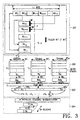
- FIG. 3 is a view illustrating the operation of the channel transmitting devices shown in FIGS. 1 and 2 ;
- FIG. 4 is a block diagram of an embodiment of a channel receiving device according to the present invention.
- FIG. 5 is a flowchart illustrating a radio frame generation procedure using filler bits according to the present invention
- FIG. 6 is a flowchart illustrating a radio frame generation procedure without using filler bits according to the present invention
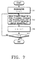
- FIG. 7 is a flowchart illustrating an embodiment of a radio frame multiplexing procedure according to the present invention.
- FIG. 8 is a flowchart illustrating an embodiment of a physical channel frame generation procedure according to the present invention.
- the present invention defines in detail radio frame segmentation, multiplexing, and physical channel segmentation for channel coding & multiplexing in a channel communication device of a CDMA communication system. That is, radio frame segmentation, multiplexing of radio frames, and segmentation of the multiplexed radio frames into physical channel frames, that are not provided by the 3GPP Technical Specification for Multiplexing and Channel Coding, TS 25.212 version 1.0.0 1999. 05. 05, will be defined fully enough to deal with bit-basis operations.
- the 3GPP Technical Specification for Multiplexing Channel Coding, TS 25.212 version 1.0.0 1999. 05. 05 published by 3GPP Organizational Partners is hereby incorporated by reference.
- Transport channel frame or “input data frame”: a data frame applied to the input of a radio frame matcher from a channel coder;
- Radio frame a data frame formed by segmenting the input transport channel frame, where the size of the radio frame is a function of the transmission time interval (TTI) of the input transport channel frame and the radio frame TTI as explained below.
- TTI transmission time interval
- a transport channel frame may be transmitted at a different data rate for a different TTI.
- FIGS. 1 and 2 are block diagrams of uplink and downlink channel transmitting devices, respectively, according to an embodiment of the present invention. Receiving devices for receiving information from the channel transmitting devices have the reverse configurations of their counterparts.
- FIG. 3 is a view referred to for describing the operations of the channel transmitting devices shown in FIGS. 1 and 2 .
- Radio frame matchers 101 , 102 , . . . 10 N receive the data frames of the corresponding transport channels, segment the received data frames into data of a size, which is a function of the transport channel frame TTI and the radio frame TTIs (i.e., radio frames), and sequentially output the segmented radio frames (The “N” is used throughout in the reference number notation to indicate an indefinite number of respective components).
- Each of the radio frame matchers 101 to 10 N includes an interleaver for compensating for fading, a radio frame segmenter for segmenting an interleaved transport channel frame into radio frames, and a rate matcher for controlling the data rate of the radio frames by puncturing/repeating certain parts of the radio frames.
- a corresponding radio frame matcher inserts a filler bit into the transport channel frame, which is performed in its radio frame segmenter by way of example in the embodiment of the present invention.
- a multiplexer 200 sequentially multiplexes radio frames sequentially received from the radio frame matchers 101 to 10 N to a serial data stream.
- a physical channel segmenter 300 segments the serial data stream received from the multiplexer 200 into data frames as many as the number of physical channels using at least two codes and transfers the data frames to the corresponding physical channels, so that the serial data frame can be transmitted on the physical channels.
- the physical channel segmenter 300 does not need to segment the serial data stream, but instead transmits the serial data stream on a physical channel.
- reference numeral 100 denotes the entire block of channel coding & multiplexing chains having the radio frame matchers 101 to 10 N for receiving N encoded data that may have different qualities of service (QoS) in parallel.
- QoS qualities of service
- data streams applied to the radio frame matchers 101 to 10 N from MAC (Medium Access Control) and higher layers (transport block/transport block set) may have different QoS.
- transport channel frames may have different data rates and different TTIs and each radio frame matcher receives frame data from a corresponding channel coder.
- the same coder outputs frame data of the same QoS during each service.
- the QoS of the same coder may change to another QoS. Therefore, data of different QoS may be applied to the radio frame matchers 101 to 10 N, but each radio frame matcher receives frame data of the same QoS during each individual service.
- Each radio frame matcher receives encoded frame data having a different data frame size and a frame transmission period according to its QoS from a corresponding channel coder.
- QoS is determined by voice, data, and images. Accordingly, the data rate and TTI of frame data depend on its QoS.
- data frames have TTIs of 10, 20, 40, or 80 msec.
- input coded data may have a different data rate and a different TTI. In other words, frames of each channel have a unique TTI and data rate.
- encoded data generated from one channel coder is processed and in the case where data of two channels is to be transmitted, encoded data generated from two corresponding channel coders are processed.
- Each of first interleavers 111 to 11 N primarily interleaves a transport channel frame received from a corresponding channel coder.
- a channel frame received from each channel coder may have a different TTI and a different data rate.
- a transport channel frame length in bits may not be an integer multiple of the radio frame length in bits.
- it is preferable to insert a filler bit into the transport channel frame to make the transport channel frame length in bits as long as a multiple of the radio frame length in bits. That is, if L i /T i (L i : the length of an input transport channel frame in the i th transport channel and in certain embodiments of the present invention, T i TTI for i th transport channel/10 msec) is not an integer, a filler bit is inserted. The filler bit is pre-processed prior to radio frame segmentation in order to maintain a radio frame length constant for a transmission period.
- Radio frame segmenters 121 to 12 N sequentially segment input transport channel frames into 10-msec radio frames RF 1 to RF N as indicated by reference numeral 302 in FIG. 3 .
- the rate matchers 131 to 13 N adjust the data rates of the radio frames RF 1 to RF N received from the radio frame segmenters 121 to 12 N, respectively, and output data frames KF 1 to KF N , respectively K i refers to the length of the respective KF i frames.
- the above radio frame matchers 101 to 10 N receive corresponding transport channel frames in parallel, check the sizes of the transport channel frames, segment the transport channel frames into radio frames, and output the radio frames in parallel.
- the multiplexer 200 multiplexes the data frames KF 1 to KF N received from the rate matchers 131 to 13 N to a serial data stream of size P as indicated by reference numeral 303 in FIG. 3 .
- the multiplexer 200 can sequentially multiplex the data frames KF 1 to KF N .
- the size of the multiplexed frame P K 1 +K 2 + . . . +K N .
- the multiplexer 200 first determines the number N of transport channels, receives radio frames in parallel from the radio frame matchers 101 to 10 N, and sequentially multiplexes the radio frames to a serial data frame. That is, the multiplexer 200 outputs a serial data frame indicated by 303 in FIG. 3 .
- a physical channel segmenter 300 segments the multiplexed frame of size P received from the multiplexer 200 into M physical channel frames as indicated by 304 in FIG. 3 (M is the number of available physical channels) and feeds the physical channel frames to second interleavers 401 to 40 N.
- M is the number of available physical channels
- each physical channel frame is as long as P/M.
- the physical channels may use multiple codes.
- the physical channel segmenter 300 sets the number M of available physical channels, segments the multiplexed serial data frame into M physical channel frames, and assigns them to the corresponding physical channels.
- the multiplexed serial data frame can be segmented into one or more physical channel radio frames of the same data rate. Alternatively, the multiplexed serial data frame can be segmented into one or more physical channel frames of different data rates.
- An uplink channel receiving device for receiving radio frames from the uplink channel transmitting device shown in FIG. 1 performs the operation of the uplink channel transmitting device in the reverse order.
- the uplink channel receiving device will be described later with reference to FIG. 4 .
- FIG. 3 The operation of each component shown in FIG. 1 is illustrated in FIG. 3 in detail.
- reference numeral 301 denotes segmentation of transport channel frames received in parallel from the first interleavers 111 to 11 N into radio frames which will be transmitted from the radio frame segmenters 121 to 12 N. If L i /T i is not an integer, a corresponding radio frame segmenter inserts a filler bit to make L i be a multiple of T i . As shown in FIG. 3 , filler bits are sequentially inserted into radio frames, preferably beginning with the last radio frame.
- the reference numeral 301 in FIG. 3 illustrates the procedure for adding filler bits to the radio frames. The procedure is explained in detail in the subsequent sections. The embodiment of the present invention is described in the context with the case that one filler bit 0 or 1 is inserted into one radio frame.
- Reference numeral 302 indicates rate matching of the radio frames according to their data rates.
- Reference numeral 304 indicates segmentation of the multiplexed frame into M physical channel frames and parallel assignment of the M physical channel frames to physical channels.
- FIG. 2 is a block diagram of a downlink channel transmitting device for downlink channel coding & multiplexing, illustrating radio frame matchers 151 to 15 N through second interleavers 800 .
- the downlink channel transmitting device operates in the same manner as the uplink channel transmitting device shown in FIGS. 1 and 3 except that the outputs of radio frame segmenters 171 to 17 N are applied to the input of the multiplexer 600 .
- Rate matchers are not shown in the drawing because they are disposed before the first interleavers in the downlink channel transmitting device of FIG. 2 .
- a downlink channel receiving device is the same in operation as the uplink channel receiving device except that it does not perform rate dematching.
- radio frame segmenters are labeled with 121 to 12 N, the multiplexer with 200 , and the physical channel segmenter with 300 .
- Uplink and downlink radio frame segmenters operate in the same manner.
- the radio frame segmenters 121 to 12 N segment input transport channel frames into 10-msec radio frame blocks and sequentially output the radio frames.
- filler bits may or may not be inserted into a transport channel frame according to the bit number of the transport channel frame.
- insertion of filler bits is implemented in the radio frame segmenters 121 to 12 N if filler bits are inserted.
- One filler bit is inserted into one radio frame and filler bit insertion begins with the last radio frame.
- a description of inserting a filler bit into a transport channel frame and then segmenting the transport channel frame into radio frames in the radio frame segmenters 121 to 12 N referring to FIG. 5 will precede that of segmenting a transport channel frame into radio frames without inserting filler bits in the radio frame segmenters 121 to 12 N referring to FIG. 6 .
- the number r i of filler bits is calculated in the following way in order to make L i /T i an integer. Since T i ranges from 0 to 8, r i ranges from 0 to 7. (L i +r i )/T i achieved with the use of filler bits is defined as KD i and R i , respectively for the downlink and the uplink.
- a filler bit is added to the last bit position of each of corresponding radio frames from a (T i ⁇ r i +1) th radio frame in order to maintain a frame length constant, i.e., KD i or R i . 0 or 1 is arbitrarily selected as a filler bit.
- the filler bit has little to do with performance and serves as a reserved bit that can be selected by a system user. It can be contemplated that the filler bit is designated as a discontinuous transmission (DTX) bit so that a transmitter does not transmit the filler bit after channel coding & multiplexing.
- DTX discontinuous transmission
- the radio frame segmenter 12 i is included in a transmitting device and its counterpart is a radio frame desegmenter in a receiving device.
- Radio frame desegmentation is equivalent to the reverse operation of radio frame segmentation in that 10-msec blocks received for a transmission period are sequentially arranged and assembled into one frame.
- FIG. 5 illustrates a radio frame generation process using filler bits in the above-described manner. Variables as used below will first be defined.
- RF i,t a t th 10 msec radio frame in an i th radio frame matcher
- L i input frame size from the i th radio frame matcher.
- the radio frame segmenter checks whether the number r i of filler bits is 0. If the number r i of filler bits is 0, the radio frame segmenter reads data of a radio frame size from an input frame and stores it in step 517 . On the other hand, if the number r i of filler bits is not 0, the radio frame segmenter checks whether a frame index t is (Ti ⁇ r i +1) in step 515 , that is, a current radio frame is to be added with a filler bit. In the case of a radio frame that will not be added with a filler bit, the radio frame segmenter reads data of a radio frame size from an input frame and stores it in step 519 and proceeds to step 525 .
- the radio frame segmenter In the case of a radio frame that will be added with a filler bit, the radio frame segmenter reads data one bit smaller than a radio frame size from the input frame and stores it in step 521 .
- the radio frame segmenter inserts the last bit position of the stored radio frame in step 523 , increases the frame index t by 1 in step 525 , and checks whether the updated frame index t is larger than the segment number T i corresponding to the radio frame TTI in step 527 . If the frame index t is smaller than the segment number T i corresponding to the radio frame TTI, the radio frame segmenter returns to step 513 . If the frame index t is larger than the segment number T i corresponding to the radio frame TTI, the radio frame generation procedure ends. Radio frames generated in this manner are sequentially fed to the second multiplexer 200 .
- a radio frame segmenter that does not use filler bits may be used instead of the above described radio frame segmenter.
- T i ranges from 0 to 8
- r i ranges from 0 to 7.
- (L i +r i )/T i for the downlink and the uplink are defined as KD i and R i , respectively.
- T i TTI (msec) of the i th transport channel/10 (msec) ⁇ ⁇ 1, 2, 4, 8 ⁇ .
- the size of the first to (T i ⁇ r i ) th radio frames is R i and the size of the (T i ⁇ r i +1) th to the last radio frames is (R i ⁇ 1).
- the size of the first to (TD i ⁇ rD i ) th radio frames is KD i and the size of the (TD i ⁇ rD i +1) th to the last radio frames is (KD i ⁇ 1).
- Radio frame blocks of sizes varied with time are fed to the multiplexer.
- a frame size in the multiplexer may vary at every 10 msec intervals and the physical channel segmenter may also operate differently at every 10 msec intervals, making control of frame size complicated. Accordingly, it is preferable to employ a radio frame segmenter which inserts filler bits.
- the radio frame segmenter 12 i is included in a transmitting device and its counterpart is a radio frame desegmenter in a receiving device.
- Radio frame desegmentation is equivalent to the reverse operation of radio frame segmentation in that 10-msec blocks received for a transmission period are sequentially arranged and assembled into one frame.
- FIG. 6 illustrates a radio frame generation process without inserting filler bits in the above-described manner. Variables as used hereinbelow will first be defined.
- RF i,t a t th 10 msec radio frame in an i th channel coding & multiplexing chain
- L i input frame size from the i th channel coding & multiplexing chain.
- the radio frame segmenter checks whether the number ri of filler bits is 0. If the number r i of filler bits is 0, the radio frame segmenter reads data of a radio frame size from an input frame and stores it in step 617 . On the other hand, if the number ri of filler bits is not 0, the radio frame segmenter checks whether a frame index t is (T i ⁇ r i +1) in step 615 . If the frame index t is smaller than (T i ⁇ r i +1), the radio frame segmenter reads data of a radio frame size from an input frame and stores it in step 619 and proceeds to step 623 .
- the radio frame segmenter reads data one bit smaller than a radio frame size from the input frame and stores it in step 621 .
- the radio frame segmenter increases the frame index t by 1 in step 623 , and checks whether the updated frame index t is larger than the segment number T i corresponding to the radio frame TTI in step 625 . If the frame index t is smaller than the segment number T i corresponding to the radio frame TTI, the radio frame segmenter returns to step 613 . If the frame index t is greater than the segment number T i corresponding to the radio frame TTI, the radio frame generation procedure ends. Radio frames generated in this manner are sequentially fed to the multiplexer 200 .
- the multiplexer 200 for the uplink will be described. Bits as described below are applied to the input of the multiplexer 200 .
- Bits as described below are applied to the input of the multiplexer 200 .
- the multiplexer 200 is included in a transmitting device and its counterpart is a demultiplexer in a receiving device.
- the demultiplexer reversely performs the operation of the multiplexer 200 , that is, segments an input frame into N blocks and feeds the N blocks to corresponding radio frame dematchers.
- FIG. 7 is a flowchart illustrating a radio frame multiplexing procedure in the multiplexer 200 . Prior to description of the procedure shown in FIG. 7 , terms as used below are defined.
- N total number of radio frame matchers
- radio frame matcher index (1, 2, . . . , N);
- RFi a 10 msec radio frame in an i th radio frame matcher.
- the multiplexer 200 sets the radio frame matcher index i to an initial value 1 in step 711 and stores a radio frame received from the i th radio frame matcher in a multiplexing buffer in step 713 .
- the multiplexer 200 increases the radio frame matcher index i by 1.
- the multiplexer 200 checks whether the increased index i is greater than the total number N of radio frame matchers in step 717 . If i is equal to or smaller than N, the multiplexer 200 returns to step 713 . If i is greater than N, the multiplexer 200 ends the multiplexing procedure. As described above, the multiplexer 200 sequentially stores radio frames received from the radio frame matchers in the multiplexing buffer and generates a multiplexed frame of size P that is a serial data frame.
- the physical channel frame segmenter 300 operates in the same manner for the uplink and the downlink.
- the above physical channel segmentation scheme in the physical channel segmenter is advantageous in that the best use of the effects of the second interleavers are made. Therefore, the probability of bit errors after decoding at a receiver, caused by burst error on a fading channel, can be minimized.
- a data rate of 1 ⁇ 3 for a general channel coder three symbols represent one information bit.
- a receiver may have a lower bit error rate (BER) in the present invention than the above-described physical channel segmentation.
- BER bit error rate
- the physical channel frame segmenter is included in a transmitting device and its counterpart is a physical channel desegmenter in a receiving device.
- the physical channel desegmenter performs the reverse operation of the physical channel segmenter, that is, sequentially arranges M physical channel frames and assembles them into one frame.
- FIG. 8 is a flowchart illustrating a physical channel frame generating procedure in the physical channel segmenter. Terms as used below will first be defined.
- m physical channel index (1, 2, . . . , M);
- P index data block size in bits.
- the physical channel segmenter 300 sets the physical channel index m to an initial value 1 in step 811 and reads a data block of size P/M from input data of size P and stores it in an m th physical channel buffer in step 813 . Then, the physical channel segmenter 300 increases the physical channel index m by 1 in step 815 and checks whether the increased physical channel index m is greater than the total number M of the physical channels in step 817 . If m is equal to or smaller than M, the physical channel segmenter 300 returns to step 813 . On the contrary, if m is greater than M, the physical channel segmentation ends.
- FIG. 4 is a block diagram of a channel receiving device having the counterparts of the radio frame segmenter, the multiplexer, and the physical channel segmenter as described above.
- a physical channel memory 411 stores second-interleaved symbols.
- a first address generator 412 generates a write address for every M bits of the second-interleaved symbols at which the M bits will be stored in the physical channel memory 411 .
- a second address generator 413 generates a read address for sequentially reading the symbols from the physical channel memory 411 when the symbols are completely stored in the physical channel memory 411 .
- a demultiplexer 414 distributes symbols received from the physical channel memory 411 to N buffers 415 to 4 N 5 .
- the buffers 415 to 4 N 5 feed the stored symbols to corresponding radio desegmenters 417 to 4 N 7 without rate dematching if the symbols are for the downlink and to rate dematchers 416 to 4 N 6 if the symbols are for the uplink.
- the rate dematchers 416 to 4 N 6 perform zero symbol insertion and symbol combination, in the reverse order of rate matching.
- the radio frame desegmenters 417 to 4 N 7 assemble the symbols received from the rate dematchers 416 to 4 N 6 to data of corresponding transport channel TTIs and transmit the desegmented data to a channel decoder for channel decoding.
- the first address generator 412 operates to write every M bits in the physical channel memory 411 , that is a buffer memory for storing symbols received after second deinterleaving. Therefore, the physical channel memory 411 receives a total of P symbols from the second interleaver by operating P/M times. When there is no data on each channel coding & multiplexing channel, the total number of received symbols is smaller than P. Hence, a maximum buffer size is P.
- the demultiplexer 414 serves to distinguish N symbols.
- the classified symbols are transmitted directly to the radio frame desegmenters 417 to 4 N 7 without rate dematching if they are the downlink ones, whereas the symbols are subjected to rate dematching if they are the uplink ones. That is, the rate dematchers 416 to 4 N 6 implements zero symbol insertion and symbol combination, which is the reverse operation of rate matching.
- the radio frame desegmenters 417 to 4 N 7 transmit desegmented symbols to corresponding channel decoders for channel decoding.
- the operation of the receiving device is basically the reverse of that of the transmitting device.
- radio frame segmentation, multiplexing, and physical channel segmentation for multiplexing & channel coding are defined in detail.
- Frames of various types generated from channel coders are converted to radio frames, multiplexed, and converted to physical frames.
- the physical frames are then assigned to physical channels. Therefore, uplink and downlink transmitting devices in a CDMA communication system can implement various communication services such as transmission of voice, data, and images.
Abstract
Description
r i =T i−(L i mod T i), here r i={0, 1, 2, 3, 4, 5, 6, 7}
downlink: KD i=(LD i +rD i)/TD i
LDi, rDi and TDi are Li, ri and Ti for the downlink, respectively
uplink: R i=(L i +r i)/T i
- output bits of the radio frame segmenter for the first 10 msec: t=1
c i,j =b i,j , j=1, 2, . . . , (L i +r i)/T i - output bits of the radio frame segmenter for the second 10 msec: t=2
c i,j =b i,(j+(Li+ri)/Ti)) , j=1, 2, . . . , (L i +r i)/T i - output bits of the radio frame segmenter for the (Ti−ri)th 10 msec: t=(Ti−ri)
c i,j =b i,(j+(Ti−ri−1)(Li+ri)/Ti)) , j=1, 2, . . . , (L i +r i)/T i - output bits of the radio frame segmenter for the (Ti−ri+1)th 10 msec: t=(Ti−ri+1)
c i,j =b i,(j+(Ti−ri)(Li+ri)/Ti)) , j=1, 2, . . . , (L i +r i−1)/T i
c i,j=filler_bit(0/1), j=(L i +r i)/T i - output bits of the radio frame segmenter for the
T i th 10 msec: t=Ti
c i,j =b i,(j+(Ti−ri)(Li+ri)/Ti)) , j=1, 2, . . . , (L i +r i−1)/T i
c i,j=filler_bit(0/1), j=(L i +r i)/T i
t:=1/*frame time index initialization*/
r i :=T i −L i mod Ti/*number of filler bits*/
R i:=(L i +r i)/T i for UL (uplink)/*radio frame size for uplink*/
KD i:=(LD i +rD i)/TD i for DL (downlink)/*radio frame size for downlink*/
r i =T i−(L i mod T i), here r i={(0, 1, 2, 3, 4, 5, 6, 7}
downlink: KD i=(LD i +rD i)/TD i
uplink: R i=(L i +r i)/T i
- output bits of the radio frame segmenter for the first 10 msec: t=1
c i,j =b i,j , j=1, 2, . . . , (L i +r i)/T i - output bits of the radio frame segmenter for the second 10 msec: t=2
c i,j =b i,(j+(Li+ri)/Ti)) , j=1, 2, . . . , (L i +r i)/T i - output bits of the radio frame segmenter for the (Ti−ri)th 10 msec: t=(Ti−ri)
c i,j =b i,(j+(Ti−ri−1)(Li+ri)/Ti)) , j=1, 2, . . . , (L i +r i)/T i - output bits of the radio frame segmenter for the (Ti−ri+1)th 10 msec: t=(Ti−ri+1)
c i,j =b i,(j+(Ti−ri)(Li+ri)/Ti)) , j=1, 2, . . . , (L i +r i)/T i - output bits of the radio frame segmenter for the
T 1 th 10 msec: t=Ti
c i,j =b i,(j+(Ti−ri)(Li+ri)/Ti)) , j=1, 2, . . . , (L i +r i)/T i
t:=1/*frame time index initialization*/
ri:=T i −L mod T i/*number of filler bits*/
R i:=(L i +r i)/T i for UL (uplink)/*radio frame size for uplink*/
KD i:=(LD i +rD i)/TD i for DL (downlink)/*radio frame size for downlink*/
- output bits of rate matcher #1: c1,1, c1,2, . . . , c1,K1
- output bits of rate matcher #2: c2,1, c2,2, . . . , c2,K2
- output bits of rate matcher #3: c3,1, c3,2, . . . , c3,K3
- . . .
- output bits of rate matcher #N: cN,1, cN,2, . . . , cN,KN
when j=1, 2, 3, . . . ,P(P=K 1 +K 2 + . . . +K N),
d j =c i,j j=1, 2, . . . , K 1
d j =c 2,(j−K1) j=K 1+1, K 1+2, . . . , K 1 +K 2
d j =c 3,(j−(K1+K2)) j=(K 1 +K 2)+1, (K 1 +K 2)+2, . . . , (K 1 +K 2)+K 3
. . .
d j =c N,(j−(K1+K2+ . . . +KN−1)) j=(K 1 +K 2 + . . . +K N−1)+1, (K 1 +K 2 + . . . +K N−1)+2, . . . , (K 1 +K 2 + . . . +K N−1)+K N
- output bits of the physical channel frame segmenter for physical channel #1:
e 1,j =d j j=1,2, . . . , P/M - output bits of the physical channel frame segmenter for physical channel #2:
e 2,j =d (j+P/M) j=1,2, . . . , P/M - output bits of the physical channel frame segmenter for physical channel #M:
e M,j =d (j+(M−1)P/M) j=1,2, . . . , P/M
- Bits before physical channel segmentation:
- Bits after physical channel segmentation:
- Bits before physical channel segmentation:
- Bits after physical channel segmentation:
Claims (15)
d j =c i,j for j=1, 2, . . . , K 1,
d j =c 2,(j−K1) for j=K 1+1, K 1+2, . . . , K 1 +K 2,
d j =c 3,(j−(K1+K2)) for j=(K 1 +K 2)+1, (K 1 +K 2)+2, . . . , (K 1 +K 2)+K 3
. . .
d j =c N,(j−(K1+K2+ . . . +KN−1)) for j=(K 1 +K 2 + . . . +K N−1)+1, (K 1 +K 2 + . . . +K N−1)+2, . . . , (K 1 +K 2 + . . . +K N−1)+K N.
Priority Applications (1)
| Application Number | Priority Date | Filing Date | Title |
|---|---|---|---|
| US12/107,524 US8073016B2 (en) | 1999-06-25 | 2008-04-22 | Apparatus and method for channel coding and multiplexing in CDMA communication system |
Applications Claiming Priority (6)
| Application Number | Priority Date | Filing Date | Title |
|---|---|---|---|
| KR1999-26221 | 1999-06-25 | ||
| KR19990026221 | 1999-06-25 | ||
| KR19990027163 | 1999-07-07 | ||
| KR1999-27163 | 1999-07-07 | ||
| US09/603,062 US7386001B1 (en) | 1999-06-25 | 2000-06-26 | Apparatus and method for channel coding and multiplexing in CDMA communication system |
| US12/107,524 US8073016B2 (en) | 1999-06-25 | 2008-04-22 | Apparatus and method for channel coding and multiplexing in CDMA communication system |
Related Parent Applications (1)
| Application Number | Title | Priority Date | Filing Date |
|---|---|---|---|
| US09/603,062 Continuation US7386001B1 (en) | 1999-06-25 | 2000-06-26 | Apparatus and method for channel coding and multiplexing in CDMA communication system |
Publications (2)
| Publication Number | Publication Date |
|---|---|
| US20080198792A1 US20080198792A1 (en) | 2008-08-21 |
| US8073016B2 true US8073016B2 (en) | 2011-12-06 |
Family
ID=36973916
Family Applications (2)
| Application Number | Title | Priority Date | Filing Date |
|---|---|---|---|
| US09/603,062 Active 2024-05-10 US7386001B1 (en) | 1999-06-25 | 2000-06-26 | Apparatus and method for channel coding and multiplexing in CDMA communication system |
| US12/107,524 Expired - Fee Related US8073016B2 (en) | 1999-06-25 | 2008-04-22 | Apparatus and method for channel coding and multiplexing in CDMA communication system |
Family Applications Before (1)
| Application Number | Title | Priority Date | Filing Date |
|---|---|---|---|
| US09/603,062 Active 2024-05-10 US7386001B1 (en) | 1999-06-25 | 2000-06-26 | Apparatus and method for channel coding and multiplexing in CDMA communication system |
Country Status (19)
| Country | Link |
|---|---|
| US (2) | US7386001B1 (en) |
| EP (6) | EP1108307B1 (en) |
| JP (5) | JP3599704B2 (en) |
| KR (1) | KR100383602B1 (en) |
| CN (1) | CN1314222C (en) |
| AT (6) | ATE338383T1 (en) |
| AU (1) | AU759491B2 (en) |
| BR (1) | BR0006859B1 (en) |
| CA (1) | CA2340254C (en) |
| CY (5) | CY1105184T1 (en) |
| DE (7) | DE60030171T3 (en) |
| DK (6) | DK1108307T3 (en) |
| ES (6) | ES2269879T3 (en) |
| ID (1) | ID27858A (en) |
| IL (1) | IL141461A0 (en) |
| PL (6) | PL202729B1 (en) |
| PT (6) | PT1357672E (en) |
| RU (1) | RU2208297C2 (en) |
| WO (1) | WO2001001626A1 (en) |
Families Citing this family (45)
| Publication number | Priority date | Publication date | Assignee | Title |
|---|---|---|---|---|
| ES2269879T3 (en) † | 1999-06-25 | 2007-04-01 | Samsung Electronics Co., Ltd. | APPARATUS AND METHOD FOR CODING AND MULTIPLEXING OF CHANNEL, IN A CDMA COMMUNICATION SYSTEM. |
| KR100434264B1 (en) * | 1999-09-21 | 2004-06-04 | 엘지전자 주식회사 | parameter determinating Method for downlink rate matching |
| FR2799320B1 (en) * | 1999-10-04 | 2002-05-17 | Mitsubishi Electric France | FLOW BALANCING PROCESS BETWEEN CORRESPONDING DATA TRANSPORT CHANNELS, DEVICE, BASE STATION AND MOBILE STATION |
| KR100407937B1 (en) * | 1999-10-07 | 2003-12-01 | 엘지전자 주식회사 | parameter determinating Method for downlink rate matching |
| SG158743A1 (en) | 2000-01-14 | 2010-02-26 | Interdigital Tech Corp | Wireless communication system with selectively sized data transport blocks |
| KR100703106B1 (en) * | 2000-05-16 | 2007-04-05 | 유티스타콤코리아 유한회사 | Apparatus and method for transmitting data information in parallel with data |
| KR20010113233A (en) * | 2000-06-17 | 2001-12-28 | 강상훈 | Method and system for high speed wireless communication |
| US6909722B1 (en) * | 2000-07-07 | 2005-06-21 | Qualcomm, Incorporated | Method and apparatus for proportionately multiplexing data streams onto one data stream |
| KR100525433B1 (en) * | 2000-12-30 | 2005-11-02 | 엘지전자 주식회사 | Apparatus for coding channel in Time Division Duplex Mode |
| DE10101703A1 (en) * | 2001-01-15 | 2002-07-18 | Philips Corp Intellectual Pty | Wireless network has transport channel with time interval of at least one radio frame active if transmission time interval start/radio frame coincide, forming transport-format combination(s) |
| JP3920220B2 (en) * | 2001-01-31 | 2007-05-30 | 三菱電機株式会社 | Communication device |
| KR100753309B1 (en) * | 2001-04-10 | 2007-08-29 | 주식회사 팬택앤큐리텔 | Modulator for 2nd interleaving in 3GPP asynchronous system |
| KR100377626B1 (en) * | 2001-05-16 | 2003-03-26 | 엘지전자 주식회사 | Method for assigning function block and slot to emboding DEMUX/MUX in in mobile system |
| FR2834152B1 (en) * | 2001-12-26 | 2004-04-30 | Nortel Networks Ltd | PROCESS FOR PROCESSING DIGITAL SYMBOLS IN A COMMUNICATION SYSTEM AND SENDER AND RECEIVER FOR IMPLEMENTING THE PROCESS |
| US7296243B2 (en) | 2002-03-19 | 2007-11-13 | Aol Llc | Animating display motion |
| US7505478B2 (en) | 2002-10-02 | 2009-03-17 | Marvell International Ltd. | Method and apparatus of de-multiplexing data |
| US7269783B2 (en) * | 2003-04-30 | 2007-09-11 | Lucent Technologies Inc. | Method and apparatus for dedicated hardware and software split implementation of rate matching and de-matching |
| KR100575925B1 (en) * | 2003-12-04 | 2006-05-02 | 삼성전자주식회사 | Rate Matching Method and Apparatus for Multiplexing Channels with Different Transmission Time Intervals in Communication Systems |
| US8582596B2 (en) | 2004-06-04 | 2013-11-12 | Qualcomm Incorporated | Coding and modulation for broadcast and multicast services in a wireless communication system |
| US8233431B2 (en) * | 2004-08-13 | 2012-07-31 | Nokia Corporation | WCDMA uplink HARQ operation during the reconfiguration of the TTI length |
| CN100426919C (en) * | 2004-11-12 | 2008-10-15 | 中兴通讯股份有限公司 | Method for configuring transmission channel and coding combined transmission channel mapping relation |
| KR100606370B1 (en) * | 2004-11-30 | 2006-07-31 | 엘지노텔 주식회사 | Method for error detection of scheduling information in 3GPP system |
| US9014152B2 (en) | 2008-06-09 | 2015-04-21 | Qualcomm Incorporated | Increasing capacity in wireless communications |
| US9071344B2 (en) | 2005-08-22 | 2015-06-30 | Qualcomm Incorporated | Reverse link interference cancellation |
| US8611305B2 (en) | 2005-08-22 | 2013-12-17 | Qualcomm Incorporated | Interference cancellation for wireless communications |
| JP2007157287A (en) * | 2005-12-07 | 2007-06-21 | Matsushita Electric Ind Co Ltd | Semiconductor storage device |
| KR100842537B1 (en) * | 2006-01-18 | 2008-07-01 | 삼성전자주식회사 | Apparatus and Method Processing input-output data in Communication System |
| US8780771B2 (en) | 2007-02-06 | 2014-07-15 | Qualcomm Incorporated | Cyclic delay diversity and precoding for wireless communication |
| US8509710B2 (en) | 2007-02-06 | 2013-08-13 | Qualcomm Incorporated | MIMO transmission with explicit and implicit cyclic delays |
| WO2008105771A1 (en) * | 2007-03-01 | 2008-09-04 | Thomson Licensing | A method and apparatus for selecting an access point or relay node in a multi-hop wireless network |
| ATE510441T1 (en) * | 2007-08-09 | 2011-06-15 | Nokia Siemens Networks Oy | MOBILE COMMUNICATION TERMINAL, COMMUNICATION STATION, COMMUNICATION NETWORK AND COMMUNICATION METHOD |
| US7898443B2 (en) * | 2007-12-05 | 2011-03-01 | Qualcomm Incorporated | Apparatus and methods using a linear memory model for encoder output buffers |
| US7903562B2 (en) * | 2008-02-05 | 2011-03-08 | Lockheed Martin Corporation | Method and system for congestion control |
| EP2150001B1 (en) | 2008-08-01 | 2019-10-23 | Telefonaktiebolaget LM Ericsson (publ) | Technique for rate matching in a data transmission system |
| US9237515B2 (en) | 2008-08-01 | 2016-01-12 | Qualcomm Incorporated | Successive detection and cancellation for cell pilot detection |
| US9277487B2 (en) | 2008-08-01 | 2016-03-01 | Qualcomm Incorporated | Cell detection with interference cancellation |
| US9160577B2 (en) | 2009-04-30 | 2015-10-13 | Qualcomm Incorporated | Hybrid SAIC receiver |
| CN102668628B (en) * | 2009-11-27 | 2015-02-11 | 高通股份有限公司 | Method and device for increasing capacity in wireless communications |
| KR101376676B1 (en) | 2009-11-27 | 2014-03-20 | 퀄컴 인코포레이티드 | Increasing capacity in wireless communications |
| CN101754024B (en) * | 2009-12-16 | 2012-01-11 | 中兴通讯股份有限公司 | Multiplexing device and multiplexing method |
| US8340126B2 (en) | 2010-06-07 | 2012-12-25 | Lockheed Martin Corporation | Method and apparatus for congestion control |
| US9686008B2 (en) * | 2013-03-15 | 2017-06-20 | Orbital Sciences Corporation | Protection of commercial communications |
| KR101463775B1 (en) | 2013-05-06 | 2014-11-24 | 한국전자통신연구원 | Multi-frame data processing apparatus using frame disassembling and method thereof |
| WO2018056213A1 (en) | 2016-09-23 | 2018-03-29 | 三菱電機株式会社 | Power semiconductor module and power semiconductor device |
| US11905638B2 (en) | 2019-11-22 | 2024-02-20 | Whirlpool Corporation | Laundry treating appliance for drying laundry |
Citations (26)
| Publication number | Priority date | Publication date | Assignee | Title |
|---|---|---|---|---|
| US4679191A (en) | 1983-05-04 | 1987-07-07 | Cxc Corporation | Variable bandwidth switching system |
| US4930139A (en) | 1989-05-31 | 1990-05-29 | O'neill Communications, Inc. | Spread spectrum communication system |
| US4987570A (en) | 1989-02-09 | 1991-01-22 | Data General Corporation | Methods and apparatus for performing time interleaved multiplexed rate adaptation for sub-rate channels in a digital data communication system |
| SU1653167A1 (en) | 1988-01-26 | 1991-05-30 | Ленинградский электротехнический институт им.В.И.Ульянова (Ленина) | Device for binary data reception |
| JPH0685808A (en) | 1992-09-02 | 1994-03-25 | Nec Corp | Frame synchronization system |
| JPH06350593A (en) | 1993-06-08 | 1994-12-22 | Nec Corp | Frame synchronization device |
| US5537410A (en) | 1994-09-15 | 1996-07-16 | Oki Telecom | Subsequent frame variable data rate indication method |
| WO1997000568A1 (en) | 1995-06-14 | 1997-01-03 | International Business Machines Corporation | Packet data transmission in code-division multiple access communication systems |
| US5729526A (en) | 1995-10-31 | 1998-03-17 | Fujitsu Limited | Asynchronous transfer mode type multimedia radiocommunication system |
| US5831978A (en) | 1996-10-18 | 1998-11-03 | Telefonaktiebolaget L M Ericsson Publ. | Method for multiplexing of parallel information streams in a CDMA system |
| KR19990009537A (en) | 1997-07-10 | 1999-02-05 | 양승택 | CDA channel structure for packet service |
| WO1999016264A1 (en) | 1997-09-24 | 1999-04-01 | Telefonaktiebolaget Lm Ericsson (Publ) | Multi-service handling by a single mobile station |
| KR20000040263A (en) | 1998-12-17 | 2000-07-05 | 강상훈 | Method for composing physical channel frame of wide band mobile multimedia wireless transmission system |
| EP1045521A2 (en) | 1999-04-13 | 2000-10-18 | Nortel Networks Limited | Rate matching and channel interleaving for a communications system |
| WO2000062465A1 (en) | 1999-04-12 | 2000-10-19 | Telefonaktiebolaget Lm Ericsson (Publ) | Communications system and method for matching and balancing the bit rates of transport channels to the bit rate of a physical channel |
| US6201798B1 (en) * | 1997-11-14 | 2001-03-13 | Worldspace Management Corporation | Signaling protocol for satellite direct radio broadcast system |
| US6269126B1 (en) | 1998-03-27 | 2001-07-31 | Nokia Networks Oy | Data communication and radio system |
| EP1156616A2 (en) | 1999-04-21 | 2001-11-21 | Mitsubishi Electric Telecom Europe | Method for balancing the ratio Eb/I in a service multiplexing CDMA system and telecommunication system using this method |
| US6381234B2 (en) | 1996-11-08 | 2002-04-30 | Sony Corporation | Communication method, base station and terminal apparatus |
| US6397367B1 (en) | 1998-06-05 | 2002-05-28 | Samsung Electronics, Co., Ltd. | Device and methods for channel coding and rate matching in a communication system |
| US6493666B2 (en) | 1998-09-29 | 2002-12-10 | William M. Wiese, Jr. | System and method for processing data from and for multiple channels |
| US6567392B1 (en) | 1999-09-24 | 2003-05-20 | Koninklijke Philips Electronics N.V. | Method and system for using vocorder rate determination for high quality CDMA voice transmission |
| US6768728B1 (en) | 1998-03-14 | 2004-07-27 | Samsung Electronics Co., Ltd. | Device and method for exchanging frame messages of different lengths in CDMA communication system |
| US6795506B1 (en) | 1999-10-05 | 2004-09-21 | Cisco Technology, Inc. | Methods and apparatus for efficient scheduling and multiplexing |
| US6868075B1 (en) | 1999-09-28 | 2005-03-15 | Telefonaktiebolaget Lm Ericsson (Publ) | Method and apparatus for compressed mode communications over a radio interface |
| US20110194571A1 (en) * | 1995-06-30 | 2011-08-11 | Interdigital Technology Corporation | Adaptive forward power control and adaptive reverse power control for spread-spectrum communications |
Family Cites Families (8)
| Publication number | Priority date | Publication date | Assignee | Title |
|---|---|---|---|---|
| US5442625A (en) * | 1994-05-13 | 1995-08-15 | At&T Ipm Corp | Code division multiple access system providing variable data rate access to a user |
| KR970008949B1 (en) * | 1994-11-16 | 1997-06-03 | Korea Electronics Telecomm | Method and system for providing a frequency handoff in communication in a cdma cellular telephone system |
| US5537398A (en) * | 1995-05-12 | 1996-07-16 | Motorola, Inc. | Apparatus for multi-rate simulcast communications |
| JPH1051354A (en) * | 1996-05-30 | 1998-02-20 | N T T Ido Tsushinmo Kk | Ds-cdma transmission method |
| JPH09327072A (en) * | 1996-06-05 | 1997-12-16 | Hitachi Ltd | Cdma communication method and spread spectrum communication system |
| US6064663A (en) * | 1996-09-10 | 2000-05-16 | Nokia Mobile Phones Limited | Cellular CDMA data link utilizing multiplexed channels for data rate increase |
| KR100454930B1 (en) * | 1998-08-17 | 2005-01-13 | 삼성전자주식회사 | Apparatus and method for multiplexing physical channel in cdma communication system |
| ES2269879T3 (en) † | 1999-06-25 | 2007-04-01 | Samsung Electronics Co., Ltd. | APPARATUS AND METHOD FOR CODING AND MULTIPLEXING OF CHANNEL, IN A CDMA COMMUNICATION SYSTEM. |
-
2000
- 2000-06-26 ES ES03016891T patent/ES2269879T3/en not_active Expired - Lifetime
- 2000-06-26 PL PL383899A patent/PL202729B1/en unknown
- 2000-06-26 EP EP20000940975 patent/EP1108307B1/en not_active Expired - Lifetime
- 2000-06-26 EP EP20030016893 patent/EP1357674B2/en not_active Expired - Lifetime
- 2000-06-26 DE DE2000630171 patent/DE60030171T3/en not_active Expired - Lifetime
- 2000-06-26 DE DE2000609843 patent/DE60009843T2/en not_active Expired - Lifetime
- 2000-06-26 PL PL383896A patent/PL202727B1/en unknown
- 2000-06-26 JP JP2001506182A patent/JP3599704B2/en not_active Expired - Lifetime
- 2000-06-26 BR BRPI0006859-4B1A patent/BR0006859B1/en not_active IP Right Cessation
- 2000-06-26 PT PT03016891T patent/PT1357672E/en unknown
- 2000-06-26 PL PL383895A patent/PL202726B1/en unknown
- 2000-06-26 ES ES03016894T patent/ES2268235T5/en not_active Expired - Lifetime
- 2000-06-26 AT AT03016892T patent/ATE338383T1/en active
- 2000-06-26 WO PCT/KR2000/000668 patent/WO2001001626A1/en active IP Right Grant
- 2000-06-26 DK DK00940975T patent/DK1108307T3/en active
- 2000-06-26 DE DE2000630336 patent/DE60030336T3/en not_active Expired - Lifetime
- 2000-06-26 PL PL346341A patent/PL198409B1/en unknown
- 2000-06-26 RU RU2001105192A patent/RU2208297C2/en active
- 2000-06-26 AU AU55754/00A patent/AU759491B2/en not_active Expired
- 2000-06-26 PT PT03016894T patent/PT1357675E/en unknown
- 2000-06-26 DE DE2000630490 patent/DE60030490T2/en not_active Expired - Lifetime
- 2000-06-26 PT PT03016892T patent/PT1357673E/en unknown
- 2000-06-26 DE DE2000630492 patent/DE60030492T2/en not_active Expired - Lifetime
- 2000-06-26 DE DE2000630491 patent/DE60030491T2/en not_active Expired - Lifetime
- 2000-06-26 PT PT03016895T patent/PT1357676E/en unknown
- 2000-06-26 KR KR10-2000-0035454A patent/KR100383602B1/en active IP Right Grant
- 2000-06-26 PT PT00940975T patent/PT1108307E/en unknown
- 2000-06-26 DK DK03016892T patent/DK1357673T3/en active
- 2000-06-26 ES ES00940975T patent/ES2219354T3/en not_active Expired - Lifetime
- 2000-06-26 CN CNB008011605A patent/CN1314222C/en not_active Expired - Lifetime
- 2000-06-26 DK DK03016891T patent/DK1357672T3/en active
- 2000-06-26 EP EP20030016891 patent/EP1357672B1/en not_active Expired - Lifetime
- 2000-06-26 PT PT03016893T patent/PT1357674E/en unknown
- 2000-06-26 AT AT03016895T patent/ATE338384T1/en active
- 2000-06-26 DK DK03016895T patent/DK1357676T3/en active
- 2000-06-26 DE DE2000223176 patent/DE20023176U1/en not_active Expired - Lifetime
- 2000-06-26 ES ES03016895T patent/ES2269881T3/en not_active Expired - Lifetime
- 2000-06-26 AT AT00940975T patent/ATE264574T1/en active
- 2000-06-26 AT AT03016894T patent/ATE337645T1/en active
- 2000-06-26 EP EP20030016892 patent/EP1357673B1/en not_active Expired - Lifetime
- 2000-06-26 ES ES03016893T patent/ES2268234T5/en not_active Expired - Lifetime
- 2000-06-26 IL IL14146100A patent/IL141461A0/en active IP Right Grant
- 2000-06-26 ES ES03016892T patent/ES2269880T3/en not_active Expired - Lifetime
- 2000-06-26 US US09/603,062 patent/US7386001B1/en active Active
- 2000-06-26 PL PL383897A patent/PL201440B1/en unknown
- 2000-06-26 EP EP20030016894 patent/EP1357675B2/en not_active Expired - Lifetime
- 2000-06-26 CA CA002340254A patent/CA2340254C/en not_active Expired - Lifetime
- 2000-06-26 DK DK03016894T patent/DK1357675T4/en active
- 2000-06-26 AT AT03016893T patent/ATE336830T1/en active
- 2000-06-26 EP EP20030016895 patent/EP1357676B1/en not_active Expired - Lifetime
- 2000-06-26 DK DK03016893T patent/DK1357674T4/en active
- 2000-06-26 AT AT03016891T patent/ATE338382T1/en active
- 2000-06-26 PL PL383898A patent/PL202728B1/en unknown
- 2000-06-26 ID ID20010363A patent/ID27858A/en unknown
-
2003
- 2003-10-29 JP JP2003369459A patent/JP3836463B2/en not_active Expired - Lifetime
- 2003-10-29 JP JP2003369460A patent/JP4327557B2/en not_active Expired - Lifetime
- 2003-10-29 JP JP2003369458A patent/JP3836462B2/en not_active Expired - Lifetime
- 2003-10-29 JP JP2003369457A patent/JP3863137B2/en not_active Expired - Lifetime
-
2006
- 2006-08-30 CY CY20061101222T patent/CY1105184T1/en unknown
- 2006-08-30 CY CY20061101221T patent/CY1105183T1/en unknown
- 2006-09-26 CY CY20061101390T patent/CY1105383T1/en unknown
- 2006-09-26 CY CY20061101388T patent/CY1105378T1/en unknown
- 2006-09-26 CY CY20061101389T patent/CY1105382T1/en unknown
-
2008
- 2008-04-22 US US12/107,524 patent/US8073016B2/en not_active Expired - Fee Related
Patent Citations (27)
| Publication number | Priority date | Publication date | Assignee | Title |
|---|---|---|---|---|
| US4679191A (en) | 1983-05-04 | 1987-07-07 | Cxc Corporation | Variable bandwidth switching system |
| SU1653167A1 (en) | 1988-01-26 | 1991-05-30 | Ленинградский электротехнический институт им.В.И.Ульянова (Ленина) | Device for binary data reception |
| US4987570A (en) | 1989-02-09 | 1991-01-22 | Data General Corporation | Methods and apparatus for performing time interleaved multiplexed rate adaptation for sub-rate channels in a digital data communication system |
| US4930139A (en) | 1989-05-31 | 1990-05-29 | O'neill Communications, Inc. | Spread spectrum communication system |
| JPH0685808A (en) | 1992-09-02 | 1994-03-25 | Nec Corp | Frame synchronization system |
| JPH06350593A (en) | 1993-06-08 | 1994-12-22 | Nec Corp | Frame synchronization device |
| US5537410A (en) | 1994-09-15 | 1996-07-16 | Oki Telecom | Subsequent frame variable data rate indication method |
| WO1997000568A1 (en) | 1995-06-14 | 1997-01-03 | International Business Machines Corporation | Packet data transmission in code-division multiple access communication systems |
| US20110194571A1 (en) * | 1995-06-30 | 2011-08-11 | Interdigital Technology Corporation | Adaptive forward power control and adaptive reverse power control for spread-spectrum communications |
| US5729526A (en) | 1995-10-31 | 1998-03-17 | Fujitsu Limited | Asynchronous transfer mode type multimedia radiocommunication system |
| US5831978A (en) | 1996-10-18 | 1998-11-03 | Telefonaktiebolaget L M Ericsson Publ. | Method for multiplexing of parallel information streams in a CDMA system |
| US6381234B2 (en) | 1996-11-08 | 2002-04-30 | Sony Corporation | Communication method, base station and terminal apparatus |
| KR19990009537A (en) | 1997-07-10 | 1999-02-05 | 양승택 | CDA channel structure for packet service |
| WO1999016264A1 (en) | 1997-09-24 | 1999-04-01 | Telefonaktiebolaget Lm Ericsson (Publ) | Multi-service handling by a single mobile station |
| US6201798B1 (en) * | 1997-11-14 | 2001-03-13 | Worldspace Management Corporation | Signaling protocol for satellite direct radio broadcast system |
| US6768728B1 (en) | 1998-03-14 | 2004-07-27 | Samsung Electronics Co., Ltd. | Device and method for exchanging frame messages of different lengths in CDMA communication system |
| US6269126B1 (en) | 1998-03-27 | 2001-07-31 | Nokia Networks Oy | Data communication and radio system |
| US6397367B1 (en) | 1998-06-05 | 2002-05-28 | Samsung Electronics, Co., Ltd. | Device and methods for channel coding and rate matching in a communication system |
| US6493666B2 (en) | 1998-09-29 | 2002-12-10 | William M. Wiese, Jr. | System and method for processing data from and for multiple channels |
| KR20000040263A (en) | 1998-12-17 | 2000-07-05 | 강상훈 | Method for composing physical channel frame of wide band mobile multimedia wireless transmission system |
| WO2000062465A1 (en) | 1999-04-12 | 2000-10-19 | Telefonaktiebolaget Lm Ericsson (Publ) | Communications system and method for matching and balancing the bit rates of transport channels to the bit rate of a physical channel |
| EP1045521A2 (en) | 1999-04-13 | 2000-10-18 | Nortel Networks Limited | Rate matching and channel interleaving for a communications system |
| EP1156616A2 (en) | 1999-04-21 | 2001-11-21 | Mitsubishi Electric Telecom Europe | Method for balancing the ratio Eb/I in a service multiplexing CDMA system and telecommunication system using this method |
| US6501748B1 (en) | 1999-04-21 | 2002-12-31 | Mitsubishi Electric Telecom Europe | Method for balancing the ratio Eb/I in a service multiplexing CDMA system and telecommunication systems using same |
| US6567392B1 (en) | 1999-09-24 | 2003-05-20 | Koninklijke Philips Electronics N.V. | Method and system for using vocorder rate determination for high quality CDMA voice transmission |
| US6868075B1 (en) | 1999-09-28 | 2005-03-15 | Telefonaktiebolaget Lm Ericsson (Publ) | Method and apparatus for compressed mode communications over a radio interface |
| US6795506B1 (en) | 1999-10-05 | 2004-09-21 | Cisco Technology, Inc. | Methods and apparatus for efficient scheduling and multiplexing |
Non-Patent Citations (17)
| Title |
|---|
| "Adaptive Use of Parallel Serial Links"; IBM Technical Disclosure Bulletin; vol. 39 No. 6; Jun. 1996; pp. 2. |
| Alfred Baier et al.; "Design Study for a CDMA-Based Third-Generation Mobile Radio System"; IEEE Journal on Selected Areas in Communications; vol. 12; No. 4; May 1994. |
| Chih-I et al.; "Performance of Multi-Code CDMA Wireless Personal Communications Networks"; 1995 IEEE; pp. 907-911. |
| European Search Report dated May 3, 2002 issued in EP Appln. No. 00940975.6. |
| European Search Report dated Nov. 7, 2003 issued in a counterpart application, namely, Appln. No. EP03016891. |
| Gang Wu et al.; "An Integrated Transmission Protocol for Broadband Mobile Multimedia Communication Systems"; Mar. 1997; pp. 1346-1350. |
| Japanese Office Action dated Jan. 6, 2004 issued in a counterpart application, name Appln. No. 2001-506182. |
| Mitsubishi Electric: "Discussion on Segmentation of Block Between Radio Frame for TrCH with Transmission Time Interval Longer than 10ms"; RAN WG1 Meeting #4; Apr. 19-20, 1999. |
| Notice of Opposition to a European Patent; European Patent No. 1,357,674; May 2007; pp. 26. |
| Notice of Opposition to a European Patent; European Patent No. 1,357,675; May 2007; pp. 27. |
| Technical Specification 3GPP TS 25.212 Version 1.0.0; Apr. 1999; pp. 38. |
| Technical Specification 3GPP TS 25.212 Version 2.0.0; Jun. 1999; pp. 38. |
| TS 25.212: "3rd Generation Partnership Project (3GPP); Technical Specification Group (TSG) Radio Access Network (RAN); Working Group 1 (WG1); Multiplexing and Channel Coding (FDD)"; Apr. 1999. |
| TSGR1 #4 (99) 349; "Discussion on Segmentation of Block Between Radio Frame for TrCH with Transmission Time Interval Longer Than 10ms"; Apr. 1999; pp. 6. |
| TSG-RAN Working Group 1 (Radio) Meeting #3; "S1.12 (V1.1.0): Multiplexing and Channel Coding (FEE)"; Mar. 22-26, 1999. |
| Vol. 3 Specifications of Air-Interface for 3G Mobile System Version 1.0; Dec. 1997; pp. 173. |
| Yukihiko Okumura; WG1 Proposal relating to radio frame segmentation; 3GPP-TSG-RAN-WG1 Archives; Apr. 1999; pp. 11. |
Also Published As
Similar Documents
| Publication | Publication Date | Title |
|---|---|---|
| US8073016B2 (en) | Apparatus and method for channel coding and multiplexing in CDMA communication system | |
| EP1389369A4 (en) | Physical layer processing for a wireless communication system using code division multiple access | |
| US20050123005A1 (en) | Rate matching method and apparatus for multiplexing channels having different transmission time intervals in a mobile communcation system | |
| KR100364583B1 (en) | Apparatus and method for repeating and transmitting of memoryless error correction channel coded signal | |
| ZA200101530B (en) | Apparatus and method for channel coding and multiplexing in CDMA communication system. |
Legal Events
| Date | Code | Title | Description |
|---|---|---|---|
| ZAAA | Notice of allowance and fees due |
Free format text: ORIGINAL CODE: NOA |
|
| ZAAB | Notice of allowance mailed |
Free format text: ORIGINAL CODE: MN/=. |
|
| STCF | Information on status: patent grant |
Free format text: PATENTED CASE |
|
| FEPP | Fee payment procedure |
Free format text: PAYOR NUMBER ASSIGNED (ORIGINAL EVENT CODE: ASPN); ENTITY STATUS OF PATENT OWNER: LARGE ENTITY |
|
| FPAY | Fee payment |
Year of fee payment: 4 |
|
| MAFP | Maintenance fee payment |
Free format text: PAYMENT OF MAINTENANCE FEE, 8TH YEAR, LARGE ENTITY (ORIGINAL EVENT CODE: M1552); ENTITY STATUS OF PATENT OWNER: LARGE ENTITY Year of fee payment: 8 |
|
| FEPP | Fee payment procedure |
Free format text: MAINTENANCE FEE REMINDER MAILED (ORIGINAL EVENT CODE: REM.); ENTITY STATUS OF PATENT OWNER: LARGE ENTITY |
|
| LAPS | Lapse for failure to pay maintenance fees |
Free format text: PATENT EXPIRED FOR FAILURE TO PAY MAINTENANCE FEES (ORIGINAL EVENT CODE: EXP.); ENTITY STATUS OF PATENT OWNER: LARGE ENTITY |
|
| STCH | Information on status: patent discontinuation |
Free format text: PATENT EXPIRED DUE TO NONPAYMENT OF MAINTENANCE FEES UNDER 37 CFR 1.362 |
|
| FP | Lapsed due to failure to pay maintenance fee |
Effective date: 20231206 |