US8073199B2 - Method for minimizing scintillation in dynamic images - Google Patents
Method for minimizing scintillation in dynamic images Download PDFInfo
- Publication number
- US8073199B2 US8073199B2 US12/130,294 US13029408A US8073199B2 US 8073199 B2 US8073199 B2 US 8073199B2 US 13029408 A US13029408 A US 13029408A US 8073199 B2 US8073199 B2 US 8073199B2
- Authority
- US
- United States
- Prior art keywords
- images
- image
- averaged
- instructions
- data processor
- Prior art date
- Legal status (The legal status is an assumption and is not a legal conclusion. Google has not performed a legal analysis and makes no representation as to the accuracy of the status listed.)
- Active, expires
Links
- 238000000034 method Methods 0.000 title claims description 41
- 239000002131 composite material Substances 0.000 claims abstract description 20
- 238000012935 Averaging Methods 0.000 claims abstract description 17
- 230000000873 masking effect Effects 0.000 claims abstract description 7
- 238000012545 processing Methods 0.000 claims description 35
- 238000003384 imaging method Methods 0.000 claims description 19
- 238000004891 communication Methods 0.000 claims description 5
- 238000001514 detection method Methods 0.000 claims description 4
- 230000003287 optical effect Effects 0.000 description 16
- 238000010586 diagram Methods 0.000 description 11
- 230000010354 integration Effects 0.000 description 5
- 238000013459 approach Methods 0.000 description 3
- 230000002123 temporal effect Effects 0.000 description 3
- 230000003044 adaptive effect Effects 0.000 description 2
- 230000000694 effects Effects 0.000 description 2
- 238000004519 manufacturing process Methods 0.000 description 2
- 239000000779 smoke Substances 0.000 description 2
- 230000004913 activation Effects 0.000 description 1
- 230000005540 biological transmission Effects 0.000 description 1
- 230000015556 catabolic process Effects 0.000 description 1
- 238000013500 data storage Methods 0.000 description 1
- 238000006731 degradation reaction Methods 0.000 description 1
- 230000010339 dilation Effects 0.000 description 1
- 230000002708 enhancing effect Effects 0.000 description 1
- 230000003628 erosive effect Effects 0.000 description 1
- 230000003116 impacting effect Effects 0.000 description 1
- 239000004973 liquid crystal related substance Substances 0.000 description 1
- 230000000630 rising effect Effects 0.000 description 1
- 239000007787 solid Substances 0.000 description 1
- 230000003068 static effect Effects 0.000 description 1
- 230000001960 triggered effect Effects 0.000 description 1
Images


Classifications
-
- G06T5/73—
-
- G—PHYSICS
- G06—COMPUTING; CALCULATING OR COUNTING
- G06T—IMAGE DATA PROCESSING OR GENERATION, IN GENERAL
- G06T5/00—Image enhancement or restoration
-
- G—PHYSICS
- G06—COMPUTING; CALCULATING OR COUNTING
- G06T—IMAGE DATA PROCESSING OR GENERATION, IN GENERAL
- G06T5/00—Image enhancement or restoration
- G06T5/40—Image enhancement or restoration by the use of histogram techniques
-
- G—PHYSICS
- G06—COMPUTING; CALCULATING OR COUNTING
- G06T—IMAGE DATA PROCESSING OR GENERATION, IN GENERAL
- G06T5/00—Image enhancement or restoration
- G06T5/50—Image enhancement or restoration by the use of more than one image, e.g. averaging, subtraction
-
- G06T5/94—
-
- G—PHYSICS
- G06—COMPUTING; CALCULATING OR COUNTING
- G06V—IMAGE OR VIDEO RECOGNITION OR UNDERSTANDING
- G06V10/00—Arrangements for image or video recognition or understanding
- G06V10/20—Image preprocessing
- G06V10/30—Noise filtering
-
- G—PHYSICS
- G06—COMPUTING; CALCULATING OR COUNTING
- G06T—IMAGE DATA PROCESSING OR GENERATION, IN GENERAL
- G06T2207/00—Indexing scheme for image analysis or image enhancement
- G06T2207/10—Image acquisition modality
- G06T2207/10016—Video; Image sequence
-
- G—PHYSICS
- G06—COMPUTING; CALCULATING OR COUNTING
- G06T—IMAGE DATA PROCESSING OR GENERATION, IN GENERAL
- G06T2207/00—Indexing scheme for image analysis or image enhancement
- G06T2207/20—Special algorithmic details
- G06T2207/20021—Dividing image into blocks, subimages or windows
-
- G—PHYSICS
- G06—COMPUTING; CALCULATING OR COUNTING
- G06T—IMAGE DATA PROCESSING OR GENERATION, IN GENERAL
- G06T2207/00—Indexing scheme for image analysis or image enhancement
- G06T2207/20—Special algorithmic details
- G06T2207/20172—Image enhancement details
- G06T2207/20192—Edge enhancement; Edge preservation
-
- G—PHYSICS
- G06—COMPUTING; CALCULATING OR COUNTING
- G06T—IMAGE DATA PROCESSING OR GENERATION, IN GENERAL
- G06T2207/00—Indexing scheme for image analysis or image enhancement
- G06T2207/20—Special algorithmic details
- G06T2207/20172—Image enhancement details
- G06T2207/20208—High dynamic range [HDR] image processing
-
- G—PHYSICS
- G06—COMPUTING; CALCULATING OR COUNTING
- G06T—IMAGE DATA PROCESSING OR GENERATION, IN GENERAL
- G06T2207/00—Indexing scheme for image analysis or image enhancement
- G06T2207/20—Special algorithmic details
- G06T2207/20212—Image combination
- G06T2207/20216—Image averaging
-
- G—PHYSICS
- G06—COMPUTING; CALCULATING OR COUNTING
- G06T—IMAGE DATA PROCESSING OR GENERATION, IN GENERAL
- G06T2207/00—Indexing scheme for image analysis or image enhancement
- G06T2207/20—Special algorithmic details
- G06T2207/20212—Image combination
- G06T2207/20221—Image fusion; Image merging
-
- G—PHYSICS
- G06—COMPUTING; CALCULATING OR COUNTING
- G06T—IMAGE DATA PROCESSING OR GENERATION, IN GENERAL
- G06T2207/00—Indexing scheme for image analysis or image enhancement
- G06T2207/20—Special algorithmic details
- G06T2207/20212—Image combination
- G06T2207/20224—Image subtraction
-
- G—PHYSICS
- G06—COMPUTING; CALCULATING OR COUNTING
- G06T—IMAGE DATA PROCESSING OR GENERATION, IN GENERAL
- G06T2207/00—Indexing scheme for image analysis or image enhancement
- G06T2207/30—Subject of image; Context of image processing
- G06T2207/30181—Earth observation
Definitions
- the present invention relates, generally, to image processing and, more particularly, to a method for minimizing scintillation in dynamic images.
- Optical scintillation is typically caused by atmospheric turbulence or other atmospheric non-homogeneities, such as snow, rain, smoke, fog, underwater fluctuations or rising of pavement heat, which distorts an optical flow of a scene or an object being photographed.
- This optical distortion causes degradation in the quality of images taken by optical systems, used to form and/or record images.
- the obtained images can also be distorted by the components of the optical systems.
- the image of an object viewed with a telescope or other long-range imaging system may be distorted by mechanical, thermal, and optical limitations of the instrument.
- Another approach used in the area of astronomy, involve adaptive optics to correct each frame by sensing the wavefront distortion induced by the turbulence and providing a servo-controlled phase screen, often referred to as a rubber-mirror.
- imaging systems using adaptive optics to correct for atmospheric turbulence are complex and expensive.
- a method for minimizing scintillation in an image of a scene or object comprises collecting a plurality of images, dividing the plurality of images into subsets of images, averaging each of the subsets of images to produce corresponding averaged images, differencing the averaged images, masking the difference images, and combining the masked images to produce a composite image.
- an image processing system comprising a memory and a processing unit coupled to the memory wherein the processing unit is configured to execute the above noted method steps.
- the computer-readable medium may be a computer-readable medium, such as solid-state memory, magnetic memory such as a magnetic disk, optical memory such as an optical disk, or a computer-readable transmission medium, such as a modulated wave (such as radio frequency, audio frequency or optical frequency modulated waves) or a modulated downloadable bit stream that can be received by a computer via a network or a via a wireless connection.
- a modulated wave such as radio frequency, audio frequency or optical frequency modulated waves
- a modulated downloadable bit stream that can be received by a computer via a network or a via a wireless connection.
- FIG. 1 is a schematic diagram illustrating an optical flow of an object traversing an atmospheric turbulence and captured by an optical system in accordance with the present invention
- FIG. 2A is a block diagram illustrating one embodiment of an imaging system for removing scintillation from captured dynamic images in accordance with the present invention
- FIG. 2B is a block diagram illustrating the data acquisition and processing unit of FIG. 2A ;
- FIG. 3 is a block diagram illustrating a process for removing scintillation from dynamic images performed by the imaging system of FIG. 2 in accordance with the present invention
- FIG. 4 is a flow diagram of the process for removing scintillation from dynamic images performed by the imaging system of FIG. 2 in accordance with the present invention
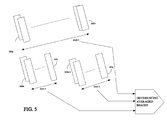
- FIG. 5 is a schematic diagram illustrating the averaging of image sequences and the differencing of the resulting averaged image sequences in accordance with the present invention
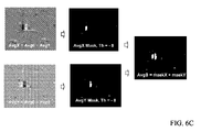
- FIGS. 6A-6E illustrate an exemplary sequence of averaged, differenced and masked sets of images produced during the process of minimizing scintillation and restoring moving objects in the final composite image in accordance with the present invention.
- FIG. 7 is a flow diagram illustrating an exemplary embodiment of a local area process (LAP) performed by the image acquisition and processing unit of FIG. 2 in accordance with the present invention.
- LAP local area process
- FIG. 1 is a schematic diagram 100 illustrating an optical flow of an object 102 traversing an atmospheric turbulence 104 and captured by a focal array 108 via a lens 106 in accordance with the present invention.
- the focal array 108 receives light representing the object 102 , and captures image data signals representing the degraded image of the object 102 .
- the light received can be distorted by atmospheric conditions (or turbulence) 104 , such as rain, snow, fog, smoke, or underwater fluctuations, such that the images captured by focal array 108 are degraded or blurred.
- the focal array 108 is coupled to an image processing system 110 configured to process the captured dynamic images.
- the imaging system 110 includes an image sensing or detection unit 202 , an image acquisition and processing unit 204 , a data recording and storage unit 206 , a display unit 208 , and a communication interface unit 210 .
- an image sensing or detection unit 202 an image acquisition and processing unit 204 , a data recording and storage unit 206 , a display unit 208 , and a communication interface unit 210 .
- one or more of these devices, such as the display unit 208 may be incorporated into the image acquisition and processing unit 104 , hereafter referred to as the processing unit 204 .
- the detection unit 202 comprises a focal plane array of pixels or photodetectors suitable for detecting an input image (e.g. 203 a ), such as an image degraded by atmospheric turbulence, during an integration and acquisition period, which may be triggered by the image acquisition and processing unit 204 .
- an input image e.g. 203 a
- the detector 202 detects and outputs a sequence of input images 203 a - 203 n, as directed by the image acquisition and processing unit 204 .
- the detector 202 may include the lens 106 that focuses light emitted or reflected from the object or scene 102 onto the focal plane array 108 of pixels 212 aa - 212 nn .
- each of the pixels 212 aa - 212 nn accumulates a respective portion of the light from the object or scene and generates a corresponding signal or charge based on the intensity of the light.
- the electrical signals or charges generated by the pixels 212 aa - 212 nn collectively represent an input image 203 a which is output by the detector 202 to the processor 204 .
- each input image 203 a is assumed to correspond to, but not limited to, 256 by 256 pixels, referenced as 212 aa - 212 nn in FIG. 1 .
- the data acquisition and processing unit 204 can be hard-wired circuits or a processor executing a suitable set of program instructions stored on a computer readable storage medium such as a random access memory (RAM), read only memory (ROM), magnetic storage medium (such as magnetic tape, disk or diskette) or optical storage medium (such as compact disk (CD) ROM).
- a computer readable storage medium such as a random access memory (RAM), read only memory (ROM), magnetic storage medium (such as magnetic tape, disk or diskette) or optical storage medium (such as compact disk (CD) ROM).
- the processor 204 can include a central processing unit (CPU) 212 , a static memory 214 and a main memory 216 that can communicate with each other via bus 218 .
- CPU central processing unit
- the processor 204 may include an input/output device 220 that may have an alpha-numeric device, such as a keyboard, a cursor control device, such as a mouse, and a video display device, such as a liquid crystal display (LCD), an organic light emitting diode (OLED), a flat panel display, a solid state display, or a cathode ray tube (CRT).
- an alpha-numeric device such as a keyboard
- a cursor control device such as a mouse
- a video display device such as a liquid crystal display (LCD), an organic light emitting diode (OLED), a flat panel display, a solid state display, or a cathode ray tube (CRT).
- LCD liquid crystal display
- OLED organic light emitting diode
- flat panel display such as a flat panel display
- solid state display such as a solid state display
- CRT cathode ray tube
- the data recording and storage unit 206 hereafter referred to as the memory, can comprise any type of memory including random access memory (RAM), electronically erasable memory (EPROM), and the like. Further, the memory 206 can comprise any type of storage including magnetic or optical drives, a local drive or a network drive, and a floppy disk, hard drive, CD-ROM, DVD-ROM, DVD-RAM, a tape drive, and the like.
- the communication interface 110 can comprise any type of interface for connecting to a communication network, such as a data or voice network, a land-line or wireless network, and the like. It will be recognized that one of ordinary skill in the art would understand how to build a communication interface, and hence, further description of this interface is omitted.
- FIG. 3 a block diagram illustrating an exemplary process 300 for removing scintillation from dynamic images performed by the imaging system 110 of FIG. 2A is shown.
- the process 300 is represented by a plurality of functional processing units or steps, provided in an exemplary identified order, which are executed by the processor 204 .
- the illustrative processing units include an input unit 302 , an image frame averaging unit 304 , an image differencing unit 306 , an image warping unit 308 , and an enhanced image output unit 310 .
- the image warping unit 308 may include a local area processing unit (LAP) 309 .
- LAP local area processing unit
- the processing units can be linked or coupled sequentially as shown, or alternatively a subset of these processing units can be run in parallel with another subset.
- a reduced or streamlined process might adopt fewer processing units, without impacting the intended functionality consistent with the present invention. It should be understood that various aspects of the present application may be used together as would occur to one of ordinary skill in the art without utilizing all of the processing units thereof. In addition, different combinations of these processing units might affect operational speed of the corresponding resulting processes and other intermediary processing outcomes. Accordingly, it should be apparent that other permutations of these processing units can be developed without departing from the spirit and scope of the present invention.
- a set of instructions corresponding to this sequence of processing units is launched on the processor 204 .
- This launching may be performed automatically with activation of the detector 202 .
- the image frames 203 a - 203 n may enter the imaging system 110 at the input unit 302 at real-time rates, nominally at about 30 frames, or a previously recorded suitable video frame sequence is loaded from the memory 216 .
- the image frames 203 a - 203 n form an individual temporal frame sequence, denoted as frame sequence set 1 in FIG. 5 , which is updated in a “first in first out” (FIFO) manner so as to include the most recent image frame, thereby becoming the most updated sequence with each newly acquired or uploaded image frame.
- FIFO first in first out
- the FIFO sequence set 1 is an image buffer queue that is configured to include a predetermined number of input image frames. That is, when this predetermined number is reached, the oldest image frame is discarded and the newest image frame is added, thereby maintaining the same predetermined number of newest image frames.
- the scintillation removal process 300 is initiated at step 402 .
- the frame sequence set 1 which may represent a scintillation video (SV), comprises n successive frames 103 a - 103 n received from the image input unit 302 , at step 404 .
- the first image frame 103 a heads the sequence of image frames 103 a - 103 n, which may be captured by the detector 102 at real time rates, nominally about 30 frames per second (fps).
- the sequence of image frames 103 a - 103 n may be retrieved from the main memory 216 of the processor 204 or from the memory 206 as a previously stored sequence of image frames.
- the received first image frame 103 a may be communicated to and displayed by the display unit 208 if the user desires and can be stored unprocessed, if newly acquired, in the memory 206 .
- Steps 404 and 405 correspond to the input unit 302 in FIG. 3 .
- the frame sequence set 1 is subdivided into a plurality of subsets of frames, which may be contiguous and/or overlapping. Preferably, these subsets of frames do not have the same of frames, so as to produce running scene averages of various durations.
- Each of the plurality of subsets of frames is then averaged to form a series of average image sequences, at step 408 .
- the frame sequence set 1 is averaged to form a first average image sequence, denoted AIS 0 or Avg 0 , as shown in FIG. 5 .
- a second average image sequence Avg 1 may be formed by averaging image frames 103 a to 103 i
- a third average image sequence Avg 2 may be formed by averaging image frames 103 i+ 1 to 103 j, where j ⁇ n.
- the frame averaging of these subsets of frames which is performed by the frame averaging unit 304 , is used to achieve a stabilized background image by minimizing or even removing scintillation distortions from the images.
- a check is performed as to whether an additional subset of frames is queued for processing. In the affirmative, this additional subset of frames is averaged to produce Avg 3 (not shown). Otherwise, at step 412 the first average image sequence Avg 0 is selected as a reference averaged sequence.
- each of the Avg 1 and Avg 2 sequences are differenced from the reference averaged sequence Avg 0 by the image differencing unit 306 .
- the scintillation is substantially minimized or even removed but moving objects remain as motion blurs.
- this differencing or comparison of the averaged image sequences enables the determination of the location of the moving objects in the images.
- the averaged image sequence Avg 1 is subtracted from the reference averaged sequence Avg 0 to produce an image difference, denoted as AvgX.
- the averaged image sequence Avg 2 is subtracted from the reference averaged sequence Avg 0 to produce an image difference, denoted as AvgY.
- These resulting image differences AvgX and AvgY are then added together to produce image difference AvgZ. This subtracting and subsequent adding of image differences result in the determination of a mask region in the image difference AvgZ from where the moving objects need to be extracted.
- AvgZMask image is filtered or cleaned by a series of isotropic operators, for example an image erosion operator followed by an image dilation operator, as shown in FIG. 6B .
- a threshold is also applied to the above determined image differences AvgX and AvgY to produce respective masks MaskX and MaskY, which are in turn added to each other to produce image AvgB. That is, MaskX and MaskY are combined to form the composite mask image AvgB, as shown in FIG. 6C .
- the filtered AvgZMask is combined with the composite mask image AvgB to produce a final mask, denoted as ImgTh, which indicates the region or regions to be replaced.
- ImgTh the final mask
- an image offset is produced by overlaying the reference averaged sequence Avg 0 over the final mask ImgTh. Further, the region or regions determined above to be replaced are removed or cut out from the reference averaged sequence Avg 0 to produce ImgAvg or Img 0 , at step 424 .
- step 426 the image offset ImgOffSet is combined with ImgAvg to derive a final image ImgFinal, in which the determined final mask ImgTh is inserted in the evaluated masked region, as shown in FIG. 6E .
- this masking process enables extracting averaged moving regions and replacing them with the mask of corresponding true temporal regions.
- Steps 416 through 426 correspond to the processing unit 308 .
- another final image ImgFinal is similarly produced using an updated frame sequence set 1 .
- This updated frame sequence 1 is updated to become frame sequence 2 by adding the newest image frame 103 in+ 1 received from the image input unit 302 or uploaded from the data storage memory 206 or the CPU memory 216 , and dropping the oldest image frame 103 a.
- the frame sequence set 2 comprises n successive frames 103 a+ 1- 103 n+ 1 that are processed to produce the another final image ImgFinal.
- each of the produced final images ImgFinal may include parts that are undesirably light or dark
- a LAP process may be utilized to develop desirable contrast and brightness of the pixels of these problematic parts, at step 428 .
- the LAP unit 309 serves to improve image interpretability so as to allow an observer to see objects in the images that may otherwise be difficult or near impossible to assess in the original high-contrasted and high-brightened images.
- the final images ImgFinal are output by the image output unit 310 , at step 430 .
- One exemplary embodiment of the LAP unit 420 is functionally represented by an algorithmic flow diagram illustrated in FIG. 7 .
- Each of the final images ImgFinal is initially processed in a sharpening routine 704 which sharpens images, such as the multi-resolution un-sharp process discussed above.
- a tiling routine 706 which involves breaking or dividing the final images ImgFinal into tiles, having about 20 to 80 pixels to a side. This tiling of images enables each tile to be processed or treated independently by predetermined subsequent processing units, such as the local histogram unit 708 .
- the local histogram process 708 enables an efficient redistribution of dynamic range of each of the tiles composing the final image ImgFinal, which can achieve a maximum dynamic range for each tile.
- a mosaic routine 710 is used to reassemble or bring together all tiles the final image ImgFinal in the same arrangement they had prior to the tiling routine 706 .
- a global sharpening is performed on the whole regrouped final image ImgFinal by the global image process 712 so as to achieve optimum image acuity.
- the global sharpening process 712 emphasizes edges and other high frequency components of the final image ImgFinal, as well as differences between adjacent light and dark areas or spots.
- sharpening processes involve employing filters to decompose images into many frequency bands, attenuating low frequency bands, amplifying high frequency bands, and recombining modified spatial frequency bands.
Abstract
Description
Claims (20)
Priority Applications (5)
| Application Number | Priority Date | Filing Date | Title |
|---|---|---|---|
| US12/130,294 US8073199B2 (en) | 2008-05-30 | 2008-05-30 | Method for minimizing scintillation in dynamic images |
| PCT/US2009/045565 WO2009146395A1 (en) | 2008-05-30 | 2009-05-29 | Method for minimizing scintillation in dynamic images |
| US13/286,395 US8526676B1 (en) | 2008-05-30 | 2011-11-01 | Method for minimizing scintillation in dynamic images |
| US13/975,173 US8768092B2 (en) | 2008-05-30 | 2013-08-23 | Method for minimizing scintillation in dynamic images |
| US14/287,984 US20140341470A1 (en) | 2008-05-30 | 2014-05-27 | Method for minimizing scintillation in dynamic images |
Applications Claiming Priority (1)
| Application Number | Priority Date | Filing Date | Title |
|---|---|---|---|
| US12/130,294 US8073199B2 (en) | 2008-05-30 | 2008-05-30 | Method for minimizing scintillation in dynamic images |
Related Child Applications (1)
| Application Number | Title | Priority Date | Filing Date |
|---|---|---|---|
| US13/286,395 Continuation US8526676B1 (en) | 2008-05-30 | 2011-11-01 | Method for minimizing scintillation in dynamic images |
Publications (2)
| Publication Number | Publication Date |
|---|---|
| US20090297059A1 US20090297059A1 (en) | 2009-12-03 |
| US8073199B2 true US8073199B2 (en) | 2011-12-06 |
Family
ID=41377592
Family Applications (4)
| Application Number | Title | Priority Date | Filing Date |
|---|---|---|---|
| US12/130,294 Active 2030-09-20 US8073199B2 (en) | 2008-05-30 | 2008-05-30 | Method for minimizing scintillation in dynamic images |
| US13/286,395 Active US8526676B1 (en) | 2008-05-30 | 2011-11-01 | Method for minimizing scintillation in dynamic images |
| US13/975,173 Active US8768092B2 (en) | 2008-05-30 | 2013-08-23 | Method for minimizing scintillation in dynamic images |
| US14/287,984 Abandoned US20140341470A1 (en) | 2008-05-30 | 2014-05-27 | Method for minimizing scintillation in dynamic images |
Family Applications After (3)
| Application Number | Title | Priority Date | Filing Date |
|---|---|---|---|
| US13/286,395 Active US8526676B1 (en) | 2008-05-30 | 2011-11-01 | Method for minimizing scintillation in dynamic images |
| US13/975,173 Active US8768092B2 (en) | 2008-05-30 | 2013-08-23 | Method for minimizing scintillation in dynamic images |
| US14/287,984 Abandoned US20140341470A1 (en) | 2008-05-30 | 2014-05-27 | Method for minimizing scintillation in dynamic images |
Country Status (2)
| Country | Link |
|---|---|
| US (4) | US8073199B2 (en) |
| WO (1) | WO2009146395A1 (en) |
Cited By (1)
| Publication number | Priority date | Publication date | Assignee | Title |
|---|---|---|---|---|
| US8768092B2 (en) * | 2008-05-30 | 2014-07-01 | Drs Rsta, Inc. | Method for minimizing scintillation in dynamic images |
Families Citing this family (27)
| Publication number | Priority date | Publication date | Assignee | Title |
|---|---|---|---|---|
| US8963949B2 (en) * | 2009-04-22 | 2015-02-24 | Qualcomm Incorporated | Image selection and combination method and device |
| JP5680524B2 (en) * | 2011-12-09 | 2015-03-04 | 株式会社日立国際電気 | Image processing device |
| US9019431B2 (en) | 2012-09-28 | 2015-04-28 | Digital Ally, Inc. | Portable video and imaging system |
| US10638221B2 (en) | 2012-11-13 | 2020-04-28 | Adobe Inc. | Time interval sound alignment |
| US9355649B2 (en) | 2012-11-13 | 2016-05-31 | Adobe Systems Incorporated | Sound alignment using timing information |
| US10249321B2 (en) | 2012-11-20 | 2019-04-02 | Adobe Inc. | Sound rate modification |
| US9165373B2 (en) | 2013-03-11 | 2015-10-20 | Adobe Systems Incorporated | Statistics of nearest neighbor fields |
| US9025822B2 (en) | 2013-03-11 | 2015-05-05 | Adobe Systems Incorporated | Spatially coherent nearest neighbor fields |
| US9031345B2 (en) * | 2013-03-11 | 2015-05-12 | Adobe Systems Incorporated | Optical flow accounting for image haze |
| US9129399B2 (en) | 2013-03-11 | 2015-09-08 | Adobe Systems Incorporated | Optical flow with nearest neighbor field fusion |
| JP6104680B2 (en) * | 2013-03-21 | 2017-03-29 | 株式会社日立国際電気 | Image processing apparatus, imaging apparatus, monitoring system, encoding apparatus, and image processing method |
| WO2014155913A1 (en) * | 2013-03-25 | 2014-10-02 | パナソニック株式会社 | Image interpolation device, image processing device, and image interpolation method |
| GB201313682D0 (en) | 2013-07-31 | 2013-12-18 | Mbda Uk Ltd | Method and apparatus for tracking an object |
| GB201313680D0 (en) * | 2013-07-31 | 2014-01-08 | Mbda Uk Ltd | Image processing |
| GB201313681D0 (en) | 2013-07-31 | 2014-01-08 | Mbda Uk Ltd | Image processing |
| JP2015130632A (en) * | 2014-01-08 | 2015-07-16 | 株式会社リコー | Image processing apparatus, transmission and reception system, image processing method, and program |
| US10062411B2 (en) | 2014-12-11 | 2018-08-28 | Jeffrey R. Hay | Apparatus and method for visualizing periodic motions in mechanical components |
| US9704266B2 (en) | 2014-12-11 | 2017-07-11 | Rdi, Llc | Non-contacting monitor for bridges and civil structures |
| US10755395B2 (en) * | 2015-11-27 | 2020-08-25 | Canon Medical Systems Corporation | Dynamic image denoising using a sparse representation |
| US11423551B1 (en) | 2018-10-17 | 2022-08-23 | Rdi Technologies, Inc. | Enhanced presentation methods for visualizing motion of physical structures and machinery |
| TWI692742B (en) * | 2018-11-26 | 2020-05-01 | 國立中山大學 | Enhancement method of low-light underwater image |
| CN111292233B (en) * | 2018-12-06 | 2023-08-15 | 成都微晶景泰科技有限公司 | Lens array image stitching method, device and storage medium |
| US11373317B1 (en) | 2020-01-24 | 2022-06-28 | Rdi Technologies, Inc. | Measuring the speed of rotation or reciprocation of a mechanical component using one or more cameras |
| US11710245B2 (en) * | 2020-02-25 | 2023-07-25 | Jack Wade | Real-time marine snow noise removal from underwater video |
| US11282213B1 (en) | 2020-06-24 | 2022-03-22 | Rdi Technologies, Inc. | Enhanced analysis techniques using composite frequency spectrum data |
| US11322182B1 (en) | 2020-09-28 | 2022-05-03 | Rdi Technologies, Inc. | Enhanced visualization techniques using reconstructed time waveforms |
| US11640655B2 (en) * | 2021-04-14 | 2023-05-02 | Raytheon Company | Systems and methods for image turbulence correction of moving targets |
Citations (8)
| Publication number | Priority date | Publication date | Assignee | Title |
|---|---|---|---|---|
| US5448053A (en) | 1993-03-01 | 1995-09-05 | Rhoads; Geoffrey B. | Method and apparatus for wide field distortion-compensated imaging |
| US6556708B1 (en) * | 1998-02-06 | 2003-04-29 | Compaq Computer Corporation | Technique for classifying objects within an image |
| US20050074140A1 (en) | 2000-08-31 | 2005-04-07 | Grasso Donald P. | Sensor and imaging system |
| US20050089194A1 (en) * | 2003-10-24 | 2005-04-28 | Matthew Bell | Method and system for processing captured image information in an interactive video display system |
| US7068837B2 (en) * | 2000-11-24 | 2006-06-27 | Nihon University | Image processing method |
| US7139421B1 (en) * | 1999-06-29 | 2006-11-21 | Cognex Corporation | Methods and apparatuses for detecting similar features within an image |
| US20080279476A1 (en) * | 2007-05-11 | 2008-11-13 | Koninklijke Philips Electronics, N.V. | Method for producing an image and system for producing an image |
| US7545967B1 (en) * | 2002-09-18 | 2009-06-09 | Cornell Research Foundation Inc. | System and method for generating composite subtraction images for magnetic resonance imaging |
Family Cites Families (15)
| Publication number | Priority date | Publication date | Assignee | Title |
|---|---|---|---|---|
| CA2446150C (en) * | 2001-05-04 | 2013-01-08 | Legend Films, Llc | Image sequence enhancement system and method |
| US7127090B2 (en) * | 2001-07-30 | 2006-10-24 | Accuimage Diagnostics Corp | Methods and systems for combining a plurality of radiographic images |
| US6836570B2 (en) * | 2001-11-14 | 2004-12-28 | Eastman Kodak Company | Method for contrast-enhancement of digital portal images |
| US20130107938A9 (en) * | 2003-05-28 | 2013-05-02 | Chad Fogg | Method And Apparatus For Scalable Video Decoder Using An Enhancement Stream |
| US7269299B2 (en) * | 2003-10-10 | 2007-09-11 | Orbimage Si Opco, Inc. | Image warp |
| US8059174B2 (en) * | 2006-05-31 | 2011-11-15 | Ess Technology, Inc. | CMOS imager system with interleaved readout for providing an image with increased dynamic range |
| US20080051648A1 (en) * | 2006-08-25 | 2008-02-28 | Suri Jasjit S | Medical image enhancement system |
| US8830340B2 (en) * | 2006-09-08 | 2014-09-09 | Sri International | System and method for high performance image processing |
| US8203764B2 (en) * | 2007-06-27 | 2012-06-19 | Lexmark International, Inc. | Phased illumination method for image capture system |
| US7969475B2 (en) * | 2007-07-17 | 2011-06-28 | Seiko Epson Corporation | Low memory auto-focus and exposure system for large multi-frame image acquisition |
| US7986356B2 (en) * | 2007-07-25 | 2011-07-26 | Hewlett-Packard Development Company, L.P. | System and method for determining a gamma curve of a display device |
| US8411938B2 (en) * | 2007-11-29 | 2013-04-02 | Sri International | Multi-scale multi-camera adaptive fusion with contrast normalization |
| CA2650180C (en) * | 2008-01-17 | 2015-04-07 | Imds America Inc. | Image binarization using dynamic sub-image division |
| US8200046B2 (en) * | 2008-04-11 | 2012-06-12 | Drs Rsta, Inc. | Method and system for enhancing short wave infrared images using super resolution (SR) and local area processing (LAP) techniques |
| US8073199B2 (en) * | 2008-05-30 | 2011-12-06 | Drs Rsta, Inc. | Method for minimizing scintillation in dynamic images |
-
2008
- 2008-05-30 US US12/130,294 patent/US8073199B2/en active Active
-
2009
- 2009-05-29 WO PCT/US2009/045565 patent/WO2009146395A1/en active Application Filing
-
2011
- 2011-11-01 US US13/286,395 patent/US8526676B1/en active Active
-
2013
- 2013-08-23 US US13/975,173 patent/US8768092B2/en active Active
-
2014
- 2014-05-27 US US14/287,984 patent/US20140341470A1/en not_active Abandoned
Patent Citations (9)
| Publication number | Priority date | Publication date | Assignee | Title |
|---|---|---|---|---|
| US5448053A (en) | 1993-03-01 | 1995-09-05 | Rhoads; Geoffrey B. | Method and apparatus for wide field distortion-compensated imaging |
| US6556708B1 (en) * | 1998-02-06 | 2003-04-29 | Compaq Computer Corporation | Technique for classifying objects within an image |
| US7139421B1 (en) * | 1999-06-29 | 2006-11-21 | Cognex Corporation | Methods and apparatuses for detecting similar features within an image |
| US20050074140A1 (en) | 2000-08-31 | 2005-04-07 | Grasso Donald P. | Sensor and imaging system |
| US7068837B2 (en) * | 2000-11-24 | 2006-06-27 | Nihon University | Image processing method |
| US7545967B1 (en) * | 2002-09-18 | 2009-06-09 | Cornell Research Foundation Inc. | System and method for generating composite subtraction images for magnetic resonance imaging |
| US20090245606A1 (en) * | 2002-09-18 | 2009-10-01 | Cornell Research Foundation, Inc. | System and method for generating composite substraction images for magnetic resonance imaging |
| US20050089194A1 (en) * | 2003-10-24 | 2005-04-28 | Matthew Bell | Method and system for processing captured image information in an interactive video display system |
| US20080279476A1 (en) * | 2007-05-11 | 2008-11-13 | Koninklijke Philips Electronics, N.V. | Method for producing an image and system for producing an image |
Non-Patent Citations (1)
| Title |
|---|
| International Search Report corresponding to PCT/US09/45565 dated Jul. 16, 2009. |
Cited By (2)
| Publication number | Priority date | Publication date | Assignee | Title |
|---|---|---|---|---|
| US8768092B2 (en) * | 2008-05-30 | 2014-07-01 | Drs Rsta, Inc. | Method for minimizing scintillation in dynamic images |
| US20140341470A1 (en) * | 2008-05-30 | 2014-11-20 | Drs Rsta, Inc. | Method for minimizing scintillation in dynamic images |
Also Published As
| Publication number | Publication date |
|---|---|
| US20130343671A1 (en) | 2013-12-26 |
| WO2009146395A1 (en) | 2009-12-03 |
| US8768092B2 (en) | 2014-07-01 |
| US8526676B1 (en) | 2013-09-03 |
| US20140341470A1 (en) | 2014-11-20 |
| US20090297059A1 (en) | 2009-12-03 |
Similar Documents
| Publication | Publication Date | Title |
|---|---|---|
| US8073199B2 (en) | Method for minimizing scintillation in dynamic images | |
| JP6635384B2 (en) | Image processing apparatus, monitoring system including the same, and image processing method | |
| US8200046B2 (en) | Method and system for enhancing short wave infrared images using super resolution (SR) and local area processing (LAP) techniques | |
| US8311367B2 (en) | Image processing device | |
| EP2568438B1 (en) | Image defogging method and system | |
| US9177363B1 (en) | Method and image processing apparatus for image visibility restoration | |
| US6459818B1 (en) | System for recovery of degraded images | |
| US10600158B2 (en) | Method of video stabilization using background subtraction | |
| US20110025919A1 (en) | Automated Video Data Fusion Method | |
| US20100045674A1 (en) | Image processing device using selective neighboring voxel removal and related methods | |
| US20080159649A1 (en) | Directional fir filtering for image artifacts reduction | |
| US20100129003A1 (en) | Method and system for enhancing images using multi-resolution histogram shaping | |
| CN101742123A (en) | Image processing apparatus and method | |
| KR101813292B1 (en) | Method for improving images | |
| CN102082912A (en) | Image capturing apparatus and image processing method | |
| Cao et al. | Spatially adaptive column fixed-pattern noise correction in infrared imaging system using 1D horizontal differential statistics | |
| KR101287521B1 (en) | Apparatus and method for generating high dynamic range image based on single frame | |
| Baumgartner et al. | Improving FLIR ATR performance in a turbulent atmosphere with a moving platform | |
| KR102183518B1 (en) | Image-processing apparatus to reduce staircase artifacts from an image signal | |
| JP6080487B2 (en) | Moving object detection apparatus and control method thereof | |
| CN112055255A (en) | Shooting image quality optimization method and device, smart television and readable storage medium | |
| Schwering et al. | Image enhancement technology research for army applications | |
| Fraser et al. | Anisoplanatic image restoration at ADFA | |
| JP2011198016A (en) | Image processing device | |
| CN109660730B (en) | Image processing method and system |
Legal Events
| Date | Code | Title | Description |
|---|---|---|---|
| AS | Assignment |
Owner name: DRS SENSORS & TARGETING SYSTEMS, INC., FLORIDA Free format text: ASSIGNMENT OF ASSIGNORS INTEREST;ASSIGNORS:LEE, HARRY C.;PACE, TERESA L.;FUENTES, MARLON J.;SIGNING DATES FROM 20090509 TO 20090526;REEL/FRAME:022739/0280 |
|
| AS | Assignment |
Owner name: DRS RSTA, INC.,TEXAS Free format text: CHANGE OF NAME;ASSIGNOR:DRS SENSORS & TARGETING SYSTEMS, INC.;REEL/FRAME:023905/0520 Effective date: 20090512 Owner name: DRS RSTA, INC., TEXAS Free format text: CHANGE OF NAME;ASSIGNOR:DRS SENSORS & TARGETING SYSTEMS, INC.;REEL/FRAME:023905/0520 Effective date: 20090512 |
|
| STCF | Information on status: patent grant |
Free format text: PATENTED CASE |
|
| AS | Assignment |
Owner name: DRS NETWORK & IMAGING SYSTEMS, LLC, FLORIDA Free format text: CHANGE OF NAME;ASSIGNOR:DRS RSTA, INC.;REEL/FRAME:035349/0060 Effective date: 20140722 |
|
| FPAY | Fee payment |
Year of fee payment: 4 |
|
| MAFP | Maintenance fee payment |
Free format text: PAYMENT OF MAINTENANCE FEE, 8TH YEAR, LARGE ENTITY (ORIGINAL EVENT CODE: M1552); ENTITY STATUS OF PATENT OWNER: LARGE ENTITY Year of fee payment: 8 |
|
| MAFP | Maintenance fee payment |
Free format text: PAYMENT OF MAINTENANCE FEE, 12TH YEAR, LARGE ENTITY (ORIGINAL EVENT CODE: M1553); ENTITY STATUS OF PATENT OWNER: LARGE ENTITY Year of fee payment: 12 |