US8074367B2 - Motion sensor for measurement in a dynamic environment of co-existing tilt and horizontal acceleration - Google Patents
Motion sensor for measurement in a dynamic environment of co-existing tilt and horizontal acceleration Download PDFInfo
- Publication number
- US8074367B2 US8074367B2 US12/965,847 US96584710A US8074367B2 US 8074367 B2 US8074367 B2 US 8074367B2 US 96584710 A US96584710 A US 96584710A US 8074367 B2 US8074367 B2 US 8074367B2
- Authority
- US
- United States
- Prior art keywords
- motion
- tilt
- sensing device
- acceleration
- accelerometer
- Prior art date
- Legal status (The legal status is an assumption and is not a legal conclusion. Google has not performed a legal analysis and makes no representation as to the accuracy of the status listed.)
- Active
Links
Images


Classifications
-
- G—PHYSICS
- G01—MEASURING; TESTING
- G01P—MEASURING LINEAR OR ANGULAR SPEED, ACCELERATION, DECELERATION, OR SHOCK; INDICATING PRESENCE, ABSENCE, OR DIRECTION, OF MOVEMENT
- G01P15/00—Measuring acceleration; Measuring deceleration; Measuring shock, i.e. sudden change of acceleration
- G01P15/006—Measuring acceleration; Measuring deceleration; Measuring shock, i.e. sudden change of acceleration by making use of fluid seismic masses
-
- G—PHYSICS
- G01—MEASURING; TESTING
- G01C—MEASURING DISTANCES, LEVELS OR BEARINGS; SURVEYING; NAVIGATION; GYROSCOPIC INSTRUMENTS; PHOTOGRAMMETRY OR VIDEOGRAMMETRY
- G01C9/00—Measuring inclination, e.g. by clinometers, by levels
- G01C9/12—Measuring inclination, e.g. by clinometers, by levels by using a single pendulum plumb lines G01C15/10
-
- G—PHYSICS
- G01—MEASURING; TESTING
- G01P—MEASURING LINEAR OR ANGULAR SPEED, ACCELERATION, DECELERATION, OR SHOCK; INDICATING PRESENCE, ABSENCE, OR DIRECTION, OF MOVEMENT
- G01P15/00—Measuring acceleration; Measuring deceleration; Measuring shock, i.e. sudden change of acceleration
- G01P15/02—Measuring acceleration; Measuring deceleration; Measuring shock, i.e. sudden change of acceleration by making use of inertia forces using solid seismic masses
- G01P15/03—Measuring acceleration; Measuring deceleration; Measuring shock, i.e. sudden change of acceleration by making use of inertia forces using solid seismic masses by using non-electrical means
- G01P15/032—Measuring acceleration; Measuring deceleration; Measuring shock, i.e. sudden change of acceleration by making use of inertia forces using solid seismic masses by using non-electrical means by measuring the displacement of a movable inertial mass
-
- G—PHYSICS
- G01—MEASURING; TESTING
- G01P—MEASURING LINEAR OR ANGULAR SPEED, ACCELERATION, DECELERATION, OR SHOCK; INDICATING PRESENCE, ABSENCE, OR DIRECTION, OF MOVEMENT
- G01P21/00—Testing or calibrating of apparatus or devices covered by the preceding groups
Definitions
- This invention relates to a motion sensor for measurement in a dynamic environment of co-existing tilt and acceleration.
- legacy sensors cannot distinguish between tilt and acceleration and, therefore, cannot measure the signal generated by tilt and the signal generated by acceleration separately in dynamic environment.
- a tilt sensor or an accelerometer or both are mounted in a moving vehicle, which is a dynamic environment. It is very difficult to measure either tilt or acceleration or both of them separately because of interference from tilt with acceleration and interference of acceleration with tilt.
- Robert L. Forward designed a method to directly measure these two signals in separate forms. However, he further stated that this method was only academically correct. Robert L. Forward proposed another method to separate these two terms by measuring the resonant frequencies of the sensors and determine the tensor components.
- French, et al. also used resonant frequency to decrease the noise brought by the horizontal acceleration to measure gravitational field.
- Dosch, et al. calculated the gravitational field with better accuracy by accounting for undesired accelerations picked up by accelerometers having input axes that are not parallel to the gradiometer disc.
- a primary object and feature of the present invention is to overcome the above-mentioned problems and fulfill the above-mentioned needs.
- Another object and feature of the present invention is to provide a motion sensor that can sense tilt and acceleration whether occurring separately or concurrently. It is a further object and feature of the present invention to provide a sensor structure that can incorporate various accelerometers and the like. It is a further object and feature of the present invention to provide calculation methods for determination of various parameters based on the measurement results, such as acceleration, tilt, linear speed, moving distance etc with co-existing tilt and linear acceleration in a dynamic environment. It is a further object of the present invention to provide a tilt and acceleration sensor that may be implemented in various sizes, from micro-electro-mechanical system (MEMS) to box-level motion sensing devices.
- MEMS micro-electro-mechanical system
- MEMS micro-electro-mechanical system
- This invention uses a motion sensing device having at least two accelerometers with at least one accelerometer mounted to a substrate and with at least one other sensor mounted firmly on the end part of a pendulum.
- the pendulum is hung on the substrate vertically and can rotate freely in a single geometric plane, preferably in critically damping fluid in a gravitational field.
- the arm of the pendulum is always parallel with the gravitational direction when the substrate is tilted either if there is an additional linear acceleration or no additional linear acceleration.
- the first accelerometer senses the mixed signals generated by both tilt and linear horizontal acceleration without distinguishing the two components.
- the second accelerometer is able to only measure the linear horizontal acceleration without the interference from tilt.
- the tilt can be calculated from the signals output from the first accelerometer and the second accelerometer.
- the motion in the dynamic environment of co-existing influences of both horizontal acceleration along the level direction and tilt along the gravitational direction, can be separated into two components, tilt and linear acceleration, respectively.
- both tilt and acceleration can be measured separately in the co-existing dynamic environment.
- the present invention provides a motion-sensing device for sensing tilt and linear horizontal acceleration when either tilt, horizontal acceleration, or tilt and horizontal acceleration acting concurrently, influence the device, the device including: a substrate having a top and a bottom. The top side of the substrate is parallel with the gravitational direction.
- a first accelerometer mounted to the top of the substrate with the sensing axis vertical to the gravitational direction; a pendulum flexibly coupled to the top of the substrate through a pendulum rod and flexible wire or a pendulum rod with a ring at the end and can rotate around a rod which is firmly mounted vertically on the substrate and can swing in the geometric plane parallel to the top side of the substrate; and a second accelerometer fixed to the pendulum with the sensing axis along the horizontal direction and vertical to the gravitational direction also.
- FIG. 1 is a view of a tilt sensor as shown in U.S. Pat. No. 6,282,804 to the present inventor;
- FIG. 2 is a view of a prior art motion sensor as shown in U.S. patent application Ser. No. 12/625,333 to the present inventor, illustrating a combined tilt and motion sensor having two spring-mass systems concurrently under the influence of tilt and acceleration;
- FIG. 3A is a front diagrammatic view illustrating an exemplary embodiment of a motion-sensing device including parts populated on an exemplary printed circuit board (PCB), according to a preferred embodiment of the present invention
- FIG. 3B is a side diagrammatic view illustrating the exemplary the exemplary motion-sensing device with populated PCB having two accelerometers and one pendulum system, according to a preferred embodiment of the present invention
- FIG. 3C is a front diagrammatic view illustrating an alternate embodiment of the pendulum system of FIG. 3A , according to a preferred embodiment of the present invention
- FIG. 4 is a front diagrammatic view illustrating the motion-sensing device under the influence of tilt but not linear horizontal acceleration, according to a preferred embodiment of the present invention
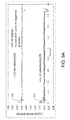
- FIG. 5 is a front diagrammatic view illustrating the exemplary motion-sensing device under the influence of linear horizontal acceleration but not tilt, according to a preferred embodiment of the present invention
- FIG. 6 is a front diagrammatic view illustrating the motion-sensing device under the influence of co-existing linear horizontal acceleration and tilt, according to a preferred embodiment of the present invention
- FIG. 7 is a front diagrammatic view illustrating an exemplary embodiment of a motion stage having one linear horizontal motion stage and a rotary stage, a motion control interface and a computer based motion control and data acquisition system, according to a preferred embodiment of the present invention
- FIG. 8A illustrates first test results from both accelerometers for measurement of co-existing tilt and linear horizontal acceleration using the exemplary sensor of FIG. 3 in the motion stage of FIG. 7 in a dynamic environment, for the case of no tilt with positive and negative accelerations, according to a preferred embodiment of the present invention
- FIG. 8B illustrates first test results for the motion-sensing device for measurement of co-existing tilt and linear horizontal acceleration using the exemplary motion-sensing device of FIG. 3 in the motion stage of FIG. 7 in a dynamic environment, for the case of no tilt with positive and negative accelerations, according to a preferred embodiment of the present invention
- FIG. 8C illustrates calculated distance as a function of time for the first test results for both accelerometers for measurement of co-existing tilt and linear horizontal acceleration using the exemplary motion-sensing device of FIG. 3 in the motion stage of FIG. 7 in a dynamic environment, for the case of no tilt with positive and negative accelerations, according to a preferred embodiment of the present invention
- FIG. 8D illustrates calculated speed as a function of time for the first test results for both accelerometers for measurement of co-existing tilt and linear horizontal acceleration using the exemplary motion-sensing device of FIG. 3 in the motion stage of FIG. 7 in a dynamic environment, for the case of no tilt with positive and negative accelerations, according to a preferred embodiment of the present invention
- FIG. 9A illustrates second test results from both accelerometers for measurement of co-existing tilt and linear horizontal acceleration using the exemplary motion-sensing device of FIG. 3 in the motion stage of FIG. 7 in a dynamic environment, for the case of ⁇ 30° tilt with negative and positive linear accelerations, according to a preferred embodiment of the present invention
- FIG. 9B illustrates second test results for the motion-sensing device for measurement of co-existing tilt and linear horizontal acceleration using the exemplary motion-sensing device of FIG. 3 in the motion stage of FIG. 7 in a dynamic environment, for the case of ⁇ 30° tilt with negative and positive linear accelerations, according to a preferred embodiment of the present invention
- FIG. 9C illustrates calculated distance as a function of time for the second test results for both accelerometers for measurement of co-existing tilt and linear horizontal acceleration using the exemplary motion-sensing device of FIG. 3 in the motion stage of FIG. 7 in a dynamic environment, for the case of ⁇ 30° tilt with negative and positive linear accelerations, according to a preferred embodiment of the present invention
- FIG. 9D illustrates calculated speed as a function of time for the second test results for both accelerometers for measurement of co-existing tilt and linear horizontal acceleration using the exemplary motion-sensing device of FIG. 3 in the motion stage of FIG. 7 in a dynamic environment, for the case of ⁇ 30° tilt with negative and positive linear accelerations, according to a preferred embodiment of the present invention
- FIG. 10A illustrates third test results from both accelerometers for measurement of co-existing tilt and linear horizontal acceleration using the exemplary motion-sensing device of FIG. 3 in the motion stage of FIG. 7 in a dynamic environment, for the case of ⁇ 40° tilt with positive and negative accelerations, according to a preferred embodiment of the present invention
- FIG. 10B illustrates third test results for the motion-sensing device for measurement of co-existing tilt and linear horizontal acceleration using the exemplary motion-sensing device of FIG. 3 in the motion stage of FIG. 7 in a dynamic environment, for the case of ⁇ 40° tilt with positive and negative accelerations, according to a preferred embodiment of the present invention
- FIG. 10C illustrates calculated distance as a function of time for the third test results for both accelerometers for measurement of co-existing tilt and linear horizontal acceleration using the exemplary motion-sensing device of FIG. 3 in the motion stage of FIG. 7 in a dynamic environment, for the case of ⁇ 40° tilt with positive and negative accelerations, according to a preferred embodiment of the present invention
- FIG. 10D illustrates calculated speed as a function of time for the third test results for both accelerometers for measurement of co-existing tilt and linear horizontal acceleration using the exemplary motion-sensing device of FIG. 3 in the motion stage of FIG. 7 in a dynamic environment, for the case of ⁇ 40° tilt with positive and negative accelerations, according to a preferred embodiment of the present invention
- FIG. 11A illustrates fourth test results from both accelerometers for measurement of co-existing tilt and linear horizontal acceleration using the exemplary motion-sensing device of FIG. 3 in the motion stage of FIG. 7 in a dynamic environment, for the case of 60° tilt with negative and positive linear accelerations, according to a preferred embodiment of the present invention
- FIG. 11B illustrates fourth test results for the motion-sensing device for measurement of co-existing tilt and linear horizontal acceleration using the exemplary motion-sensing device of FIG. 3 in the motion stage of FIG. 7 in a dynamic environment, for the case of 60° tilt with negative and positive linear accelerations, according to a preferred embodiment of the present invention
- FIG. 11C illustrates calculated distance as a function of time for the fourth test results for both accelerometers for measurement of co-existing tilt and linear horizontal acceleration using the exemplary motion-sensing device of FIG. 3 in the motion stage of FIG. 7 in a dynamic environment, for the case of 60° tilt with negative and positive linear accelerations, according to a preferred embodiment of the present invention
- FIG. 11D illustrates calculated speed as a function of time for the fourth test results for both accelerometers for measurement of co-existing tilt and linear horizontal acceleration using the exemplary motion-sensing device of FIG. 3 in the motion stage of FIG. 7 in a dynamic environment, for the case of 60° tilt with negative and positive linear accelerations, according to a preferred embodiment of the present invention
- FIG. 12A illustrates fifth test results from both accelerometers for measurement of co-existing tilt and linear horizontal acceleration using the exemplary motion-sensing device of FIG. 3 in the motion stage of FIG. 7 in a dynamic environment, for the case of ⁇ 40° tilt with positive and negative accelerations, according to a preferred embodiment of the present invention
- FIG. 12B illustrates fifth test results for the motion-sensing device for measurement of co-existing tilt and linear horizontal acceleration using the exemplary motion-sensing device of FIG. 3 in the motion stage of FIG. 7 in a dynamic environment, for the case of ⁇ 40° tilt with positive and negative accelerations, according to a preferred embodiment of the present invention
- FIG. 12C illustrates calculated distance as a function of time for the fifth test results for both accelerometers for measurement of co-existing tilt and linear horizontal acceleration using the exemplary motion-sensing device of FIG. 3 in the motion stage of FIG. 7 in a dynamic environment, for the case of ⁇ 40° tilt with positive and negative accelerations, according to a preferred embodiment of the present invention
- FIG. 12D illustrates calculated speed as a function of time for the fifth test results for both accelerometers for measurement of co-existing tilt and linear horizontal acceleration using the exemplary motion-sensing device of FIG. 3 in the motion stage of FIG. 7 in a dynamic environment, for the case of ⁇ 40° tilt with positive and negative accelerations, according to a preferred embodiment of the present invention
- FIG. 13A illustrates sixth test results from both accelerometers for measurement of co-existing tilt and linear horizontal acceleration using the exemplary motion-sensing device of FIG. 3 in the motion stage of FIG. 7 in a dynamic environment, for the case of ⁇ 30° tilt with negative and positive linear accelerations, according to a preferred embodiment of the present invention
- FIG. 13B illustrates sixth test results for the tilt sensor for measurement of co-existing tilt and linear horizontal acceleration using the exemplary motion-sensing device of FIG. 3 in the motion stage of FIG. 7 in a dynamic environment, for the case of ⁇ 30° tilt with negative and positive linear accelerations, according to a preferred embodiment of the present invention
- FIG. 13C illustrates calculated linear speed as a function of time for the sixth test results for both accelerometers for measurement of co-existing tilt and linear horizontal acceleration using the exemplary motion-sensing device of FIG. 3 in the motion stage of FIG. 7 in a dynamic environment, for the case of ⁇ 30° tilt with negative and positive linear accelerations, according to a preferred embodiment of the present invention
- FIG. 13D illustrates calculated distance as a function of time for the sixth test results for both accelerometers for measurement of co-existing tilt and linear horizontal acceleration using the exemplary motion-sensing device of FIG. 3 in the motion stage of FIG. 7 in a dynamic environment, for the case of ⁇ 30° tilt with negative and positive linear accelerations, according to a preferred embodiment of the present invention
- FIG. 13E illustrates the motion profile of speed as a function of time for the sixth test results for both accelerometers for measurement of co-existing tilt and linear horizontal acceleration using the exemplary motion-sensing device of FIG. 3 in the motion stage of FIG. 7 in a dynamic environment, for the case of ⁇ 30° tilt with negative and positive linear accelerations, according to a preferred embodiment of the present invention.
- FIG. 14 is a diagrammatic illustration of the exemplary motion sensing device communicatively coupled to an exemplary control system, according to a preferred embodiment of the present invention.
- FIG. 15 is a partial front perspective view of an exemplary MEMS implementation of two exemplary motion-sensing devices configured to simultaneously measure linear acceleration and tilt in two planes, according to a preferred embodiment of the present invention.
- FIG. 1 is a view of a tilt sensor 10 as shown in U.S. Pat. No. 6,282,804 to the present inventor.
- Tilt sensor 10 cannot measure tilt ⁇ separated from the linear horizontal acceleration a or measure linear horizontal acceleration a separated from the tilt ⁇ , respectively, in the dynamic environment of co-existing tilt ⁇ and the linear horizontal acceleration a.
- the tilt sensor 10 has an electrolytic fluid 12 and resistive element 15 including dry curve lengths 15 a and 15 b , which are more resistive than the portion of resistive element 15 that is wetted by electrolytic fluid 12 .
- Resistive element 15 is preferably a section of a circle.
- Arcuate resistive element 15 is imprinted on a ceramic substrate, and so is substantially within a single geometric plane.
- This sensor 10 can accurately and linearly measure tilt angle ⁇ .
- the tilt angle ⁇ output from the sensor 10 is proportional to the difference of the dry curve lengths 15 a and 15 b of the resistive element 15 .
- the lengths of 15 a and 15 b are equal, making the resistances of 15 a and 15 b equal, and creating a zero-tilt indication at output terminal 14 .
- FIG. 2 is a prior art motion motion-sensing device 500 as shown in U.S. patent application Ser. No. 12/625,333 by the present inventor, which patent is incorporated herein in its entirety by reference.
- This motion-sensing device 500 has two spring-mass systems 54 and 51 where the first spring-mass system 51 can measure the tilt ⁇ and linear horizontal acceleration a together in one value and the second spring-mass system 54 is not sensitive to tilt ⁇ and measures only the linear horizontal acceleration a.
- the motion motion-sensing device 500 can measure the tilt ⁇ and the linear horizontal acceleration a separately.
- the present disclosure shows, inter alia, experimental data that confirm the conclusions in U.S. patent application Ser. No. 12/625,333.
- FIG. 3A is a front diagrammatic view illustrating an exemplary embodiment of a motion-sensing device 300 including parts populated on an exemplary printed circuit board (PCB) substrate 385 (See FIG. 3B ), according to a preferred embodiment of the present invention.
- a motion-sensing device 305 , 310 is coupled to the substrate 385 in an enclosure 390 , preferably made of a lightweight rigid material, such as plastic.
- a first accelerometer 310 is mounted on the front face 386 of the printed circuit board (PCB) substrate 385 .
- a pendulum system 305 includes a pendulum rod 340 that is attached via a flexible coupling wire 360 to a central point 330 fixed at a supporting rod 320 .
- a second accelerometer 370 is mounted on another PCB substrate 350 to form the pendulum 375 of the pendulum system 305 , and is connected to the rod 340 .
- the pendulum system 305 can swing freely from central point 330 on support rod 320 in the geometric plane parallel to the front face 386 of PCB substrate 385 .
- the pendulum 375 is much heavier than the combined weight of the flexible wire 360 and the pendulum rod 340 .
- the pendulum 375 and a portion of pendulum rod 340 is immersed in a damping fluid 395 , preferably near the critically-damped state where the pendulum 375 can sense a dynamic environment quickly without a significant self-oscillation.
- the accelerometers 310 , 370 used in the experiment have Analog-Device part number ADXL330KCPZ-RL but can be any of various similar accelerometers and each has at least one-sensing axis.
- the accelerometers 310 , 370 are mounted and orientated as the sensing-axis Y on the linear horizontal direction and X-axis on the gravitational, or vertical, direction.
- FIG. 3B is a side diagrammatic view illustrating the exemplary motion-sensing device 300 with populated PCB substrate 385 having two accelerometers 310 , 370 and one pendulum system 305 , according to a preferred embodiment of the present invention.
- Flexible wire 360 is preferably flexible in a plane parallel to the front face 386 of substrate 385 , and not flexible in other planes, to constrain the motion of pendulum system 305 to motion parallel to the front face 386 of substrate 385 .
- FIG. 3C is a front diagrammatic view illustrating an alternate embodiment 306 of the pendulum system 305 of FIG. 3A , according to a preferred embodiment of the present invention.
- the flexible wire 360 is replaced with a pendulum arm 302 of which one end is attached to the PCB substrate 350 and the other end forms a ring 304 hung around the pendulum support rod 320 , which also has a round cross section, but the outer diameter of which is smaller than the interior diameter of the ring 304 .
- the pendulum system 306 can rotate freely around the supporting rod 320 through the coupling of the ring 304 around the round supporting rod 320 .
- Optional bushing 308 provides for low friction rotation of ring 304 about supporting rod 320 .
- other parts of the motion-sensing device 300 are not shown in FIG. 3C
- FIG. 4 is a front diagrammatic view illustrating the motion-sensing device 300 under the influence of tilt ⁇ but not linear horizontal acceleration a, according to a preferred embodiment of the present invention.
- the accelerometer 310 will sense the tilt ⁇ but the sensing axis of the accelerometer 370 is still vertical to the gravitational direction and, therefore, will not sense the tilt ⁇ . If damping is critical, the output of accelerometer 370 will be zero and the output of accelerometer 310 will be proportional to the tilt ⁇ .
- FIG. 5 is a front diagrammatic view illustrating the exemplary motion-sensing device 300 under the influence of linear horizontal acceleration a, but not tilt ⁇ , according to a preferred embodiment of the present invention.
- the linear acceleration a makes the pendulum system 305 tilt an angle ⁇ and, therefore, both the accelerometer 310 and the accelerometer 370 can sense the same linear acceleration and produce equal outputs.
- FIG. 6 is a front diagrammatic view illustrating the motion-sensing device 300 under the influence of co-existing linear horizontal acceleration ⁇ a and tilt ⁇ , according to a preferred embodiment of the present.
- the acceleration makes the pendulum 305 tilt an angle ⁇ and, therefore, the accelerometer 310 will sense, as a single value, the sum of both linear horizontal acceleration ⁇ a and tilt ⁇ and the accelerometer 370 will sense only the linear horizontal acceleration ⁇ a.
- FIG. 7 is a front diagrammatic view illustrating an exemplary embodiment of a motion stage 700 having one linear horizontal motion stage 720 and a rotary stage 710 , a motion control interface 740 , and a computer based motion control and data acquisition system 760 , according to a preferred embodiment of the present invention.
- Motion stage 700 further includes a driving screw system 730 for the linear horizontal motion stage 720 , a driving screw system 770 for the rotary stage 710 , the motion-sensing device 300 mounted on a platform of the rotary stage 710 with the sensor Y-axis and X-axis parallel to the rotary plane of the rotary stage 710 , a motion control interface 740 , including optical decoders for monitoring screw driving 730 , 770 states, connected to the driving screws 730 and 770 , a data acquisition interface 750 communicatively coupled to the motion-sensing device 300 , and a computer based motion controller and data acquisition board 760 .
- a driving screw system 730 for the linear horizontal motion stage 720 a driving screw system 770 for the rotary stage 710 , the motion-sensing device 300 mounted on a platform of the rotary stage 710 with the sensor Y-axis and X-axis parallel to the rotary plane of the rotary stage 710 , a motion control
- the linear motion stage 720 provides the horizontal acceleration a driving force and the rotary stage 710 provides the driving force for the tilt ⁇ .
- FIG. 8(A) illustrates first test results from both accelerometers 310 , 370 for measurement of co-existing tilt ⁇ and linear horizontal acceleration a using the exemplary sensor 300 of FIG. 3 in the motion stage 700 of FIG. 7 in a dynamic environment, for the case of no tilt ⁇ with positive and negative accelerations a, according to a preferred embodiment of the present invention.
- FIG. 8A shows acceleration readings 810 and 870 measured by the accelerometers 310 and 370 , respectively, with the motion stages 710 , 720 controlled to produce the motion profile 850 as shown in FIG. 8D .
- g is the gravitation acceleration
- g 9.81 m/s 2
- a 370 is the acceleration reading by the accelerometer 370 .
- Equation (1) can be simplified to a ⁇ a 370 when a 370 ⁇ 1 ⁇ 2 ⁇ g (2)
- the outputs 810 and 870 of accelerometers 310 and 370 overlap on the graph of FIG. 8A because they are almost identical and agree with the conclusion as predicted in the discussion regarding FIG. 6 .
- FIG. 8B illustrates first test results for the motion-sensing device 300 for measurement of co-existing tilt ⁇ and linear horizontal acceleration a using the exemplary motion-sensing device 300 of FIG. 3 in the motion stage of FIG. 7 in a dynamic environment, for the case of no tilt ⁇ with positive and negative accelerations a, according to a preferred embodiment of the present invention.
- FIG. 8B graphs the tilt angle ⁇ calculated and measured with the motion-sensing device 300 in a dynamic environment including tilt ⁇ and linear horizontal acceleration a.
- FIG. 8C illustrates calculated distance 830 as a function of time for the first test results for both accelerometers 310 and 370 for measurement of co-existing tilt ⁇ and linear horizontal acceleration a using the exemplary motion-sensing device 300 of FIG. 3 in the motion stage 700 of FIG. 7 in a dynamic environment, for the case of no tilt ⁇ with positive and negative accelerations a, according to a preferred embodiment of the present invention.
- FIG. 8C graphs the distance 830 measured by the motion-sensing device 300 and calculated with Eq. (6) with the motion profile 850 as shown in FIG. 8D .
- the measured distance 830 of 50 mm agrees very well with the motion control setting of 50 mm with some tolerance.
- the direction of acceleration a, speed 840 and the moving distance 830 sensed by the motion-sensing device 300 are just opposite compared to the settings of the motion profile 850 . This difference will not be mentioned again hereafter in this article.
- FIG. 8D illustrates calculated speed 840 as a function of time for the first test results for both accelerometers 310 and 370 for measurement of co-existing tilt ⁇ and linear horizontal acceleration a using the exemplary motion-sensing device 300 of FIG. 3 in the motion stage 700 of FIG. 7 in a dynamic environment, for the case of no tilt ⁇ with positive and negative accelerations a, according to a preferred embodiment of the present invention.
- the motion profile 850 While maintaining a zero tilt ⁇ , provides acceleration from a speed of zero to 30 mm/s in 0.05 seconds, which speed is maintained constant until a distance 830 of 50 mm has been reached, then provides deceleration to zero mm/s in 0.05 seconds.
- FIG. 9A illustrates second test results from both accelerometers 310 and 370 for measurement of co-existing tilt ⁇ and linear horizontal acceleration a using the exemplary motion-sensing device 300 of FIG. 3 in the motion stage 700 of FIG. 7 in a dynamic environment, for the case of ⁇ 30° tilt ⁇ with negative and positive linear accelerations a, according to a preferred embodiment of the present invention.
- FIG. 9A graphs acceleration readings 910 and 970 measured by the accelerometer 310 and 370 , respectively, under the action of co-existing tilt ⁇ of ⁇ 30 degrees and linear horizontal acceleration a, with the motion stage 700 controlled by the motion profile 950 as shown in FIG. 9D .
- the readings of accelerometer 310 and 370 are no longer identical, as compared to readings 810 and 870 in FIG. 8A where there is no tilt ⁇ acting on the system, and so readings 910 and 970 are separated by a certain space.
- the reason for that is because the reading 970 of accelerometer 370 is caused by linear horizontal acceleration a only and is not changed by tilt ⁇ but the reading 910 of accelerometer 310 is caused by both linear horizontal acceleration a and tilt ⁇ and, therefore, the curve of the reading 910 of accelerometer 310 is moved lower or higher depending on if the tilt ⁇ direction is positive or negative.
- FIG. 9B illustrates second test results for the motion-sensing device 300 for measurement of co-existing tilt ⁇ and linear horizontal acceleration a using the exemplary motion-sensing device 300 of FIG. 3 in the motion stage 700 of FIG. 7 in a dynamic environment, for the case of ⁇ 30° tilt ⁇ with negative and positive linear accelerations a, according to a preferred embodiment of the present invention.
- the FIG. 9B graphs the data 920 for tilt ⁇ calculated with Eq. (3).
- FIG. 9C illustrates calculated distance 930 as a function of time for the second test results for both accelerometers 310 and 370 for measurement of co-existing tilt ⁇ and linear horizontal acceleration a using the exemplary motion-sensing device 300 of FIG. 3 in the motion stage 700 of FIG. 7 in a dynamic environment, for the case of ⁇ 30° tilt ⁇ with negative and positive linear accelerations a, according to a preferred embodiment of the present invention
- FIG. 9C graphs the distance 930 calculated by Eq. (6). Again, the result of the dynamic environment measurement agrees very well with the motion profile 950 of FIG. 9D .
- FIG. 9D illustrates calculated speed 940 as a function of time for the second test results for both accelerometers 310 and 370 for measurement of co-existing tilt ⁇ and linear horizontal acceleration a using the exemplary motion-sensing device 300 of FIG. 3 in the motion stage 700 of FIG. 7 in a dynamic environment, for the case of ⁇ 30° tilt ⁇ with negative and positive linear accelerations a, according to a preferred embodiment of the present invention.
- the motion profile 950 While maintaining a ⁇ 30° tilt ⁇ , provides horizontal linear acceleration a from a speed of zero to 30 mm/s in 0.05 seconds, which speed is maintained constant until a distance 930 of 50 mm has been reached, then provides deceleration to zero mm/s in 0.05 seconds.
- FIG. 10A illustrates third test results from both accelerometers 310 and 370 for measurement of co-existing tilt ⁇ and linear horizontal acceleration a using the exemplary motion-sensing device 300 of FIG. 3 in the motion stage 700 of FIG. 7 in a dynamic environment, for the case of ⁇ 40° tilt ⁇ with positive and negative accelerations a, according to a preferred embodiment of the present invention.
- FIG. 10A graphs the measured accelerations 1010 and 1070 from accelerometers 310 and 370 , respectively, resulting from the motion determined by the motion profile 1050 of FIG. 10D with a tilt of ⁇ 40 degrees. Again, the result of the dynamic environment measurement agrees very well with the motion profile 1050 of FIG. 10D with some tolerance.
- FIG. 10B illustrates third test results for the motion-sensing device 300 for measurement of co-existing tilt ⁇ and linear horizontal acceleration a using the exemplary motion-sensing device 300 of FIG. 3 in the motion stage 700 of FIG. 7 in a dynamic environment, for the case of ⁇ 40° tilt ⁇ with negative and positive linear accelerations a, according to a preferred embodiment of the present invention.
- FIG. 10B graphs the data 1020 for tilt ⁇ calculated with Eq. (3). Tilt measurement 1020 indicates a tilt ⁇ of ⁇ 40° to within a tolerance of less than 0.4°.
- FIG. 10C illustrates calculated distance 1030 as a function of time for the third test results for both accelerometers 310 and 370 for measurement of co-existing tilt ⁇ and linear horizontal acceleration a using the exemplary motion-sensing device 300 of FIG. 3 in the motion stage 700 of FIG. 7 in a dynamic environment, for the case of ⁇ 40° tilt ⁇ with negative and positive linear accelerations a, according to a preferred embodiment of the present invention.
- FIG. 10C graphs the distance 1030 calculated by Eq. (6). Again, the result of the dynamic environment measurement agrees very well with the motion profile 1050 of FIG. 10D .
- FIG. 10D illustrates calculated speed 1040 as a function of time for the third test results for both accelerometers 310 and 370 for measurement of co-existing tilt ⁇ and linear horizontal acceleration a using the exemplary motion-sensing device 300 of FIG. 3 in the motion stage 700 of FIG. 7 in a dynamic environment, for the case of ⁇ 40° tilt ⁇ with negative and positive linear accelerations a, according to a preferred embodiment of the present invention.
- the motion profile 1050 While maintaining a ⁇ 40° tilt ⁇ , provides horizontal linear acceleration a from a speed of zero to 30 mm/s in 0.05 seconds, which speed is maintained constant until a distance 1030 of 50 mm has been reached, then provides deceleration to zero mm/s in 0.05 seconds.
- FIG. 11A illustrates fourth test results from both accelerometers 310 and 370 for measurement of co-existing tilt ⁇ and linear horizontal acceleration a using the exemplary motion-sensing device 300 of FIG. 3 in the motion stage 700 of FIG. 7 in a dynamic environment, for the case of 60° tilt ⁇ with positive and negative accelerations a, according to a preferred embodiment of the present invention.
- FIG. 11A graphs the measured accelerations 1110 and 1170 from accelerometers 310 and 370 , respectively, resulting from the motion determined by the motion profile 1150 of FIG. 11D with a tilt ⁇ of 60 degrees. Again, the result of the dynamic environment measurement agrees very well with the motion profile 1150 of FIG. 11D with some tolerance.
- FIG. 11B illustrates fourth test results for the motion-sensing device 300 for measurement of co-existing tilt ⁇ and linear horizontal acceleration a using the exemplary motion-sensing device 300 of FIG. 3 in the motion stage 700 of FIG. 7 in a dynamic environment, for the case of 60° tilt ⁇ with negative and positive linear accelerations a, according to a preferred embodiment of the present invention.
- FIG. 11B graphs the data 1120 for tilt ⁇ calculated with Eq. (3). Tilt measurement 1120 indicates a tilt ⁇ of 60° to within a tolerance of less than 0.5°.
- FIG. 11C illustrates calculated distance 1130 as a function of time for the fourth test results for both accelerometers 310 and 370 for measurement of co-existing tilt ⁇ and linear horizontal acceleration a using the exemplary motion-sensing device 300 of FIG. 3 in the motion stage 700 of FIG. 7 in a dynamic environment, for the case of 60° tilt ⁇ with negative and positive linear accelerations a, according to a preferred embodiment of the present invention.
- FIG. 11C graphs the distance 1130 calculated by Eq. (6). Again, the result of the dynamic environment measurement agrees very well with the motion profile 1150 of FIG. 11D .
- FIG. 11D illustrates calculated speed 1140 as a function of time for the fourth test results for both accelerometers 310 and 370 for measurement of co-existing tilt ⁇ and linear horizontal acceleration a using the exemplary motion-sensing device 300 of FIG. 3 in the motion stage 700 of FIG. 7 in a dynamic environment, for the case of 60° tilt ⁇ with negative and positive linear accelerations a, according to a preferred embodiment of the present invention.
- the motion profile 1150 While maintaining a 60° tilt ⁇ , provides horizontal linear acceleration a from a speed of zero to 30 mm/s in 0.05 seconds, which speed is maintained constant until a distance 1130 of 50 mm has been reached, then provides deceleration to zero mm/s in 0.05 seconds.
- FIG. 12A illustrates fifth test results from both accelerometers 310 and 370 for measurement of co-existing tilt ⁇ and linear horizontal acceleration a using the exemplary motion-sensing device 300 of FIG. 3 in the motion stage 700 of FIG. 7 in a dynamic environment, for the case of ⁇ 40° tilt ⁇ with positive and negative accelerations a, according to a preferred embodiment of the present invention.
- FIG. 12A graphs the measured accelerations 1210 and 1270 from accelerometers 310 and 370 , respectively, resulting from the motion determined by the motion profile 1250 of FIG. 12D with a tilt ⁇ of ⁇ 40 degrees and with higher acceleration a and higher speed 1225 . Again, the result of the dynamic environment measurement agrees very well with the motion profile 1250 of FIG.
- FIG. 12B illustrates fifth test results for the motion-sensing device 300 for measurement of co-existing tilt ⁇ and linear horizontal acceleration a using the exemplary motion-sensing device 300 of FIG. 3 in the motion stage 700 of FIG. 7 in a dynamic environment, for the case of ⁇ 40° tilt ⁇ with negative and positive linear accelerations a, according to a preferred embodiment of the present invention.
- FIG. 12B demonstrates the speed 1225 curve calculated with Eq. (5) and agrees with the motion profile 1250 of FIG. 12D . There are some small differences between the two profiles.
- FIG. 12D is a perfectly theoretical one while the FIG. 12B is a practical one measured by experiment.
- FIG. 12B illustrates the speed curve 1125 calculated with Eq. (5) and agrees with the motion profile 1250 of FIG. 12D .
- FIG. 12D illustrates a perfectly theoretical motion profile 1250 while the FIG. 12B illustrates an actual motion profile 1225 measured in the experiment. Using optical decoder feedback during the experiment, the differences were confirmed to be caused by the deviation of motion control of the motion stages 700 from perfect theoretical motion profile 1250 of FIG. 12D .
- the moving distance 1230 is calculated by Eq. (6) or the integration from Eq.
- a _ ⁇ ⁇ ⁇ v ⁇ ⁇ ⁇ t ( 8 )
- the absolute value of the average acceleration for the measurements of FIG. 8A-8D , FIG. 9A-9D , FIG. 10A-10D and FIG. 11A-11D is
- ⁇ 0.0612 g 0.60 m/s 2 , during the speed-up period of the first 0.05 second.
- the acceleration may be positive or negative depending on the slope of the speed profiles in those figures.
- FIG. 12C illustrates calculated distance 1230 as a function of time for the fifth test results for both accelerometers 310 and 370 for measurement of co-existing tilt ⁇ and linear horizontal acceleration a using the exemplary motion-sensing device 300 of FIG. 3 in the motion stage 700 of FIG. 7 in a dynamic environment, for the case of ⁇ 40° tilt ⁇ with negative and positive linear accelerations a, according to a preferred embodiment of the present invention.
- FIG. 12C graphs the distance 1130 calculated by Eq. (6). Again, the result of the dynamic environment measurement agrees very well with the motion profile 1250 of FIG. 12D .
- FIG. 12D illustrates calculated speed 1240 as a function of time for the fifth test results for both accelerometers 310 and 370 for measurement of co-existing tilt ⁇ and linear horizontal acceleration a using the exemplary motion-sensing device 300 of FIG. 3 in the motion stage 700 of FIG. 7 in a dynamic environment, for the case of ⁇ 40° tilt ⁇ with negative and positive linear accelerations a, according to a preferred embodiment of the present invention.
- the motion profile 1250 While maintaining a ⁇ 40° tilt ⁇ , provides horizontal linear acceleration a from a speed of zero to 30 mm/s in 0.05 seconds, which speed is maintained constant until a distance 1230 of 50 mm has been reached, then provides deceleration to zero mm/s in 0.05 seconds.
- FIG. 13A illustrates sixth test results from both accelerometers for measurement of co-existing tilt ⁇ and linear horizontal acceleration a using the exemplary motion-sensing device 300 of FIG. 3 in the motion stage 700 of FIG. 7 in a dynamic environment, for the case of ⁇ 30° tilt ⁇ with positive and negative linear accelerations a, according to a preferred embodiment of the present invention.
- the result of the dynamic environment measurement agrees very well with the motion profile 1350 of FIG. 13E with some tolerance.
- FIG. 13B illustrates sixth test results for the motion-sensing device 300 for measurement of co-existing tilt ⁇ and linear horizontal acceleration a using the exemplary motion-sensing device 300 of FIG. 3 in the motion stage 700 of FIG. 7 in a dynamic environment, for the case of ⁇ 30° tilt ⁇ with positive and negative linear accelerations, according to a preferred embodiment of the present invention.
- the calculated tilt ⁇ data 1320 illustrates a reading of ⁇ 30° within a tolerance of 0.2°, which is in good agreement with the ideal tilt ⁇ of ⁇ 30°.
- FIG. 13C illustrates calculated linear speed 1325 as a function of time for the sixth test results for both accelerometers 310 and 370 for measurement of co-existing tilt ⁇ and linear horizontal acceleration a using the exemplary motion-sensing device 300 of FIG. 3 in the motion stage 700 of FIG. 7 in a dynamic environment, for the case of ⁇ 30° tilt ⁇ with positive and negative linear accelerations a, according to a preferred embodiment of the present invention.
- the calculated linear speed 1325 is in good agreement with the ideal motion profile 1350 of FIG. 13E .
- FIG. 13D illustrates calculated distance 1330 as a function of time for the sixth test results for both accelerometers 310 and 370 for measurement of co-existing tilt ⁇ and linear horizontal acceleration a using the exemplary motion-sensing device 300 of FIG. 3 in the motion stage 700 of FIG. 7 in a dynamic environment, for the case of ⁇ 30° tilt ⁇ with positive and negative linear accelerations a, according to a preferred embodiment of the present invention.
- FIG. 13D graphs the distance 1330 calculated by Eq. (6). Again, the result of the dynamic environment measurement agrees very well with the motion profile 1350 of FIG. 13E .
- FIG. 13E illustrates the motion profile 1350 of speed 1340 as a function of time for the sixth test results for both accelerometers 310 and 370 for measurement of co-existing tilt ⁇ and linear horizontal accelerations a using the exemplary motion-sensing device 300 of FIG. 3 in the motion stage 700 of FIG. 7 in a dynamic environment, for the case of ⁇ 30° tilt ⁇ with positive and negative linear accelerations a, according to a preferred embodiment of the present invention. While maintaining a ⁇ 30° tilt ⁇ , the motion profile 1350 provides horizontal linear acceleration a from a speed of zero to 15 mm/s in 0.05 seconds, which speed is maintained constant until a distance 1330 of 20 mm has been reached, then provides deceleration to zero mm/s in 0.05 seconds.
- the motion-sensing device 300 is composed of two accelerometers 310 and 370 made with standard MEMS processing and one pendulum 305 and, therefore obviously, the system 300 can be scaled down and made with MEMS techniques with the flexible coupling wire 360 of the pendulum preferably made with polymer MEMS material.
- the two accelerometers 310 and 370 and the pendulum system 305 and other components can be embedded into one single chip.
- the critical damping fluid 395 can be designed into an air damping mechanism in narrow gaps with well known techniques used in MEMS.
- FIG. 14 is a diagrammatic illustration of the exemplary embodiment of the motion sensing device 300 communicatively coupled to an exemplary control system 1400 , according to a preferred embodiment of the present invention.
- Motion-sensing device 300 produces exemplary accelerometer outputs 910 and 970 from accelerometer 310 and 370 , respectively.
- Logic 1402 determines linear acceleration a from the output of accelerometer 370 using Eq. (1) or Eq. (2) and determines tilt ⁇ from linear acceleration a and the output of accelerometer 310 using Eq. (3).
- Eq. (2) is only used if the condition provided with Eq. (2) is met. which is determined by logic 1402 .
- Tilt data 920 and linear acceleration data 1404 is sent to the controller 1406 .
- Input module 1408 provides desired linear acceleration a i as signal 1410 and desired tilt ⁇ i as signal 1412 to controller 1406 .
- Controller 1406 receives the inputs of desired linear acceleration a i and desired tilt ⁇ i and generates at least one control signal 1416 to actuator 1418 based on a comparison of the input signals 1410 and 1412 and measurement data 1404 and 920 .
- Actuator 1418 changes the motion state of motion-sensing device 300 through mechanical linkage 1420 , generating new accelerometer outputs 910 and 970 and continuing the control loop.
- the control system 1400 may be for various machines, vehicles, or the like, and the mechanical linkage 1420 may be indirect and include structural elements of such vehicles or machines.
- Input module 1408 may provide for manual inputs or may generate input signals 1410 and 1412 based on computerized calculations. In a particular embodiment, only one of tilt ⁇ and linear acceleration a may be used for controlling, while the other is used for informative display.
- FIG. 15 is a partial front perspective view of an exemplary MEMS implementation 1500 of two exemplary motion-sensing devices 300 configured to simultaneously measure linear acceleration a and tilt ⁇ in two planes, according to a preferred embodiment of the present invention.
- Angle ⁇ is the angle between the geometric planes defined by the vertical surfaces 386 of the substrates 385 , which is preferably 90°, but which may vary in particular alternate embodiments.
Abstract
Description
β=arc tan (a/g)
where β is the tilt signal angle, a is the horizontal linear acceleration and g is the gravitational acceleration. In the figures that follow, gravitational acceleration g is directed toward the bottom of the page. Likewise, tilt can generate a horizontal acceleration signal in an accelerometer.
a=g tan[arc sin(a 370 /g)] (1)
Here g is the gravitation acceleration g=9.81 m/s2, a370 is the acceleration reading by the
a≅a 370 when a 370<<½ πg (2)
The
α=arc sin(a/k)−arc sin(a 310 /k) (3)
Where a310 is the acceleration reading of
k=√{square root over (a 2 +g 2)} (4)
v=∫0 t1 a dt (5)
S=∫∫0 t1 a dt dt (6)
Where t is the time, t1 is the time for the period of the motion, v is the speed 840 (See
S=∫0 t1 v dt (7)
S=∫0 t1 v dt (7)
The
Based on Eq. (8), the average acceleration calculated from
ā≅−0.122 g=−1.20 m/s 2
It can also be readily demonstrated that the absolute value of the average acceleration for the measurements of
|
during the speed-up period of the first 0.05 second. The acceleration may be positive or negative depending on the slope of the speed profiles in those figures.
ā≅−0.306 g=−0.30 m/s 2.
Again, the result of the dynamic environment measurement agrees very well with the
Claims (20)
Priority Applications (1)
| Application Number | Priority Date | Filing Date | Title |
|---|---|---|---|
| US12/965,847 US8074367B2 (en) | 2009-11-24 | 2010-12-11 | Motion sensor for measurement in a dynamic environment of co-existing tilt and horizontal acceleration |
Applications Claiming Priority (2)
| Application Number | Priority Date | Filing Date | Title |
|---|---|---|---|
| US12/625,333 US8074366B2 (en) | 2009-11-24 | 2009-11-24 | Sensor and method for motion measurement of co-existing tilt and horizontal acceleration |
| US12/965,847 US8074367B2 (en) | 2009-11-24 | 2010-12-11 | Motion sensor for measurement in a dynamic environment of co-existing tilt and horizontal acceleration |
Related Parent Applications (1)
| Application Number | Title | Priority Date | Filing Date |
|---|---|---|---|
| US12/625,333 Continuation-In-Part US8074366B2 (en) | 2009-11-24 | 2009-11-24 | Sensor and method for motion measurement of co-existing tilt and horizontal acceleration |
Publications (2)
| Publication Number | Publication Date |
|---|---|
| US20110120220A1 US20110120220A1 (en) | 2011-05-26 |
| US8074367B2 true US8074367B2 (en) | 2011-12-13 |
Family
ID=44061085
Family Applications (1)
| Application Number | Title | Priority Date | Filing Date |
|---|---|---|---|
| US12/965,847 Active US8074367B2 (en) | 2009-11-24 | 2010-12-11 | Motion sensor for measurement in a dynamic environment of co-existing tilt and horizontal acceleration |
Country Status (1)
| Country | Link |
|---|---|
| US (1) | US8074367B2 (en) |
Cited By (2)
| Publication number | Priority date | Publication date | Assignee | Title |
|---|---|---|---|---|
| TWI470228B (en) * | 2014-04-18 | 2015-01-21 | Univ Southern Taiwan Sci & Tec | Accelerometer |
| US20160040973A1 (en) * | 2014-08-07 | 2016-02-11 | Salvagnini Italia S.P.A. | Apparatus and method for measuring a bending angle of a workpiece |
Families Citing this family (5)
| Publication number | Priority date | Publication date | Assignee | Title |
|---|---|---|---|---|
| US9016319B2 (en) * | 2007-08-22 | 2015-04-28 | Societe Bic | Relief valves for fuel cell systems |
| US8074367B2 (en) * | 2009-11-24 | 2011-12-13 | Sam Shu-Sheng Jiang | Motion sensor for measurement in a dynamic environment of co-existing tilt and horizontal acceleration |
| US8074366B2 (en) * | 2009-11-24 | 2011-12-13 | Jiang shu-sheng | Sensor and method for motion measurement of co-existing tilt and horizontal acceleration |
| US11535328B2 (en) * | 2017-03-30 | 2022-12-27 | Mitsubishi Heavy Industries Machinery Systems, Ltd. | Measurement device and program |
| CN110940297A (en) * | 2019-12-05 | 2020-03-31 | 武汉理工大学 | Optical fiber tilt angle sensor and detection system thereof |
Citations (18)
| Publication number | Priority date | Publication date | Assignee | Title |
|---|---|---|---|---|
| US5148604A (en) * | 1990-05-22 | 1992-09-22 | Robert Bosch Gmbh | Micromechanical tilt sensor |
| US5279040A (en) | 1990-05-18 | 1994-01-18 | Robert Bosch Gmbh | Fluid-based acceleration and tilt sensor |
| US5708206A (en) * | 1996-10-11 | 1998-01-13 | Litton Systems, Inc. | Centripetal opposed pendulous accelerometer |
| US5739431A (en) * | 1996-06-13 | 1998-04-14 | Alliedsignal, Inc. | Miniature magnetometer-accelerometer |
| US5886260A (en) * | 1996-10-11 | 1999-03-23 | Litton Systems, Inc. | Centripetal opposed pendulous accelerometer |
| US6282804B1 (en) * | 1999-11-03 | 2001-09-04 | Nanotron, Inc | Continuous monitoring inclination sensor |
| US20020092352A1 (en) | 2001-01-17 | 2002-07-18 | Honeywell International, Inc. | Whiffletree accelerometer |
| US6470580B1 (en) * | 1999-10-29 | 2002-10-29 | Matsushita Electric Industrial Co., Ltd. | Tilt sensor |
| US20050016005A1 (en) * | 1999-12-14 | 2005-01-27 | Voecks Larry A. | Apparatus and method for measuring and controlling pendulum motion |
| US20050198846A1 (en) * | 2004-03-12 | 2005-09-15 | Omron Corporation | Tilt sensor |
| US20070214886A1 (en) * | 2006-03-15 | 2007-09-20 | Qualcomm Incorporated | Sensor-based orientation system |
| US7325322B2 (en) * | 2005-02-01 | 2008-02-05 | Delphi Technologies, Inc. | Electric park brake inclinometer |
| US7360419B2 (en) | 2005-07-29 | 2008-04-22 | Gedex Inc. | Gravity gradiometer |
| US7444867B2 (en) * | 2005-01-04 | 2008-11-04 | Bell Geospace, Inc. | Accelerometer and rate sensor package for gravity gradiometer instruments |
| US20100070193A1 (en) * | 2006-07-21 | 2010-03-18 | Solinsky James C | Geolocation system and method for determining mammal locomotion movement |
| US20110119942A1 (en) * | 2009-11-24 | 2011-05-26 | Jiang shu-sheng | Sensor and method for motion measurement of co-existing tilt and horizontal acceleration |
| US20110120220A1 (en) * | 2009-11-24 | 2011-05-26 | Alpha Devices Corp | Sensor and method for motion measurement of co-existing tilt and horizontal acceleration |
| US20110208444A1 (en) * | 2006-07-21 | 2011-08-25 | Solinsky James C | System and method for measuring balance and track motion in mammals |
-
2010
- 2010-12-11 US US12/965,847 patent/US8074367B2/en active Active
Patent Citations (18)
| Publication number | Priority date | Publication date | Assignee | Title |
|---|---|---|---|---|
| US5279040A (en) | 1990-05-18 | 1994-01-18 | Robert Bosch Gmbh | Fluid-based acceleration and tilt sensor |
| US5148604A (en) * | 1990-05-22 | 1992-09-22 | Robert Bosch Gmbh | Micromechanical tilt sensor |
| US5739431A (en) * | 1996-06-13 | 1998-04-14 | Alliedsignal, Inc. | Miniature magnetometer-accelerometer |
| US5708206A (en) * | 1996-10-11 | 1998-01-13 | Litton Systems, Inc. | Centripetal opposed pendulous accelerometer |
| US5886260A (en) * | 1996-10-11 | 1999-03-23 | Litton Systems, Inc. | Centripetal opposed pendulous accelerometer |
| US6470580B1 (en) * | 1999-10-29 | 2002-10-29 | Matsushita Electric Industrial Co., Ltd. | Tilt sensor |
| US6282804B1 (en) * | 1999-11-03 | 2001-09-04 | Nanotron, Inc | Continuous monitoring inclination sensor |
| US20050016005A1 (en) * | 1999-12-14 | 2005-01-27 | Voecks Larry A. | Apparatus and method for measuring and controlling pendulum motion |
| US20020092352A1 (en) | 2001-01-17 | 2002-07-18 | Honeywell International, Inc. | Whiffletree accelerometer |
| US20050198846A1 (en) * | 2004-03-12 | 2005-09-15 | Omron Corporation | Tilt sensor |
| US7444867B2 (en) * | 2005-01-04 | 2008-11-04 | Bell Geospace, Inc. | Accelerometer and rate sensor package for gravity gradiometer instruments |
| US7325322B2 (en) * | 2005-02-01 | 2008-02-05 | Delphi Technologies, Inc. | Electric park brake inclinometer |
| US7360419B2 (en) | 2005-07-29 | 2008-04-22 | Gedex Inc. | Gravity gradiometer |
| US20070214886A1 (en) * | 2006-03-15 | 2007-09-20 | Qualcomm Incorporated | Sensor-based orientation system |
| US20100070193A1 (en) * | 2006-07-21 | 2010-03-18 | Solinsky James C | Geolocation system and method for determining mammal locomotion movement |
| US20110208444A1 (en) * | 2006-07-21 | 2011-08-25 | Solinsky James C | System and method for measuring balance and track motion in mammals |
| US20110119942A1 (en) * | 2009-11-24 | 2011-05-26 | Jiang shu-sheng | Sensor and method for motion measurement of co-existing tilt and horizontal acceleration |
| US20110120220A1 (en) * | 2009-11-24 | 2011-05-26 | Alpha Devices Corp | Sensor and method for motion measurement of co-existing tilt and horizontal acceleration |
Non-Patent Citations (2)
| Title |
|---|
| Forward, Robert L., Gravity Sensors and the Principle of Equivalence, IEEE Transactions on Aerospace and Electronic Systems, Jul. 1981, vol. AES-17, No. 4 , pp. 511-519. IEEE. |
| Zing, Yizi, An Electronic Spirit Level Tilt Sensor, Ph.D. Thesis, Technical University of Delft, Netherlands, Feb. 28, 1989, whole document, especially pp. 7-9. |
Cited By (3)
| Publication number | Priority date | Publication date | Assignee | Title |
|---|---|---|---|---|
| TWI470228B (en) * | 2014-04-18 | 2015-01-21 | Univ Southern Taiwan Sci & Tec | Accelerometer |
| US20160040973A1 (en) * | 2014-08-07 | 2016-02-11 | Salvagnini Italia S.P.A. | Apparatus and method for measuring a bending angle of a workpiece |
| US9778013B2 (en) * | 2014-08-07 | 2017-10-03 | Salvagnini Italia S.P.A. | Apparatus and method for measuring a bending angle of a workpiece |
Also Published As
| Publication number | Publication date |
|---|---|
| US20110120220A1 (en) | 2011-05-26 |
Similar Documents
| Publication | Publication Date | Title |
|---|---|---|
| US8074367B2 (en) | Motion sensor for measurement in a dynamic environment of co-existing tilt and horizontal acceleration | |
| US7463953B1 (en) | Method for determining a tilt angle of a vehicle | |
| US5203199A (en) | Controlled acceleration platform | |
| US8037758B2 (en) | Angular velocity detection apparatus | |
| JP4577671B2 (en) | Configuration for angular velocity measurement | |
| US8074366B2 (en) | Sensor and method for motion measurement of co-existing tilt and horizontal acceleration | |
| JP2006215016A (en) | Sensor having both functions of gyroscope and accelerometer | |
| US6598455B1 (en) | Non-inertial calibration of vibratory gyroscopes | |
| US8464571B1 (en) | Systems and methods for determining resonant frequency and quality factor of overdamped systems | |
| Aktakka et al. | A microactuation and sensing platform with active lockdown for in situ calibration of scale factor drifts in dual-axis gyroscopes | |
| US20080271532A1 (en) | Frequency shifting of rotational harmonics in mems devices | |
| US6204499B1 (en) | Method and apparatus for a rotation angle sensor | |
| US20130239679A1 (en) | Three-axis gyroscope | |
| CN100562712C (en) | Be used for being provided with the method for the initial compensation value of sensor composite module | |
| JP2008275583A (en) | Inertial sensor and its producing method | |
| JP2009529697A (en) | Micro mechanical rotation speed sensor | |
| JP6789908B2 (en) | Vibration meter | |
| WO1993005374A1 (en) | Method and device for measuring dynamic load | |
| KR101364183B1 (en) | Slope-angle sensor with accuracy in steady state and transient state | |
| JP3732829B2 (en) | Inclination angle measuring apparatus and inclination angle measuring method | |
| JPH0354432A (en) | Apparatus for measuring weight, center of gravity and moment of inertia of three-dimensional body | |
| Dellea et al. | Reliability of gyroscopes based on piezoresistive nano-gauges against shock and free-drop tests | |
| EP2283313A1 (en) | Electromechanical device for measuring the inclination of a support plane with high resolution, high accuracy and low sensitivity to outside disturbances | |
| JP6870761B2 (en) | Robust Z-axis accelerometer | |
| US9103670B1 (en) | Method and apparatus for hysteresis reduction in displacement sensors |
Legal Events
| Date | Code | Title | Description |
|---|---|---|---|
| STCF | Information on status: patent grant |
Free format text: PATENTED CASE |
|
| REMI | Maintenance fee reminder mailed | ||
| FPAY | Fee payment |
Year of fee payment: 4 |
|
| SULP | Surcharge for late payment | ||
| MAFP | Maintenance fee payment |
Free format text: PAYMENT OF MAINTENANCE FEE, 8TH YR, SMALL ENTITY (ORIGINAL EVENT CODE: M2552); ENTITY STATUS OF PATENT OWNER: SMALL ENTITY Year of fee payment: 8 |
|
| FEPP | Fee payment procedure |
Free format text: MAINTENANCE FEE REMINDER MAILED (ORIGINAL EVENT CODE: REM.); ENTITY STATUS OF PATENT OWNER: SMALL ENTITY |
|
| FEPP | Fee payment procedure |
Free format text: 11.5 YR SURCHARGE- LATE PMT W/IN 6 MO, SMALL ENTITY (ORIGINAL EVENT CODE: M2556); ENTITY STATUS OF PATENT OWNER: SMALL ENTITY |
|
| MAFP | Maintenance fee payment |
Free format text: PAYMENT OF MAINTENANCE FEE, 12TH YR, SMALL ENTITY (ORIGINAL EVENT CODE: M2553); ENTITY STATUS OF PATENT OWNER: SMALL ENTITY Year of fee payment: 12 |