US8074686B2 - Tube for transporting high-viscosity materials - Google Patents
Tube for transporting high-viscosity materials Download PDFInfo
- Publication number
- US8074686B2 US8074686B2 US10/542,730 US54273005A US8074686B2 US 8074686 B2 US8074686 B2 US 8074686B2 US 54273005 A US54273005 A US 54273005A US 8074686 B2 US8074686 B2 US 8074686B2
- Authority
- US
- United States
- Prior art keywords
- joint element
- ring sleeve
- transport pipe
- pipe
- inner pipe
- Prior art date
- Legal status (The legal status is an assumption and is not a legal conclusion. Google has not performed a legal analysis and makes no representation as to the accuracy of the status listed.)
- Expired - Fee Related, expires
Links
- 239000000463 material Substances 0.000 title claims abstract description 24
- 239000004033 plastic Substances 0.000 claims abstract description 34
- 229920003023 plastic Polymers 0.000 claims abstract description 34
- 230000003014 reinforcing effect Effects 0.000 claims abstract description 27
- 238000005299 abrasion Methods 0.000 claims abstract description 9
- 239000000835 fiber Substances 0.000 claims description 28
- 229920000049 Carbon (fiber) Polymers 0.000 claims description 13
- 239000004917 carbon fiber Substances 0.000 claims description 13
- 239000011159 matrix material Substances 0.000 claims description 13
- VNWKTOKETHGBQD-UHFFFAOYSA-N methane Chemical compound C VNWKTOKETHGBQD-UHFFFAOYSA-N 0.000 claims description 13
- 238000005304 joining Methods 0.000 claims description 5
- 239000004814 polyurethane Substances 0.000 claims description 5
- 229920002635 polyurethane Polymers 0.000 claims description 5
- 230000015572 biosynthetic process Effects 0.000 claims description 4
- 230000003247 decreasing effect Effects 0.000 claims description 4
- 229920005989 resin Polymers 0.000 claims description 3
- 239000011347 resin Substances 0.000 claims description 3
- 241000531908 Aramides Species 0.000 claims description 2
- 229920003235 aromatic polyamide Polymers 0.000 claims description 2
- 239000003822 epoxy resin Substances 0.000 claims description 2
- 239000004744 fabric Substances 0.000 claims description 2
- 239000002657 fibrous material Substances 0.000 claims description 2
- 239000003365 glass fiber Substances 0.000 claims description 2
- 239000002184 metal Substances 0.000 claims description 2
- 229920000647 polyepoxide Polymers 0.000 claims description 2
- 229920000728 polyester Polymers 0.000 claims description 2
- 239000004645 polyester resin Substances 0.000 claims description 2
- 229920001225 polyester resin Polymers 0.000 claims description 2
- 125000000391 vinyl group Chemical group [H]C([*])=C([H])[H] 0.000 claims description 2
- 229920002554 vinyl polymer Polymers 0.000 claims description 2
- 239000000088 plastic resin Substances 0.000 claims 1
- 239000002318 adhesion promoter Substances 0.000 description 7
- 229910000831 Steel Inorganic materials 0.000 description 6
- 239000002131 composite material Substances 0.000 description 6
- 239000010959 steel Substances 0.000 description 6
- 238000006243 chemical reaction Methods 0.000 description 5
- 238000004519 manufacturing process Methods 0.000 description 4
- 238000000926 separation method Methods 0.000 description 4
- 239000011248 coating agent Substances 0.000 description 3
- 238000000576 coating method Methods 0.000 description 3
- 238000010276 construction Methods 0.000 description 3
- 239000007788 liquid Substances 0.000 description 3
- 230000007704 transition Effects 0.000 description 3
- 239000011345 viscous material Substances 0.000 description 3
- 238000004804 winding Methods 0.000 description 3
- 238000005266 casting Methods 0.000 description 2
- 238000009826 distribution Methods 0.000 description 2
- 230000006872 improvement Effects 0.000 description 2
- 238000000034 method Methods 0.000 description 2
- 239000012790 adhesive layer Substances 0.000 description 1
- 230000008901 benefit Effects 0.000 description 1
- 230000008878 coupling Effects 0.000 description 1
- 238000010168 coupling process Methods 0.000 description 1
- 238000005859 coupling reaction Methods 0.000 description 1
- 239000010410 layer Substances 0.000 description 1
- 230000008569 process Effects 0.000 description 1
- 229920005992 thermoplastic resin Polymers 0.000 description 1
Images


Classifications
-
- F—MECHANICAL ENGINEERING; LIGHTING; HEATING; WEAPONS; BLASTING
- F16—ENGINEERING ELEMENTS AND UNITS; GENERAL MEASURES FOR PRODUCING AND MAINTAINING EFFECTIVE FUNCTIONING OF MACHINES OR INSTALLATIONS; THERMAL INSULATION IN GENERAL
- F16L—PIPES; JOINTS OR FITTINGS FOR PIPES; SUPPORTS FOR PIPES, CABLES OR PROTECTIVE TUBING; MEANS FOR THERMAL INSULATION IN GENERAL
- F16L23/00—Flanged joints
- F16L23/02—Flanged joints the flanges being connected by members tensioned axially
- F16L23/024—Flanged joints the flanges being connected by members tensioned axially characterised by how the flanges are joined to, or form an extension of, the pipes
-
- B—PERFORMING OPERATIONS; TRANSPORTING
- B65—CONVEYING; PACKING; STORING; HANDLING THIN OR FILAMENTARY MATERIAL
- B65G—TRANSPORT OR STORAGE DEVICES, e.g. CONVEYORS FOR LOADING OR TIPPING, SHOP CONVEYOR SYSTEMS OR PNEUMATIC TUBE CONVEYORS
- B65G53/00—Conveying materials in bulk through troughs, pipes or tubes by floating the materials or by flow of gas, liquid or foam
- B65G53/34—Details
- B65G53/52—Adaptations of pipes or tubes
-
- B—PERFORMING OPERATIONS; TRANSPORTING
- B65—CONVEYING; PACKING; STORING; HANDLING THIN OR FILAMENTARY MATERIAL
- B65G—TRANSPORT OR STORAGE DEVICES, e.g. CONVEYORS FOR LOADING OR TIPPING, SHOP CONVEYOR SYSTEMS OR PNEUMATIC TUBE CONVEYORS
- B65G53/00—Conveying materials in bulk through troughs, pipes or tubes by floating the materials or by flow of gas, liquid or foam
- B65G53/32—Conveying concrete, e.g. for distributing same at building sites
-
- B—PERFORMING OPERATIONS; TRANSPORTING
- B65—CONVEYING; PACKING; STORING; HANDLING THIN OR FILAMENTARY MATERIAL
- B65G—TRANSPORT OR STORAGE DEVICES, e.g. CONVEYORS FOR LOADING OR TIPPING, SHOP CONVEYOR SYSTEMS OR PNEUMATIC TUBE CONVEYORS
- B65G53/00—Conveying materials in bulk through troughs, pipes or tubes by floating the materials or by flow of gas, liquid or foam
- B65G53/34—Details
- B65G53/52—Adaptations of pipes or tubes
- B65G53/523—Wear protection
-
- E—FIXED CONSTRUCTIONS
- E04—BUILDING
- E04G—SCAFFOLDING; FORMS; SHUTTERING; BUILDING IMPLEMENTS OR AIDS, OR THEIR USE; HANDLING BUILDING MATERIALS ON THE SITE; REPAIRING, BREAKING-UP OR OTHER WORK ON EXISTING BUILDINGS
- E04G21/00—Preparing, conveying, or working-up building materials or building elements in situ; Other devices or measures for constructional work
- E04G21/02—Conveying or working-up concrete or similar masses able to be heaped or cast
- E04G21/04—Devices for both conveying and distributing
- E04G21/0418—Devices for both conveying and distributing with distribution hose
-
- F—MECHANICAL ENGINEERING; LIGHTING; HEATING; WEAPONS; BLASTING
- F16—ENGINEERING ELEMENTS AND UNITS; GENERAL MEASURES FOR PRODUCING AND MAINTAINING EFFECTIVE FUNCTIONING OF MACHINES OR INSTALLATIONS; THERMAL INSULATION IN GENERAL
- F16L—PIPES; JOINTS OR FITTINGS FOR PIPES; SUPPORTS FOR PIPES, CABLES OR PROTECTIVE TUBING; MEANS FOR THERMAL INSULATION IN GENERAL
- F16L23/00—Flanged joints
- F16L23/12—Flanged joints specially adapted for particular pipes
-
- F—MECHANICAL ENGINEERING; LIGHTING; HEATING; WEAPONS; BLASTING
- F16—ENGINEERING ELEMENTS AND UNITS; GENERAL MEASURES FOR PRODUCING AND MAINTAINING EFFECTIVE FUNCTIONING OF MACHINES OR INSTALLATIONS; THERMAL INSULATION IN GENERAL
- F16L—PIPES; JOINTS OR FITTINGS FOR PIPES; SUPPORTS FOR PIPES, CABLES OR PROTECTIVE TUBING; MEANS FOR THERMAL INSULATION IN GENERAL
- F16L47/00—Connecting arrangements or other fittings specially adapted to be made of plastics or to be used with pipes made of plastics
- F16L47/20—Connecting arrangements or other fittings specially adapted to be made of plastics or to be used with pipes made of plastics based principally on specific properties of plastics
- F16L47/24—Connecting arrangements or other fittings specially adapted to be made of plastics or to be used with pipes made of plastics based principally on specific properties of plastics for joints between metal and plastics pipes
-
- F—MECHANICAL ENGINEERING; LIGHTING; HEATING; WEAPONS; BLASTING
- F16—ENGINEERING ELEMENTS AND UNITS; GENERAL MEASURES FOR PRODUCING AND MAINTAINING EFFECTIVE FUNCTIONING OF MACHINES OR INSTALLATIONS; THERMAL INSULATION IN GENERAL
- F16L—PIPES; JOINTS OR FITTINGS FOR PIPES; SUPPORTS FOR PIPES, CABLES OR PROTECTIVE TUBING; MEANS FOR THERMAL INSULATION IN GENERAL
- F16L57/00—Protection of pipes or objects of similar shape against external or internal damage or wear
- F16L57/06—Protection of pipes or objects of similar shape against external or internal damage or wear against wear
-
- F—MECHANICAL ENGINEERING; LIGHTING; HEATING; WEAPONS; BLASTING
- F16—ENGINEERING ELEMENTS AND UNITS; GENERAL MEASURES FOR PRODUCING AND MAINTAINING EFFECTIVE FUNCTIONING OF MACHINES OR INSTALLATIONS; THERMAL INSULATION IN GENERAL
- F16L—PIPES; JOINTS OR FITTINGS FOR PIPES; SUPPORTS FOR PIPES, CABLES OR PROTECTIVE TUBING; MEANS FOR THERMAL INSULATION IN GENERAL
- F16L9/00—Rigid pipes
- F16L9/14—Compound tubes, i.e. made of materials not wholly covered by any one of the preceding groups
- F16L9/147—Compound tubes, i.e. made of materials not wholly covered by any one of the preceding groups comprising only layers of metal and plastics with or without reinforcement
Landscapes
- Engineering & Computer Science (AREA)
- Mechanical Engineering (AREA)
- General Engineering & Computer Science (AREA)
- Architecture (AREA)
- Civil Engineering (AREA)
- Structural Engineering (AREA)
- Rigid Pipes And Flexible Pipes (AREA)
- On-Site Construction Work That Accompanies The Preparation And Application Of Concrete (AREA)
- Protection Of Pipes Against Damage, Friction, And Corrosion (AREA)
- Pipeline Systems (AREA)
Abstract
Description
-
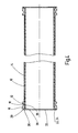
- an inner pipe made of an abrasion-resistant plastic, preferably polyurethane,
- at least one joint element, materially joined to the outside of an end of the inner pipe, the joint element including ring sleeve (appendage, fitting, projection) concentric to the inner pipe and axially extending from a radially projecting collar (flange),
- as well as a reinforcing jacket (casing, envelope) enclosing at least the internal pipe and connected thereto and to the joint element,
- wherein the radially projecting collar of the joint element is defined by a ring-shaped end face and by a thereto joined ring step extending radially towards the inside of the pipe and recessed axially from the ring-shaped end face, and wherein the plastic material of the inner pipe engages in the ring step (22) from the inside of the pipe.
-
- that the ring sleeve of the joint element has an outer surface having an outer diameter which varies in the axial direction,
- and that the reinforcing jacket is formed by a fiber structure tightly wound externally on the inner pipe and the ring sleeve of the joint element, embedded in a plastic matrix, which cooperates form-fittingly, and in certain cases is materially fittingly joined, with the outer surface of the ring sleeve.
-
- that the fiber structure is a fiber cable, fiber tape, fabric tape or mat,
- that the fiber structure contains fiber material selected from carbon fiber, glass fiber, aramide fibers and/or polyester fibers.
- that the fiber structure includes axially laid cross plies and/or radially laid circumferential plies or tiers,
- that the ring sleeve exhibits, running in the axial direction, a wave shape,
- that the ring sleeve exhibits in the axial direction a trapezoid shape, step shape, groove shape or knurled shape,
- that the joint element is provided with pins, and that the fiber structure is laid in the form of loops,
- that the reinforcing jacket and the joint element are bolted together,
- that the two ends of the inner pipe are respectively provided with a joint element with external wave shaped ring sleeves,
- that the ring sleeve of the joint element is tapered on its free end facing away from the collar,
- that the external or outer surface wave contour of the ring sleeve becomes flatter or more shallow towards its free end,
- that the external wave contour exhibits, joining directly axially to the collar, a sharp-edge radial returning wave valley,
- that from the wave valley next to the collar until the free end of the ring sleeve there are formed at least two wave peaks separated from each other by a further wave valley,
- and that the sequential adjacent wave peaks going towards the free end of the ring sleeve exhibit a decreasing radial height.
Claims (17)
Applications Claiming Priority (4)
| Application Number | Priority Date | Filing Date | Title |
|---|---|---|---|
| DE10324321 | 2003-05-27 | ||
| DE10324321.6 | 2003-05-27 | ||
| DE10324321A DE10324321A1 (en) | 2003-05-27 | 2003-05-27 | Delivery pipe for viscous media, in particular, concrete comprises an inner pipe whose material engages with the annular step of the collar element on the inner pipe |
| PCT/EP2004/005163 WO2004111518A1 (en) | 2003-05-27 | 2004-05-14 | Tube for transporting high-viscosity materials |
Publications (2)
| Publication Number | Publication Date |
|---|---|
| US20060054231A1 US20060054231A1 (en) | 2006-03-16 |
| US8074686B2 true US8074686B2 (en) | 2011-12-13 |
Family
ID=33482258
Family Applications (1)
| Application Number | Title | Priority Date | Filing Date |
|---|---|---|---|
| US10/542,730 Expired - Fee Related US8074686B2 (en) | 2003-05-27 | 2004-05-14 | Tube for transporting high-viscosity materials |
Country Status (9)
| Country | Link |
|---|---|
| US (1) | US8074686B2 (en) |
| EP (2) | EP1881254B1 (en) |
| JP (1) | JP2007503563A (en) |
| KR (1) | KR20060015475A (en) |
| CN (1) | CN1759269A (en) |
| AT (2) | ATE388367T1 (en) |
| DE (3) | DE10324321A1 (en) |
| ES (2) | ES2300774T3 (en) |
| WO (1) | WO2004111518A1 (en) |
Cited By (2)
| Publication number | Priority date | Publication date | Assignee | Title |
|---|---|---|---|---|
| US10612716B1 (en) * | 2016-12-15 | 2020-04-07 | United Launch Alliance, L.L.C. | Flexible composite duct for the transport of cryogenic fuels and oxidizers |
| US11174955B2 (en) * | 2017-10-10 | 2021-11-16 | Coperion Gmbh | Diverter valve for conveying a material and method for cleaning thereof |
Families Citing this family (38)
| Publication number | Priority date | Publication date | Assignee | Title |
|---|---|---|---|---|
| CA2460297C (en) * | 2004-02-26 | 2016-01-12 | Industrial Rubber Products, Inc. | Rubber polyurethane liner |
| DE102006007203A1 (en) * | 2006-02-15 | 2007-08-16 | Putzmeister Ag | Composite conveyor tube |
| US9303797B2 (en) * | 2006-07-17 | 2016-04-05 | Gates Corporation | Overmolded standoff and method for abrasion routing protection of a hose |
| CN100436909C (en) * | 2006-10-18 | 2008-11-26 | 大同市东华矿机有限责任公司 | Process for producing double layer concrete transport pipe |
| EP2118550A4 (en) * | 2007-01-22 | 2010-12-08 | John Frederick Olson | Elastomer lined, abrasion resistant pipe and method for manufacture |
| DE102007011041A1 (en) * | 2007-03-07 | 2008-09-11 | Robert Bosch Gmbh | Plastic molded tube |
| DE102007034067B9 (en) * | 2007-07-20 | 2009-05-14 | Arthur Habermann Gmbh & Co. Kg | Ready-mixed concrete plant with polyurethane concrete hose |
| EP2058527A3 (en) * | 2007-11-08 | 2012-05-30 | Parker-Hannifin Corporation | Lightweight high pressure repairable piston composite accumulator with slip flange |
| RU2362942C1 (en) * | 2007-12-27 | 2009-07-27 | Малик Фавзавиевич Гайсин | Flow string (fs) with internal coating eliminating sediments and method for applying this coating |
| FR2926118B1 (en) * | 2008-01-04 | 2010-01-29 | Snecma | COMPOSITE FLANGE WITH MACHINING PART. |
| JP5130104B2 (en) * | 2008-04-17 | 2013-01-30 | 富士重工業株式会社 | Manufacturing method of resin pipe |
| JP5260126B2 (en) * | 2008-04-17 | 2013-08-14 | 富士重工業株式会社 | Resin tube with cap |
| DE102008027233A1 (en) * | 2008-06-06 | 2009-12-10 | Schwing Gmbh | Joint bolt as part of a thick matter pipe |
| IT1401515B1 (en) * | 2010-08-03 | 2013-07-26 | Cifa S P A Unico Socio | PROCEDURE FOR CARRYING OUT A CURVED TUBULAR ELEMENT FOR THE CONVEYANCE OF ABRASIVE MATERIALS SUCH AS CONCRETE, OR SIMILAR, AND CURVED TUBULAR ELEMENT OBTAINED AS FOLLOWS. |
| DE102010034679A1 (en) | 2010-08-18 | 2012-02-23 | Schwing Gmbh | Sludge pump, particularly self-propelled concrete pump, has mast structure with mast arm, at which slurry delivery line is suspended, where slurry delivery line is formed from supply pipes |
| CN101949217B (en) * | 2010-09-27 | 2012-07-25 | 山东德建集团有限公司 | Pump pipe buffer for transmitting concrete |
| CN102052527B (en) * | 2010-12-31 | 2013-01-02 | 三一重工股份有限公司 | End hose of cantilever crane system, preparation method thereof and concrete transporting machine |
| CN102278546B (en) * | 2011-07-19 | 2013-11-13 | 广州海鸥卫浴用品股份有限公司 | Copper plastic compound pipe |
| US20130174935A1 (en) * | 2012-01-10 | 2013-07-11 | II Curtis R. Patterson | Variable thin walled duct with bend |
| ITMI20120973A1 (en) * | 2012-06-05 | 2013-12-06 | Cifa Spa | PIPING FOR ABRASIVE MATERIALS, WHICH CONCRETE OR SIMILAR MATERIALS, AND ITS IMPLEMENTATION PROCEDURE |
| JP6004521B2 (en) * | 2012-07-04 | 2016-10-12 | 臼井国際産業株式会社 | Piping with heat- and corrosion-resistant plating layer with excellent workability |
| JP5592517B2 (en) * | 2013-02-18 | 2014-09-17 | 富士重工業株式会社 | Manufacturing method of resin pipe with cap |
| BE1021201B1 (en) * | 2013-04-15 | 2015-07-28 | C.C. Rombouts Kunststof Techniek Holding B.V. | METHOD FOR COATING, PROTECTING AND REINFORCING PIPES |
| CA2936257C (en) * | 2014-01-08 | 2022-05-31 | Garlock Sealing Technologies, Llc | Wearable rubber parts for fluid handling services including a polyurethane inner layer |
| CN106662276B (en) * | 2014-04-30 | 2020-12-18 | Abc科技股份有限公司 | Air duct with in-mold molded pressure resistant ring |
| EP3137803A4 (en) * | 2014-05-01 | 2018-01-03 | Rampf Composites Solutions Inc. | Multilayer composite waste tube |
| DE102014222563A1 (en) * | 2014-11-05 | 2016-05-12 | Mahle International Gmbh | Method for producing an assembly with a tubular body and a component |
| TR201902637T4 (en) * | 2015-03-20 | 2019-03-21 | Valme S R L Unico Socio | Apparatus and method for producing a pipe for conveying abrasive materials such as concrete. |
| DE102015105830B4 (en) | 2015-04-16 | 2019-05-09 | xperion components GmbH & Co. KG | Method for producing a pressure tube made of a fiber composite material |
| GB2537902A (en) * | 2015-04-30 | 2016-11-02 | M-Flow Tech Ltd | Composite Fluid Conduit Assembly |
| DE202015103065U1 (en) * | 2015-06-11 | 2016-09-14 | Rosen Swiss Ag | Suction dredger segment and suction dredge line |
| DE102016119461A1 (en) * | 2016-10-12 | 2018-04-12 | Esser-Werke Gmbh & Co. Kg | Hybrid pipe with pipe collar and wear ring |
| US11613978B2 (en) * | 2017-03-01 | 2023-03-28 | Fmc Technologies, Inc. | Erosion-resistant inserts for flow equipment |
| CA3055034A1 (en) | 2017-03-01 | 2018-09-07 | Fmc Technologies, Inc. | Erosion-resistant inserts for flow equipment |
| EP3543586B1 (en) * | 2018-03-21 | 2020-10-14 | Esser -Werke GmbH & Co. KG | Hybrid pipe with pipe collar and wear ring and method for producing the same |
| DE202018104584U1 (en) * | 2018-08-09 | 2019-11-20 | Rehau Ag + Co | Rod resistant pipe fitting |
| US11898687B2 (en) * | 2020-08-14 | 2024-02-13 | Ford Global Technologies, Llc | Impact absorber assembly |
| KR102263103B1 (en) * | 2021-03-24 | 2021-06-08 | 이호설 | Method for manufacturing frp flange pipe |
Citations (26)
| Publication number | Priority date | Publication date | Assignee | Title |
|---|---|---|---|---|
| US2219047A (en) | 1939-01-12 | 1940-10-22 | Goodrich Co B F | Hose and coupling structure |
| DE1932448U (en) | 1961-07-22 | 1966-02-10 | Heinrich Dr Ing Klein | PRESSURE RESISTANT TUBE MADE OF THERMOPLASTIC PLASTIC. |
| US3347571A (en) * | 1965-08-30 | 1967-10-17 | Stratoflex Inc | Hose fitting |
| US3462177A (en) * | 1967-07-31 | 1969-08-19 | Hewitt Robins Inc | Flexible hose and coupling therefor |
| US3537484A (en) * | 1968-11-29 | 1970-11-03 | Universal Oil Prod Co | Filament-wound pipe |
| US3613736A (en) * | 1968-12-04 | 1971-10-19 | Bridgestone Tire Co Ltd | Stranded wire reinforced fluid transporting hose |
| US3742985A (en) * | 1967-01-31 | 1973-07-03 | Chemstress Ind Inc | Reinforced pipe |
| FR2197140A1 (en) * | 1972-08-25 | 1974-03-22 | Oldham Seals Ltd | |
| GB1396119A (en) | 1972-09-18 | 1975-06-04 | Schwarz W | Pipe joint |
| DE2419898A1 (en) * | 1974-04-22 | 1975-10-30 | Mannesmann Export Ag | Hydraulic or pneumatic conveyor tube - has hard-wearing plastic lining tubes sliding in sleeves of same material |
| US4142554A (en) * | 1977-10-28 | 1979-03-06 | Parker-Hannifin Corporation | Hose construction |
| US4267863A (en) | 1974-11-19 | 1981-05-19 | Compagnie Plastic Omnium | Tube reinforced with a synthetic material |
| US4366842A (en) | 1980-08-27 | 1983-01-04 | The Goodyear Tire & Rubber Company | Flanged hose and method of making |
| EP0266810A2 (en) * | 1986-10-24 | 1988-05-11 | Pumptech N.V. | System for the assembly of a metal joining-piece and a high-pressure composite material tube - notably applications for equipment used in the oil industry |
| US4995427A (en) * | 1988-06-30 | 1991-02-26 | Metalpraecis Berchem & Schaberg Gesellschaft Fur Metallformgebung Mit Beschrankter Haftung | Pipe section, especially for abrasive and/or corrosive material pipelines |
| US5255944A (en) * | 1991-05-30 | 1993-10-26 | Hutchinson | Coupler for a textile-reinforced rubber hose |
| US5368669A (en) * | 1992-02-27 | 1994-11-29 | British Gas Plc | Method of lining a pipeline |
| DE19522540A1 (en) * | 1994-06-23 | 1996-01-04 | Forms Const | Pipe unit in concrete delivery line |
| US5573282A (en) * | 1995-02-16 | 1996-11-12 | United Pipeline System, Usa, Inc. | Low turbulence joint for lined slurry pipeline |
| DE19821637A1 (en) * | 1998-05-14 | 1999-11-18 | Esser Werke Gmbh & Co Kg | Pipeline transporting abrasive substances incorporates detector |
| DE19914668A1 (en) * | 1999-03-31 | 2000-11-02 | Da Kunstoff Gmbh | Flanged pipe comprises a flange section with an outer ring zone which is provided with axial protrusions whose faces rest against the flange surface of the other pipe |
| US6155302A (en) * | 1996-01-27 | 2000-12-05 | Robert Bosch Gmbh | Fastening device for attaching a fuel line to a connecting piece |
| DE10143187C1 (en) | 2001-09-04 | 2003-04-17 | Esser Werke Kg | Double-layer pipe for the fluid transport of abrasive substances |
| US20030205898A1 (en) * | 2002-05-03 | 2003-11-06 | Baldwin Gardner T. | High pressure reinforced rubber hose swage or crimped coupling and method of attachment |
| US20050093293A1 (en) * | 2002-04-11 | 2005-05-05 | Festo Ag & Co. | Fluid operated contractile drive |
| US20070157443A1 (en) * | 2003-05-02 | 2007-07-12 | Baldwin Gardner T | Method of attachment for a high pressure reinforced rubber hose coupling |
-
2003
- 2003-05-27 DE DE10324321A patent/DE10324321A1/en not_active Withdrawn
-
2004
- 2004-05-14 AT AT04732960T patent/ATE388367T1/en not_active IP Right Cessation
- 2004-05-14 ES ES04732960T patent/ES2300774T3/en active Active
- 2004-05-14 ES ES07119140T patent/ES2317626T3/en active Active
- 2004-05-14 US US10/542,730 patent/US8074686B2/en not_active Expired - Fee Related
- 2004-05-14 KR KR1020057017303A patent/KR20060015475A/en not_active Application Discontinuation
- 2004-05-14 DE DE502004008610T patent/DE502004008610D1/en active Active
- 2004-05-14 EP EP07119140A patent/EP1881254B1/en not_active Not-in-force
- 2004-05-14 DE DE502004006419T patent/DE502004006419D1/en active Active
- 2004-05-14 CN CNA2004800062816A patent/CN1759269A/en active Pending
- 2004-05-14 WO PCT/EP2004/005163 patent/WO2004111518A1/en active IP Right Grant
- 2004-05-14 EP EP04732960A patent/EP1627176B8/en active Active
- 2004-05-14 JP JP2006529812A patent/JP2007503563A/en not_active Withdrawn
- 2004-05-14 AT AT07119140T patent/ATE416340T1/en not_active IP Right Cessation
Patent Citations (26)
| Publication number | Priority date | Publication date | Assignee | Title |
|---|---|---|---|---|
| US2219047A (en) | 1939-01-12 | 1940-10-22 | Goodrich Co B F | Hose and coupling structure |
| DE1932448U (en) | 1961-07-22 | 1966-02-10 | Heinrich Dr Ing Klein | PRESSURE RESISTANT TUBE MADE OF THERMOPLASTIC PLASTIC. |
| US3347571A (en) * | 1965-08-30 | 1967-10-17 | Stratoflex Inc | Hose fitting |
| US3742985A (en) * | 1967-01-31 | 1973-07-03 | Chemstress Ind Inc | Reinforced pipe |
| US3462177A (en) * | 1967-07-31 | 1969-08-19 | Hewitt Robins Inc | Flexible hose and coupling therefor |
| US3537484A (en) * | 1968-11-29 | 1970-11-03 | Universal Oil Prod Co | Filament-wound pipe |
| US3613736A (en) * | 1968-12-04 | 1971-10-19 | Bridgestone Tire Co Ltd | Stranded wire reinforced fluid transporting hose |
| FR2197140A1 (en) * | 1972-08-25 | 1974-03-22 | Oldham Seals Ltd | |
| GB1396119A (en) | 1972-09-18 | 1975-06-04 | Schwarz W | Pipe joint |
| DE2419898A1 (en) * | 1974-04-22 | 1975-10-30 | Mannesmann Export Ag | Hydraulic or pneumatic conveyor tube - has hard-wearing plastic lining tubes sliding in sleeves of same material |
| US4267863A (en) | 1974-11-19 | 1981-05-19 | Compagnie Plastic Omnium | Tube reinforced with a synthetic material |
| US4142554A (en) * | 1977-10-28 | 1979-03-06 | Parker-Hannifin Corporation | Hose construction |
| US4366842A (en) | 1980-08-27 | 1983-01-04 | The Goodyear Tire & Rubber Company | Flanged hose and method of making |
| EP0266810A2 (en) * | 1986-10-24 | 1988-05-11 | Pumptech N.V. | System for the assembly of a metal joining-piece and a high-pressure composite material tube - notably applications for equipment used in the oil industry |
| US4995427A (en) * | 1988-06-30 | 1991-02-26 | Metalpraecis Berchem & Schaberg Gesellschaft Fur Metallformgebung Mit Beschrankter Haftung | Pipe section, especially for abrasive and/or corrosive material pipelines |
| US5255944A (en) * | 1991-05-30 | 1993-10-26 | Hutchinson | Coupler for a textile-reinforced rubber hose |
| US5368669A (en) * | 1992-02-27 | 1994-11-29 | British Gas Plc | Method of lining a pipeline |
| DE19522540A1 (en) * | 1994-06-23 | 1996-01-04 | Forms Const | Pipe unit in concrete delivery line |
| US5573282A (en) * | 1995-02-16 | 1996-11-12 | United Pipeline System, Usa, Inc. | Low turbulence joint for lined slurry pipeline |
| US6155302A (en) * | 1996-01-27 | 2000-12-05 | Robert Bosch Gmbh | Fastening device for attaching a fuel line to a connecting piece |
| DE19821637A1 (en) * | 1998-05-14 | 1999-11-18 | Esser Werke Gmbh & Co Kg | Pipeline transporting abrasive substances incorporates detector |
| DE19914668A1 (en) * | 1999-03-31 | 2000-11-02 | Da Kunstoff Gmbh | Flanged pipe comprises a flange section with an outer ring zone which is provided with axial protrusions whose faces rest against the flange surface of the other pipe |
| DE10143187C1 (en) | 2001-09-04 | 2003-04-17 | Esser Werke Kg | Double-layer pipe for the fluid transport of abrasive substances |
| US20050093293A1 (en) * | 2002-04-11 | 2005-05-05 | Festo Ag & Co. | Fluid operated contractile drive |
| US20030205898A1 (en) * | 2002-05-03 | 2003-11-06 | Baldwin Gardner T. | High pressure reinforced rubber hose swage or crimped coupling and method of attachment |
| US20070157443A1 (en) * | 2003-05-02 | 2007-07-12 | Baldwin Gardner T | Method of attachment for a high pressure reinforced rubber hose coupling |
Cited By (2)
| Publication number | Priority date | Publication date | Assignee | Title |
|---|---|---|---|---|
| US10612716B1 (en) * | 2016-12-15 | 2020-04-07 | United Launch Alliance, L.L.C. | Flexible composite duct for the transport of cryogenic fuels and oxidizers |
| US11174955B2 (en) * | 2017-10-10 | 2021-11-16 | Coperion Gmbh | Diverter valve for conveying a material and method for cleaning thereof |
Also Published As
| Publication number | Publication date |
|---|---|
| KR20060015475A (en) | 2006-02-17 |
| EP1627176B8 (en) | 2008-05-21 |
| ES2300774T3 (en) | 2008-06-16 |
| EP1881254B1 (en) | 2008-12-03 |
| DE10324321A1 (en) | 2004-12-23 |
| DE502004008610D1 (en) | 2009-01-15 |
| EP1881254A1 (en) | 2008-01-23 |
| ES2317626T3 (en) | 2009-04-16 |
| DE502004006419D1 (en) | 2008-04-17 |
| CN1759269A (en) | 2006-04-12 |
| WO2004111518A1 (en) | 2004-12-23 |
| JP2007503563A (en) | 2007-02-22 |
| ATE416340T1 (en) | 2008-12-15 |
| ATE388367T1 (en) | 2008-03-15 |
| EP1627176A1 (en) | 2006-02-22 |
| EP1627176B1 (en) | 2008-03-05 |
| US20060054231A1 (en) | 2006-03-16 |
Similar Documents
| Publication | Publication Date | Title |
|---|---|---|
| US8074686B2 (en) | Tube for transporting high-viscosity materials | |
| RU2121101C1 (en) | Pipe and method of its manufacture | |
| US3989280A (en) | Pipe joint | |
| JP2007503563A5 (en) | ||
| US4106797A (en) | Reinforced fitting construction | |
| US4329193A (en) | Method of making a coupling for rigid pressure pipe | |
| CN109555909B (en) | Double-wall inner rib glass fiber reinforced plastic sandwich concrete high-strength composite pipeline and processing method thereof | |
| CN110486568B (en) | Pretightening force repairing method, pretightening force and clamp combined repairing method and repaired pipeline | |
| US3572392A (en) | Threaded filament wound pipe and the method of manufacture thereof | |
| US4353581A (en) | Hose coupling | |
| US3717180A (en) | Flexible hose | |
| US11098837B2 (en) | Fitting element for use in rehabilitation of pipelines and method for producing the same | |
| CA1167788A (en) | Flanged hose | |
| FI105414B (en) | Procedure for laying underwater pipelines in deep water | |
| US4319950A (en) | Mandrel for making a coupling for rigid pressure pipe | |
| US4654096A (en) | Method of making a flexible hose | |
| CA1108071A (en) | Composite pipe having an integral bell end | |
| RU2201550C2 (en) | Composite-material branch pipe and its manufacturing process | |
| GB2125505A (en) | Hose fitting | |
| JP7406603B2 (en) | curved pipe | |
| RU2451859C2 (en) | Glass-plastic aggressive resistant tube and method for manufacturing it | |
| EP0253604A1 (en) | Intersticed nipple for elastomeric hoses and method | |
| CN115468060A (en) | Flexible composite pipeline leakage stopping method | |
| RU2098709C1 (en) | Combined high-pressure pipe | |
| CN113958775A (en) | Multi-layer liner, catheter system and method of manufacture |
Legal Events
| Date | Code | Title | Description |
|---|---|---|---|
| AS | Assignment |
Owner name: PUTZMEISTER AKTIENGESELLSCHAFT, GERMANY Free format text: ASSIGNMENT OF ASSIGNORS INTEREST;ASSIGNORS:WOLFRAM, DR. MARKUS;KASTEN, KNUT;MUELLER, DR. DIETMAR;AND OTHERS;SIGNING DATES FROM 20050603 TO 20050621;REEL/FRAME:018020/0212 Owner name: PUTZMEISTER AKTIENGESELLSCHAFT, GERMANY Free format text: ASSIGNMENT OF ASSIGNORS INTEREST;ASSIGNORS:WOLFRAM, DR. MARKUS;KASTEN, KNUT;MUELLER, DR. DIETMAR;AND OTHERS;REEL/FRAME:018020/0212;SIGNING DATES FROM 20050603 TO 20050621 |
|
| AS | Assignment |
Owner name: PUTZMEISTER CONCRETE PUMPS GMBH, GERMANY Free format text: CHANGE OF NAME;ASSIGNOR:PUTZMEISTER ATIENGESELLSCHAFT;REEL/FRAME:021328/0506 Effective date: 20080425 Owner name: PUTZMEISTER CONCRETE PUMPS GMBH,GERMANY Free format text: CHANGE OF NAME;ASSIGNOR:PUTZMEISTER ATIENGESELLSCHAFT;REEL/FRAME:021328/0506 Effective date: 20080425 |
|
| AS | Assignment |
Owner name: PUTZMEISTER CONCRETE PUMPS GMBH,GERMANY Free format text: RE-RECORD TO CORRECT CONVEYING/RECEIVING PARTY, PREVIOUSLY RECORDED AT REEL/FRAME 021328/0506;ASSIGNOR:PUTZMEISTER AKTIENGESELLSCHAFT;REEL/FRAME:023892/0382 Effective date: 20080425 Owner name: PUTZMEISTER CONCRETE PUMPS GMBH, GERMANY Free format text: RE-RECORD TO CORRECT CONVEYING/RECEIVING PARTY, PREVIOUSLY RECORDED AT REEL/FRAME 021328/0506;ASSIGNOR:PUTZMEISTER AKTIENGESELLSCHAFT;REEL/FRAME:023892/0382 Effective date: 20080425 |
|
| ZAAA | Notice of allowance and fees due |
Free format text: ORIGINAL CODE: NOA |
|
| ZAAB | Notice of allowance mailed |
Free format text: ORIGINAL CODE: MN/=. |
|
| AS | Assignment |
Owner name: XPERION GMBH, GERMANY Free format text: ASSIGNMENT OF ASSIGNORS INTEREST;ASSIGNOR:PUTZMEISTER CONCRETE PUMPS GMBH;REEL/FRAME:027181/0627 Effective date: 20100810 |
|
| STCF | Information on status: patent grant |
Free format text: PATENTED CASE |
|
| FPAY | Fee payment |
Year of fee payment: 4 |
|
| MAFP | Maintenance fee payment |
Free format text: PAYMENT OF MAINTENANCE FEE, 8TH YEAR, LARGE ENTITY (ORIGINAL EVENT CODE: M1552); ENTITY STATUS OF PATENT OWNER: LARGE ENTITY Year of fee payment: 8 |
|
| FEPP | Fee payment procedure |
Free format text: MAINTENANCE FEE REMINDER MAILED (ORIGINAL EVENT CODE: REM.); ENTITY STATUS OF PATENT OWNER: LARGE ENTITY |
|
| LAPS | Lapse for failure to pay maintenance fees |
Free format text: PATENT EXPIRED FOR FAILURE TO PAY MAINTENANCE FEES (ORIGINAL EVENT CODE: EXP.); ENTITY STATUS OF PATENT OWNER: LARGE ENTITY |
|
| STCH | Information on status: patent discontinuation |
Free format text: PATENT EXPIRED DUE TO NONPAYMENT OF MAINTENANCE FEES UNDER 37 CFR 1.362 |
|
| FP | Lapsed due to failure to pay maintenance fee |
Effective date: 20231213 |