US8074812B1 - Rotary track mechanism for corner cabinets - Google Patents
Rotary track mechanism for corner cabinets Download PDFInfo
- Publication number
- US8074812B1 US8074812B1 US12/655,727 US65572710A US8074812B1 US 8074812 B1 US8074812 B1 US 8074812B1 US 65572710 A US65572710 A US 65572710A US 8074812 B1 US8074812 B1 US 8074812B1
- Authority
- US
- United States
- Prior art keywords
- track
- hanger
- hanging
- assembly
- door
- Prior art date
- Legal status (The legal status is an assumption and is not a legal conclusion. Google has not performed a legal analysis and makes no representation as to the accuracy of the status listed.)
- Expired - Fee Related
Links
Images


Classifications
-
- A—HUMAN NECESSITIES
- A47—FURNITURE; DOMESTIC ARTICLES OR APPLIANCES; COFFEE MILLS; SPICE MILLS; SUCTION CLEANERS IN GENERAL
- A47B—TABLES; DESKS; OFFICE FURNITURE; CABINETS; DRAWERS; GENERAL DETAILS OF FURNITURE
- A47B49/00—Revolving cabinets or racks; Cabinets or racks with revolving parts
- A47B49/004—Cabinets with compartments provided with trays revolving on a vertical axis
- A47B49/006—Corner cabinets
Definitions
- Teflon used in this manner has one major drawback, it is fragile and susceptible to damage from contact with metal utensils or the metal from other pots and pans. Teflon coated cookware also has exposed metal bottoms, sides and handles which when stacked upon each other inside of corner cabinets causes the damaging contact that can cause the Teflon to peal from the cooking surface thus eliminating Teflon as an advantage to the cookware.
- FIG. 1 is a top view of the cookware and utensil hanging assembly for corner cabinets with a lower circular shelf.
- FIG. 2 is a cross-section view from FIG. 1 detailing the hanging track and hanging assembly.
- FIG. 3 is a cross-section view from FIG. 1 detailing the hanging track and hanging guard assembly.
- FIG. 6 is a top view of the cookware and utensil hanging assembly for corner cabinets including the circular shelf and the hanging track is not attached to the cabinet door.
- FIG. 3 is a side view of the hanging guard assembly 11 , hanger assembly 10 , and hanging track 4 .
- Clamp 5 attaches and supports track 4 to track support 6 .
- Track 4 supports the hanger assembly 10 through track slot 14 by a ball end 13 .
- Hanger assembly 10 supports hanging guard assembly 11 from hanger assembly hook end 15 .
- Hanging guard assembly 11 consists of hanging protector assembly hook 17 connected to hanging protector assembly main shaft 23 that is connected to hanging protector assembly shoulder 18 .
- Shoulder 18 supports hanging protector assembly guards 19 which support hanging protector assembly guard ends 20 .
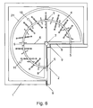
- FIG. 5 is a bottom view of the rotary track mechanism for corner cabinets.
- a corner cabinet 1 and cabinet door 2 contains the hanging assembly.
- Brackets 3 connect the track 4 to door 2 .
- Clamps 5 attach the track 4 to track supports 6 that are attached to shaft 7 , all of which with brackets 3 support the weight of the assembly and the items that are hung from the hanging assembly.
- Hanging track channel closure 8 allows for the addition or removal of hanger assemblies 10 from track 4 .
- Hanger assemblies 10 and hanging guard assemblies 11 are supported from the hanging track 4 through track slot 14 .
- FIG. 1 is a top view
- FIG. 4 is a side view
- FIG. 5 is a bottom view of the rotary track mechanism for corner cabinets.
- Track 4 is connected to track clamps 5 which are connected to track supports 6 which are suspended by center shaft 7 inside of a corner cabinet 1 .
- Center shaft brackets 12 supports shaft 7 in a vertical position inside of cabinet 1 .
- Track brackets 3 also support track 4 by connecting track 4 to cabinet door 2 .
- the cookware and utensil hanging assembly for corner cabinets, circular shelf 21 , and cabinet door 2 are able to rotate 360° around the axis formed by shaft 7 .
- Hanger assemblies 10 are supported by track 4 through track slot 14 and are capable of changing position anywhere along track 4 except for where another assembly is already in position.
Abstract
A rotary hanging track storage unit for mounting in a corner cabinet includes a circular hanging track 4 and hanger assemblies 10, hanging guard assemblies 11, and hanger extensions 22. The track 7 is attached to and supported by hanging track brackets 3, hanging track clamps 5, track supports 6, and center shaft 7. The assembly can be rotated within the corner cabinet 2 where cookware and utensils can be hung from assemblies 10 and extensions 22 to be accessed and stored.
Description
This application claims the benefit of PPA Ser. No. 61/216,431 filed 2009 May 18
None
None
This invention relates to cookware and utensil storage hangers, more specifically storage hangers that utilize the space inside of kitchen corner cabinets.
Kitchen corner cabinet cookware and utensil storage has always been awkward, inefficient, and cumbersome. The problem of storing several different sized and shaped cookware and utensils inside corner cabinets has made their storage nearly impossible to do in a manner that is satisfactory for anyone who desires a neat and efficient kitchen. The problem of cookware storage has been compounded over the recent decades by the introduction and ubiquitous adaptation of non-stick cookware. This style of cookware utilizes Teflon as a non-stick surface between the cookware's metal surface and the food being cooked allowing the food to be easily removed from the cookware and ease in it's cleaning. Teflon used in this manner has one major drawback, it is fragile and susceptible to damage from contact with metal utensils or the metal from other pots and pans. Teflon coated cookware also has exposed metal bottoms, sides and handles which when stacked upon each other inside of corner cabinets causes the damaging contact that can cause the Teflon to peal from the cooking surface thus eliminating Teflon as an advantage to the cookware.
One method of safe guarding the Teflon coating of non-stick cookware would be to not stack the cookware in a manner that would allow metal to Teflon contact. This method of in cabinet storage would be an inefficient use of cabinet space, as each piece of cookware would need its own shelf area on the cabinet's shelves. Another alternative would be the use of a hanging cookware rack which would be mounted from the ceiling and hang in the kitchen exposed in the kitchen's open area. This method of cookware storage would leave the cookware exposed as well as consuming space in the kitchen that could be used for other purposes when the cookware is not needed. Cookware hanging in the kitchen and can be also an unsightly eyesore and consume kitchen open space.
There have been several attempts in the past to help lesson the problem of kitchen cookware and utensil cabinet storage but none have so far been satisfactory for conveniently and neatly store these items.
There have been many attempts in the past to solve the problem of cookware and utensil storage in kitchens, and these attempts can be categorized into several types of devices invented.
The most popular device utilized for cookware and utensil storage is the hanging storage rack. These types of racks are most popular in larger kitchens where they can be hung in the open space of the kitchen thus taking up useful kitchen workspace. The cookware is also exposed creating an eyesore for most who desire a neat and clean kitchen. Most of these racks have been issued a Design patent since these racks have little or no unique features to produce unexpected results to warrant a Utility patent. Other attempts include pull out racks that are installed inside of cabinets or closets. While these types of racks are clever attempt to solve the cookware storage problem these racks tend to be complicated and thus expensive and difficult to install.
U.S. Pat. No. 2,758,904 issued May 28, 1954 to Hansell describes a pull out pan rack but unfortunately the product suffers from many shortcomings as a simple and functional solution to the cookware storage problem. Hansell's rack would slide in and out of the cabinet space, the rack itself constructed from pegboard or the like. The hanger is cumbersome in construction and installation and is not adjustable in size therefore could not universally fit different sized cabinets. The hooks are also only adjustable in which the positions the user had placed them prior to hanging utensils.
U.S. Pat. No. 3,198,594 issued to Murray Jul. 3, 1963 details a lazy susan style rotary rack. Murray specifies a rotating rack system that has two rotating shelves that are able to rotate independent of each other and does not require a center post. While these features may be beneficial compared to other lazy susan cabinet designs Murray's invention still utilizes shelves as the main means for storage for his cabinet storage solution. The use of shelves exclusively for storage will lend itself to an inefficient method for storage for cookware as the cookware would need to be stacked to save cabinet space or each piece of cookware would need its own shelf space thus consuming storage space in an inefficient manner.
Another method of cookware storage that incorporates the use of pull out cabinet racks is U.S. Pat. No. 3,379,484 issued April 1968 to Kilng. This patent details a pivoted rack for utensils and the like, which incorporates sheets of pegboard that can be swung outside of the cabinet storage space. Unfortunately this rack would not be functional in a cabinet that had a divider between the cabinet doors, and the hooks are only adjustable in which the positions the user had placed them prior to hanging utensils. The hanger is also cumbersome in construction and installation and is not adjustable in size therefore could not universally fit different sized cabinets.
U.S. Pat. No. 3,780,875 issued December 1973 to Scholl details a suspended hanger for pots and pans from an overhead surface. The device utilizes a base member and a column and a hanger assembly secured to the lower end of the column that rotates around the column. The hanger would be unable to fit inside of a conventional kitchen cabinet, as it would require a large vertically symmetric area for operating the rotational hanger feature of the device. The individual hangers cannot be independently positioned in relation to the other hangers therefore the entire device must be rotated in order to reposition the cookware.
U.S. Pat. No. 4,290,531 issued Sep. 22, 1981 to Lazarus details a device for holding cooking pots and lids. The device does hang pots and lids but fails to have adjustable or moveable hooks and the hooks must work in concert with lid holders to suspend both pots and lids.
U.S. Pat. No. 4,714,166 issued Dec. 22, 1987 to Hann and Fuller details a supporting rack for cooking utensils. The rack has a framed structure that supports several hooks along its framed perimeter. The rack was intended to hang from the kitchen ceiling or from another structure providing enough structural strength and area to hang the rack and the cookware hung by it. The hooks are only able to slide along the framed perimeter and are unable to pivot and rotate. This device was envisioned for use in an open area of the kitchen and not inside of a closed structure like a cabinet.
U.S. Pat. No. 5,238,127 issued Aug. 24, 1993 to Geller details a pan holder that is attached to the ceiling and stores pans in an overhead position near the end of a flexible cantilever beam which can be pulled down to allow easy removal of the pots and pans. The holder does not however allow for adjustable hooks whereby the hooks can be moved into different positions along the holder as well as not being able to pivot and rotate. The holder is intended for use in the open kitchen area and not compatible for use in a closed area such as a cabinet.
U.S. Pat. No. 5,249,856 issued to Dreier on Oct. 5, 1993 details a corner cupboard employing the usual rotating shelves as does other corner cupboards but Dreier's patent specifies a center shaft that does not need to be journalled or guided at the top. This configuration serves the purpose of having a top shelf whose top plane is not interrupted buy the intrusion of a center shaft thus allowing for a more efficient use of the top shelf. Dreier's invention unfortunately still relies upon shelves as the storage method which is inherently inefficient for the storage of cookware as the cookware would have to either be stacked to save the surface space of the shelves or each piece of cookware has its own space for storage upon the shelf thus consuming the surface space of the shelf in an inefficient manner.
U.S. Pat. No. 6,039,191 issued Jul. 2, 1997 to Purnell also details a hanging rack for being suspended from the ceiling in the open kitchen area. This structure is complicated in construction that results in a large, heavy, and expensive device for hanging cookware and utensils. The devices utilizes a plurality of bars from which it is to be hung from and hooks which are able to slide along the bars but unable to pivot and rotate.
Another attempt to solve the kitchen cookware and utensil storage problem is the introduction of pull out hanging racks. U.S. Pat. No. 6,227,387 issued May 8, 2001 to Rose details an apparatus for supporting utensils. Rose's design allows for the rack to be pulled out of the cabinet from it's supporting base, which would be mounted inside of a cabinet. Rose's design unfortunately does not allow for adjustable hooks. Rose's hooks are fixed to one piece thus not allowing for independent positioning of the hooks as well as his hooks cannot rotate and pivot. Rose's design also would make multiple cookware placement cumbersome since different pieces of cookware have different dimensions and would require different hook interval positions for each piece of cookware. Rose's sound accentuating feature would also make hanging and retrieving cookware less convenient since each one would be between adjacent cookware and thus become an obstacle to one using Rose's device.
Another method of storing cookware in a cabinet is the use of wire storage racks inside of the cabinet. U.S. Pat. No. 6,729,479 issued to Morgan on May 4, 2004 details a wire storage rack for pots and pans that can be mounted on a base. This style of storage device is unfortunately inconvenient in use since it requires the user to navigate the wires with cookware in it's storage in order to store the piece of cookware in hand. The device also uses the base of the cabinet instead of being able to hang from an overhead plane thus consuming the base of the cabinet's storage area while not offering more storage volume than a hanging device.
Another pull out hanging rack was patented U.S. Pat. No. 6,976,595 by Geller on Dec. 20, 2005. Geller's patent unfortunately suffers from some of the same shortcomings as Rose's patent in that the hooks remain stationary and therefore does not allow the assembly to fully accommodate the user's need for adjustability for storing and retrieving varying sized and shaped cookware. Geller's and Rose's assemblies would also require a cabinet space which is deep in length from front to back to accommodate a pull out rack of this nature, something rarely seen in any kitchen as most cabinets are wider than they are long.
U.S. Pat. Nos. 7,104,409, 7,121,413, and 7,007,808 all detail wire storage racks of similar configuration as Morgan's patent, and all unfortunately all suffer from the same short comings as Morgan's patent as they are all complicated in construction and use.
The advantages of the in cabinet kitchen cookware hanger are as follows:
-
- (a) to provide a more efficient method to utilize the storage volume inside of a kitchen corner cabinet for cookware and utensil storage;
- (b) to provide a more efficient and convenient method of cookware and utensil storage and retrieval during kitchen operation;
- (c) to provide an improved method of cookware and utensil organization;
- (d) to provide a cookware storage solution for fragile Teflon coated cookware from the damage that could occur if the cookware was to be stored in with conventional methods;
- (e) to provide adjustable hanger assemblies to accommodate varying sizes of storage areas in which the assemblies would be installed.
- Further objects and advantages of my invention will become apparent from a consideration of the drawings and ensuing description.
The rotary track mechanism for corner cabinets is an assembly for hanging implements with accommodating appendages inside the confines of a corner cabinet. The rotary track mechanism is primarily a circular track that is attached to a central vertical shaft that is anchored centrally inside of a corner cabinet. The circular track would support hanger assemblies whose positions are adjustable along the length of the circular track, the hanger assemblies have hooks which hang in a downward vertical position that can rotate and pivot on their vertical axis from the hanger assemblies.
-
- 1. Corner cabinet
- 2. Cabinet door
- 3. Hanging track bracket
- 4. Hanging track
- 5. Hanging track clamp
- 6. Hanging track support
- 7. Center shaft
- 8. Hanging track channel closure
- 9. Cabinet door hinge
- 10. Hanger assembly
- 11. Hanging guard assembly
- 12. Center shaft bracket
- 13. Hanger assembly ball end
- 14. Track Slot
- 15. Hanger assembly hook end
- 16. Hanger assembly hook shaft
- 17. Hanging protector assembly hook
- 18. Hanging protector assembly shoulder
- 19. Hanging protector assembly guard
- 20. Hanging protector assembly guard end
- 21. Circular Shelf
- 22. Hanger extension
- 23. Hanging protector assembly main shaft
- 24. Cabinet door hinge
Claims (4)
1. A rotary track mechanism for suspending articles within a corner cabinet having an interior with an interior top surface and interior bottom surface and a door, the rotary track mechanism comprising:
a) a central vertical shaft positioned in the interior of the corner cabinet for rotation therein;
b) first and second shaft brackets spaced apart and opposing each other, the first shaft bracket mounted on the interior top surface and the second shaft bracket mounted on the interior bottom surface of the corner cabinet, the vertical shaft having first and second ends disposed at lengthwise between the first and second shaft brackets, the shaft forms a vertical rotatable axis;
c) a circular track; wherein said circular track is configured to accept and be attached to the interior of the cabinet door of said corner cabinet whereby the door also partially bears the weight of said circular track and whereby both the door and said rotary track mechanism are able to rotate in unison;
d) a plurality of track supports; wherein each of the track supports having ends connected to the vertical shaft and the circular track respectively;
e) a plurality of hanger assemblies coupled to the circular track, the positions of said hanger assemblies are adjustable along the length of said circular track, and wherein each of the hanger assembly comprising: a pivoting mechanism configured to allow said hanger assemblies to pivot and rotate a predetermined number of degrees from the circular track, and a hooking mechanism configured to hold articles in a vertical position; and
f) hanging guard assemblies suspended vertically from the hanger assemblies, each hanging guard assembly comprising an elongated shoulder having guards extending downwardly therefrom to protect said articles from contact with each other during rotation of the hanger assemblies or when the articles are moved.
2. The article from claim 1 further including a circular shelf attached to said shaft, said shelf is positioned below said circular track and said shelf is configured to accept and be attached to the inside of said door whereby said shelf, said door, and said rotary track mechanism are able to rotate together.
3. The article from claim 1 further including at least one hanger extension, said hanger extension is attachable to said hanger assembly and said hanger extension is configured to hold an accommodating article in a downward vertical position whereby said hanger extension increases the distance from which said articles hang from said rotary track mechanism.
4. The article from claim 3 further including a circular shelf attached to said shaft, said shelf is positioned below said circular track and said shelf is configured to accept and be attached to the inside of said door whereby said shelf, said door, and said rotary track mechanism are able to rotate together.
Priority Applications (1)
| Application Number | Priority Date | Filing Date | Title |
|---|---|---|---|
| US12/655,727 US8074812B1 (en) | 2009-05-18 | 2010-01-06 | Rotary track mechanism for corner cabinets |
Applications Claiming Priority (2)
| Application Number | Priority Date | Filing Date | Title |
|---|---|---|---|
| US21643109P | 2009-05-18 | 2009-05-18 | |
| US12/655,727 US8074812B1 (en) | 2009-05-18 | 2010-01-06 | Rotary track mechanism for corner cabinets |
Publications (1)
| Publication Number | Publication Date |
|---|---|
| US8074812B1 true US8074812B1 (en) | 2011-12-13 |
Family
ID=45092577
Family Applications (1)
| Application Number | Title | Priority Date | Filing Date |
|---|---|---|---|
| US12/655,727 Expired - Fee Related US8074812B1 (en) | 2009-05-18 | 2010-01-06 | Rotary track mechanism for corner cabinets |
Country Status (1)
| Country | Link |
|---|---|
| US (1) | US8074812B1 (en) |
Cited By (8)
| Publication number | Priority date | Publication date | Assignee | Title |
|---|---|---|---|---|
| US9022237B2 (en) | 2013-05-22 | 2015-05-05 | Glideware, Llc. | Extendable storage device |
| US20150189987A1 (en) * | 2014-01-03 | 2015-07-09 | Robert Barnes Louthan, JR. | Rigging tree |
| FR3017035A1 (en) * | 2014-02-04 | 2015-08-07 | Isabelle Celine Guedra | DEVICE FOR OPTIMIZING THE USE OF ANGLES IN LAUNDRY STORAGE CABINETS AND SPACE IN PARTS WHERE THEY ARE LOCATED |
| US9254050B1 (en) * | 2013-10-22 | 2016-02-09 | Michael S. Bradbury | Detachable hanging assembly for cookware and utensils |
| US9427082B2 (en) | 2015-01-14 | 2016-08-30 | Cabinet Storage Solutions, Inc. | Rotating storage cabinet for corner installation |
| WO2017066542A1 (en) * | 2015-10-15 | 2017-04-20 | Glideware Llc | Rotatable storage device |
| US10986942B2 (en) * | 2018-11-28 | 2021-04-27 | Holland J. Wood | Configurable storage system |
| US11147404B1 (en) * | 2020-08-18 | 2021-10-19 | James Duffy | Garment organizer assembly |
Citations (19)
| Publication number | Priority date | Publication date | Assignee | Title |
|---|---|---|---|---|
| US877751A (en) * | 1907-07-08 | 1908-01-28 | James M Acheson | Display-cabinet. |
| US1132190A (en) * | 1914-02-03 | 1915-03-16 | Emanuel G Kohout | Garment-hanger. |
| US1255584A (en) * | 1915-01-07 | 1918-02-05 | George S Gritman | Garment-display fixture. |
| US2611492A (en) * | 1948-10-19 | 1952-09-23 | Ivor B Watts | Hanger in strip form |
| US2758904A (en) | 1954-05-28 | 1956-08-14 | Brammer Mfg Company | Pan rack assembly |
| US3175243A (en) * | 1962-09-10 | 1965-03-30 | Beer Hans | Curtain suspension glider and hook |
| US3198594A (en) | 1963-07-03 | 1965-08-03 | Hilton B Murray | Rotary storage rack |
| US3379484A (en) | 1966-08-05 | 1968-04-23 | Ralph C. Kling | Pivoted rack for utensils and the like |
| US3780875A (en) * | 1972-06-14 | 1973-12-25 | L Scholl | Suspended hanger |
| US3982800A (en) * | 1976-02-23 | 1976-09-28 | Ajax Hardware Corporation | Rotary-position catch for rotatable corner shelf units |
| US4290531A (en) * | 1979-10-15 | 1981-09-22 | Lazarus Iii Fred | Device for holding cooking pots and lids |
| US4714166A (en) | 1985-04-03 | 1987-12-22 | Commercial Aluminum Cookware Company | Supporting rack for cooking utensils |
| US5238127A (en) | 1992-03-02 | 1993-08-24 | Geller Edward W | Pan holder |
| US5249856A (en) | 1990-03-21 | 1993-10-05 | Dreier Kuechen Und Einrichtungszentrum Gmbh & Co. Kg | Kitchen corner cupboard |
| US6017108A (en) * | 1998-11-27 | 2000-01-25 | Domenig; Georg | Rotary shelf mechanism |
| US6039191A (en) | 1996-07-02 | 2000-03-21 | Purnell; Robert C. | Kitchen rack |
| US6227387B1 (en) * | 1999-08-17 | 2001-05-08 | Robert J. Rose | Apparatus for supporting utensils |
| US6729479B2 (en) | 2002-07-15 | 2004-05-04 | Fletcher Morgan | Wire storage device |
| US6976595B1 (en) | 2003-06-11 | 2005-12-20 | Marilyn Geller | Retractable system for hanging storage |
-
2010
- 2010-01-06 US US12/655,727 patent/US8074812B1/en not_active Expired - Fee Related
Patent Citations (19)
| Publication number | Priority date | Publication date | Assignee | Title |
|---|---|---|---|---|
| US877751A (en) * | 1907-07-08 | 1908-01-28 | James M Acheson | Display-cabinet. |
| US1132190A (en) * | 1914-02-03 | 1915-03-16 | Emanuel G Kohout | Garment-hanger. |
| US1255584A (en) * | 1915-01-07 | 1918-02-05 | George S Gritman | Garment-display fixture. |
| US2611492A (en) * | 1948-10-19 | 1952-09-23 | Ivor B Watts | Hanger in strip form |
| US2758904A (en) | 1954-05-28 | 1956-08-14 | Brammer Mfg Company | Pan rack assembly |
| US3175243A (en) * | 1962-09-10 | 1965-03-30 | Beer Hans | Curtain suspension glider and hook |
| US3198594A (en) | 1963-07-03 | 1965-08-03 | Hilton B Murray | Rotary storage rack |
| US3379484A (en) | 1966-08-05 | 1968-04-23 | Ralph C. Kling | Pivoted rack for utensils and the like |
| US3780875A (en) * | 1972-06-14 | 1973-12-25 | L Scholl | Suspended hanger |
| US3982800A (en) * | 1976-02-23 | 1976-09-28 | Ajax Hardware Corporation | Rotary-position catch for rotatable corner shelf units |
| US4290531A (en) * | 1979-10-15 | 1981-09-22 | Lazarus Iii Fred | Device for holding cooking pots and lids |
| US4714166A (en) | 1985-04-03 | 1987-12-22 | Commercial Aluminum Cookware Company | Supporting rack for cooking utensils |
| US5249856A (en) | 1990-03-21 | 1993-10-05 | Dreier Kuechen Und Einrichtungszentrum Gmbh & Co. Kg | Kitchen corner cupboard |
| US5238127A (en) | 1992-03-02 | 1993-08-24 | Geller Edward W | Pan holder |
| US6039191A (en) | 1996-07-02 | 2000-03-21 | Purnell; Robert C. | Kitchen rack |
| US6017108A (en) * | 1998-11-27 | 2000-01-25 | Domenig; Georg | Rotary shelf mechanism |
| US6227387B1 (en) * | 1999-08-17 | 2001-05-08 | Robert J. Rose | Apparatus for supporting utensils |
| US6729479B2 (en) | 2002-07-15 | 2004-05-04 | Fletcher Morgan | Wire storage device |
| US6976595B1 (en) | 2003-06-11 | 2005-12-20 | Marilyn Geller | Retractable system for hanging storage |
Cited By (9)
| Publication number | Priority date | Publication date | Assignee | Title |
|---|---|---|---|---|
| US9022237B2 (en) | 2013-05-22 | 2015-05-05 | Glideware, Llc. | Extendable storage device |
| US9433283B2 (en) | 2013-05-22 | 2016-09-06 | Glideware, LLC | Extendable storage device |
| US9254050B1 (en) * | 2013-10-22 | 2016-02-09 | Michael S. Bradbury | Detachable hanging assembly for cookware and utensils |
| US20150189987A1 (en) * | 2014-01-03 | 2015-07-09 | Robert Barnes Louthan, JR. | Rigging tree |
| FR3017035A1 (en) * | 2014-02-04 | 2015-08-07 | Isabelle Celine Guedra | DEVICE FOR OPTIMIZING THE USE OF ANGLES IN LAUNDRY STORAGE CABINETS AND SPACE IN PARTS WHERE THEY ARE LOCATED |
| US9427082B2 (en) | 2015-01-14 | 2016-08-30 | Cabinet Storage Solutions, Inc. | Rotating storage cabinet for corner installation |
| WO2017066542A1 (en) * | 2015-10-15 | 2017-04-20 | Glideware Llc | Rotatable storage device |
| US10986942B2 (en) * | 2018-11-28 | 2021-04-27 | Holland J. Wood | Configurable storage system |
| US11147404B1 (en) * | 2020-08-18 | 2021-10-19 | James Duffy | Garment organizer assembly |
Similar Documents
| Publication | Publication Date | Title |
|---|---|---|
| US8074812B1 (en) | Rotary track mechanism for corner cabinets | |
| US7766290B1 (en) | Adjustable assembly for hanging cookware and utensils | |
| US8936225B2 (en) | Retractable hanging assembly for cookware and utensils | |
| US9433283B2 (en) | Extendable storage device | |
| US20110000864A1 (en) | Cookware Holder and Method | |
| US4911310A (en) | Holder for cooking utensil covers | |
| US5398824A (en) | Paper towel holder | |
| US4290531A (en) | Device for holding cooking pots and lids | |
| US6227387B1 (en) | Apparatus for supporting utensils | |
| US7118001B2 (en) | Over door storage rack for cabinet doors | |
| US8640889B2 (en) | Utility storage rack | |
| US4254881A (en) | Overhead kitchen utensil rack | |
| US6318567B1 (en) | Undercabinet culinary instrument rack | |
| US9254050B1 (en) | Detachable hanging assembly for cookware and utensils | |
| US9596930B2 (en) | Pivoting add-on storage caddy | |
| US20120217214A1 (en) | Spice Cabinet Library | |
| US20160367026A1 (en) | Rotatable Storage Device | |
| US20110198462A1 (en) | Handi-Hanger | |
| US7121413B2 (en) | Adjustable wire storage rack unit for pots, pans and lids | |
| AU2014268536B2 (en) | Extendable storage device | |
| US20120211449A1 (en) | System And Apparatus For Cookware Storage | |
| US20090057246A1 (en) | Space-saver pot lid hanging storage device | |
| US8511484B1 (en) | Containers and storage system therefore | |
| JPH1132849A (en) | Unit for arranging kitchen utensils | |
| US20040245193A1 (en) | Compact disc storage rack |
Legal Events
| Date | Code | Title | Description |
|---|---|---|---|
| STCF | Information on status: patent grant |
Free format text: PATENTED CASE |
|
| FPAY | Fee payment |
Year of fee payment: 4 |
|
| FEPP | Fee payment procedure |
Free format text: MAINTENANCE FEE REMINDER MAILED (ORIGINAL EVENT CODE: REM.); ENTITY STATUS OF PATENT OWNER: SMALL ENTITY |
|
| LAPS | Lapse for failure to pay maintenance fees |
Free format text: PATENT EXPIRED FOR FAILURE TO PAY MAINTENANCE FEES (ORIGINAL EVENT CODE: EXP.); ENTITY STATUS OF PATENT OWNER: SMALL ENTITY |
|
| STCH | Information on status: patent discontinuation |
Free format text: PATENT EXPIRED DUE TO NONPAYMENT OF MAINTENANCE FEES UNDER 37 CFR 1.362 |
|
| FP | Lapsed due to failure to pay maintenance fee |
Effective date: 20191213 |