US8076759B2 - Semiconductor package with a controlled impedance bus and method of forming same - Google Patents
Semiconductor package with a controlled impedance bus and method of forming same Download PDFInfo
- Publication number
- US8076759B2 US8076759B2 US12/627,885 US62788509A US8076759B2 US 8076759 B2 US8076759 B2 US 8076759B2 US 62788509 A US62788509 A US 62788509A US 8076759 B2 US8076759 B2 US 8076759B2
- Authority
- US
- United States
- Prior art keywords
- semiconductor
- devices
- semiconductor package
- pad
- inoperative
- Prior art date
- Legal status (The legal status is an assumption and is not a legal conclusion. Google has not performed a legal analysis and makes no representation as to the accuracy of the status listed.)
- Expired - Fee Related, expires
Links
Images


Classifications
-
- H—ELECTRICITY
- H01—ELECTRIC ELEMENTS
- H01L—SEMICONDUCTOR DEVICES NOT COVERED BY CLASS H10
- H01L22/00—Testing or measuring during manufacture or treatment; Reliability measurements, i.e. testing of parts without further processing to modify the parts as such; Structural arrangements therefor
- H01L22/20—Sequence of activities consisting of a plurality of measurements, corrections, marking or sorting steps
- H01L22/22—Connection or disconnection of sub-entities or redundant parts of a device in response to a measurement
-
- H—ELECTRICITY
- H01—ELECTRIC ELEMENTS
- H01L—SEMICONDUCTOR DEVICES NOT COVERED BY CLASS H10
- H01L23/00—Details of semiconductor or other solid state devices
- H01L23/52—Arrangements for conducting electric current within the device in operation from one component to another, i.e. interconnections, e.g. wires, lead frames
- H01L23/522—Arrangements for conducting electric current within the device in operation from one component to another, i.e. interconnections, e.g. wires, lead frames including external interconnections consisting of a multilayer structure of conductive and insulating layers inseparably formed on the semiconductor body
- H01L23/525—Arrangements for conducting electric current within the device in operation from one component to another, i.e. interconnections, e.g. wires, lead frames including external interconnections consisting of a multilayer structure of conductive and insulating layers inseparably formed on the semiconductor body with adaptable interconnections
-
- H—ELECTRICITY
- H01—ELECTRIC ELEMENTS
- H01L—SEMICONDUCTOR DEVICES NOT COVERED BY CLASS H10
- H01L23/00—Details of semiconductor or other solid state devices
- H01L23/52—Arrangements for conducting electric current within the device in operation from one component to another, i.e. interconnections, e.g. wires, lead frames
- H01L23/538—Arrangements for conducting electric current within the device in operation from one component to another, i.e. interconnections, e.g. wires, lead frames the interconnection structure between a plurality of semiconductor chips being formed on, or in, insulating substrates
- H01L23/5382—Adaptable interconnections, e.g. for engineering changes
-
- H—ELECTRICITY
- H01—ELECTRIC ELEMENTS
- H01L—SEMICONDUCTOR DEVICES NOT COVERED BY CLASS H10
- H01L23/00—Details of semiconductor or other solid state devices
- H01L23/58—Structural electrical arrangements for semiconductor devices not otherwise provided for, e.g. in combination with batteries
- H01L23/64—Impedance arrangements
- H01L23/66—High-frequency adaptations
-
- H—ELECTRICITY
- H01—ELECTRIC ELEMENTS
- H01L—SEMICONDUCTOR DEVICES NOT COVERED BY CLASS H10
- H01L24/00—Arrangements for connecting or disconnecting semiconductor or solid-state bodies; Methods or apparatus related thereto
- H01L24/01—Means for bonding being attached to, or being formed on, the surface to be connected, e.g. chip-to-package, die-attach, "first-level" interconnects; Manufacturing methods related thereto
- H01L24/42—Wire connectors; Manufacturing methods related thereto
- H01L24/47—Structure, shape, material or disposition of the wire connectors after the connecting process
- H01L24/49—Structure, shape, material or disposition of the wire connectors after the connecting process of a plurality of wire connectors
-
- H—ELECTRICITY
- H05—ELECTRIC TECHNIQUES NOT OTHERWISE PROVIDED FOR
- H05K—PRINTED CIRCUITS; CASINGS OR CONSTRUCTIONAL DETAILS OF ELECTRIC APPARATUS; MANUFACTURE OF ASSEMBLAGES OF ELECTRICAL COMPONENTS
- H05K1/00—Printed circuits
- H05K1/02—Details
- H05K1/14—Structural association of two or more printed circuits
- H05K1/141—One or more single auxiliary printed circuits mounted on a main printed circuit, e.g. modules, adapters
-
- H—ELECTRICITY
- H01—ELECTRIC ELEMENTS
- H01L—SEMICONDUCTOR DEVICES NOT COVERED BY CLASS H10
- H01L2224/00—Indexing scheme for arrangements for connecting or disconnecting semiconductor or solid-state bodies and methods related thereto as covered by H01L24/00
- H01L2224/01—Means for bonding being attached to, or being formed on, the surface to be connected, e.g. chip-to-package, die-attach, "first-level" interconnects; Manufacturing methods related thereto
- H01L2224/10—Bump connectors; Manufacturing methods related thereto
- H01L2224/15—Structure, shape, material or disposition of the bump connectors after the connecting process
- H01L2224/16—Structure, shape, material or disposition of the bump connectors after the connecting process of an individual bump connector
-
- H—ELECTRICITY
- H01—ELECTRIC ELEMENTS
- H01L—SEMICONDUCTOR DEVICES NOT COVERED BY CLASS H10
- H01L2224/00—Indexing scheme for arrangements for connecting or disconnecting semiconductor or solid-state bodies and methods related thereto as covered by H01L24/00
- H01L2224/01—Means for bonding being attached to, or being formed on, the surface to be connected, e.g. chip-to-package, die-attach, "first-level" interconnects; Manufacturing methods related thereto
- H01L2224/42—Wire connectors; Manufacturing methods related thereto
- H01L2224/47—Structure, shape, material or disposition of the wire connectors after the connecting process
- H01L2224/48—Structure, shape, material or disposition of the wire connectors after the connecting process of an individual wire connector
- H01L2224/4805—Shape
- H01L2224/4809—Loop shape
- H01L2224/48091—Arched
-
- H—ELECTRICITY
- H01—ELECTRIC ELEMENTS
- H01L—SEMICONDUCTOR DEVICES NOT COVERED BY CLASS H10
- H01L2224/00—Indexing scheme for arrangements for connecting or disconnecting semiconductor or solid-state bodies and methods related thereto as covered by H01L24/00
- H01L2224/01—Means for bonding being attached to, or being formed on, the surface to be connected, e.g. chip-to-package, die-attach, "first-level" interconnects; Manufacturing methods related thereto
- H01L2224/42—Wire connectors; Manufacturing methods related thereto
- H01L2224/47—Structure, shape, material or disposition of the wire connectors after the connecting process
- H01L2224/48—Structure, shape, material or disposition of the wire connectors after the connecting process of an individual wire connector
- H01L2224/481—Disposition
- H01L2224/48151—Connecting between a semiconductor or solid-state body and an item not being a semiconductor or solid-state body, e.g. chip-to-substrate, chip-to-passive
- H01L2224/48221—Connecting between a semiconductor or solid-state body and an item not being a semiconductor or solid-state body, e.g. chip-to-substrate, chip-to-passive the body and the item being stacked
- H01L2224/48225—Connecting between a semiconductor or solid-state body and an item not being a semiconductor or solid-state body, e.g. chip-to-substrate, chip-to-passive the body and the item being stacked the item being non-metallic, e.g. insulating substrate with or without metallisation
- H01L2224/4824—Connecting between the body and an opposite side of the item with respect to the body
-
- H—ELECTRICITY
- H01—ELECTRIC ELEMENTS
- H01L—SEMICONDUCTOR DEVICES NOT COVERED BY CLASS H10
- H01L2224/00—Indexing scheme for arrangements for connecting or disconnecting semiconductor or solid-state bodies and methods related thereto as covered by H01L24/00
- H01L2224/01—Means for bonding being attached to, or being formed on, the surface to be connected, e.g. chip-to-package, die-attach, "first-level" interconnects; Manufacturing methods related thereto
- H01L2224/42—Wire connectors; Manufacturing methods related thereto
- H01L2224/47—Structure, shape, material or disposition of the wire connectors after the connecting process
- H01L2224/49—Structure, shape, material or disposition of the wire connectors after the connecting process of a plurality of wire connectors
-
- H—ELECTRICITY
- H01—ELECTRIC ELEMENTS
- H01L—SEMICONDUCTOR DEVICES NOT COVERED BY CLASS H10
- H01L24/00—Arrangements for connecting or disconnecting semiconductor or solid-state bodies; Methods or apparatus related thereto
- H01L24/01—Means for bonding being attached to, or being formed on, the surface to be connected, e.g. chip-to-package, die-attach, "first-level" interconnects; Manufacturing methods related thereto
- H01L24/42—Wire connectors; Manufacturing methods related thereto
- H01L24/47—Structure, shape, material or disposition of the wire connectors after the connecting process
- H01L24/48—Structure, shape, material or disposition of the wire connectors after the connecting process of an individual wire connector
-
- H—ELECTRICITY
- H01—ELECTRIC ELEMENTS
- H01L—SEMICONDUCTOR DEVICES NOT COVERED BY CLASS H10
- H01L2924/00—Indexing scheme for arrangements or methods for connecting or disconnecting semiconductor or solid-state bodies as covered by H01L24/00
- H01L2924/0001—Technical content checked by a classifier
- H01L2924/00014—Technical content checked by a classifier the subject-matter covered by the group, the symbol of which is combined with the symbol of this group, being disclosed without further technical details
-
- H—ELECTRICITY
- H01—ELECTRIC ELEMENTS
- H01L—SEMICONDUCTOR DEVICES NOT COVERED BY CLASS H10
- H01L2924/00—Indexing scheme for arrangements or methods for connecting or disconnecting semiconductor or solid-state bodies as covered by H01L24/00
- H01L2924/01—Chemical elements
- H01L2924/01005—Boron [B]
-
- H—ELECTRICITY
- H01—ELECTRIC ELEMENTS
- H01L—SEMICONDUCTOR DEVICES NOT COVERED BY CLASS H10
- H01L2924/00—Indexing scheme for arrangements or methods for connecting or disconnecting semiconductor or solid-state bodies as covered by H01L24/00
- H01L2924/01—Chemical elements
- H01L2924/01006—Carbon [C]
-
- H—ELECTRICITY
- H01—ELECTRIC ELEMENTS
- H01L—SEMICONDUCTOR DEVICES NOT COVERED BY CLASS H10
- H01L2924/00—Indexing scheme for arrangements or methods for connecting or disconnecting semiconductor or solid-state bodies as covered by H01L24/00
- H01L2924/10—Details of semiconductor or other solid state devices to be connected
- H01L2924/11—Device type
- H01L2924/14—Integrated circuits
-
- H—ELECTRICITY
- H01—ELECTRIC ELEMENTS
- H01L—SEMICONDUCTOR DEVICES NOT COVERED BY CLASS H10
- H01L2924/00—Indexing scheme for arrangements or methods for connecting or disconnecting semiconductor or solid-state bodies as covered by H01L24/00
- H01L2924/15—Details of package parts other than the semiconductor or other solid state devices to be connected
- H01L2924/151—Die mounting substrate
- H01L2924/153—Connection portion
- H01L2924/1531—Connection portion the connection portion being formed only on the surface of the substrate opposite to the die mounting surface
- H01L2924/15311—Connection portion the connection portion being formed only on the surface of the substrate opposite to the die mounting surface being a ball array, e.g. BGA
-
- H—ELECTRICITY
- H01—ELECTRIC ELEMENTS
- H01L—SEMICONDUCTOR DEVICES NOT COVERED BY CLASS H10
- H01L2924/00—Indexing scheme for arrangements or methods for connecting or disconnecting semiconductor or solid-state bodies as covered by H01L24/00
- H01L2924/30—Technical effects
- H01L2924/301—Electrical effects
- H01L2924/30107—Inductance
-
- H—ELECTRICITY
- H01—ELECTRIC ELEMENTS
- H01L—SEMICONDUCTOR DEVICES NOT COVERED BY CLASS H10
- H01L2924/00—Indexing scheme for arrangements or methods for connecting or disconnecting semiconductor or solid-state bodies as covered by H01L24/00
- H01L2924/30—Technical effects
- H01L2924/301—Electrical effects
- H01L2924/3011—Impedance
- H01L2924/30111—Impedance matching
-
- H—ELECTRICITY
- H05—ELECTRIC TECHNIQUES NOT OTHERWISE PROVIDED FOR
- H05K—PRINTED CIRCUITS; CASINGS OR CONSTRUCTIONAL DETAILS OF ELECTRIC APPARATUS; MANUFACTURE OF ASSEMBLAGES OF ELECTRICAL COMPONENTS
- H05K1/00—Printed circuits
- H05K1/18—Printed circuits structurally associated with non-printed electric components
- H05K1/182—Printed circuits structurally associated with non-printed electric components associated with components mounted in the printed circuit board, e.g. insert mounted components [IMC]
- H05K1/185—Components encapsulated in the insulating substrate of the printed circuit or incorporated in internal layers of a multilayer circuit
-
- H—ELECTRICITY
- H05—ELECTRIC TECHNIQUES NOT OTHERWISE PROVIDED FOR
- H05K—PRINTED CIRCUITS; CASINGS OR CONSTRUCTIONAL DETAILS OF ELECTRIC APPARATUS; MANUFACTURE OF ASSEMBLAGES OF ELECTRICAL COMPONENTS
- H05K2201/00—Indexing scheme relating to printed circuits covered by H05K1/00
- H05K2201/10—Details of components or other objects attached to or integrated in a printed circuit board
- H05K2201/10007—Types of components
- H05K2201/10159—Memory
-
- H—ELECTRICITY
- H05—ELECTRIC TECHNIQUES NOT OTHERWISE PROVIDED FOR
- H05K—PRINTED CIRCUITS; CASINGS OR CONSTRUCTIONAL DETAILS OF ELECTRIC APPARATUS; MANUFACTURE OF ASSEMBLAGES OF ELECTRICAL COMPONENTS
- H05K2201/00—Indexing scheme relating to printed circuits covered by H05K1/00
- H05K2201/10—Details of components or other objects attached to or integrated in a printed circuit board
- H05K2201/10431—Details of mounted components
- H05K2201/10507—Involving several components
- H05K2201/10522—Adjacent components
-
- H—ELECTRICITY
- H05—ELECTRIC TECHNIQUES NOT OTHERWISE PROVIDED FOR
- H05K—PRINTED CIRCUITS; CASINGS OR CONSTRUCTIONAL DETAILS OF ELECTRIC APPARATUS; MANUFACTURE OF ASSEMBLAGES OF ELECTRICAL COMPONENTS
- H05K3/00—Apparatus or processes for manufacturing printed circuits
- H05K3/36—Assembling printed circuits with other printed circuits
- H05K3/368—Assembling printed circuits with other printed circuits parallel to each other
Abstract
An apparatus includes a first substrate having a set of semiconductor devices formed within it. The apparatus also includes a second substrate. A third substrate has a data conductor coupled between first and second connections to the second substrate. The data conductor is coupled to the set of semiconductor devices at respective connection points.
Description
The present patent application is a continuation of, and claims priority to, U.S. patent application Ser. No. 11/354,765, filed Feb. 14, 2006, now U.S. Pat. No. 7,626,248 which claims priority to, U.S. patent application Ser. No. 10/749,214, filed Dec. 30, 2003, which is now U.S. Pat. No. 6,999,332; which is a continuation of U.S. patent application Ser. No. 10/410,390, filed Apr. 8, 2003, which is now U.S. Pat. No. 6,714,431; which is a continuation of U.S. patent application Ser. No. 10/045,864, filed Jan. 9, 2002, which is now U.S. Pat. No. 6,583,035; which is a divisional of U.S. patent application Ser. No. 09/471,305, filed Dec. 23, 1999, which is now U.S. Pat. No. 6,404,660, all of which are incorporated herein by reference.
This invention relates generally to the physical layout of semiconductor systems. More particularly, this invention relates to a high density planar semiconductor system with a controlled impedance co-planar interconnect channel.
Semiconductor systems are implemented in a variety of configurations. One type of semiconductor system is a master-slave system in which a semiconductor-based master device controls a set of semiconductor-based slave devices. An example of a master-slave system is a memory system in which a master device memory controller coordinates the operation of a set of slave devices in the form of memory modules. By way of example, the invention is described in the context of a memory system, although the invention is equally applicable to other types of semiconductor systems.
As computer processors increase in speed, there is a growing burden being placed upon memory systems that provide data to computer processors. For example, video and three-dimensional image processing places a large burden on a computer memory subsystem.
One or more high frequency buses are typically employed to provide the required bandwidth in such systems. The higher the frequency of operation of the bus, the greater the requirement that the signals on the bus have high-fidelity and equal propagation times to the devices making up the subsystem. High-fidelity signals are signals having little or no ringing, and which have controlled and steady rising and falling edge rates.
Many obstacles are encountered in assuring the uniform arrival times of high-fidelity signals to devices on the bus. One issue is whether the bus is routed in a straight line or routed with turns. Turns of the lines may not permit the construction of the bus lines in a way necessary to achieve uniform arrival times of high-fidelity signals to devices on the bus.
The assignee of the present invention has filed a patent application entitled “High Frequency Bus System,” Ser. No. 08/938,084, filed Sep. 26, 1997, the contents of which are expressly incorporated herein. The foregoing patent application discloses a digital system 20 of the type shown in FIG. 1 . The system 20 includes a mother board 22, which supports a master device 24 and a set of slave modules 26A, 26B, and 26C. A bus 28 is routed in a horizontal and vertical manner to interconnect the master device 24 with the set of slave modules 26A, 26B, and 26C, as shown in FIG. 1 . The bus 28 is terminated in a resistor 30.
The structure of FIGS. 1-3 represents state-of-the-art packaging for master-slave systems, such as memory subsystems, which are operated with a memory controller (master) and a set of random access memories (slaves). Each slave device of FIG. 2 is enclosed in its own package. Metal traces or module leads 36 are used between the packages.
Placing each slave device in its own package is relatively expensive. Furthermore, such an approach is relatively space-intensive. In addition, such an approach can result in substantive signal propagation delays between, for example, the first and last slave devices in a row of slave devices.
It would be highly desirable to improve the performance of semiconductor systems, such as master-slave systems in the form of memory systems. Such improvements could be exploited to support the increased information bandwidth of modern computers.
One embodiment of the invention defines an apparatus. The apparatus includes a first substrate having a set of semiconductor devices formed within it. The apparatus also includes a second substrate. A third substrate has a data conductor coupled between first and second connections to the second substrate. The data conductor is coupled to the set of semiconductor devices at respective connection points.
Another embodiment of the invention is a semiconductor system with an interconnect channel with an input end to receive a set of input signals and an output end to route a set of output signals. A set of semiconductor devices are formed in a substrate, with each semiconductor device of the set of semiconductor devices being designed for independent operability and being electrically isolated within the substrate from adjacent semiconductor devices of the set of semiconductor devices. Each semiconductor device includes a set of input nodes and a set of output nodes formed on the surface of the substrate. The interconnect channel is positioned on the input nodes and the output nodes of each semiconductor device of the set of semiconductor devices. The set of input signals from the input end of the interconnect channel is applied to each semiconductor device of the set of semiconductor devices to produce the output signals at the output end of the interconnect channel.
The method of the invention includes the step of forming a set of semiconductor devices in a wafer. Each semiconductor device of the set of semiconductor devices is designed for independent operability and is electrically isolated within the substrate from adjacent semiconductor devices of the set of semiconductor devices. The forming step also includes the step of forming within each semiconductor device, a set of input nodes and a set of output nodes on the surface of the substrate. Faulty semiconductor devices and operable semiconductor devices are then identified within the set of semiconductor devices. A set of operable semiconductor devices that are adjacent to one another on the wafer are subsequently grouped. An interconnect channel is then applied to the set of operable semiconductor devices so as to electrically link input nodes and output nodes of each semiconductor device within the set of operable semiconductor devices.
The interconnect channel may be a set of metal traces positioned over the set of memory devices. Alternately, the interconnect channel may be formed on an interconnect substrate, such as a thin-film substrate, flexible tape, or a printed circuit board. The set of memory devices and the interconnect channel may be positioned in a single package.
The invention improves performance in semiconductor systems, such as master-slave memory systems. The improved performance increases information bandwidth of computer and computer subsystems. The invention produces high density systems with reduced signal propagation times. The high density systems of the invention reduce packaging costs and improve thermal performance.
For a better understanding of the invention, reference should be made to the following detailed description taken in conjunction with the accompanying drawings, in which:
Like reference numerals refer to corresponding parts throughout the drawings.
By way of example, each semiconductor device 41 may be a slave device, which may be a memory device, such as a DRAM or a SRAM. In the prior art, the wafer 40 is cut such that each slave device 41 is packaged separately. In accordance with the invention, groups 42 of slave devices 41 are positioned in a single package. As discussed below, the groups 42 of slave devices 41 are linked by an interconnect channel positioned on top of the slave devices. This configuration produces a high density semiconductor system with reduced signal propagation times. Furthermore, the configuration reduces packaging costs and improves thermal performance.
In accordance with the invention, an interconnect channel 54 is positioned over the set of devices 41A, 41B, 41C, 41D, and 44. In this embodiment of the invention, the interconnect channel 54 is implemented as a set of metal traces 56A, 56B, etc. The metal traces 56 may be formed on the wafer during the fabrication process. Alternately, they may be formed after wafer processing by using chemical vapor deposition or other well known semiconductor processing techniques.
The metal traces 56 forming the interconnect channel 54 constitute controlled-impedance transmission lines. The interconnect channel 54 is applied to a minimum of two slave devices, but may be routed over an entire wafer. Each slave device 41 includes a set of device bond pads or vias 58. The metal traces 56 electrically connect the device bond pads or vias 58 so that signals can be routed into the devices 41.
Observe in FIG. 7A that the bus 28 is connected to the module 26 at a first device 41A and at the last device 41E. All other communication on the module 26 is via the interconnect channel 54. More particularly, FIG. 7A illustrates that the bus 28 is routed from a bus segment 28A into the package 43 via a bus segment 28B. Next, the bus 28 is routed with conductor 54 to sequentially coupled slave devices 41A-41E. Finally, the bus 28 is routed out of the package 43 with a bus segment 28C, after which it is routed on the motherboard 26. This forms a transmission line environment with stubs 58 having a delay shorter than the edge rate of the transmitted signals.
The configuration of FIG. 7A stands in contrast to the configuration of FIG. 3 , in which each slave device is in a separate package and module leads 36 formed on the module 26 are used to establish connections between slave devices. The prior art configuration of FIG. 3 results in increased expense and prolonged propagation times compared to the system of the present invention, as shown in FIG. 7A .
In the embodiment of FIG. 10 , the slave devices have perimeter bond pads 70, while the interconnect substrate 72 has bond pads 74. Bond wires 76 are used to link the bond pads on the respective surfaces.
The circuit of FIG. 13 includes a reset line 90, which is connected to each slave device 52A-52F. The figure also illustrates an interconnect channel 54, linking each slave device via a set of bond pads. Element 92 on each slave device is a single large bond pad symbolizing a set of small bond pads or vias.
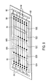
Each slave device 52A-52F includes a scan-in pad 100 and a scan out pad 102. Bond wires 76 are used to connect a scan out pad 102 to a scan in pad 100 of an adjacent device. For example, as shown in FIG. 13 , a bond wire 76 is used to connect scan out pad 102A of slave device 52A to scan in pad 100B of slave device 52B.
In the case of a flawed slave device, such as slave device 52D in this example, a bond wire 76 is used to connect the scan in pad 100D to a ground pad 108. The slave device 52D is configured such that it is disabled when its scan in pad 100D is grounded. Notwithstanding the flawed and disabled slave device 52D, the remaining slave devices can operate by connecting a bond wire between the scan out pad 102C and the input bypass bond pad 104A. A lead 106 connects the input bypass bond pad 104A to the output bypass bond pad 104B. A bond wire 76 links the output bypass bond pad 104B to the scan in pad 100E of slave device 52E. This configuration accommodates a flaw in a slave device 52D in a set of set of slave devices 52A-52F.
An interconnect channel 54 connects individual slave devices 41 within a single group 42. Thus, for example, interconnect channel 54A connects individual slave devices 41A, 41B, 41C, and 41D of group 42A.
In the prior art, scribe lanes 39 are placed around each individual device 41. In contrast, with the present invention, standard scribe lanes 39 can be placed around a group 42 of devices 41, while relatively narrow interior scribe lanes 38 can be placed between devices 41 within a group, since the interior scribe lanes 38 will not be used for cutting.
Space must be allocated on the wafer 40 for the scribe lanes 39. Observe that with the present invention the amount of space reserved for scribe lanes 39 can be reduced. This reduction in scribe lane space results in more chips per wafer, thus reducing cost and improving production capacity.
The novel structure of the invention facilitates new processes for testing, cutting, and packaging semiconductor devices. FIG. 16 illustrates a testing, cutting, and packaging process 140 utilized in accordance with an embodiment of the invention. The first step of the process 140 is to perform wafer level testing (step 150) of devices fabricated on the wafer. This step is performed in accordance with prior art techniques. The next processing step is to designate faulty dice (step 152). FIG. 17 illustrates a wafer 170 with designated faulty dice 172 identified in accordance with step 152. In accordance with prior art techniques, the wafer 170 would be cut to form individual dice at this point. In contrast, the present invention groups functional dice (step 154) at this point. The result of this process is shown in FIG. 18 , which illustrates the wafer 170 including grouped functional dice 180A, 180B, 180C, and 180D. In the present example, this process results in individual dice 182A, 182B, and 182C.
Interconnect is then applied to the grouped, functional dice (step 156). FIG. 19 illustrates interconnect 54 attached to the grouped, functional dice 180. At this point, scribe lines can be defined within scribe lanes that will be cut (step 158).
The next processing step shown in FIG. 16 is to cut the wafer (step 160). After the wafer is cut, grouped functional dice are packaged (step 162). Each packaged device is then tested (step 164). If an individual die is identified as non-functional at this point, a bypass is applied for the non-functional devices (step 166). This bypass operation is of the type described in connection with FIGS. 13-14 . Observe that the bypass operation may be used to disable faulty devices identified during wafer level testing. Alternately, wafer level testing may be avoided altogether and faulty devices may be identified and isolated once they are in a package.
There are a number of inventive features associated with the process of FIG. 16 . First, observe that the grouping of functional dice is not performed until after faulty dice are identified. This allows non-defective sub-circuits to be grouped according to locations of defective sub-circuits. Next, note that the interconnect is applied to selected devices after appropriate grouping. Further, the process of FIG. 16 flexibly defines scribe lines after the grouping of devices. The process of FIG. 16 further includes the step of exploiting a bypass feature for non-functional devices. This step is advantageously performed after the semiconductor is placed within its package.
The advantages of the invention are more fully appreciated with reference to FIGS. 20A-20C . FIG. 20A illustrates a wafer 40 with a set of semiconductor devices 41A-41F formed thereon. Scribe lanes 39 separate individual semiconductor devices 41. An interconnect substrate 72 is positioned over the wafer 40 and supports the interconnect channel 54. Bond pads or vias 58 are used to establish electrical communication between the interconnect channel 54 and individual semiconductor devices 41.
The configuration of FIG. 21 stands in sharp contrast to a prior art implementation shown in FIG. 22 . FIG. 22 illustrates a substrate 200A with a single slave device 202A embedded therein. Signals from the slave device 202A are routed to the motherboard 62 via package pins 206A-206N of the package 204A enclosing the substrate 200A. The motherboard 62 must support multiple packages 204A-204N. Each package 204 requires its own set of package pins 206A-206N for signal routing. Observe that the structure of FIG. 22 requires signals between slave devices 202 (e.g., from 202A to 202N) to be routed over the motherboard 62. In contrast, with the system of FIG. 21 , these slave-to-slave signals may be routed internally with the interconnect channel 54, thereby bypassing the motherboard 62. This allows for greater processing speeds. In addition, it can be readily appreciated that the configuration of FIG. 22 requires a large number of packages, whereas the system of FIG. 21 can utilize a single package for all of the slave devices 52A-52N formed within the substrate 50.
Those skilled in the art will appreciate that various combinations of the embodiments of FIGS. 4-13 may be used in accordance with the invention. That is, various techniques may be used to connect the interconnect structure to an external package or motherboard, and various techniques may be used to connect a package enclosing a set of slave devices to a motherboard or similar mounting structure.
In each embodiment of the invention, slave devices are combined to form a high density package. For example, the individually packaged slave devices 32A-32E of FIG. 2 can be substituted with a single package 90, in accordance with the invention.
Those skilled in the art will recognize a number of advantages associated with the invention. First, the invention produces high density systems. The high density systems reduce signal propagation time. In addition, the high density systems reduce packaging costs, since a number of devices are positioned in a single package, instead of each device having its own package. Further, the structure of the invention improves thermal performance, since a larger semiconductor substrate, which is highly thermally conductive, is available to spread heat.
The traces forming the interconnect channel can be extremely narrow. This facilitates high density routing. The invention also reduces the number of external inputs and outputs since many signals will only be routed internally between semiconductors.
The invention facilitates various design optimizations. For example, if five slave devices are each implemented as a memory with a small associated controller, in many cases a single controller can be used for a set of slave devices. This sharing of resources is efficient, and it also improves manufacturing yield since simplified slave devices are easier to fabricate.
Note that memory systems typically employ an even number of slave devices. Grouping an odd number of slave devices allows for redundancy in case one slave device is found to be defective during manufacturing and assembly.
The invention improves performance in master-slave systems, such as memory systems. The improved performance can be exploited to increase the information bandwidth of computers and computer subsystems.
The foregoing description, for purposes of explanation, used specific nomenclature to provide a thorough understanding of the invention. However, it will be apparent to one skilled in the art that the specific details are not required in order to practice the invention. In other instances, well known circuits and devices are shown in block diagram Corm in order to avoid unnecessary distraction from the underlying invention. Thus, the foregoing descriptions of specific embodiments of the present invention are presented for purposes of illustration and description. They are not intended to be exhaustive or to limit the invention to the precise forms disclosed, obviously many modifications and variations are possible in view of the above teachings. The embodiments were chosen and described in order to best explain the principles of the invention and its practical applications, that thereby enable others skilled in the art to best utilize the invention and various embodiments with various modifications as are suited to the particular use contemplated. It is intended that the scope of the invention be defined by the following claims and their equivalents.
Claims (20)
1. A semiconductor package comprising:
a plurality of semiconductor devices each including: a first bypass pad and a second bypass pad interconnected by a bypass lead, and connection pads;
the plurality of semiconductor devices including an inoperative device and a plurality of operational devices; and
an electrical connector connecting the first bypass pad of the inoperative device to a respective connection pad of a first device of the plurality of operational devices.
2. The semiconductor package of claim 1 , including an additional electrical connector connecting the second bypass pad of the inoperative device to a respective connection pad of a second device of the plurality of operational devices, wherein the first device and second device are interconnected by the first electrical connector, the bypass lead, and the second electrical connector.
3. The semiconductor package of claim 1 , further comprising an electrical connector connecting a connection pad of the inoperative device to a power supply voltage node to disable operation of the inoperative device.
4. The semiconductor package of claim 1 , wherein the plurality of semiconductor devices are disposed adjacent one another.
5. The semiconductor package of claim 1 , wherein the plurality of semiconductor devices are disposed in the same plane.
6. The semiconductor package of claim 1 , further comprising a plurality of electrical connectors coupling respective connection pads of adjacent operational devices.
7. A semiconductor package comprising:
a plurality of semiconductor devices, each comprising a bypass lead and a plurality of connection pads;
the plurality of semiconductor devices including a flawed device and a plurality of functional devices, including first and second functional devices disposed near to the flawed device;
a plurality of electrical connections that electrically connect a respective connection pad of the first functional device to a respective connection pad of the second functional device via the bypass lead of the flawed device.
8. The semiconductor package of claim 7 , further comprising an additional electrical connector connecting a connection pad of the flawed device to a power supply voltage node.
9. The semiconductor package of claim 8 , wherein connecting the first connection pad of the flawed device to the power supply voltage node disables operation of the flawed device.
10. The semiconductor package of claim 7 , wherein the flawed device is inoperative.
11. The semiconductor package of claim 7 , wherein the plurality of semiconductor devices are disposed adjacent one another.
12. The semiconductor package of claim 7 , wherein the plurality of semiconductor devices are disposed in the same plane.
13. A semiconductor package, comprising:
a plurality of semiconductor devices including an operative semiconductor device and an inoperative semiconductor device, wherein each of the plurality of semiconductor devices comprises: at least two bypass pads interconnected by a bypass lead, and a set of input/output pads; and
a plurality of electrical connections, each electrically coupling a respective one of the input/output pads on the operational semiconductor device to a respective bypass pad on the inoperative semiconductor device.
14. The semiconductor package of claim 13 , further comprising at least one electrical connector that electrically connects a respective input/output pad of the operative semiconductor device to a respective input/output pad of an additional operative semiconductor device via the bypass lead of the inoperative semiconductor device.
15. The semiconductor package of claim 13 , further comprising an electrical connector connecting a respective connection pad of the inoperative semiconductor device to a power supply voltage node so as to disable operation of the inoperative semiconductor device.
16. The semiconductor package of claim 13 , further comprising an additional electrical connector connecting a connection pad of the inoperative semiconductor device to a power supply voltage node.
17. The semiconductor package of claim 16 , wherein connecting the first connection pad of the flawed device to the power supply voltage node disables operation of the flawed device.
18. The semiconductor package of claim 13 , wherein the plurality of semiconductor devices are disposed adjacent one another.
19. The semiconductor package of claim 13 , wherein the plurality of semiconductor devices are disposed in the same plane.
20. The semiconductor package of claim 13 , wherein each of the input/output pads are connected to a buffer.
Priority Applications (1)
| Application Number | Priority Date | Filing Date | Title |
|---|---|---|---|
| US12/627,885 US8076759B2 (en) | 1999-12-23 | 2009-11-30 | Semiconductor package with a controlled impedance bus and method of forming same |
Applications Claiming Priority (6)
| Application Number | Priority Date | Filing Date | Title |
|---|---|---|---|
| US09/471,305 US6404660B1 (en) | 1999-12-23 | 1999-12-23 | Semiconductor package with a controlled impedance bus and method of forming same |
| US10/045,864 US6583035B2 (en) | 1999-12-23 | 2002-01-09 | Semiconductor package with a controlled impedance bus and method of forming same |
| US10/410,390 US6714431B2 (en) | 1999-12-23 | 2003-04-08 | Semiconductor package with a controlled impedance bus and method of forming same |
| US10/749,214 US6999332B2 (en) | 1999-12-23 | 2003-12-30 | Semiconductor package with a controlled impedance bus and method of forming same |
| US11/354,765 US7626248B2 (en) | 1999-12-23 | 2006-02-14 | Semiconductor package with a controlled impedance bus |
| US12/627,885 US8076759B2 (en) | 1999-12-23 | 2009-11-30 | Semiconductor package with a controlled impedance bus and method of forming same |
Related Parent Applications (1)
| Application Number | Title | Priority Date | Filing Date |
|---|---|---|---|
| US11/354,765 Continuation US7626248B2 (en) | 1999-12-23 | 2006-02-14 | Semiconductor package with a controlled impedance bus |
Publications (2)
| Publication Number | Publication Date |
|---|---|
| US20100072605A1 US20100072605A1 (en) | 2010-03-25 |
| US8076759B2 true US8076759B2 (en) | 2011-12-13 |
Family
ID=23871092
Family Applications (6)
| Application Number | Title | Priority Date | Filing Date |
|---|---|---|---|
| US09/471,305 Expired - Fee Related US6404660B1 (en) | 1999-12-23 | 1999-12-23 | Semiconductor package with a controlled impedance bus and method of forming same |
| US10/045,864 Expired - Fee Related US6583035B2 (en) | 1999-12-23 | 2002-01-09 | Semiconductor package with a controlled impedance bus and method of forming same |
| US10/410,390 Expired - Fee Related US6714431B2 (en) | 1999-12-23 | 2003-04-08 | Semiconductor package with a controlled impedance bus and method of forming same |
| US10/749,214 Expired - Fee Related US6999332B2 (en) | 1999-12-23 | 2003-12-30 | Semiconductor package with a controlled impedance bus and method of forming same |
| US11/354,765 Expired - Fee Related US7626248B2 (en) | 1999-12-23 | 2006-02-14 | Semiconductor package with a controlled impedance bus |
| US12/627,885 Expired - Fee Related US8076759B2 (en) | 1999-12-23 | 2009-11-30 | Semiconductor package with a controlled impedance bus and method of forming same |
Family Applications Before (5)
| Application Number | Title | Priority Date | Filing Date |
|---|---|---|---|
| US09/471,305 Expired - Fee Related US6404660B1 (en) | 1999-12-23 | 1999-12-23 | Semiconductor package with a controlled impedance bus and method of forming same |
| US10/045,864 Expired - Fee Related US6583035B2 (en) | 1999-12-23 | 2002-01-09 | Semiconductor package with a controlled impedance bus and method of forming same |
| US10/410,390 Expired - Fee Related US6714431B2 (en) | 1999-12-23 | 2003-04-08 | Semiconductor package with a controlled impedance bus and method of forming same |
| US10/749,214 Expired - Fee Related US6999332B2 (en) | 1999-12-23 | 2003-12-30 | Semiconductor package with a controlled impedance bus and method of forming same |
| US11/354,765 Expired - Fee Related US7626248B2 (en) | 1999-12-23 | 2006-02-14 | Semiconductor package with a controlled impedance bus |
Country Status (1)
| Country | Link |
|---|---|
| US (6) | US6404660B1 (en) |
Families Citing this family (29)
| Publication number | Priority date | Publication date | Assignee | Title |
|---|---|---|---|---|
| US6404660B1 (en) * | 1999-12-23 | 2002-06-11 | Rambus, Inc. | Semiconductor package with a controlled impedance bus and method of forming same |
| US6833984B1 (en) | 2000-05-03 | 2004-12-21 | Rambus, Inc. | Semiconductor module with serial bus connection to multiple dies |
| US6545875B1 (en) | 2000-05-10 | 2003-04-08 | Rambus, Inc. | Multiple channel modules and bus systems using same |
| US7610447B2 (en) * | 2001-02-28 | 2009-10-27 | Rambus Inc. | Upgradable memory system with reconfigurable interconnect |
| US6889304B2 (en) | 2001-02-28 | 2005-05-03 | Rambus Inc. | Memory device supporting a dynamically configurable core organization |
| US6724082B2 (en) | 2001-07-23 | 2004-04-20 | Intel Corporation | Systems having modules with selectable on die terminations |
| US6674649B2 (en) * | 2001-07-23 | 2004-01-06 | Intel Corporation | Systems having modules sharing on module terminations |
| US6918078B2 (en) * | 2001-07-23 | 2005-07-12 | Intel Corporation | Systems with modules sharing terminations |
| US6711027B2 (en) * | 2001-07-23 | 2004-03-23 | Intel Corporation | Modules having paths of different impedances |
| US6674648B2 (en) * | 2001-07-23 | 2004-01-06 | Intel Corporation | Termination cards and systems therefore |
| US6717823B2 (en) * | 2001-07-23 | 2004-04-06 | Intel Corporation | Systems having modules with buffer chips |
| US6771515B2 (en) * | 2001-07-23 | 2004-08-03 | Intel Corporation | Systems having modules with on die terminations |
| US6710616B1 (en) * | 2001-07-30 | 2004-03-23 | Lsi Logic Corporation | Wafer level dynamic burn-in |
| US7550842B2 (en) * | 2002-12-12 | 2009-06-23 | Formfactor, Inc. | Integrated circuit assembly |
| US7305509B2 (en) * | 2003-03-07 | 2007-12-04 | Dell Products L.P. | Method and apparatus for zero stub serial termination capacitor of resistor mounting option in an information handling system |
| US7417883B2 (en) * | 2004-12-30 | 2008-08-26 | Intel Corporation | I/O data interconnect reuse as repeater |
| JP4837971B2 (en) * | 2005-10-07 | 2011-12-14 | ルネサスエレクトロニクス株式会社 | Manufacturing method of semiconductor device |
| DE102006034599B4 (en) * | 2006-07-26 | 2010-01-21 | Infineon Technologies Ag | Method for interconnecting semiconductor chips produced from a wafer |
| EP1953289A1 (en) * | 2007-02-01 | 2008-08-06 | Groz-Beckert KG | Hook for a tufting machine |
| TWI370714B (en) * | 2008-01-09 | 2012-08-11 | Ind Tech Res Inst | Circuit structure and menufacturing method thereof |
| JP2012064891A (en) * | 2010-09-17 | 2012-03-29 | Toshiba Corp | Semiconductor device and method of manufacturing the same |
| US8499187B2 (en) | 2011-08-12 | 2013-07-30 | Micron Technology, Inc. | Methods and apparatuses for master-slave detection |
| US10231333B1 (en) | 2013-08-27 | 2019-03-12 | Flextronics Ap, Llc. | Copper interconnect for PTH components assembly |
| US9554465B1 (en) | 2013-08-27 | 2017-01-24 | Flextronics Ap, Llc | Stretchable conductor design and methods of making |
| US9674949B1 (en) | 2013-08-27 | 2017-06-06 | Flextronics Ap, Llc | Method of making stretchable interconnect using magnet wires |
| US9338915B1 (en) | 2013-12-09 | 2016-05-10 | Flextronics Ap, Llc | Method of attaching electronic module on fabrics by stitching plated through holes |
| US10892254B2 (en) * | 2018-06-07 | 2021-01-12 | Zhanming LI | Defect-tolerant layout and packaging for GaN power devices |
| CN110416096B (en) * | 2018-06-07 | 2023-04-18 | 苏州量芯微半导体有限公司 | Defect-tolerant layout and packaging of GaN power devices |
| US11444058B2 (en) * | 2020-11-06 | 2022-09-13 | Novatek Microelectronics Corp. | Package structure with separated street between chips |
Citations (54)
| Publication number | Priority date | Publication date | Assignee | Title |
|---|---|---|---|---|
| US4636982A (en) | 1984-05-04 | 1987-01-13 | Fujitsu Limited | Semiconductor memory device |
| US4766538A (en) | 1984-12-11 | 1988-08-23 | Kabushiki Kaisha Toshiba | Microprocessor having variable data width |
| US4985867A (en) | 1988-09-14 | 1991-01-15 | Kawasaki Steel Corporation | Semiconductor memory circuit |
| WO1991016680A1 (en) | 1990-04-18 | 1991-10-31 | Rambus Inc. | Integrated circuit i/o using a high preformance bus interface |
| US5222047A (en) | 1987-05-15 | 1993-06-22 | Mitsubishi Denki Kabushiki Kaisha | Method and apparatus for driving word line in block access memory |
| US5307469A (en) | 1989-05-05 | 1994-04-26 | Wang Laboratories, Inc. | Multiple mode memory module |
| US5334962A (en) | 1987-09-18 | 1994-08-02 | Q-Dot Inc. | High-speed data supply pathway systems |
| US5394528A (en) | 1991-11-05 | 1995-02-28 | Mitsubishi Denki Kabushiki Kaisha | Data processor with bus-sizing function |
| US5530814A (en) | 1991-10-30 | 1996-06-25 | I-Cube, Inc. | Bi-directional crossbar switch with control memory for selectively routing signals between pairs of signal ports |
| US5559970A (en) | 1993-05-06 | 1996-09-24 | Nec Corporation | Crossbar switch for multi-processor, multi-memory system for resolving port and bank contention through the use of aligners, routers, and serializers |
| US5614855A (en) | 1994-02-15 | 1997-03-25 | Rambus, Inc. | Delay-locked loop |
| US5630106A (en) | 1992-09-29 | 1997-05-13 | Ricoh Company, Ltd. | DRAM controller including bus-width selection and data inversion |
| US5652870A (en) | 1995-04-11 | 1997-07-29 | Mitsubishi Denki Kabushiki Kaisha | Microcomputer having multiplexable input-output port |
| US5655113A (en) | 1994-07-05 | 1997-08-05 | Monolithic System Technology, Inc. | Resynchronization circuit for a memory system and method of operating same |
| US5717871A (en) | 1995-08-17 | 1998-02-10 | I-Cube, Inc. | Crossbar switch with input/output buffers having multiplexed control inputs |
| US5717901A (en) | 1995-05-17 | 1998-02-10 | Altera Corporation | Variable depth and width memory device |
| US5764590A (en) | 1996-02-15 | 1998-06-09 | Mitsubishi Denki Kabushiki Kaisha | Synchronous semiconductor memory device which allows switching of bit configuration |
| US5787267A (en) | 1995-06-07 | 1998-07-28 | Monolithic System Technology, Inc. | Caching method and circuit for a memory system with circuit module architecture |
| US5793998A (en) | 1996-04-17 | 1998-08-11 | Digital Equipment Corporation | Method and apparatus for interconnection of multiple modules |
| US5798998A (en) | 1996-02-06 | 1998-08-25 | Pioneer Electronic Corporation | Optical disc reproducing device |
| US5801985A (en) | 1995-07-28 | 1998-09-01 | Micron Technology, Inc. | Memory system having programmable control parameters |
| US5808947A (en) | 1995-08-21 | 1998-09-15 | Sgs-Thomson Microelectronics, Inc. | Integrated circuit that supports and method for wafer-level testing |
| US5831925A (en) | 1996-12-03 | 1998-11-03 | Texas Instruments Incorporated | Memory configuration circuit and method |
| US5852725A (en) | 1996-05-10 | 1998-12-22 | Yen; Juei-Hsiang | PCI/ISA bus single board computer card/CPU card and backplane using eisa bus connectors and eisa bus slots |
| EP0887737A2 (en) | 1997-06-26 | 1998-12-30 | Hewlett-Packard Company | Reversible connectors |
| US5893927A (en) | 1996-09-13 | 1999-04-13 | International Business Machines Corporation | Memory device having programmable device width, method of programming, and method of setting device width for memory device |
| US5897193A (en) | 1991-07-18 | 1999-04-27 | Sony Corporation | Semiconductor wafer |
| US5933387A (en) | 1998-03-30 | 1999-08-03 | Richard Mann | Divided word line architecture for embedded memories using multiple metal layers |
| US5958033A (en) | 1997-08-13 | 1999-09-28 | Hewlett Packard Company | On- the-fly partitionable computer bus for enhanced operation with varying bus clock frequencies |
| US5995379A (en) | 1997-10-30 | 1999-11-30 | Nec Corporation | Stacked module and substrate therefore |
| US6034878A (en) | 1996-12-16 | 2000-03-07 | Hitachi, Ltd. | Source-clock-synchronized memory system and memory unit |
| US6038132A (en) | 1996-12-06 | 2000-03-14 | Mitsubishi Denki Kabushiki Kaisha | Memory module |
| US6047347A (en) | 1997-02-04 | 2000-04-04 | Advanced Micro Devices, Inc. | Computer system with programmable bus size |
| US6064585A (en) | 1994-10-11 | 2000-05-16 | Matsushita Electric Industrial Co. | Semiconductor device and method for fabricating the same, memory core chip and memory peripheral circuit chip |
| US6125157A (en) | 1997-02-06 | 2000-09-26 | Rambus, Inc. | Delay-locked loop circuitry for clock delay adjustment |
| US6138185A (en) | 1998-10-29 | 2000-10-24 | Mcdata Corporation | High performance crossbar switch |
| US6141273A (en) | 1998-12-31 | 2000-10-31 | Hyundai Electronics Industries Co., Ltd. | Circuit for setting width of input/output data in semiconductor memory device |
| US6144220A (en) | 1996-09-03 | 2000-11-07 | Xilinx, Inc. | FPGA Architecture using multiplexers that incorporate a logic gate |
| US6144576A (en) | 1998-08-19 | 2000-11-07 | Intel Corporation | Method and apparatus for implementing a serial memory architecture |
| US6175124B1 (en) | 1998-06-30 | 2001-01-16 | Lsi Logic Corporation | Method and apparatus for a wafer level system |
| US6188595B1 (en) | 1998-06-30 | 2001-02-13 | Micron Technology, Inc. | Memory architecture and addressing for optimized density in integrated circuit package or on circuit board |
| US6191998B1 (en) | 1997-10-16 | 2001-02-20 | Altera Corporation | Programmable logic device memory array circuit having combinable single-port memory arrays |
| US6214645B1 (en) | 1998-05-27 | 2001-04-10 | Anam Semiconductor, Inc. | Method of molding ball grid array semiconductor packages |
| US6219785B1 (en) | 1997-04-04 | 2001-04-17 | Altera Corporation | Reconfigurable computer architecture using programmable logic devices |
| US6240039B1 (en) | 1999-06-26 | 2001-05-29 | Samsung Electronics Co., Ltd. | Semiconductor memory device and driving signal generator therefor |
| US20010016369A1 (en) | 1999-09-13 | 2001-08-23 | Felix Zandman | Chip scale surface mount package for semiconductor device and process of fabricating the same |
| USRE37409E1 (en) | 1996-12-20 | 2001-10-16 | Rambus Inc. | Memory and method for sensing sub-groups of memory elements |
| US6307256B1 (en) | 1998-10-26 | 2001-10-23 | Apack Technologies Inc. | Semiconductor package with a stacked chip on a leadframe |
| US6307769B1 (en) | 1999-09-02 | 2001-10-23 | Micron Technology, Inc. | Semiconductor devices having mirrored terminal arrangements, devices including same, and methods of testing such semiconductor devices |
| US6311313B1 (en) | 1998-12-29 | 2001-10-30 | International Business Machines Corporation | X-Y grid tree clock distribution network with tunable tree and grid networks |
| US6404660B1 (en) | 1999-12-23 | 2002-06-11 | Rambus, Inc. | Semiconductor package with a controlled impedance bus and method of forming same |
| US6594818B2 (en) | 2001-03-21 | 2003-07-15 | Samsung Electronics Co., Ltd. | Memory architecture permitting selection of storage density after fabrication of active circuitry |
| US20040019756A1 (en) | 2001-02-28 | 2004-01-29 | Perego Richard E. | Memory device supporting a dynamically configurable core organization |
| US20040221106A1 (en) | 2001-02-28 | 2004-11-04 | Perego Richard E. | Upgradable memory system with reconfigurable interconnect |
-
1999
- 1999-12-23 US US09/471,305 patent/US6404660B1/en not_active Expired - Fee Related
-
2002
- 2002-01-09 US US10/045,864 patent/US6583035B2/en not_active Expired - Fee Related
-
2003
- 2003-04-08 US US10/410,390 patent/US6714431B2/en not_active Expired - Fee Related
- 2003-12-30 US US10/749,214 patent/US6999332B2/en not_active Expired - Fee Related
-
2006
- 2006-02-14 US US11/354,765 patent/US7626248B2/en not_active Expired - Fee Related
-
2009
- 2009-11-30 US US12/627,885 patent/US8076759B2/en not_active Expired - Fee Related
Patent Citations (57)
| Publication number | Priority date | Publication date | Assignee | Title |
|---|---|---|---|---|
| US4636982A (en) | 1984-05-04 | 1987-01-13 | Fujitsu Limited | Semiconductor memory device |
| US4766538A (en) | 1984-12-11 | 1988-08-23 | Kabushiki Kaisha Toshiba | Microprocessor having variable data width |
| US5222047A (en) | 1987-05-15 | 1993-06-22 | Mitsubishi Denki Kabushiki Kaisha | Method and apparatus for driving word line in block access memory |
| US5334962A (en) | 1987-09-18 | 1994-08-02 | Q-Dot Inc. | High-speed data supply pathway systems |
| US4985867A (en) | 1988-09-14 | 1991-01-15 | Kawasaki Steel Corporation | Semiconductor memory circuit |
| US5307469A (en) | 1989-05-05 | 1994-04-26 | Wang Laboratories, Inc. | Multiple mode memory module |
| WO1991016680A1 (en) | 1990-04-18 | 1991-10-31 | Rambus Inc. | Integrated circuit i/o using a high preformance bus interface |
| US5897193A (en) | 1991-07-18 | 1999-04-27 | Sony Corporation | Semiconductor wafer |
| US5530814A (en) | 1991-10-30 | 1996-06-25 | I-Cube, Inc. | Bi-directional crossbar switch with control memory for selectively routing signals between pairs of signal ports |
| US5394528A (en) | 1991-11-05 | 1995-02-28 | Mitsubishi Denki Kabushiki Kaisha | Data processor with bus-sizing function |
| US5630106A (en) | 1992-09-29 | 1997-05-13 | Ricoh Company, Ltd. | DRAM controller including bus-width selection and data inversion |
| US5559970A (en) | 1993-05-06 | 1996-09-24 | Nec Corporation | Crossbar switch for multi-processor, multi-memory system for resolving port and bank contention through the use of aligners, routers, and serializers |
| US5614855A (en) | 1994-02-15 | 1997-03-25 | Rambus, Inc. | Delay-locked loop |
| US5655113A (en) | 1994-07-05 | 1997-08-05 | Monolithic System Technology, Inc. | Resynchronization circuit for a memory system and method of operating same |
| US6064585A (en) | 1994-10-11 | 2000-05-16 | Matsushita Electric Industrial Co. | Semiconductor device and method for fabricating the same, memory core chip and memory peripheral circuit chip |
| US5652870A (en) | 1995-04-11 | 1997-07-29 | Mitsubishi Denki Kabushiki Kaisha | Microcomputer having multiplexable input-output port |
| US5717901A (en) | 1995-05-17 | 1998-02-10 | Altera Corporation | Variable depth and width memory device |
| US5787267A (en) | 1995-06-07 | 1998-07-28 | Monolithic System Technology, Inc. | Caching method and circuit for a memory system with circuit module architecture |
| US5801985A (en) | 1995-07-28 | 1998-09-01 | Micron Technology, Inc. | Memory system having programmable control parameters |
| US5717871A (en) | 1995-08-17 | 1998-02-10 | I-Cube, Inc. | Crossbar switch with input/output buffers having multiplexed control inputs |
| US5808947A (en) | 1995-08-21 | 1998-09-15 | Sgs-Thomson Microelectronics, Inc. | Integrated circuit that supports and method for wafer-level testing |
| US5798998A (en) | 1996-02-06 | 1998-08-25 | Pioneer Electronic Corporation | Optical disc reproducing device |
| US5764590A (en) | 1996-02-15 | 1998-06-09 | Mitsubishi Denki Kabushiki Kaisha | Synchronous semiconductor memory device which allows switching of bit configuration |
| US5793998A (en) | 1996-04-17 | 1998-08-11 | Digital Equipment Corporation | Method and apparatus for interconnection of multiple modules |
| US5852725A (en) | 1996-05-10 | 1998-12-22 | Yen; Juei-Hsiang | PCI/ISA bus single board computer card/CPU card and backplane using eisa bus connectors and eisa bus slots |
| US6144220A (en) | 1996-09-03 | 2000-11-07 | Xilinx, Inc. | FPGA Architecture using multiplexers that incorporate a logic gate |
| US5893927A (en) | 1996-09-13 | 1999-04-13 | International Business Machines Corporation | Memory device having programmable device width, method of programming, and method of setting device width for memory device |
| US5831925A (en) | 1996-12-03 | 1998-11-03 | Texas Instruments Incorporated | Memory configuration circuit and method |
| US6038132A (en) | 1996-12-06 | 2000-03-14 | Mitsubishi Denki Kabushiki Kaisha | Memory module |
| US6034878A (en) | 1996-12-16 | 2000-03-07 | Hitachi, Ltd. | Source-clock-synchronized memory system and memory unit |
| USRE37409E1 (en) | 1996-12-20 | 2001-10-16 | Rambus Inc. | Memory and method for sensing sub-groups of memory elements |
| US6047347A (en) | 1997-02-04 | 2000-04-04 | Advanced Micro Devices, Inc. | Computer system with programmable bus size |
| US6125157A (en) | 1997-02-06 | 2000-09-26 | Rambus, Inc. | Delay-locked loop circuitry for clock delay adjustment |
| US6219785B1 (en) | 1997-04-04 | 2001-04-17 | Altera Corporation | Reconfigurable computer architecture using programmable logic devices |
| EP0887737A2 (en) | 1997-06-26 | 1998-12-30 | Hewlett-Packard Company | Reversible connectors |
| US5958033A (en) | 1997-08-13 | 1999-09-28 | Hewlett Packard Company | On- the-fly partitionable computer bus for enhanced operation with varying bus clock frequencies |
| US6191998B1 (en) | 1997-10-16 | 2001-02-20 | Altera Corporation | Programmable logic device memory array circuit having combinable single-port memory arrays |
| US5995379A (en) | 1997-10-30 | 1999-11-30 | Nec Corporation | Stacked module and substrate therefore |
| US5933387A (en) | 1998-03-30 | 1999-08-03 | Richard Mann | Divided word line architecture for embedded memories using multiple metal layers |
| US6214645B1 (en) | 1998-05-27 | 2001-04-10 | Anam Semiconductor, Inc. | Method of molding ball grid array semiconductor packages |
| US6175124B1 (en) | 1998-06-30 | 2001-01-16 | Lsi Logic Corporation | Method and apparatus for a wafer level system |
| US6188595B1 (en) | 1998-06-30 | 2001-02-13 | Micron Technology, Inc. | Memory architecture and addressing for optimized density in integrated circuit package or on circuit board |
| US6496400B2 (en) | 1998-06-30 | 2002-12-17 | Micron Technology Inc. | Memory architecture and addressing for optimized density in integrated circuit package or on circuit board |
| US6144576A (en) | 1998-08-19 | 2000-11-07 | Intel Corporation | Method and apparatus for implementing a serial memory architecture |
| US6307256B1 (en) | 1998-10-26 | 2001-10-23 | Apack Technologies Inc. | Semiconductor package with a stacked chip on a leadframe |
| US6138185A (en) | 1998-10-29 | 2000-10-24 | Mcdata Corporation | High performance crossbar switch |
| US6311313B1 (en) | 1998-12-29 | 2001-10-30 | International Business Machines Corporation | X-Y grid tree clock distribution network with tunable tree and grid networks |
| US6141273A (en) | 1998-12-31 | 2000-10-31 | Hyundai Electronics Industries Co., Ltd. | Circuit for setting width of input/output data in semiconductor memory device |
| US6240039B1 (en) | 1999-06-26 | 2001-05-29 | Samsung Electronics Co., Ltd. | Semiconductor memory device and driving signal generator therefor |
| US6307769B1 (en) | 1999-09-02 | 2001-10-23 | Micron Technology, Inc. | Semiconductor devices having mirrored terminal arrangements, devices including same, and methods of testing such semiconductor devices |
| US20010016369A1 (en) | 1999-09-13 | 2001-08-23 | Felix Zandman | Chip scale surface mount package for semiconductor device and process of fabricating the same |
| US6404660B1 (en) | 1999-12-23 | 2002-06-11 | Rambus, Inc. | Semiconductor package with a controlled impedance bus and method of forming same |
| US7626248B2 (en) * | 1999-12-23 | 2009-12-01 | Rambus Inc. | Semiconductor package with a controlled impedance bus |
| US20040019756A1 (en) | 2001-02-28 | 2004-01-29 | Perego Richard E. | Memory device supporting a dynamically configurable core organization |
| US20040221106A1 (en) | 2001-02-28 | 2004-11-04 | Perego Richard E. | Upgradable memory system with reconfigurable interconnect |
| US6889304B2 (en) | 2001-02-28 | 2005-05-03 | Rambus Inc. | Memory device supporting a dynamically configurable core organization |
| US6594818B2 (en) | 2001-03-21 | 2003-07-15 | Samsung Electronics Co., Ltd. | Memory architecture permitting selection of storage density after fabrication of active circuitry |
Non-Patent Citations (7)
| Title |
|---|
| John, L.K., "VaWiRAM: A Variable Width Random Access Memory Module," 1995 IEEE, 9th International Conference on VLSI Design-1996. pp. 219-224. |
| Kirihata, T., et al., "A 390-mm2, 16-Bank, 1-Gb DDR SDRAM with Hybrid Bitline Architecture," IEEE Journal of Solid-State Circuits, vol. 34, No. 11, Nov. 1999, pp. 1580-1588. |
| Masumoto, R.T., "Configurable On-Chip RAM Incorporated Into High Speed Logic Array," Proceedings of the IEEE 1985 Custom Integrated Circuits Conference, May 20-23, 1985, pp. 240-243. |
| Microsoft Computer Dictionary, Copyright 1999, Fourth Edition, p. 145. |
| Minutes of Meeting No. 70, JC-42.3 Committee on RAM Memories, Mar. 9, 1994, Orlando, Florida, 72 pages (see, in particular, p. 62). |
| Rynearson, J., "VMEbus Daisy Chains," Reprinted from the VITA Journal. Originally writtten in Mar. 1997, last pg. of article updated Sep. 15, 1999, 2 pgs. |
| Satoh, K. et al., "A 209K-Transistor ECL Gate Array with RAM," IEEE Journal of Solid-State Circuits, vol. 24, No. 5, Oct. 1989, pp. 1275-1281. |
Also Published As
| Publication number | Publication date |
|---|---|
| US7626248B2 (en) | 2009-12-01 |
| US20060133124A1 (en) | 2006-06-22 |
| US20020058347A1 (en) | 2002-05-16 |
| US6583035B2 (en) | 2003-06-24 |
| US20030202373A1 (en) | 2003-10-30 |
| US6999332B2 (en) | 2006-02-14 |
| US20100072605A1 (en) | 2010-03-25 |
| US20040155318A1 (en) | 2004-08-12 |
| US6404660B1 (en) | 2002-06-11 |
| US6714431B2 (en) | 2004-03-30 |
Similar Documents
| Publication | Publication Date | Title |
|---|---|---|
| US8076759B2 (en) | Semiconductor package with a controlled impedance bus and method of forming same | |
| US5680342A (en) | Memory module package with address bus buffering | |
| US5400003A (en) | Inherently impedance matched integrated circuit module | |
| US6438014B2 (en) | High speed access compatible memory module | |
| US7772708B2 (en) | Stacking integrated circuit dies | |
| US5543640A (en) | Logical three dimensional interconnections between integrated circuit chips using a two dimensional multi-chip module | |
| US5434453A (en) | Semiconductor integrated circuit device and computer system using the same | |
| JPH0642523B2 (en) | Electronic circuit system with direct write design change capability | |
| US6011710A (en) | Capacitance reducing memory system, device and method | |
| US7161821B2 (en) | Apparatus and method for mounting microelectronic devices on a mirrored board assembly | |
| US20110317372A1 (en) | Semiconductor device | |
| US7015570B2 (en) | Electronic substrate with inboard terminal array, perimeter terminal array and exterior terminal array on a second surface and module and system including the substrate | |
| JPH0239101B2 (en) | ||
| CN116864469A (en) | Through silicon via array structure and semiconductor memory | |
| JPH04290258A (en) | Multichip module | |
| KR100360074B1 (en) | Logical three-dimensional interconnection between integrated circuit chips using two-dimensional multichip module packages | |
| US20050056945A1 (en) | Dynamic integrated circuit clusters, modules including same and methods of fabricating | |
| US11599484B2 (en) | Semiconductor device having plural signal buses for multiple purposes | |
| US20230290703A1 (en) | Copper Connected Glass Modules on a Glass Board | |
| JP2005063448A (en) | Stacked memory module and memory system | |
| CN116741710A (en) | Copper-bonded glass module on glass plate | |
| CN117134765A (en) | Circuit and chip with reconfigurable inter-chip connection structure | |
| JPH10284681A (en) | Memory module | |
| JPH10284682A (en) | Memory module | |
| US20070297146A1 (en) | Data Communications with an Integrated Circuit |
Legal Events
| Date | Code | Title | Description |
|---|---|---|---|
| REMI | Maintenance fee reminder mailed | ||
| LAPS | Lapse for failure to pay maintenance fees | ||
| STCH | Information on status: patent discontinuation |
Free format text: PATENT EXPIRED DUE TO NONPAYMENT OF MAINTENANCE FEES UNDER 37 CFR 1.362 |
|
| FP | Lapsed due to failure to pay maintenance fee |
Effective date: 20151213 |