US8079463B2 - Conveying device, rolling body and conveying body - Google Patents

Conveying device, rolling body and conveying body Download PDF

Info

Publication number
US8079463B2
US8079463B2 US13/042,586 US201113042586A US8079463B2 US 8079463 B2 US8079463 B2 US 8079463B2 US 201113042586 A US201113042586 A US 201113042586A US 8079463 B2 US8079463 B2 US 8079463B2
Authority
US
United States
Prior art keywords
roll
conveying
rolls
bodies
roll body
Prior art date
Legal status (The legal status is an assumption and is not a legal conclusion. Google has not performed a legal analysis and makes no representation as to the accuracy of the status listed.)
Expired - Fee Related
Application number
US13/042,586
Other versions
US20110155535A1 (en
Inventor
Walter Reist
Erwin Muller
Current Assignee (The listed assignees may be inaccurate. Google has not performed a legal analysis and makes no representation or warranty as to the accuracy of the list.)
WRH Walter Reist Holding AG
Original Assignee
WRH Walter Reist Holding AG
Priority date (The priority date is an assumption and is not a legal conclusion. Google has not performed a legal analysis and makes no representation as to the accuracy of the date listed.)
Filing date
Publication date
Priority claimed from PCT/CH2005/000144 external-priority patent/WO2005087627A1/en
Priority claimed from PCT/CH2006/000140 external-priority patent/WO2006094423A1/en
Application filed by WRH Walter Reist Holding AG filed Critical WRH Walter Reist Holding AG
Priority to US13/042,586 priority Critical patent/US8079463B2/en
Assigned to WRH WALTER REIST HOLDING AG reassignment WRH WALTER REIST HOLDING AG ASSIGNMENT OF ASSIGNORS INTEREST (SEE DOCUMENT FOR DETAILS). Assignors: MULLER, ERWIN, REIST, WALTER
Publication of US20110155535A1 publication Critical patent/US20110155535A1/en
Priority to US13/197,907 priority patent/US20110289757A1/en
Application granted granted Critical
Publication of US8079463B2 publication Critical patent/US8079463B2/en
Expired - Fee Related legal-status Critical Current
Anticipated expiration legal-status Critical

Links

Images

Classifications

    • BPERFORMING OPERATIONS; TRANSPORTING
    • B65CONVEYING; PACKING; STORING; HANDLING THIN OR FILAMENTARY MATERIAL
    • B65GTRANSPORT OR STORAGE DEVICES, e.g. CONVEYORS FOR LOADING OR TIPPING, SHOP CONVEYOR SYSTEMS OR PNEUMATIC TUBE CONVEYORS
    • B65G17/00Conveyors having an endless traction element, e.g. a chain, transmitting movement to a continuous or substantially-continuous load-carrying surface or to a series of individual load-carriers; Endless-chain conveyors in which the chains form the load-carrying surface
    • B65G17/06Conveyors having an endless traction element, e.g. a chain, transmitting movement to a continuous or substantially-continuous load-carrying surface or to a series of individual load-carriers; Endless-chain conveyors in which the chains form the load-carrying surface having a load-carrying surface formed by a series of interconnected, e.g. longitudinal, links, plates, or platforms
    • B65G17/08Conveyors having an endless traction element, e.g. a chain, transmitting movement to a continuous or substantially-continuous load-carrying surface or to a series of individual load-carriers; Endless-chain conveyors in which the chains form the load-carrying surface having a load-carrying surface formed by a series of interconnected, e.g. longitudinal, links, plates, or platforms the surface being formed by the traction element
    • B65G17/086Conveyors having an endless traction element, e.g. a chain, transmitting movement to a continuous or substantially-continuous load-carrying surface or to a series of individual load-carriers; Endless-chain conveyors in which the chains form the load-carrying surface having a load-carrying surface formed by a series of interconnected, e.g. longitudinal, links, plates, or platforms the surface being formed by the traction element specially adapted to follow a curved path
    • BPERFORMING OPERATIONS; TRANSPORTING
    • B65CONVEYING; PACKING; STORING; HANDLING THIN OR FILAMENTARY MATERIAL
    • B65GTRANSPORT OR STORAGE DEVICES, e.g. CONVEYORS FOR LOADING OR TIPPING, SHOP CONVEYOR SYSTEMS OR PNEUMATIC TUBE CONVEYORS
    • B65G17/00Conveyors having an endless traction element, e.g. a chain, transmitting movement to a continuous or substantially-continuous load-carrying surface or to a series of individual load-carriers; Endless-chain conveyors in which the chains form the load-carrying surface
    • B65G17/30Details; Auxiliary devices
    • B65G17/38Chains or like traction elements; Connections between traction elements and load-carriers
    • B65G17/42Attaching load carriers to traction elements
    • BPERFORMING OPERATIONS; TRANSPORTING
    • B65CONVEYING; PACKING; STORING; HANDLING THIN OR FILAMENTARY MATERIAL
    • B65GTRANSPORT OR STORAGE DEVICES, e.g. CONVEYORS FOR LOADING OR TIPPING, SHOP CONVEYOR SYSTEMS OR PNEUMATIC TUBE CONVEYORS
    • B65G35/00Mechanical conveyors not otherwise provided for
    • BPERFORMING OPERATIONS; TRANSPORTING
    • B65CONVEYING; PACKING; STORING; HANDLING THIN OR FILAMENTARY MATERIAL
    • B65GTRANSPORT OR STORAGE DEVICES, e.g. CONVEYORS FOR LOADING OR TIPPING, SHOP CONVEYOR SYSTEMS OR PNEUMATIC TUBE CONVEYORS
    • B65G39/00Rollers, e.g. drive rollers, or arrangements thereof incorporated in roller-ways or other types of mechanical conveyors 
    • B65G39/10Arrangements of rollers
    • B65G39/20Arrangements of rollers attached to moving belts or chains
    • FMECHANICAL ENGINEERING; LIGHTING; HEATING; WEAPONS; BLASTING
    • F16ENGINEERING ELEMENTS AND UNITS; GENERAL MEASURES FOR PRODUCING AND MAINTAINING EFFECTIVE FUNCTIONING OF MACHINES OR INSTALLATIONS; THERMAL INSULATION IN GENERAL
    • F16CSHAFTS; FLEXIBLE SHAFTS; ELEMENTS OR CRANKSHAFT MECHANISMS; ROTARY BODIES OTHER THAN GEARING ELEMENTS; BEARINGS
    • F16C33/00Parts of bearings; Special methods for making bearings or parts thereof
    • F16C33/30Parts of ball or roller bearings
    • F16C33/46Cages for rollers or needles
    • F16C33/50Cages for rollers or needles formed of interconnected members, e.g. chains
    • F16C33/506Cages for rollers or needles formed of interconnected members, e.g. chains formed as a flexible belt
    • FMECHANICAL ENGINEERING; LIGHTING; HEATING; WEAPONS; BLASTING
    • F16ENGINEERING ELEMENTS AND UNITS; GENERAL MEASURES FOR PRODUCING AND MAINTAINING EFFECTIVE FUNCTIONING OF MACHINES OR INSTALLATIONS; THERMAL INSULATION IN GENERAL
    • F16CSHAFTS; FLEXIBLE SHAFTS; ELEMENTS OR CRANKSHAFT MECHANISMS; ROTARY BODIES OTHER THAN GEARING ELEMENTS; BEARINGS
    • F16C29/00Bearings for parts moving only linearly
    • F16C29/04Ball or roller bearings
    • F16C29/06Ball or roller bearings in which the rolling bodies circulate partly without carrying load
    • YGENERAL TAGGING OF NEW TECHNOLOGICAL DEVELOPMENTS; GENERAL TAGGING OF CROSS-SECTIONAL TECHNOLOGIES SPANNING OVER SEVERAL SECTIONS OF THE IPC; TECHNICAL SUBJECTS COVERED BY FORMER USPC CROSS-REFERENCE ART COLLECTIONS [XRACs] AND DIGESTS
    • Y10TECHNICAL SUBJECTS COVERED BY FORMER USPC
    • Y10TTECHNICAL SUBJECTS COVERED BY FORMER US CLASSIFICATION
    • Y10T29/00Metal working
    • Y10T29/49Method of mechanical manufacture
    • Y10T29/49544Roller making
    • Y10T29/49547Assembling preformed components
    • YGENERAL TAGGING OF NEW TECHNOLOGICAL DEVELOPMENTS; GENERAL TAGGING OF CROSS-SECTIONAL TECHNOLOGIES SPANNING OVER SEVERAL SECTIONS OF THE IPC; TECHNICAL SUBJECTS COVERED BY FORMER USPC CROSS-REFERENCE ART COLLECTIONS [XRACs] AND DIGESTS
    • Y10TECHNICAL SUBJECTS COVERED BY FORMER USPC
    • Y10TTECHNICAL SUBJECTS COVERED BY FORMER US CLASSIFICATION
    • Y10T29/00Metal working
    • Y10T29/49Method of mechanical manufacture
    • Y10T29/49826Assembling or joining

Definitions

  • the invention is in the field of conveying technology and concerns a conveying device and a rolling body as well as a conveying body according to the generic terms of the corresponding independent claims.
  • the invention concerns conveying devices for transport of individual objects or bulk goods in a flowing conveying movement.
  • the object set hereby is to create conveying devices using simple and cost-efficient means.
  • a conveying device comprises several conveying bodies which roll on a guidance via several rolls, wherein the rolls are mutually connected and distances by means of a flexible connecting body.
  • the conveying bodies advantageously include means for mutual support, which prevent a movement of the conveying bodies out of the guidance.
  • the conveying bodies advantageously include means for mutual support, which prevent a movement of the conveying bodies out of the guidance.
  • less rolls per conveying body are necessary because each conveying body need not be supported by multiple rolls all the time.
  • shorter conveying bodies may be used, which again allows smaller curve radii of the guidance or the conveying device respectively.
  • a connecting body and allocated rolls form a roll body, wherein the roll body on average comprises two or less rolls per conveying body in a conveying direction.
  • two roll bodies are arranged on the left and the right respectively of a sequence of conveying bodies in the guidance, and support and guide the conveying bodies. Additionally, a third roll body may run beneath the conveying bodies and absorb a larger load in vertical direction.
  • a drive of the conveying device preferably engages on the conveying bodies, which thus move each other by pushing. Different means for transport of goods to be conveyed may be attached to the conveying bodies.
  • the means for mutual supporting are preferably flexible connections between the conveying bodies, in particular a core leading through a plurality of conveying bodies, i.e. a continuous flexible element.
  • the means for mutual support may be mutually engaging shapings on the conveying bodies.
  • these shapings allow the conveying bodies to be drawn apart to any distance in a conveying direction. This means that the conveying bodies are only loosely connected in a separable manner, that they may only push, but not draw each other respectively.
  • mutually fitting shapings of the conveying bodies form a cylindrical joint or a ball-joint.
  • the connecting body comprises: supporting regions in which the rolls are fitted and joint regions, which flexibly connect the supporting regions to each other.
  • the conveying bodies may comprise means for the intermittent support of objects to be conveyed, e.g. clamps or grippers.
  • the conveying bodies run around a central body, such that the central body may roll on a counter body.
  • the rolls and the conveying body replace a wheel for the central body.
  • the central body may comprise means for the intermittent support of objects to be conveyed.
  • a roll body for a conveying device comprises a plurality of rolls mutually connected and distanced in linear manner, wherein the rolls are connected through a flexible and in particular also elastic connecting body.
  • the connecting body thus, forms a movable bearing cage, also called cage band (cage web).
  • the cage band is bendable in at least two directions.
  • the connecting body preferably comprises holding regions, into which the rolls are fitted and joint regions, which flexibly connect the holding regions to each other.
  • the roll body may, thus, not only move on a flat orbit but also along an orbit which is set on a curved area.
  • the roll body is reversibly bendable in two directions, wherein both these directions and one movement direction of the roll body respectively are perpendicular to one another.
  • a roll body with this kind of cage band or connecting body may be produced as a standardized mass product of any length and be diversely applied in different conveying devices, roll elements and bearings of manifold kind.
  • smoothly running roll bodies may be manufactured in a very cost-effective manner.
  • the roll bodies according to the invention are particularly applicable in conveying devices as described in Swiss patent application CH 456/04 dated Mar. 18, 2004 and international application PCT/CH 2005/000144 dated Mar. 11, 2005 and basing on the priority of the first mentioned, as well as in roll elements as described in Swiss patent application CH 884/04 dated May 21, 2004 and international application PCT/CH 2005/000288 dated May 20, 2005 and relying on the priority of the former.
  • a drive of the conveying device may be implemented by a web, which is pressed against the conveying bodies and/or encloses a sequence of conveying bodies along a curve in the conveying line.
  • a drive may also be implemented with e.g. drive cams, which are guided along the conveying bodies over a certain distance and engage on several conveying bodies.
  • This kind of drive may be implemented by a driven roll element as described in Swiss patent application CH 885/04 dated May 21, 2004 and international application PCT/CH 2005/000289 dated May 20, 2005 and relying on the priority of the former.
  • the rolls or protruding cams of a revolving roll body of the driven roll element engage in the conveying device and in particular in its conveying bodies.
  • the connecting body is a one-piece body, e.g. made of plastic and the rolls are fitted directly into the connecting body or via a bearing body or a roll ring.
  • the rolls are one-piece (integrally formed) and have a barrel shape and bearing locations facing each other are provided on the respective insides of the supporting areas.
  • protruding axis elements which in particular correspond with the form of the bearing locations, are provided.
  • the rolls are fitted into the bearing locations by means of the axis elements.
  • roller shape in particular comprises the form of a circular cylinder with circular cross-section or of a barrel-shaped, embossed cylinder or a cylinder with a slightly concave barrel.
  • the rolls are advantageously made in one piece and made of metal or plastic.
  • the insides of the supporting areas may comprise projecting bearing protrusions respectively facing each other and recesses preferably corresponding with the shape of the bearing locations are provided in the rolls.
  • the rolls may be fitted into the bearing protrusions by means of the recesses.
  • protruding axis elements or the bearing protrusions respectively these preferably have a tapered shape, and in particular end in a point.
  • the rolls are ball-shaped and snapped in place in the respective bearing bodies, which are fitted into the connecting body.
  • the bearing bodies are in particular roll rings which enclose the rolls, such that the rolls may roll on two opposing sides on a different body.
  • the bearing bodies may, however, also only enclose the rolls partially from one side, such that the rolls may roll on other bodies on three sides.
  • the rolls advantageously form a single linear succession or a line of rolls inside the roll body. It is also possible to arrange two or more lines of rolls next to each other inside the same roll body.
  • FIG. 1 shows a conveying device according to the invention in a top view
  • FIG. 2 shows the same conveying device in a sectional view
  • FIGS. 3 and 4 show a further conveying device in a top view and in a sectional view
  • FIG. 5 shows a movement of conveying bodies in a curved embodiment of the further conveying device
  • FIG. 6 shows corresponding conveying bodies
  • FIG. 7 shows a conveying device with circulating conveying bodies
  • FIGS. 8 and 9 show roll bodies with ball-shaped rolls
  • FIGS. 10 to 18 show roll bodies with barrel-shaped rolls
  • FIGS. 19 to 20 show further embodiments of roll bodies
  • FIG. 1 shows a conveying device 100 according to the invention in a top view and FIG. 2 in a sectional view.
  • a conveying rail 101 several conveying bodies 102 succeeding in a longitudinal direction are guided and supported through roll bodies 2 running on both sides.
  • the conveying bodies 102 comprise a guiding groove 108 on each side, which corresponds with the shape of rolls 3 .
  • the rolling bodies 2 comprise connecting bodies 9 and rolls 3 embedded therein.
  • the conveying bodies 102 are individual blocks or lamellae, wherein in a longitudinal direction several lamellae are provided per roll 3 .
  • the blocks or lamellae are connected by means of a core 103 , i.e. a flexible cord, cable or monofilament running through the conveying bodies 102 .
  • the core 103 is loosely guided through the conveying bodies 102 or is connected to the conveying bodies, which restricts a torsion of the conveying bodies 102 around core 103 .
  • the core 103 supports conveying bodies 102 in the regions in which they are not supported by the roll body 2 itself.
  • FIGS. 3 and 4 show a further conveying device 100 in a top view and in section.
  • the conveying bodies 102 have the shape of blocks. In a longitudinal direction, approximately one conveying body 102 is provided per roll 3 .
  • the conveying bodies 102 In order for the conveying bodies 102 not to fall out of the guiding rail 101 they are provided with connecting elements 104 , 105 for mutual support.
  • FIG. 5 shows a movement of conveying bodies 102 in a curved embodiment of the further conveying device 100 .
  • FIG. 6 shows corresponding differing variants of individual conveying bodies 102 in a mutual side view 6 a and in differing top views 6 b , 6 c .
  • the joint convexities 104 and the joint concavities 105 are ball-shaped ( FIG. 6 b ) or cylindrical ( FIG. 6 c ), whereas one respective joint convexity 104 of a conveying body 102 fits into one joint concavity 105 of a subsequent conveying body 102 .
  • the conveying bodies 102 are provided with one guiding groove 108 on each respective side, which groove corresponds with the shape of rolls 3 .
  • the two roll bodies 2 of conveying device 100 or their direction of movement, respectively, thus run in a plane substantially parallel to both sides of conveying bodies 102 and their direction of movement, wherein the means 104 , 105 for mutual support prevent a relative movement of conveying bodies 102 perpendicular to this plane.
  • the direction of movement is to be understood as being tangential.
  • first bevelings 106 between the faces and an inner side 22 .
  • These bevelings begin, as can be seen in a lateral projection as in FIG. 5 or FIG. 6 a , in the location of the cylinder axis or the ball center respectively.
  • the first bevelings 106 lead from here to the inner sides 22 of conveying body 102 , such that a succession of conveying bodies 102 may curve in a direction of its inner sides 22 , wherein two respective conveying bodies 102 rotate around the intermediate joint 104 , 105 . If the conveying bodies 102 are pressed against one another, the upper parts of their faces come to lie against each other in a close fitting manner and prevent a downward buckling of the conveying bodies 102 .
  • second bevelings 107 are provided on the face, which allows a curving of a succession of conveying bodies 102 in the same plane, along which plane the conveying bodies 102 and the roll bodies 2 running laterally along the conveying bodies 2 move.
  • the second bevelings 107 in a projection from above, i.e. in a view as in FIG. 3 , 6 b or 6 c , lead from a line through the ball center to the sides left and right of the conveying body 102 . By means of contact along this line the mutual support of the conveying bodies towards the bottom is ensured.
  • Second bevelings 107 are drawn in exemplary manner in FIG. 3 in broken lines.
  • FIG. 7 shows a conveying device 100 with circulating conveying bodies 102 in a lateral view 7 a and in a cross-sectional view 7 b .
  • the conveying bodies 102 run in a conveying course 17 and are laterally supported by a roll body 2 with ball-shaped rolls 3 in bearing grooves 14 of the conveying course 17 .
  • a roll body 2 with ball-shaped rolls 3 in bearing grooves 14 of the conveying course 17 Alternatively to the roll body 2 with balls one of the roll bodies 2 with barrels presented further below may be used.
  • the quantity of conveying bodies 102 is usually larger than shown in the drawing and thus forms a conveying band or conveying chain.
  • the conveying bodies 102 may e.g. be equipped with grippers.
  • the conveying bodies 102 may transport individual or bulk goods by means of their movement.
  • the arrangement according to FIG. 7 may be designed as a roll element 10 , which can roll on a counter body 5 shown in broken lines, via the conveying bodies 102 , which hereby act as support bodies 82 .
  • a central body 1 of the roll element 10 as well as an object connected to it may thus be conveyed in relation to the counter body 5 as a whole.
  • the support bodies 82 and the roll bodies 2 thus replace a bearing of the central body 1 by means of wheels.
  • the guiding rail 101 In the transition between the straight section and the curved section s 2 with a determined curve radius the guiding rail 101 , preferably, comprises an intermediate section s 1 with a larger curve radius than the first curve radius.
  • a guiding protrusion 109 which limits the guiding groove 108 towards the inside, is curved.
  • the abutting guiding protrusions 109 at least approximately form a segment of circle in the curved region of the orbit 17 , along which segment the rolls 3 may roll in an even movement.
  • FIGS. 8 and 9 show rolling bodies 2 with ball-shaped rolls.
  • FIGS. 8 a and 8 b show the complete roll bodies 2 in a top view 8 a and a cross-sectional view 8 b .
  • FIGS. 9 a , 9 b and 9 c show a connecting body 9 or cage band, a roll ring 83 in cross-section and a ball-shaped roll 3 .
  • the connecting body 9 on the one hand comprises ring-like supporting regions 91 , into which the rolls are fitted by means of the roll rings 83 and on the other hand joint regions 92 , which flexibly connect the supporting regions 91 to each other.
  • the roll rings 83 are e.g.
  • the connecting body 9 is preferably made of elastic flat material made of plastic or rubber or a blended fabric, e.g. by means of punching or water jet cutting.
  • the connecting body 9 comprises no narrow joint regions 92 but is a band of constant width, into which the rolls 3 are fitted.
  • FIGS. 10 to 18 show roll bodies with barrel-shaped rolls.
  • FIGS. 10 a and 10 b show a roll body 2 in a top view 10 a and a cross-sectional view 10 b .
  • FIGS. 11 a and 11 b show a connecting body 9 or cage band and a barrel-shaped roll 3 .
  • the connecting body 9 on the one hand comprises ring-like supporting regions 91 , into which the rolls are fitted, and on the other hand joint regions 92 , which flexibly connect the supporting regions 91 to one another.
  • the connecting body 9 is preferably made of one piece and consists of a flexible or elastic, but not soft elastic material e.g. a plastic such as nylon. It is manufactured by means of injection molding or made of a flat material, e.g.
  • the rolls 3 are also made of plastic or of metal, in particular of steel. In this embodiment of the invention the rolls 3 are conical and tapered in an axial direction, by which conical axis elements 95 are created, as may be seen in the detailed view according to FIG. 12 .
  • On the insides of the supporting regions 91 corresponding respective opposing cavities such as e.g. internal tapers are shaped to form bearings 94 . These inner tapers effect the bearing of rolls 3 .
  • a different form may be used for the bearing, e.g. a cylindrical form.
  • the connection through the joint regions 92 is, viewed in the running direction of rolls 3 , at least approximately arranged at the middle of rolls 3 .
  • This kind of cage band 9 may be bent within a plane transverse to the roll axes and in this manner may be used together with a central body 1 e.g. according to FIG. 7 .
  • the connecting body 9 may, however, also be bent out of this plane, such that the central body 1 need not have a planar orbit. Furthermore the cage band 9 may be twisted through the joint regions 92 and, thus, the roll body 2 may follow a course, which requires a torsion of the roll body 2 .
  • This kind of roll body thus, allows a multitude of applications and can additionally be produced in a simple manner in large quantities.
  • FIGS. 13 and 14 show a further roll body 1 in a top view 13 a and a cross-sectional view 13 b .
  • FIGS. 14 a and 14 b show a corresponding connecting body 9 or cage web and a barrel-shaped roll 3 . These are producible in a similar manner to those in FIGS. 10 and 11 .
  • the rolls 3 accordingly comprise two recesses 97 for bearings, wherein these recesses 97 may also be formed by means of a continuous hole along the roll axis.
  • the supporting region 91 of the connecting body 9 comprises opposing bearing protrusions 96 , which snap into the recesses 97 when fitting the rolls.
  • the bearing protrusions 96 as well as the axis elements 95 of the previous embodiment are preferably designed to be tapered and in particular acute.
  • FIG. 15 shows a further variant with a bearing protrusion on the support region 91 in a detailed view.
  • FIG. 16 shows a variant of a roll body 2 of different proportions.
  • FIG. 17 shows a variant of a roll body 2 , in which the rolls 3 comprise protruding bearing axes 31 , which are bedded in bearing openings of connecting body 9 .
  • the connecting body 9 comprises two separate halves or bearing bands, which respectively connect the bearing axes 31 on both sides of the roll body 2 . Accordingly, the roll body 2 as a whole is only bendable in one direction. In order for the roll body 2 not to fall apart and all the same may be assembled, the bearing axes 31 e.g.
  • the bearing axes 31 may be fitted to the connecting body 9 by means of a press fit.
  • the bearing axes may, however, also be shaped to fit the rolls 3 and lie loosely in the supporting regions 91 of the connecting bodies 9 .
  • FIG. 19 shows a roll element 10 with a roll body 2 similar to the one of FIGS. 10 and 11 .
  • the roll body 2 circulates in an orbit 17 around a central body 1 and accordingly allows rolling and thus a bearing of roll element 10 with respect to connecting body 9 .
  • FIG. 20 shows a movement of a roll body 2 in a curved guiding rail 101 , e.g. in a curved roll element 10 seen from the movement direction of the roll body 2 , here accordingly the movement of the rolls 3 is curved in two directions perpendicular each other and to the direction of movement.
  • cage bands 9 Basically the different shown variants of cage bands 9 , roll shapes, roll bearings, roll elements etc. may be combined and modified in a multiplicity of manners.

Abstract

A conveying device (100) according to the invention includes several conveying bodies (102), which roll on a guidance (101) via several rolls (3), wherein the rolls (3) are connected and mutually distanced by means of a flexible connecting body (9) The conveying bodies (102) include means (103; 104, 105) for mutual support, which prevent a movement of the conveying bodies (102) out of the guidance (101). A connecting body (9) and allocated rolls (3) form a roll body (2), wherein the roll body (2), on average, includes two or less than two rolls (3) per conveying body (102). A roll body (2) for a conveying device (100) includes a plurality of rolls (3) mutually connected in a linear manner, wherein the rolls (3) are mutually connected and distanced by means of a flexible and in particular also elastic connecting body (9). In a preferred embodiment, the connecting body (9) may be bent in at least two directions.

Description

This application is a continuation of U.S. application Ser. No. 11/908,193 filed on Nov. 7, 2007 and which is currently pending.
BACKGROUND OF THE INVENTION
The invention is in the field of conveying technology and concerns a conveying device and a rolling body as well as a conveying body according to the generic terms of the corresponding independent claims.
In particular the invention concerns conveying devices for transport of individual objects or bulk goods in a flowing conveying movement. Among others, the object set hereby is to create conveying devices using simple and cost-efficient means.
This object is solved by a conveying device and a roll body as well as a conveying body according to the generic term of the independent claims.
BRIEF SUMMARY OF THE INVENTION
A conveying device according to the invention comprises several conveying bodies which roll on a guidance via several rolls, wherein the rolls are mutually connected and distances by means of a flexible connecting body.
The conveying bodies advantageously include means for mutual support, which prevent a movement of the conveying bodies out of the guidance. Thus it is possible, that less rolls per conveying body are necessary because each conveying body need not be supported by multiple rolls all the time. Conversely at a given distance between rolls shorter conveying bodies may be used, which again allows smaller curve radii of the guidance or the conveying device respectively. Thus especially a connecting body and allocated rolls form a roll body, wherein the roll body on average comprises two or less rolls per conveying body in a conveying direction.
In a preferred embodiment of the invention, two roll bodies are arranged on the left and the right respectively of a sequence of conveying bodies in the guidance, and support and guide the conveying bodies. Additionally, a third roll body may run beneath the conveying bodies and absorb a larger load in vertical direction. A drive of the conveying device preferably engages on the conveying bodies, which thus move each other by pushing. Different means for transport of goods to be conveyed may be attached to the conveying bodies.
The means for mutual supporting are preferably flexible connections between the conveying bodies, in particular a core leading through a plurality of conveying bodies, i.e. a continuous flexible element. Alternatively, the means for mutual support may be mutually engaging shapings on the conveying bodies. Advantageously, these shapings allow the conveying bodies to be drawn apart to any distance in a conveying direction. This means that the conveying bodies are only loosely connected in a separable manner, that they may only push, but not draw each other respectively.
In a preferred embodiment of the invention, mutually fitting shapings of the conveying bodies form a cylindrical joint or a ball-joint.
Between the different elements of the conveying device, i.e. guiding rail, conveying body and roll body, as well as inside the roll body, play or the possibility of movement outside the main direction of movement respectively is admissible. The play in connection allows a comparably loose connection of the elements moving against one another and all the same, a clean rolling of loaded rolls. Due to the play of the rolling body the rolls are loosely drawn and guided, such that a low friction and neither a mutual abrasion nor a canting or jamming due to low tolerances occurs.
In a different embodiment of the invention, the connecting body comprises: supporting regions in which the rolls are fitted and joint regions, which flexibly connect the supporting regions to each other.
The conveying bodies may comprise means for the intermittent support of objects to be conveyed, e.g. clamps or grippers. In a different embodiment of the invention the conveying bodies run around a central body, such that the central body may roll on a counter body. Hereby, the rolls and the conveying body replace a wheel for the central body. The central body may comprise means for the intermittent support of objects to be conveyed.
A roll body for a conveying device comprises a plurality of rolls mutually connected and distanced in linear manner, wherein the rolls are connected through a flexible and in particular also elastic connecting body. The connecting body, thus, forms a movable bearing cage, also called cage band (cage web). In a preferred embodiment of the invention, the cage band is bendable in at least two directions. For this purpose, the connecting body preferably comprises holding regions, into which the rolls are fitted and joint regions, which flexibly connect the holding regions to each other. The roll body may, thus, not only move on a flat orbit but also along an orbit which is set on a curved area. In other words: the roll body is reversibly bendable in two directions, wherein both these directions and one movement direction of the roll body respectively are perpendicular to one another.
A roll body with this kind of cage band or connecting body may be produced as a standardized mass product of any length and be diversely applied in different conveying devices, roll elements and bearings of manifold kind. By means of the use of one-piece, simply shaped, easily produced components and the allowance of play in the movements, smoothly running roll bodies may be manufactured in a very cost-effective manner.
The roll bodies according to the invention are particularly applicable in conveying devices as described in Swiss patent application CH 456/04 dated Mar. 18, 2004 and international application PCT/CH 2005/000144 dated Mar. 11, 2005 and basing on the priority of the first mentioned, as well as in roll elements as described in Swiss patent application CH 884/04 dated May 21, 2004 and international application PCT/CH 2005/000288 dated May 20, 2005 and relying on the priority of the former.
A drive of the conveying device may be implemented by a web, which is pressed against the conveying bodies and/or encloses a sequence of conveying bodies along a curve in the conveying line. A drive may also be implemented with e.g. drive cams, which are guided along the conveying bodies over a certain distance and engage on several conveying bodies. This kind of drive may be implemented by a driven roll element as described in Swiss patent application CH 885/04 dated May 21, 2004 and international application PCT/CH 2005/000289 dated May 20, 2005 and relying on the priority of the former. Hereby the rolls or protruding cams of a revolving roll body of the driven roll element engage in the conveying device and in particular in its conveying bodies.
The contents of the three cited Swiss and international applications is, thus, incorporated into the present application by reference.
In a preferred embodiment of the invention, the connecting body is a one-piece body, e.g. made of plastic and the rolls are fitted directly into the connecting body or via a bearing body or a roll ring.
In a different preferred embodiment of the invention, the rolls are one-piece (integrally formed) and have a barrel shape and bearing locations facing each other are provided on the respective insides of the supporting areas. On the rolls protruding axis elements, which in particular correspond with the form of the bearing locations, are provided. The rolls are fitted into the bearing locations by means of the axis elements. The term roller shape in particular comprises the form of a circular cylinder with circular cross-section or of a barrel-shaped, embossed cylinder or a cylinder with a slightly concave barrel. The rolls are advantageously made in one piece and made of metal or plastic.
On the other hand the insides of the supporting areas may comprise projecting bearing protrusions respectively facing each other and recesses preferably corresponding with the shape of the bearing locations are provided in the rolls. Thus, the rolls may be fitted into the bearing protrusions by means of the recesses.
In order to facilitate the fitting of the protruding axis elements or the bearing protrusions, respectively these preferably have a tapered shape, and in particular end in a point.
In a further preferred embodiment of the invention, the rolls are ball-shaped and snapped in place in the respective bearing bodies, which are fitted into the connecting body. The bearing bodies are in particular roll rings which enclose the rolls, such that the rolls may roll on two opposing sides on a different body. The bearing bodies may, however, also only enclose the rolls partially from one side, such that the rolls may roll on other bodies on three sides.
The rolls advantageously form a single linear succession or a line of rolls inside the roll body. It is also possible to arrange two or more lines of rolls next to each other inside the same roll body.
Further preferred embodiments emanate from the dependant claims.
BRIEF DESCRIPTION OF THE DRAWINGS
In the following the subject of the invention is explained in more detail by means of exemplified embodiments which are shown in the enclosed drawings. In diagrammatic manner
FIG. 1 shows a conveying device according to the invention in a top view;
FIG. 2 shows the same conveying device in a sectional view;
FIGS. 3 and 4 show a further conveying device in a top view and in a sectional view;
FIG. 5 shows a movement of conveying bodies in a curved embodiment of the further conveying device;
FIG. 6 shows corresponding conveying bodies;
FIG. 7 shows a conveying device with circulating conveying bodies;
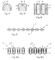
FIGS. 8 and 9 show roll bodies with ball-shaped rolls;
FIGS. 10 to 18 show roll bodies with barrel-shaped rolls; and
FIGS. 19 to 20 show further embodiments of roll bodies
DETAILED DESCRIPTION OF THE INVENTION
The reference numbers used in the drawings and their references are listed in the reference list. In the figures similar parts are in principle designated with identical reference numbers.
FIG. 1 shows a conveying device 100 according to the invention in a top view and FIG. 2 in a sectional view. In a guiding rail 101 several conveying bodies 102 succeeding in a longitudinal direction are guided and supported through roll bodies 2 running on both sides. The conveying bodies 102 comprise a guiding groove 108 on each side, which corresponds with the shape of rolls 3. The rolling bodies 2 comprise connecting bodies 9 and rolls 3 embedded therein. The conveying bodies 102 are individual blocks or lamellae, wherein in a longitudinal direction several lamellae are provided per roll 3. The blocks or lamellae are connected by means of a core 103, i.e. a flexible cord, cable or monofilament running through the conveying bodies 102. Hereby the core 103 is loosely guided through the conveying bodies 102 or is connected to the conveying bodies, which restricts a torsion of the conveying bodies 102 around core 103. In both cases, the core 103 supports conveying bodies 102 in the regions in which they are not supported by the roll body 2 itself.
FIGS. 3 and 4 show a further conveying device 100 in a top view and in section. Here the conveying bodies 102 have the shape of blocks. In a longitudinal direction, approximately one conveying body 102 is provided per roll 3. In order for the conveying bodies 102 not to fall out of the guiding rail 101 they are provided with connecting elements 104, 105 for mutual support. Here these are correspondingly shaped joint convexities 104 and joint concavities 105, as described in detail in the following figures.
FIG. 5 shows a movement of conveying bodies 102 in a curved embodiment of the further conveying device 100. FIG. 6 shows corresponding differing variants of individual conveying bodies 102 in a mutual side view 6 a and in differing top views 6 b, 6 c. The joint convexities 104 and the joint concavities 105 are ball-shaped (FIG. 6 b) or cylindrical (FIG. 6 c), whereas one respective joint convexity 104 of a conveying body 102 fits into one joint concavity 105 of a subsequent conveying body 102. The conveying bodies 102 are provided with one guiding groove 108 on each respective side, which groove corresponds with the shape of rolls 3.
The two roll bodies 2 of conveying device 100 or their direction of movement, respectively, thus run in a plane substantially parallel to both sides of conveying bodies 102 and their direction of movement, wherein the means 104, 105 for mutual support prevent a relative movement of conveying bodies 102 perpendicular to this plane. With a curved guiding rail 101, the direction of movement is to be understood as being tangential.
In order to, as in FIG. 5, enable a movement of the conveying bodies 102 out of this plane they comprise first bevelings 106 between the faces and an inner side 22. These bevelings begin, as can be seen in a lateral projection as in FIG. 5 or FIG. 6 a, in the location of the cylinder axis or the ball center respectively. The first bevelings 106 lead from here to the inner sides 22 of conveying body 102, such that a succession of conveying bodies 102 may curve in a direction of its inner sides 22, wherein two respective conveying bodies 102 rotate around the intermediate joint 104, 105. If the conveying bodies 102 are pressed against one another, the upper parts of their faces come to lie against each other in a close fitting manner and prevent a downward buckling of the conveying bodies 102.
In a further preferred embodiment of the invention second bevelings 107 are provided on the face, which allows a curving of a succession of conveying bodies 102 in the same plane, along which plane the conveying bodies 102 and the roll bodies 2 running laterally along the conveying bodies 2 move. For this purpose the second bevelings 107, in a projection from above, i.e. in a view as in FIG. 3, 6 b or 6 c, lead from a line through the ball center to the sides left and right of the conveying body 102. By means of contact along this line the mutual support of the conveying bodies towards the bottom is ensured. Second bevelings 107 are drawn in exemplary manner in FIG. 3 in broken lines.
FIG. 7 shows a conveying device 100 with circulating conveying bodies 102 in a lateral view 7 a and in a cross-sectional view 7 b. The conveying bodies 102 run in a conveying course 17 and are laterally supported by a roll body 2 with ball-shaped rolls 3 in bearing grooves 14 of the conveying course 17. Alternatively to the roll body 2 with balls one of the roll bodies 2 with barrels presented further below may be used. In a fixedly installed conveying course 17 or guiding rail the quantity of conveying bodies 102 is usually larger than shown in the drawing and thus forms a conveying band or conveying chain. For this purpose the conveying bodies 102 may e.g. be equipped with grippers. The conveying bodies 102 may transport individual or bulk goods by means of their movement.
In a different manner of application, the arrangement according to FIG. 7 may be designed as a roll element 10, which can roll on a counter body 5 shown in broken lines, via the conveying bodies 102, which hereby act as support bodies 82. A central body 1 of the roll element 10 as well as an object connected to it may thus be conveyed in relation to the counter body 5 as a whole. The support bodies 82 and the roll bodies 2 thus replace a bearing of the central body 1 by means of wheels.
In the transition between the straight section and the curved section s2 with a determined curve radius the guiding rail 101, preferably, comprises an intermediate section s1 with a larger curve radius than the first curve radius. Thus it is prevented that a conveying body 102 tilts into the curved region when it is moved into this region and that the succeeding conveying body 102 is lifted away from the central body 1.
In a further preferred embodiment of the invention a guiding protrusion 109, which limits the guiding groove 108 towards the inside, is curved. Thus the abutting guiding protrusions 109 at least approximately form a segment of circle in the curved region of the orbit 17, along which segment the rolls 3 may roll in an even movement.
FIGS. 8 and 9 show rolling bodies 2 with ball-shaped rolls. FIGS. 8 a and 8 b show the complete roll bodies 2 in a top view 8 a and a cross-sectional view 8 b. FIGS. 9 a, 9 b and 9 c show a connecting body 9 or cage band, a roll ring 83 in cross-section and a ball-shaped roll 3. The connecting body 9 on the one hand comprises ring-like supporting regions 91, into which the rolls are fitted by means of the roll rings 83 and on the other hand joint regions 92, which flexibly connect the supporting regions 91 to each other. The roll rings 83 are e.g. made of plastic and in one piece and comprise an inner area corresponding to a spherical area, such that the balls may be snapped into the rings 83. The roll rings 83 comprise a circumferential groove on their outer edges by means of which they are fitted into circular openings of supporting regions 91 of the connecting bodies 9. The connecting body 9 is preferably made of elastic flat material made of plastic or rubber or a blended fabric, e.g. by means of punching or water jet cutting.
In a preferred embodiment of the invention, the connecting body 9 comprises no narrow joint regions 92 but is a band of constant width, into which the rolls 3 are fitted.
FIGS. 10 to 18 show roll bodies with barrel-shaped rolls. FIGS. 10 a and 10 b show a roll body 2 in a top view 10 a and a cross-sectional view 10 b. FIGS. 11 a and 11 b show a connecting body 9 or cage band and a barrel-shaped roll 3. The connecting body 9 on the one hand comprises ring-like supporting regions 91, into which the rolls are fitted, and on the other hand joint regions 92, which flexibly connect the supporting regions 91 to one another. The connecting body 9 is preferably made of one piece and consists of a flexible or elastic, but not soft elastic material e.g. a plastic such as nylon. It is manufactured by means of injection molding or made of a flat material, e.g. by means of punching or jet cutting. The rolls 3 are also made of plastic or of metal, in particular of steel. In this embodiment of the invention the rolls 3 are conical and tapered in an axial direction, by which conical axis elements 95 are created, as may be seen in the detailed view according to FIG. 12. On the insides of the supporting regions 91 corresponding respective opposing cavities such as e.g. internal tapers are shaped to form bearings 94. These inner tapers effect the bearing of rolls 3. Instead of conical elements naturally a different form may be used for the bearing, e.g. a cylindrical form. The connection through the joint regions 92 is, viewed in the running direction of rolls 3, at least approximately arranged at the middle of rolls 3. This kind of cage band 9 may be bent within a plane transverse to the roll axes and in this manner may be used together with a central body 1 e.g. according to FIG. 7.
Due to the flexible and single connection by means of the joint regions 92 the connecting body 9 may, however, also be bent out of this plane, such that the central body 1 need not have a planar orbit. Furthermore the cage band 9 may be twisted through the joint regions 92 and, thus, the roll body 2 may follow a course, which requires a torsion of the roll body 2. This kind of roll body, thus, allows a multitude of applications and can additionally be produced in a simple manner in large quantities.
FIGS. 13 and 14 show a further roll body 1 in a top view 13 a and a cross-sectional view 13 b. FIGS. 14 a and 14 b show a corresponding connecting body 9 or cage web and a barrel-shaped roll 3. These are producible in a similar manner to those in FIGS. 10 and 11. For the manufacture of the roll 3 a further simplification is possible, as due to its simple form it may either be manufactured as an individual injection molded part or by cutting it off from a thick-walled tube. In this embodiment of the invention the rolls 3 accordingly comprise two recesses 97 for bearings, wherein these recesses 97 may also be formed by means of a continuous hole along the roll axis. The supporting region 91 of the connecting body 9 comprises opposing bearing protrusions 96, which snap into the recesses 97 when fitting the rolls. In order to simplify this, the bearing protrusions 96 as well as the axis elements 95 of the previous embodiment are preferably designed to be tapered and in particular acute.
FIG. 15 shows a further variant with a bearing protrusion on the support region 91 in a detailed view. FIG. 16 shows a variant of a roll body 2 of different proportions. FIG. 17 shows a variant of a roll body 2, in which the rolls 3 comprise protruding bearing axes 31, which are bedded in bearing openings of connecting body 9. In a variant with a top view according to FIG. 18 a, the connecting body 9 comprises two separate halves or bearing bands, which respectively connect the bearing axes 31 on both sides of the roll body 2. Accordingly, the roll body 2 as a whole is only bendable in one direction. In order for the roll body 2 not to fall apart and all the same may be assembled, the bearing axes 31 e.g. lie in the bearing bands by means of a press fit and the rolls 3 are loosely rotatable around the bearing axis 31. In the variant according to FIG. 18 b, as in the embodiments hitherto, a curve in two directions as well as a torsion or a contortion respectively is possible. Here again the bearing axes 31 may be fitted to the connecting body 9 by means of a press fit. The bearing axes may, however, also be shaped to fit the rolls 3 and lie loosely in the supporting regions 91 of the connecting bodies 9.
FIG. 19 shows a roll element 10 with a roll body 2 similar to the one of FIGS. 10 and 11. The roll body 2 circulates in an orbit 17 around a central body 1 and accordingly allows rolling and thus a bearing of roll element 10 with respect to connecting body 9.
FIG. 20 shows a movement of a roll body 2 in a curved guiding rail 101, e.g. in a curved roll element 10 seen from the movement direction of the roll body 2, here accordingly the movement of the rolls 3 is curved in two directions perpendicular each other and to the direction of movement.
Basically the different shown variants of cage bands 9, roll shapes, roll bearings, roll elements etc. may be combined and modified in a multiplicity of manners.
REFERENCE LIST
  • 1 central body
  • 10 roll element
  • 12 straight section
  • 14 bearing groove
  • 16 inner edge of bearing groove
  • 17 conveying course
  • 2 roll body
  • 22 inner side roll
  • 3 roll
  • 31 bearing axis
  • 5 counter body
  • 82 support body
  • 83 roll ring
  • 9 cage band
  • 91 support region
  • 92 joint region
  • 94 bearing
  • 95 axis element
  • 96 bearing protrusion
  • 97 recess, bore
  • 100 conveying device
  • 101 guiding rail
  • 102 conveying body
  • 103 core
  • 104 joint convexity
  • 105 joint concavity
  • 106 first beveling
  • 107 second beveling
  • 108 guiding groove
  • 109 guiding protrusion

Claims (10)

1. In a conveying device, between a guide and a conveying body, said conveying body received in the guide, the conveying body having a surface for conveying objects or bulk goods, a roll body comprising:
a plurality of rolls connected in linear manner,
wherein the rolls are connected to and distanced from each other along a conveying direction by means of a flexible connecting body,
wherein the connecting body is made in one piece, and
wherein the rolls are ball-shaped and individually snapped into a plurality of roll rings, which are individually fitted into a plurality of support regions of the connecting body
the roll body configured and operable to enable the conveying body to advance along the guide.
2. The roll body according to claim 1, wherein the roll rings comprise a circumferential groove on their outer edges by means of which they are fitted into circular openings of supporting regions of the connecting bodies.
3. The roll body according to claim 1, wherein the roll rings are shaped in one piece of plastic and comprise an inner spherical surface, such that the ball-shaped rolls may be snapped into the rings.
4. The roll body according to claim 1, wherein the connecting body is made of elastic flat material.
5. The roll body according to claim 4, wherein the connecting body is made of plastic or rubber or a blended fabric.
6. The roll body according to claim 1, wherein the connecting body comprises supporting regions, into which the ball-shaped rolls are fitted and joint regions, which flexibly connect the supporting regions to each other.
7. The roll body according to claim 6, wherein the joint regions are narrower than the supporting regions.
8. The roll body according to claim 7, wherein the roll body is bendable in at least two directions, wherein these two directions and a movement direction of the roll body are perpendicular to one another.
9. The roll body according to claim 2, wherein the roll rings are shaped in one piece of plastic and comprise an inner spherical surface, such that the ball-shaped rolls may be snapped into the rings.
10. The roll body according to claim 2, wherein the connecting body is made of elastic flat material.
US13/042,586 2005-03-11 2011-03-08 Conveying device, rolling body and conveying body Expired - Fee Related US8079463B2 (en)

Priority Applications (2)

Application Number Priority Date Filing Date Title
US13/042,586 US8079463B2 (en) 2005-03-11 2011-03-08 Conveying device, rolling body and conveying body
US13/197,907 US20110289757A1 (en) 2005-03-11 2011-08-04 Conveying device, rolling body and conveying body

Applications Claiming Priority (8)

Application Number Priority Date Filing Date Title
PCT/CH2005/000144 WO2005087627A1 (en) 2004-03-18 2005-03-11 Rolling conveying device
WOPCT/CH2005/000144 2005-03-11
CHPCT/CH2005/000144 2005-03-11
CH8782005 2005-05-20
CH878/05 2005-05-20
PCT/CH2006/000140 WO2006094423A1 (en) 2005-03-11 2006-03-07 Transport device, rolling body and transport body
US90819307A 2007-11-07 2007-11-07
US13/042,586 US8079463B2 (en) 2005-03-11 2011-03-08 Conveying device, rolling body and conveying body

Related Parent Applications (3)

Application Number Title Priority Date Filing Date
PCT/CH2006/000140 Continuation WO2006094423A1 (en) 2005-03-11 2006-03-07 Transport device, rolling body and transport body
US11/908,193 Continuation US7918331B2 (en) 2005-03-11 2006-03-07 Transport device, rolling body and transport body
US90819307A Continuation 2005-03-11 2007-11-07

Related Child Applications (1)

Application Number Title Priority Date Filing Date
US13/197,907 Division US20110289757A1 (en) 2005-03-11 2011-08-04 Conveying device, rolling body and conveying body

Publications (2)

Publication Number Publication Date
US20110155535A1 US20110155535A1 (en) 2011-06-30
US8079463B2 true US8079463B2 (en) 2011-12-20

Family

ID=39593329

Family Applications (3)

Application Number Title Priority Date Filing Date
US11/908,193 Expired - Fee Related US7918331B2 (en) 2005-03-11 2006-03-07 Transport device, rolling body and transport body
US13/042,586 Expired - Fee Related US8079463B2 (en) 2005-03-11 2011-03-08 Conveying device, rolling body and conveying body
US13/197,907 Abandoned US20110289757A1 (en) 2005-03-11 2011-08-04 Conveying device, rolling body and conveying body

Family Applications Before (1)

Application Number Title Priority Date Filing Date
US11/908,193 Expired - Fee Related US7918331B2 (en) 2005-03-11 2006-03-07 Transport device, rolling body and transport body

Family Applications After (1)

Application Number Title Priority Date Filing Date
US13/197,907 Abandoned US20110289757A1 (en) 2005-03-11 2011-08-04 Conveying device, rolling body and conveying body

Country Status (7)

Country Link
US (3) US7918331B2 (en)
EP (2) EP2210831A1 (en)
JP (1) JP5153611B2 (en)
AT (1) ATE539984T1 (en)
DK (2) DK2210832T3 (en)
ES (2) ES2386290T3 (en)
PL (1) PL2210832T3 (en)

Families Citing this family (11)

* Cited by examiner, † Cited by third party
Publication number Priority date Publication date Assignee Title
DE102008044430A1 (en) * 2008-08-14 2010-02-18 Krones Ag Funding for articles
US8057100B2 (en) * 2009-02-20 2011-11-15 Hiwin Technologies Corp. Roller holder for motion guide device
CH701358A1 (en) * 2009-06-25 2010-12-31 Wrh Walter Reist Holding Ag Conveyor and supporting.
JP5550037B2 (en) * 2009-08-19 2014-07-16 大同工業株式会社 Transport device
CH701687A1 (en) 2009-08-24 2011-02-28 Wrh Walter Reist Holding Ag Method for operating a support device for support of supported objects and a supporting device.
US8782556B2 (en) 2010-02-12 2014-07-15 Microsoft Corporation User-centric soft keyboard predictive technologies
KR101774895B1 (en) * 2010-04-08 2017-09-05 니타 가부시키가이샤 Paper sheet conveying roller
DE102010056059A1 (en) * 2010-12-23 2012-06-28 Schaeffler Technologies Gmbh & Co. Kg Rolling bearing cage and roller bearings
CH704274A1 (en) 2010-12-27 2012-06-29 Ferag Ag Chain link of a conveyor chain.
US9056620B2 (en) * 2012-12-06 2015-06-16 Gary D. Copus Material handling and load conveyance system
US10934095B2 (en) * 2018-02-06 2021-03-02 Habasit Ag Modular belt and traction element for a modular belt

Citations (41)

* Cited by examiner, † Cited by third party
Publication number Priority date Publication date Assignee Title
NL44407C (en) 1900-01-01
BE491893A (en) 1949-10-28 1949-11-14 Vogter & Sönner CONVEYOR FOR BREWERY AND DAIRY
US3028658A (en) 1959-08-17 1962-04-10 Federal Mogul Bower Bearings Retainer ring and roller bearing assembly and method and machine for assembling roller bearings
US3141542A (en) 1958-09-02 1964-07-21 Speedco Inc Automatic switching and storage conveyor
DE1273415B (en) 1966-02-03 1968-07-18 Rheinmetall Gmbh Conveyor device with transport slides running in an endless guide track on rolling bodies for assembly and / or processing lines
US3595377A (en) 1969-10-10 1971-07-27 Proctor & Schwartz Inc Circulating ball conveyor
US3923150A (en) 1973-04-09 1975-12-02 Ind Treuhand Ag Fa Device for conveying objects
US4018322A (en) 1976-06-11 1977-04-19 Rexnord Inc. Gimbaled conveyor balls
EP0139287A2 (en) 1983-10-27 1985-05-02 Ferag AG Endless conveyor
US4598957A (en) 1982-11-20 1986-07-08 NSK Torrington Company, Ltd. Rolling body fitted to a holder
GB2253248A (en) 1991-02-28 1992-09-02 Ford Motor Co A rolling bearing.
USRE34924E (en) 1990-09-13 1995-05-02 Unr Industries, Inc. Roller track for storage rack, roller conveyor, or similar apparatus
US5549391A (en) 1992-01-21 1996-08-27 Hydrel Ag Linear antifriction bearing and cage therefor
US5553946A (en) 1992-07-31 1996-09-10 Nippon Thompson Co., Ltd. Cage and rolling guide unit on which it is equipped
DE19637624A1 (en) 1996-09-16 1998-03-26 Bosch Gmbh Robert Conveyor for transporting workpieces
JPH10110728A (en) 1996-10-04 1998-04-28 Thk Kk Roller chain
EP0890755A2 (en) 1997-07-01 1999-01-13 Thk Co. Ltd. Rolling element string and linear guide device and rolling element screw device using the same
US5875878A (en) 1995-01-20 1999-03-02 Hk Systems, Inc. Roller shaft mounting for sound and motion control
US6148990A (en) 1998-11-02 2000-11-21 The Laitram Corporation Modular roller-top conveyor belt
EP1083347A2 (en) 1999-09-07 2001-03-14 THK Co., Ltd. Method of manufacturing rolling element string
US6203200B1 (en) 1999-07-16 2001-03-20 Hiroshi Teramachi Linear motion guide apparatus employing a roller train
US6309107B1 (en) 1999-06-24 2001-10-30 Nippon Thompson Co., Ltd. Linear motion guide unit
US6464062B1 (en) 2001-06-27 2002-10-15 Bernard J. Wendt Cooling bed roller inserts
US6494312B2 (en) 1998-11-02 2002-12-17 The Laitram Corporation Modular roller-top conveyor belt with obliquely-arranged rollers
US6516933B1 (en) 2000-11-03 2003-02-11 Valu Engineering, Inc. Bendable rolling conveyor guide
US6682218B2 (en) 2001-12-25 2004-01-27 Nippon Thompson Co., Ltd. Linear motion guide unit with separator between any two adjoining rolling elements
US6769528B2 (en) 2000-06-30 2004-08-03 Ronald L. Plesh, Sr. Rollers mountable to a cooling bed plate transfer grid
DE10331977A1 (en) 2003-07-14 2005-02-24 Siemens Ag Modular link conveyor for piece goods, and e.g. palettes, containers, etc. consists of connected hinged individual links each with a bearing for carrier rollers on either side moving on guide tracks
WO2005087627A1 (en) 2004-03-18 2005-09-22 Wrh Walter Reist Holding Ag Rolling conveying device
WO2005113391A2 (en) 2004-05-21 2005-12-01 Wrh Walter Reist Holding Ag Roller element
WO2005113392A2 (en) 2004-05-21 2005-12-01 Wrh Walter Reist Holding Ag Driven roller element and drive unit comprising such a roller element
US6997306B2 (en) 2004-01-21 2006-02-14 Laitram, L.L.C. Conveyor belt modules with embedded rollers retained in the modules and associated method
US7204358B2 (en) 2004-11-01 2007-04-17 Creform Corporation Wheeled conveyor rail
US7364038B2 (en) 2005-09-20 2008-04-29 Uni-Chains A/S Conveyor belt link incorporating one or more rollers
US7419303B2 (en) 2004-04-27 2008-09-02 Hiwin Technologies Corp. Ball connecting body for a rolling motion apparatus
US7419052B2 (en) 2005-05-23 2008-09-02 Tsubakimoto Chain Co. Conveyor chain
US7523820B1 (en) 2008-02-22 2009-04-28 Precision Motion Industries, Inc. Rolling element chain
US7527143B2 (en) 2006-11-03 2009-05-05 Habasit Ag Conveyor belt with intermodular supported rollers
US7563188B2 (en) 2005-04-22 2009-07-21 Tsubakimoto Chain Co. Conveyor chain
US7721874B2 (en) 2006-09-05 2010-05-25 Hiwin Technologies Corp. Roller chain for a linear guideway
US7798718B2 (en) 2005-09-29 2010-09-21 Nsk Ltd. Rolling element accommodating belt for linear guide apparatus and linear guide apparatus

Family Cites Families (9)

* Cited by examiner, † Cited by third party
Publication number Priority date Publication date Assignee Title
JPS6087111A (en) * 1983-10-17 1985-05-16 Imai Tekkosho:Kk Conveyer apparatus
JPS6317712A (en) * 1986-07-08 1988-01-25 Imai Tekkosho:Kk Conveying element for multi-dimensional conveying device
JPH06345232A (en) * 1993-05-31 1994-12-20 Johann A Krause Mas Fab Gmbh Device to transfer article
DE69616831T2 (en) * 1996-12-24 2003-01-23 Thk Co Ltd ENDLESS CAGE FOR A GUIDE AND MANUFACTURING METHOD THEREOF
US6364086B1 (en) * 1998-05-29 2002-04-02 Rexroth Star Gmbh Chain of rolling elements chain arrangement
US6287005B1 (en) * 1998-11-25 2001-09-11 Hiroshi Teramachi Roller guiding apparatus
EP1046879B1 (en) * 1999-04-23 2002-10-16 Roboth Vertriebsgesellschaft mbH Method for blasting of rocks
DE20101760U1 (en) * 2001-02-01 2002-06-13 Rexroth Star Gmbh A roller chain
US8057100B2 (en) * 2009-02-20 2011-11-15 Hiwin Technologies Corp. Roller holder for motion guide device

Patent Citations (44)

* Cited by examiner, † Cited by third party
Publication number Priority date Publication date Assignee Title
NL44407C (en) 1900-01-01
BE491893A (en) 1949-10-28 1949-11-14 Vogter & Sönner CONVEYOR FOR BREWERY AND DAIRY
US3141542A (en) 1958-09-02 1964-07-21 Speedco Inc Automatic switching and storage conveyor
US3028658A (en) 1959-08-17 1962-04-10 Federal Mogul Bower Bearings Retainer ring and roller bearing assembly and method and machine for assembling roller bearings
DE1273415B (en) 1966-02-03 1968-07-18 Rheinmetall Gmbh Conveyor device with transport slides running in an endless guide track on rolling bodies for assembly and / or processing lines
US3595377A (en) 1969-10-10 1971-07-27 Proctor & Schwartz Inc Circulating ball conveyor
US3923150A (en) 1973-04-09 1975-12-02 Ind Treuhand Ag Fa Device for conveying objects
US4018322A (en) 1976-06-11 1977-04-19 Rexnord Inc. Gimbaled conveyor balls
US4598957A (en) 1982-11-20 1986-07-08 NSK Torrington Company, Ltd. Rolling body fitted to a holder
EP0139287A2 (en) 1983-10-27 1985-05-02 Ferag AG Endless conveyor
USRE34924E (en) 1990-09-13 1995-05-02 Unr Industries, Inc. Roller track for storage rack, roller conveyor, or similar apparatus
GB2253248A (en) 1991-02-28 1992-09-02 Ford Motor Co A rolling bearing.
US5549391A (en) 1992-01-21 1996-08-27 Hydrel Ag Linear antifriction bearing and cage therefor
US5553946A (en) 1992-07-31 1996-09-10 Nippon Thompson Co., Ltd. Cage and rolling guide unit on which it is equipped
US5875878A (en) 1995-01-20 1999-03-02 Hk Systems, Inc. Roller shaft mounting for sound and motion control
DE19637624A1 (en) 1996-09-16 1998-03-26 Bosch Gmbh Robert Conveyor for transporting workpieces
JPH10110728A (en) 1996-10-04 1998-04-28 Thk Kk Roller chain
EP0890755A2 (en) 1997-07-01 1999-01-13 Thk Co. Ltd. Rolling element string and linear guide device and rolling element screw device using the same
US6070479A (en) 1997-07-01 2000-06-06 Thk Co., Ltd. Rolling element string and linear guide device and rolling element screw device using the same
US6148990A (en) 1998-11-02 2000-11-21 The Laitram Corporation Modular roller-top conveyor belt
US6494312B2 (en) 1998-11-02 2002-12-17 The Laitram Corporation Modular roller-top conveyor belt with obliquely-arranged rollers
US6309107B1 (en) 1999-06-24 2001-10-30 Nippon Thompson Co., Ltd. Linear motion guide unit
US6203200B1 (en) 1999-07-16 2001-03-20 Hiroshi Teramachi Linear motion guide apparatus employing a roller train
EP1083347A2 (en) 1999-09-07 2001-03-14 THK Co., Ltd. Method of manufacturing rolling element string
US6769528B2 (en) 2000-06-30 2004-08-03 Ronald L. Plesh, Sr. Rollers mountable to a cooling bed plate transfer grid
US7168546B2 (en) 2000-06-30 2007-01-30 Plesh Sr Ronald L Roller mountable to a cooling bed plate transfer grid
US6516933B1 (en) 2000-11-03 2003-02-11 Valu Engineering, Inc. Bendable rolling conveyor guide
US6464062B1 (en) 2001-06-27 2002-10-15 Bernard J. Wendt Cooling bed roller inserts
US6682218B2 (en) 2001-12-25 2004-01-27 Nippon Thompson Co., Ltd. Linear motion guide unit with separator between any two adjoining rolling elements
DE10331977A1 (en) 2003-07-14 2005-02-24 Siemens Ag Modular link conveyor for piece goods, and e.g. palettes, containers, etc. consists of connected hinged individual links each with a bearing for carrier rollers on either side moving on guide tracks
US6997306B2 (en) 2004-01-21 2006-02-14 Laitram, L.L.C. Conveyor belt modules with embedded rollers retained in the modules and associated method
US7216759B2 (en) 2004-01-21 2007-05-15 Laitram, L.L.C. Conveyor belt modules with embedded spherical rollers retained in the modules
WO2005087627A1 (en) 2004-03-18 2005-09-22 Wrh Walter Reist Holding Ag Rolling conveying device
US7419303B2 (en) 2004-04-27 2008-09-02 Hiwin Technologies Corp. Ball connecting body for a rolling motion apparatus
WO2005113391A2 (en) 2004-05-21 2005-12-01 Wrh Walter Reist Holding Ag Roller element
WO2005113392A2 (en) 2004-05-21 2005-12-01 Wrh Walter Reist Holding Ag Driven roller element and drive unit comprising such a roller element
US7204358B2 (en) 2004-11-01 2007-04-17 Creform Corporation Wheeled conveyor rail
US7563188B2 (en) 2005-04-22 2009-07-21 Tsubakimoto Chain Co. Conveyor chain
US7419052B2 (en) 2005-05-23 2008-09-02 Tsubakimoto Chain Co. Conveyor chain
US7364038B2 (en) 2005-09-20 2008-04-29 Uni-Chains A/S Conveyor belt link incorporating one or more rollers
US7798718B2 (en) 2005-09-29 2010-09-21 Nsk Ltd. Rolling element accommodating belt for linear guide apparatus and linear guide apparatus
US7721874B2 (en) 2006-09-05 2010-05-25 Hiwin Technologies Corp. Roller chain for a linear guideway
US7527143B2 (en) 2006-11-03 2009-05-05 Habasit Ag Conveyor belt with intermodular supported rollers
US7523820B1 (en) 2008-02-22 2009-04-28 Precision Motion Industries, Inc. Rolling element chain

Also Published As

Publication number Publication date
US20110155535A1 (en) 2011-06-30
EP2210831A1 (en) 2010-07-28
ES2380445T3 (en) 2012-05-11
ES2386290T3 (en) 2012-08-16
ATE539984T1 (en) 2012-01-15
PL2210832T3 (en) 2012-06-29
JP2008532879A (en) 2008-08-21
US20080164124A1 (en) 2008-07-10
EP2210832B1 (en) 2012-01-04
US7918331B2 (en) 2011-04-05
DK2210832T3 (en) 2012-04-10
US20110289757A1 (en) 2011-12-01
DK1858782T3 (en) 2012-08-20
EP2210832A1 (en) 2010-07-28
JP5153611B2 (en) 2013-02-27

Similar Documents

Publication Publication Date Title
US8079463B2 (en) Conveying device, rolling body and conveying body
CA2600729C (en) Conveying device, rolling body and conveying body
JP4994229B2 (en) Roller drive element
JP4986849B2 (en) Roller element, conveying device using roller element, bearing using roller element, and cage belt for roller element
US6364086B1 (en) Chain of rolling elements chain arrangement
EP0400200B1 (en) Linear motion bearing
EP1490278B1 (en) Conveyor chain
US7798717B2 (en) Spacer
US7465092B2 (en) Ball chain
CN101992929A (en) Support device for conveyor installation and method for operation of conveyor installation
US6419069B1 (en) Cross roller assembly and cross roller guiding apparatus using the same
US6575630B2 (en) Rolling element chain
JPS62196421A (en) Roller bearing device for linear motion
US7393139B2 (en) Linear guiding unit
US8177056B2 (en) Drive for conveyor means or conveyed objects
JP4998912B2 (en) Rolling guide device and roller coupling body
JP4142771B2 (en) Ball bearing for linear motion
JPS62110024A (en) Retainer for direct acting rolling bearing
KR100332540B1 (en) Whold direction conveyor carrier
JP3421946B2 (en) Cross roller connecting body and linear motion guide device incorporating the cross roller connecting body
GB2400150A (en) Bearing cage

Legal Events

Date Code Title Description
AS Assignment

Owner name: WRH WALTER REIST HOLDING AG, SWITZERLAND

Free format text: ASSIGNMENT OF ASSIGNORS INTEREST;ASSIGNORS:REIST, WALTER;MULLER, ERWIN;REEL/FRAME:025916/0576

Effective date: 20071015

STCF Information on status: patent grant

Free format text: PATENTED CASE

FEPP Fee payment procedure

Free format text: PAYOR NUMBER ASSIGNED (ORIGINAL EVENT CODE: ASPN); ENTITY STATUS OF PATENT OWNER: LARGE ENTITY

FPAY Fee payment

Year of fee payment: 4

FEPP Fee payment procedure

Free format text: MAINTENANCE FEE REMINDER MAILED (ORIGINAL EVENT CODE: REM.); ENTITY STATUS OF PATENT OWNER: LARGE ENTITY

LAPS Lapse for failure to pay maintenance fees

Free format text: PATENT EXPIRED FOR FAILURE TO PAY MAINTENANCE FEES (ORIGINAL EVENT CODE: EXP.); ENTITY STATUS OF PATENT OWNER: LARGE ENTITY

STCH Information on status: patent discontinuation

Free format text: PATENT EXPIRED DUE TO NONPAYMENT OF MAINTENANCE FEES UNDER 37 CFR 1.362

FP Lapsed due to failure to pay maintenance fee

Effective date: 20191220