US8084980B2 - HVAC actuator with internal heating - Google Patents
HVAC actuator with internal heating Download PDFInfo
- Publication number
- US8084980B2 US8084980B2 US12/397,404 US39740409A US8084980B2 US 8084980 B2 US8084980 B2 US 8084980B2 US 39740409 A US39740409 A US 39740409A US 8084980 B2 US8084980 B2 US 8084980B2
- Authority
- US
- United States
- Prior art keywords
- hvac
- component
- motor
- hvac component
- actuator
- Prior art date
- Legal status (The legal status is an assumption and is not a legal conclusion. Google has not performed a legal analysis and makes no representation as to the accuracy of the status listed.)
- Active, expires
Links
Images


Classifications
-
- G—PHYSICS
- G05—CONTROLLING; REGULATING
- G05B—CONTROL OR REGULATING SYSTEMS IN GENERAL; FUNCTIONAL ELEMENTS OF SUCH SYSTEMS; MONITORING OR TESTING ARRANGEMENTS FOR SUCH SYSTEMS OR ELEMENTS
- G05B19/00—Programme-control systems
- G05B19/02—Programme-control systems electric
- G05B19/18—Numerical control [NC], i.e. automatically operating machines, in particular machine tools, e.g. in a manufacturing environment, so as to execute positioning, movement or co-ordinated operations by means of programme data in numerical form
- G05B19/19—Numerical control [NC], i.e. automatically operating machines, in particular machine tools, e.g. in a manufacturing environment, so as to execute positioning, movement or co-ordinated operations by means of programme data in numerical form characterised by positioning or contouring control systems, e.g. to control position from one programmed point to another or to control movement along a programmed continuous path
-
- H—ELECTRICITY
- H02—GENERATION; CONVERSION OR DISTRIBUTION OF ELECTRIC POWER
- H02P—CONTROL OR REGULATION OF ELECTRIC MOTORS, ELECTRIC GENERATORS OR DYNAMO-ELECTRIC CONVERTERS; CONTROLLING TRANSFORMERS, REACTORS OR CHOKE COILS
- H02P29/00—Arrangements for regulating or controlling electric motors, appropriate for both AC and DC motors
- H02P29/60—Controlling or determining the temperature of the motor or of the drive
- H02P29/62—Controlling or determining the temperature of the motor or of the drive for raising the temperature of the motor
-
- F—MECHANICAL ENGINEERING; LIGHTING; HEATING; WEAPONS; BLASTING
- F24—HEATING; RANGES; VENTILATING
- F24F—AIR-CONDITIONING; AIR-HUMIDIFICATION; VENTILATION; USE OF AIR CURRENTS FOR SCREENING
- F24F13/00—Details common to, or for air-conditioning, air-humidification, ventilation or use of air currents for screening
- F24F13/08—Air-flow control members, e.g. louvres, grilles, flaps or guide plates
- F24F13/10—Air-flow control members, e.g. louvres, grilles, flaps or guide plates movable, e.g. dampers
- F24F13/14—Air-flow control members, e.g. louvres, grilles, flaps or guide plates movable, e.g. dampers built up of tilting members, e.g. louvre
- F24F13/1426—Air-flow control members, e.g. louvres, grilles, flaps or guide plates movable, e.g. dampers built up of tilting members, e.g. louvre characterised by actuating means
- F24F2013/1433—Air-flow control members, e.g. louvres, grilles, flaps or guide plates movable, e.g. dampers built up of tilting members, e.g. louvre characterised by actuating means with electric motors
-
- G—PHYSICS
- G05—CONTROLLING; REGULATING
- G05B—CONTROL OR REGULATING SYSTEMS IN GENERAL; FUNCTIONAL ELEMENTS OF SUCH SYSTEMS; MONITORING OR TESTING ARRANGEMENTS FOR SUCH SYSTEMS OR ELEMENTS
- G05B2219/00—Program-control systems
- G05B2219/20—Pc systems
- G05B2219/26—Pc applications
- G05B2219/2614—HVAC, heating, ventillation, climate control
Definitions
- the disclosure relates generally to HVAC actuators.
- HVAC actuators are used in a wide variety of applications, including but not limited to air dampers, water valves and the like.
- an HVAC actuator has a motor that drives a drive train.
- the drive train often functions as a sort of transmission, turning a low torque, high speed motor output into a high torque, low speed drive train output that is sufficient to open an air damper, a water valve, or the like.
- the motor may be configured to drive the drive train in a first direction to, for example, open an HVAC component and may drive the drive train in a second direction to, for example, close the HVAC component.
- Such actuators may be rotary, linear or move in some other fashion, depending on the application.
- an HVAC actuator such as a spring return actuator may have one or more return springs or other bias mechanism that opposes a driving direction of the motor.
- a spring return actuator may be configured such that the motor drives an HVAC component (e.g. damper) from a closed position to an open position, while a return spring drives the HVAC component from the open position to the closed position.
- a spring return actuator may be configured such that the motor drives an HVAC component from an open position to a closed position, while the return spring or other bias mechanism drives the HVAC component from the closed position to the open position.
- HVAC actuators may be used in a variety of environments, and thus may potentially be exposed to large temperature swings. It will be appreciated that in cool environments, frictional forces within the HVAC actuator may increase relative to frictional forces experienced in warmer environments. In some cases, lubricants become more viscous (thicker) at lower temperatures and/or tolerances such as in the bearings may become tighter. As a result, the motor within the HVAC actuator may need additional power to overcome these temperature-related effects. Also, in a spring return actuator, the return spring (or springs) may need to be able to overcome the increased motor resistance. These factors can combine to often increase the package size, product cost and power consumption of an HVAC actuator.
- a particular HVAC actuator has, at room temperature, a power consumption rating of about 5.5 VA. In a cold environment, the same HVAC actuator may have a power consumption of about 6.5 VA because of increased resistances within the HVAC actuator due to the cold temperatures. It will be appreciated that this represents an increase in power consumption of about 18 percent.
- a particular spring return actuator has, at room temperature, a back drive motor resistance of 0.1 N ⁇ m (Newton ⁇ meters) requiring a load of 2 N ⁇ m further up the drive train in order to close the device. In a cold environment, the back drive motor resistance may increase to 0.25 N ⁇ m, requiring a load of 5 N ⁇ m in order to close the device. It can be seen that this would require a stronger or more robust HVAC actuator design, which may include a stronger drive motor, stronger gearing, stronger housing and the like. This can add significant cost.
- the disclosure relates generally to HVAC actuators for driving HVAC components.
- An illustrative but non-limiting example of the disclosure may be found in an HVAC actuator that includes a drive train that is configured to drive an HVAC component along a range of motion from a first HVAC component position to a second HVAC component position via a motor that is coupled to the drive train for driving the drive train and thus the HVAC component.
- the HVAC actuator may include a controller for controlling the motor to move the HVAC component from the first HVAC component position to the second HVAC component position.
- the controller may be configured to detect a selected condition, such as a low temperature condition, and in response may apply a supplemental current component to the motor that warms the HVAC actuator without substantially moving the HVAC component.
- the spring return HVAC actuator may include a motor, a drive train that is driven by the motor and a return spring. While a return spring is used here as an example, it is contemplated that any suitable bias mechanism may be used.
- the drive train may be configured to drive the HVAC component in a first direction toward a first HVAC component position along a range of motion.
- the return spring may be configured to drive the HVAC component in a second, opposing direction.
- the spring return HVAC actuator may include a controller that is configured to operate the motor in order to drive the HVAC component in the first direction.
- a thermal monitor may be provided for detecting a temperature of the HVAC actuator and provide the controller with a signal representing the HVAC actuator temperature.
- the controller may also be configured to apply a supplemental current component to the motor or other component (e.g. resistors, heating elements, etc.) of the HVAC actuator to warm the HVAC actuator without substantially moving the HVAC component.
- an HVAC actuator for driving an HVAC component that includes a motor and a drive train driven by the motor.
- the drive train may be configured to drive the HVAC component along a range of motion.
- a controller may be configured to operate the motor in order to drive the HVAC component in a first direction to open the HVAC component and in a second direction to close the HVAC component.
- the HVAC actuator may include a thermal monitor that detects a temperature of the HVAC actuator and provides the controller with a signal representing the HVAC actuator temperature.
- the controller may be configured to actuate the motor without significantly driving the HVAC component if the HVAC actuator temperature is low in order to warm the HVAC actuator.
- FIG. 1 is a schematic view of an illustrative but non-limiting HVAC actuator
- FIG. 2 is a schematic view of an illustrative HVAC component that may be actuated via the HVAC actuator of FIG. 1 ;
- FIGS. 3 through 6 are flow diagrams showing illustrative but non-limiting examples of methods that may be carried out using the HVAC actuator of FIG. 1 ;
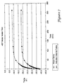
- FIG. 7 is a graphical representation of experimental data.
- HVAC component actuators may be a spring return actuator
- the HVAC component actuator may include some other biasing mechanism, or may not include a return spring or other biasing structure or mechanism at all.
- the HVAC component actuator may use a motor to drive an HVAC component in both directions, rather than using a motor to drive in a first direction and a return spring or other biasing structure to drive the HVAC component in a second direction.
- a spring return HVAC actuator may utilize the motor as a brake to limit travel speed when the return spring or other biasing structure is driving the HVAC component in the second direction.
- an HVAC component actuator may include an on-board power supply such as a battery or capacitor that can be used as a fail-safe in powering the motor long enough to drive an HVAC component to a desired position in the case of a power failure, but this is not required in all embodiments.
- an on-board power supply such as a battery or capacitor that can be used as a fail-safe in powering the motor long enough to drive an HVAC component to a desired position in the case of a power failure, but this is not required in all embodiments.
- FIG. 1 shows an illustrative but non-limiting example of an HVAC actuator 10 .
- HVAC actuator 10 is a spring return actuator but it will be appreciated that HVAC actuator 10 is not to be considered as being limited to a spring return actuator.
- HVAC actuator 10 includes a motor 12 .
- motor 12 may be a DC motor, an AC motor, a stepper motor, or any other suitable type of motor, as desired.
- motor 12 is a brushless DC motor, but this is not required.
- the torque output of motor 12 may be adjustable by, for example, altering the current (and/or voltage) that is applied to motor 12 .
- the maximum output torque of the motor 12 may be set by limiting or clipping the current (and/or voltage) that is applied to motor 12 .
- motor 12 may engage with a drive train 14 .
- drive train 14 may function as a kind of transmission, taking a relatively high speed, low torque output from motor 12 and turning it into a relatively low speed, high torque output that is suitable for driving an HVAC component 16 between two or more positions.
- HVAC component 16 may be, for example, an air damper, a fluid valve such as a ball valve, or the like.
- the particular gearing present within drive train 14 may be customized to provide an appropriate balance of speed and torque, depending on the physical characteristics and/or requirements of the corresponding HVAC component 16 .
- the drive train 14 may be configured to have an appropriate speed reduction and thus provide an appropriate level of torque.
- drive train 14 may provide a speed reduction of about 1000:1, about 2000:1, about 3000:1 or any other suitable speed reduction as desired.
- the HVAC actuator 10 may be a rotary, linear or any other suitable HVAC actuator, depending on the application.
- HVAC actuator 10 may include a bias mechanism 18 such as a return spring.
- a bias mechanism 18 such as a return spring.
- motor 12 may instead be used to drive HVAC component 16 in a first direction to, for example, open HVAC component 16 and to drive HVAC component 16 in a second direction to, for example, close HVAC component 16 . If motor 12 is used in this manner, bias mechanism 18 may be made smaller, or may even be absent.
- bias mechanism 18 may instead be disposed between drive train 14 and HVAC component 16 , between HVAC component 16 and a fixed bracket or duct, or at any other suitable location.
- Bias mechanism 18 may be any suitable structure that can provide a bias force that opposes at least one driving direction of motor 12 .
- bias mechanism 18 may be a resilient material such as a rubber, a gas cylinder, a hydraulic component, or the like.
- bias mechanism 18 may be one or more return springs. If, for example, motor 12 drives HVAC component 16 in a first direction, bias mechanism 18 may drive HVAC component 16 in an opposing direction. In some cases, motor 12 may provide a braking effect while bias mechanism 18 drives HVAC component 16 in the opposing direction.
- HVAC actuator 10 may include a controller 20 .
- Controller 20 may, for example, monitor and/or adjust the speed and/or torque of motor 12 .
- HVAC actuator 10 may include one or more sensors that are in communication with controller 20 to provide controller 20 with information pertaining to the speed of motor 12 and/or the relative position of motor 12 , drive train 14 and/or HVAC component 16 . It will be appreciated that in some instances, one or more of controller 20 and any sensors may be disposed on or in electrical communication with a printed circuit board (not illustrated) disposed within or proximate to HVAC actuator 10 .
- HVAC actuator 10 may include a first position sensor 22 that is disposed proximate to motor 12 and that is in communication with controller 20 , as well as a second position sensor 24 that is disposed proximate to drive train 14 and that is in communication with controller 20 .
- HVAC actuator 10 may include both first position sensor 22 and second position sensor 24 .
- one or both of the position sensors may be omitted or perhaps replaced with any other desired type of position or speed sensor, as desired.
- an optical encoder, potentiometer, hall effect sensor or any other suitable position sensor may be used, as desired.
- first position sensor 22 may be a sensor that outputs a signal related to motor rotation.
- first position sensor 22 may be a Hall sensor that outputs an incremental signal that represents motor rotations, although other types of sensors may be used.
- Second position sensor 24 may be a position potentiometer sensor, but this is not required. In some instances, such as if first position sensor 22 is a Hall sensor, there may be a known relationship between Hall counts and motor rotation that can be used to ascertain how many rotations motor 12 has undergone, and thus determine a position of drive train 14 . Controller 20 may rely upon both sensors, or may, in some cases, operate in accordance with a signal from first position sensor 22 as long as it is in relative agreement with a signal from second position sensor 24 . In some cases, neither position sensors 22 or 24 may be used.
- drive train 14 may have an output shaft or gear that drives the HVAC component 16 .
- the output shaft or gear may be considered as rotating through a range of motion.
- the range of motion may be defined not in terms of the rotation of the output shaft, but rather in terms of the rotation or other movement of HVAC component 16 in response to the rotating output shaft or gear.
- the range of motion may be defined as the path traveled (either via the output shaft or HVAC component 16 ) between end points.
- an illustrative HVAC component 16 is schematically shown as having a shaft 28 that may, for example, be driven by drive train 14 ( FIG. 1 ) and may be connected to whatever portion of HVAC component 16 that is to be opened or closed. If HVAC component 16 is an air damper, shaft 28 may be connected to the damper itself. If HVAC component 16 is a fluid valve such as a ball valve, shaft 28 may engage the ball valve ball itself.
- the illustrative HVAC component 16 is seen as including a first end point 30 and a second end point 32 , with a range of motion 34 defined therebetween. In some cases, first end point 30 and/or second end point 32 may represent mechanical limits of drive train 14 ( FIG. 1 ) or the HVAC component 16 . In some instances, first end point 30 and/or second end point 32 may be adjustable end points that may, for example, be set by an installer to prevent damage or set other limits to particular aspects or portions of HVAC component 16 .
- HVAC actuator 10 may include a thermal monitor 26 , but this is not required.
- Thermal monitor 26 may provide a signal to controller 20 that is at least representative of a temperature of HVAC actuator 10 .
- Thermal monitor 26 may be located in any particular position within (or near) HVAC actuator 10 , as long as thermal monitor 26 is able to detect a temperature within or around HVAC actuator 10 .
- thermal monitor 26 may be disposed next to, inside, or near motor 12 .
- thermal monitor 26 may be positioned next to or near drive train 14 .
- thermal monitor 26 may be disposed on the aforementioned printed circuit board.
- multiple thermal monitors 26 may be provided at different locations within the HVAC actuator 10 , if desired.
- Thermal monitor 26 may include or be any structure or device capable of detecting a temperature and providing a signal to controller 20 that represents the detected temperature.
- thermal monitor 26 may be an electronic thermometer.
- thermal monitor 26 may be a thermistor having a known resistance versus temperature curve.
- the thermistor may be mounted on the aforementioned printed circuit board and controller 20 may monitor a voltage provided by the thermistor, which in turn may be evaluated by controller 20 as being representative of a detected temperature.
- controller 20 may be programmed or otherwise be configured to operate motor 12 in such a way as to use motor 12 to at least partially heat the motor and/or other components of the HVAC actuator 10 , particularly if HVAC actuator 10 is used within a cold environment.
- HVAC actuator 10 may include a resistive element (not illustrated) that could be used to warm HVAC actuator 10 if a low temperature is detected.
- the resistive element may be the coils of the motor 12 , or some other resistor within the HVAC actuator.
- HVAC actuator 10 may be warmed by inefficiently operating the motor or other elements in the HVAC actuator, if desired.
- HVAC actuator 10 may not include thermal monitor 26 . If controller 20 does not have an indication of HVAC actuator temperature, or perhaps if thermal monitor 26 malfunctions, controller 20 may assume a low temperature and may maintain a motor heating routine at all times. In some cases, it is contemplated that controller 20 may ascertain a measure of the environmental temperature and/or a temperature of the HVAC actuator itself by monitoring the current draw of motor 12 . If HVAC actuator 10 is too cold, motor 12 may tend to draw relatively more current to move a particular distance (indicated for example by motor hall counts) than if motor 12 is in a warmer environment. In this instance, controller 20 may use motor current draw as an indicator of temperature.
- a thermal monitor 26 may provide controller 20 with an indication that HVAC actuator 10 is at a temperature that is considered too low for efficient operation (e.g. below a threshold temperature)
- controller 20 may operate motor 12 in a manner that will help to warm all or part of HVAC actuator 10 .
- HVAC actuator 10 is in an environment that allows HVAC actuator 10 to reach a temperature of ⁇ 40° F.
- controller 20 may operate motor 12 or some other component of HVAC actuator to warm HVAC actuator 10 to a temperature of ⁇ 15° F. It will be appreciated that these numbers are to be considered as merely illustrative.
- controller 20 may operate a motor heating routine in a binary, ON/OFF manner, i.e., if the temperature is below a predetermined level, the motor heating routine is initiated, and if the temperature is above the same or different predetermined level, the motor heating routine may be stopped. In some instances, however, controller 20 may operate a motor heating routine in a analog manner. That is, in some instances, it is contemplated that the level of heating achieved via a motor heating routine may be at least partially a function of the motor and/or actuator temperature. The function may be linear, non-linear, step or any other suitable function, as desired.
- controller 20 may use the motor 12 to warm HVAC actuator 10 .
- controller 20 may operate motor 12 in a less than optimal manner (e.g. less electrically efficient manner) while driving HVAC component 16 .
- motor 12 may create additional thermal energy that will heat HVAC actuator 10 .
- controller 12 may use motor 12 to warm HVAC actuator 10 only when HVAC actuator 10 is in a holding mode.
- a holding mode may be entered or defined as anytime that HVAC actuator 10 is not actively moving HVAC component 16 . This would include periods of time in which no or essentially no current would normally be provided to motor 12 , i.e., HVAC actuator 10 is in a rest position. In some cases, a current may be provided to motor 12 in order to counteract an opposing force provided by bias mechanism 18 (if provided) and thus hold HVAC component 16 in a stationary position.
- a holding mode may also include periods of time in which HVAC actuator 10 is holding HVAC component 16 in a position that is offset from a rest position, and possibly against the force of a biasing mechanism. These conditions may, for example, be known or detected by controller 20 .
- a holding mode may be known or detected by controller 20 by knowing or determining the relative position of drive train 14 .
- controller 20 may be programmed or otherwise provided with a known relationship between motor hall count and the rotational position of an output of drive train 14 (and hence the position of HVAC component 16 ).
- a motor hall count of about 56,500 may correspond to an output (of drive train 14 ) position of about 95 degrees.
- the motor hall count may be used by controller 20 to determine if HVAC actuator 10 is in a position that corresponds to a particular holding mode position.
- controller 20 may recognize other positions for HVAC component 16 as also qualifying as being a rest or holding position.
- controller 20 may operate motor 12 in one or more of several different manners to warm HVAC actuator 10 .
- controller 20 may provide a supplemental current component to motor 12 that is small enough to not substantially move HVAC component 16 , but still generate heat within motor 12 .
- a supplemental current component may, for example, be considered as being an amount of current being applied above and beyond any current already being applied to motor 12 to hold HVAC component 16 in a particular position. If HVAC component 16 is in a rest position in which no current is otherwise provided to motor 12 , the supplemental current component may be the only current applied to motor 12 .
- controller 20 may control the motor 12 by locking onto a single phase so that the motor does not move, and then provide a supplemental current to the motor to heat the HVAC actuator. Also, and rather than providing a supplemental current component to the motor 12 itself, or in addition to providing a supplemental current component to the motor 12 , it is contemplated that the controller 20 may provide a supplemental current component to other components (e.g. resistors, heating elements, etc.) of an HVAC actuator to warm the HVAC actuator, as desired.
- other components e.g. resistors, heating elements, etc.
- controller 20 may be programmed or otherwise configured to provide the supplemental current component to motor 12 only when HVAC component is not being driven open, driven closed and/or driven in either direction, but this is not required.
- drive train 14 may permit small motor movement without transferring significant movement to HVAC component 16 .
- motor 12 may be moved slightly without transferring significant movement to HVAC component 16 .
- HVAC component 16 whether an air damper or a ball valve, may move slightly without noticeably affecting the environment being heated, cooled or ventilated by HVAC component 16 .
- HVAC component 16 is an air damper
- the air damper may move slightly in a closing direction or an opening direction, or may oscillate between the two, without significantly affecting the air temperature within a conditioned space.
- HVAC component 16 may be considered as having a range of motion 34 .
- the supplemental current component may, for example, cause HVAC component 16 to move a distance that corresponds to less than ten percent of the range of motion 34 .
- the supplemental current component may cause HVAC component 16 to move a distance that corresponds to less than five percent of the range of motion 34 , less than three percent of the range of motion 34 , or less than one percent of the range of motion 34 .
- a similar analysis may be provided for range of motion of a linear actuator.
- the supplemental current component may cause motor 12 to oscillate about a particular position, alternately moving a small amount in a first direction followed by moving a small amount in a second direction.
- the first direction may correspond to an opening direction while the second direction may correspond to a closing direction, but this is not required. This movement may warm motor 12 without significantly or excessively moving HVAC component 16 .
- HVAC actuator 10 may include a bias mechanism 18 such as a return spring.
- controller 20 may be configured to provide a first level of current to motor 12 that is required to hold HVAC component 16 at a selected position against the bias force provided by the return spring.
- the supplemental current component if provided by controller 20 , may be above and beyond the first level of current.
- controller 20 may warm HVAC actuator 10 by providing a supplemental current component that includes a plurality of current pulses to the motor. With each current pulse, motor 12 may drive HVAC component 16 a short distance against the return spring and then allow HVAC component 16 to move a short opposite distance, driven by the return spring.
- FIG. 3 is a flow diagram showing an illustrative but non-limiting example that may be carried out via HVAC actuator 10 ( FIG. 1 ).
- control begins at decision block 36 , where controller 20 ( FIG. 1 ) determines if motor 12 ( FIG. 1 ) is in a holding or rest position. This determination may, for example, be made as discussed above with respect to current draw and/or motor hall counts. In some cases, the controller 20 may itself know if the HVAC actuator 10 is expected to be in a holding position by, for example, knowing past commands that were issued to the motor 12 .
- controller 20 may itself know that the HVAC actuator 10 should be in a holding position and therefore controller 20 will recognize that motor 12 is not actively moving HVAC component 16 . As a result, controller 20 may determine that motor 12 is in a stationary position, and may undergo a motor heating routine as discussed below.
- controller 20 determines if HVAC actuator 10 is at a temperature that is below a selected temperature. If so, control passes to block 40 where controller 20 implements a motor heating routine such as one or more of those discussed above. Otherwise, control passes to block 42 , where the motor heating routine is stopped.
- control passes to block 42 , where the motor heating routine if initiated is stopped. It is important to note that while these method steps are described in a particular order, they do not necessarily follow in chronological order.
- FIG. 4 is a flow diagram showing an illustrative but non-limiting example that may be carried out via HVAC actuator 10 ( FIG. 1 ).
- control begins at decision block 36 , where controller 20 ( FIG. 1 ) determines if motor 12 ( FIG. 1 ) is in a holding or rest position. If motor 12 is in a holding or rest position, control passes to decision block 38 .
- controller 20 determines if HVAC actuator 10 is at a temperature that is below a selected temperature. If so, control passes to block 44 where controller 20 provides a supplemental amount of current to motor 12 in order to warm motor 12 without moving or at least without substantially moving motor 12 . Otherwise, control passes to block 42 , where the motor heating routine is stopped.
- control also passes to block 42 , where the motor heating routine if initiated is stopped. It is important to note that while these method steps are described in a particular order, they do not necessarily follow in chronological order.
- FIG. 5 is a flow diagram showing an illustrative but non-limiting example that may be carried out via HVAC actuator 10 ( FIG. 1 ).
- control begins at decision block 36 , where controller 20 ( FIG. 1 ) determines if motor 12 ( FIG. 1 ) is in a holding or rest position. If motor 12 is in a holding or rest position, control passes to decision block 38 .
- controller 20 determines if HVAC actuator 10 is at a temperature that is below a selected temperature. If so, control passes to block 46 where controller 20 provides a plurality of current pulses to motor 12 so that motor 12 will oscillate, thereby generating heat to warm HVAC actuator 10 .
- each current pulse may drive motor 12 a short direction against the return spring, followed by motor 12 being driven a short opposite direction by the return spring.
- controller 20 determines the HVAC actuator 10 is not at a temperature that is below a selected temperature, control passes to block 42 , where the motor heating routine is stopped.
- control also passes to block 42 , where the motor heating routine if initiated is stopped. It is important to note that while these method steps are described in a particular order, they do not necessarily follow in chronological order.
- FIG. 6 is a flow diagram showing an illustrative but non-limiting example that may be carried out via HVAC actuator 10 ( FIG. 1 ).
- Control begins at block 48 , where controller 20 ( FIG. 1 ) determines if motor 12 ( FIG. 1 ) is in a holding or rest position. If so, control passes to decision block 50 . Otherwise, control passes to block 56 , where controller 20 halts the motor heating routine if initiated.
- controller 20 determines if HVAC actuator 10 is below a predetermined temperature. If so, control passes to decision block 52 . Otherwise, control reverts to block 56 .
- controller 20 determines if motor 12 is drawing a current draw that is below a particular level Y. If not, which indicates that motor 12 may be moving, control reverts to block 56 . If the current draw is below Y, control passes to block 54 , where controller 20 activates a motor heating routine, and in some cases, sets the motor current equal to Y or some other current level, as desired, to produce additional heat in the HVAC actuator 10 . It is important to note that while these method steps are described in a particular order, they do not necessarily follow in chronological order.
- HVAC actuator 10 was tested to demonstrate the effectiveness of internal motor heating.
- Motor 12 was a brushless DC motor controlled via Pulse Width Modulation (PWM) and a multiphase DC commutation routine.
- PWM Pulse Width Modulation
- controller 20 when controller 20 is instructed to provide heating, motor commutation stops, locking motor 12 on a single phase.
- the current being applied to the motor 12 is then given by the following equation:
- I xV R , where x is the PMW duty cycle, V is the PWM voltage, R is the resistance of the motor coils and I is the current running through the motor coils.
- x was set equal to 0.2 (20 percent duty cycle)
- V was set equal to 30 volts
- R was determined to be 13.9 ohms.
- the result is an initial current draw of 0.44 amps through the motor. It will be appreciated that the current draw will fluctuate for several reasons. The current running through the motor coils will warm the motor coils, thereby increasing their resistance and consequently decreasing the amperage, assuming a constant voltage. Since the voltage may be load dependent, as more power is drawn by the motor, the voltage will tend to decrease and therefore the amperage running through the motor coils will also decrease.
- the illustrative HVAC actuator 10 demonstrated admirable heating characteristics, as shown in FIG. 7 .
- the environmental temperature was ⁇ 40° F. It can be seen that starting temperatures of the motor itself and the actuator internal temperature were close to ⁇ 40° F. Within about 2 hours, the motor temperature increased about 30° F. and the temperature within the actuator itself increased about 20° F. These increases in temperature greatly improve the spring return and driving performance of the actuator.
- the actuator is expected to consistently close in less than 60 seconds at an environmental temperature of ⁇ 40° F. Without the internal heating demonstrated herein, an actuator is expected to spring close in a time that can range from 60 seconds to more than 500 seconds.
- HVAC actuator 10 is typically labeled with a maximum power draw value.
- the actuator may be labeled with a 7 VA maximum rating.
- the power consumption is about 5.5 VA.
- the power consumption is about 1.5 VA.
- the power consumption during holding mode was set to increase to about 5.5 VA to maximize heating while maintaining the nominal power rating.
Abstract
Description
where x is the PMW duty cycle, V is the PWM voltage, R is the resistance of the motor coils and I is the current running through the motor coils. In this example, x was set equal to 0.2 (20 percent duty cycle), V was set equal to 30 volts and R was determined to be 13.9 ohms. The result is an initial current draw of 0.44 amps through the motor. It will be appreciated that the current draw will fluctuate for several reasons. The current running through the motor coils will warm the motor coils, thereby increasing their resistance and consequently decreasing the amperage, assuming a constant voltage. Since the voltage may be load dependent, as more power is drawn by the motor, the voltage will tend to decrease and therefore the amperage running through the motor coils will also decrease.
Claims (24)
Priority Applications (3)
| Application Number | Priority Date | Filing Date | Title |
|---|---|---|---|
| US12/397,404 US8084980B2 (en) | 2009-01-30 | 2009-03-04 | HVAC actuator with internal heating |
| EP10151604A EP2214069B1 (en) | 2009-01-30 | 2010-01-25 | HVAC actuator with internal heating |
| AT10151604T ATE511127T1 (en) | 2009-01-30 | 2010-01-25 | HVAC ACTUATOR WITH INTERNAL HEATER |
Applications Claiming Priority (2)
| Application Number | Priority Date | Filing Date | Title |
|---|---|---|---|
| US14883609P | 2009-01-30 | 2009-01-30 | |
| US12/397,404 US8084980B2 (en) | 2009-01-30 | 2009-03-04 | HVAC actuator with internal heating |
Publications (2)
| Publication Number | Publication Date |
|---|---|
| US20100194326A1 US20100194326A1 (en) | 2010-08-05 |
| US8084980B2 true US8084980B2 (en) | 2011-12-27 |
Family
ID=42115965
Family Applications (1)
| Application Number | Title | Priority Date | Filing Date |
|---|---|---|---|
| US12/397,404 Active 2030-04-23 US8084980B2 (en) | 2009-01-30 | 2009-03-04 | HVAC actuator with internal heating |
Country Status (3)
| Country | Link |
|---|---|
| US (1) | US8084980B2 (en) |
| EP (1) | EP2214069B1 (en) |
| AT (1) | ATE511127T1 (en) |
Cited By (8)
| Publication number | Priority date | Publication date | Assignee | Title |
|---|---|---|---|---|
| US20130049644A1 (en) * | 2011-08-22 | 2013-02-28 | Hansen Corporation | Actuator for an airflow damper |
| US20130113402A1 (en) * | 2011-11-08 | 2013-05-09 | Honeywell International Inc. | Actuator having an adjustable auxiliary output |
| US20140142758A1 (en) * | 2011-11-09 | 2014-05-22 | Honeywell International Inc. | Dual potentiometer address and direction selection for an actuator |
| US8972064B2 (en) | 2011-11-09 | 2015-03-03 | Honeywell International Inc. | Actuator with diagnostics |
| US9041319B2 (en) | 2011-11-09 | 2015-05-26 | Honeywell International Inc. | Actuator having an address selector |
| US9106171B2 (en) | 2013-05-17 | 2015-08-11 | Honeywell International Inc. | Power supply compensation for an actuator |
| US9981529B2 (en) | 2011-10-21 | 2018-05-29 | Honeywell International Inc. | Actuator having a test mode |
| US10113762B2 (en) | 2011-11-09 | 2018-10-30 | Honeywell International Inc. | Actuator having an adjustable running time |
Families Citing this family (5)
| Publication number | Priority date | Publication date | Assignee | Title |
|---|---|---|---|---|
| EP2870415B1 (en) * | 2012-07-09 | 2019-05-01 | Amrish Chopra | Fail-safe actuating system |
| JP2014143775A (en) * | 2013-01-22 | 2014-08-07 | Minebea Co Ltd | Motor control device and method for controlling motor |
| US10436977B2 (en) * | 2013-12-11 | 2019-10-08 | Ademco Inc. | Building automation system setup using a remote control device |
| EP3285392B1 (en) * | 2016-08-19 | 2022-05-11 | Melexis Technologies NV | Method and device for starting and/or driving a fan at low temperature |
| CN114801847A (en) * | 2022-04-19 | 2022-07-29 | 蔚来汽车科技(安徽)有限公司 | Control method, system, medium and device for charging and replacing power station and charging and replacing power station |
Citations (195)
| Publication number | Priority date | Publication date | Assignee | Title |
|---|---|---|---|---|
| US3579072A (en) | 1967-11-03 | 1971-05-18 | Rank Organisation Ltd | Servo position control including integral control in foreward and feedback controls |
| US3937974A (en) | 1974-08-30 | 1976-02-10 | General Electric Company | Starter-generator utilizing phase controlled rectifiers to drive a dynamoelectric machine as a brushless DC motor in the starting mode with starter position sense variation with speed |
| US3959702A (en) | 1973-08-17 | 1976-05-25 | Westinghouse Electric Corporation | Starting control system for synchronous motors |
| US3967227A (en) | 1975-01-10 | 1976-06-29 | Texas Instruments Incorporated | Actuator system with ambient temperature compensation |
| US3974427A (en) | 1974-11-07 | 1976-08-10 | Honeywell Inc. | Motor control apparatus for three position valve |
| US4027216A (en) | 1975-08-01 | 1977-05-31 | Portec, Inc. | Control device for a synchronous motor |
| US4038589A (en) | 1975-11-20 | 1977-07-26 | Westinghouse Electric Corporation | Controlled post-synchronizing on brushless synchronous motors |
| US4139807A (en) | 1977-07-12 | 1979-02-13 | Sundstrand Corporation | Rotor short-circuiting switch |
| US4177716A (en) | 1978-02-21 | 1979-12-11 | Gerald J. Bowe | Automatic energy saver and fire damper for exhaust systems |
| US4205783A (en) | 1978-04-27 | 1980-06-03 | Westinghouse Electric Corp. | Independent biasing means for automatic flue damper |
| US4295085A (en) | 1979-05-25 | 1981-10-13 | General Electric Company | Phase lock loop commutation position control and method |
| US4311950A (en) | 1980-03-28 | 1982-01-19 | Goldin Rodion G | Excitation system for a synchronous machine |
| US4315202A (en) | 1979-04-19 | 1982-02-09 | Associated Electrical Industries Limited | Synchronous motors |
| US4337821A (en) | 1978-11-28 | 1982-07-06 | Nippondenso Co., Ltd. | Air conditioner system for automobiles |
| US4364004A (en) | 1980-01-29 | 1982-12-14 | Bourbeau Frank J | Self-controlled polyphase synchronous motor drive system |
| US4364111A (en) | 1980-05-20 | 1982-12-14 | Westran Corporation | Electronically controlled valve actuator |
| US4393597A (en) | 1979-12-26 | 1983-07-19 | Societe D'applications Generales | Stabilized sighting devices for vehicles |
| US4417288A (en) | 1980-12-18 | 1983-11-22 | Tokyo Shibaura Denki Kabushiki Kaisha | Broke for magnetic disc drive apparatus |
| US4422028A (en) | 1981-05-12 | 1983-12-20 | Westinghouse Electric Corp. | Brushless excitation system with a holding current resistor |
| US4423364A (en) | 1982-03-29 | 1983-12-27 | Honeywell Inc. | Electric motor damper drive with backup power pack |
| US4424472A (en) | 1980-10-10 | 1984-01-03 | Microbo, S.A. | Programmable robot |
| US4434932A (en) | 1981-07-07 | 1984-03-06 | Nippondenso Co., Ltd. | Air-conditioner control system for automobiles |
| US4439139A (en) | 1982-02-26 | 1984-03-27 | Honeywell Inc. | Furnace stack damper control apparatus |
| US4456166A (en) | 1982-02-08 | 1984-06-26 | Hitachi, Ltd. | Temperature control system for air conditioners |
| US4501155A (en) | 1983-06-29 | 1985-02-26 | Rheometrics, Inc. | Compensated rheometer |
| US4530395A (en) | 1982-10-14 | 1985-07-23 | Parker Electronics, Inc. | Single zone HVAC controlled for operation in multiple zone arrangement |
| US4546293A (en) | 1982-08-24 | 1985-10-08 | Sundstrand Corporation | Motor control for a brushless DC motor |
| US4556169A (en) | 1984-06-07 | 1985-12-03 | Honeywell Inc. | On-off thermostat based modulating air flow controller |
| US4572333A (en) | 1984-04-16 | 1986-02-25 | Honeywell Inc. | Speed governing and decoupling drive mechanism |
| US4591775A (en) | 1984-02-17 | 1986-05-27 | Siemens Aktiengesellschaft | Electric synchronous machine which is excited via rotating rectifiers |
| US4591773A (en) | 1983-12-29 | 1986-05-27 | Alps Electric Co., Ltd. | Motor driving circuit for motor actuator |
| US4591774A (en) | 1981-05-21 | 1986-05-27 | Dataproducts Corporation | High performance incremental motion system using a closed loop stepping motor |
| US4608527A (en) | 1982-12-20 | 1986-08-26 | Sundstrand Corporation | Phase advance waveform generator for brushless DC actuator system controller |
| US4613798A (en) | 1985-04-01 | 1986-09-23 | Baumann Peter H | Electric-powered spring-return actuating device |
| US4618808A (en) | 1985-01-30 | 1986-10-21 | International Business Machines Corporation | Electromagnetic actuator system using stepper motor with closed loop position sensing, electronic commutation and dynamic position and anomaly correction |
| US4638643A (en) * | 1984-08-22 | 1987-01-27 | Hitachi, Ltd. | Control system for compressor motor used with air-conditioning unit |
| US4651068A (en) | 1984-10-01 | 1987-03-17 | Electro-Craft Corporation | Brushless motor control circuitry with optimum current vector control |
| US4656410A (en) | 1984-08-09 | 1987-04-07 | Fukuo Shibata | Construction of single-phase electric rotating machine |
| US4659973A (en) | 1986-04-30 | 1987-04-21 | Siemens Energy & Automation, Inc. | Brushless exciter for controlling excitation of a synchronous machine |
| US4677355A (en) | 1985-04-01 | 1987-06-30 | Baumann Peter H | Electric-powered spring-return actuating device |
| US4701839A (en) | 1984-11-09 | 1987-10-20 | International Cybernetic Corporation | Sampled data servo control system with field orientation |
| US4704569A (en) | 1986-06-20 | 1987-11-03 | Westinghouse Electric Corp. | Dynamoelectric machine excitation system with improved gate module |
| US4720792A (en) | 1984-11-26 | 1988-01-19 | Fujitsu Limited | Method and apparatus for controlling operation of a throttle |
| US4751438A (en) | 1985-12-18 | 1988-06-14 | Sundstrand Corporation | Brushless DC motor control |
| US4771643A (en) | 1982-05-13 | 1988-09-20 | Honeywell Inc. | Spring return for motor driven loads |
| US4818908A (en) | 1985-08-12 | 1989-04-04 | Matsushita Electric Industrial Co., Ltd. | Brushless motor having phase advance |
| US4825138A (en) | 1986-07-10 | 1989-04-25 | Dipl. Ing. Hitzinger Gesellschaft Mbh | Brushless synchronous motor with short-circuited protective winding for the field winding of the rotor |
| US4835448A (en) | 1987-12-28 | 1989-05-30 | Sundstrand Corporation | Brushless DC motor torque control |
| US4839579A (en) | 1987-07-10 | 1989-06-13 | Wataru Ito | Resistive steering sensor |
| US4841202A (en) | 1987-12-28 | 1989-06-20 | Sundstrand Corporation | Speed-limited electrically compensated constant speed drive |
| US4888533A (en) | 1986-04-25 | 1989-12-19 | Matsushita Electric Ind Co Ltd | Brushless DC motor |
| US4897583A (en) | 1989-03-07 | 1990-01-30 | Sundstrand Corporation | Variable speed variable torque brushless DC motor |
| US4937508A (en) | 1989-05-12 | 1990-06-26 | Sundstrand Corporation | VSCF start system with precision voltage |
| US4939441A (en) | 1989-10-27 | 1990-07-03 | Sundstrand Corporation | Excitation system for a brushless generator having separate AC and DC exciter field windings |
| US4949021A (en) | 1988-11-14 | 1990-08-14 | Sunstrand Corporation | Variable speed constant frequency start system with selectable input power limiting |
| US5029263A (en) | 1989-10-19 | 1991-07-02 | Sundstrand Corporation | Electric start control of a VSCF system |
| US5038062A (en) | 1989-10-12 | 1991-08-06 | Shicoh Engineering Co., Ltd. | Swing-arm type linear d.c. brushless motor |
| US5047681A (en) | 1989-01-11 | 1991-09-10 | Gec Alsthom Sa | Constant power synchronous motor with microprocessor control |
| US5053689A (en) | 1986-07-22 | 1991-10-01 | University Of Texas At Austin | Method and apparatus for improving performance of AC machines |
| US5053688A (en) | 1989-03-07 | 1991-10-01 | Sundstrand Corporation | Feedback circuit for eliminating DC offset in drive current of an AC motor |
| US5081405A (en) | 1991-04-01 | 1992-01-14 | Honeywell Inc. | Electrical actuator with means for preventing dither at a limit switch |
| US5087866A (en) | 1991-05-22 | 1992-02-11 | Lucas Industries | Temperature compensating circuit for LVDT and control system |
| US5096156A (en) | 1991-04-22 | 1992-03-17 | Beutler Heating & Air Conditioning, Inc. | Motorized damper apparatus |
| US5097189A (en) | 1989-07-18 | 1992-03-17 | Canon Kabushiki Kaisha | Recording apparatus |
| US5100101A (en) | 1991-04-01 | 1992-03-31 | Shah Reza H | Electromechanical bidirectional rotation device |
| US5113125A (en) | 1991-05-01 | 1992-05-12 | Westinghouse Electric Corp. | AC drive with optimized torque |
| US5131623A (en) | 1991-02-25 | 1992-07-21 | Taco, Inc. | Actuator and zone valve |
| US5153493A (en) | 1991-02-04 | 1992-10-06 | Barber-Colman Company | Non-bridge type electronic actuator control |
| US5168202A (en) | 1991-08-30 | 1992-12-01 | Platt Saco Lowell Corporation | Microprocessor control of electric motors |
| US5182498A (en) | 1991-11-27 | 1993-01-26 | Honeywell Inc. | Spring return rotary actuator |
| US5200661A (en) | 1989-12-15 | 1993-04-06 | Shramo Daniel J | Slotless, brushless, large air gap electric motor |
| US5202610A (en) | 1991-08-30 | 1993-04-13 | Platt Saco Lowell | Method and apparatus for yarn end-down detection in a textile yarn winding machine |
| US5274315A (en) | 1991-06-18 | 1993-12-28 | Montenero O.M.T.P. Officina Meccanica Di Finocchi Paolo & C. Snc | Card web comb driving system in machines for the textile industry |
| US5278454A (en) | 1992-06-22 | 1994-01-11 | National Environmental Products Ltd., Inc. | Emergency capacitive energy source and circuit for damper motors and actuator motors |
| US5328150A (en) | 1993-09-01 | 1994-07-12 | The United States Of America As Represented By The Secretary Of The Army | Digital damper actuator |
| US5363025A (en) | 1992-12-30 | 1994-11-08 | Honeywell Inc. | Actuator employing unidirectional motor for bidirectional rotational positioning |
| US5384527A (en) | 1993-05-12 | 1995-01-24 | Sundstrand Corporation | Rotor position detector with back EMF voltage estimation |
| US5406186A (en) | 1994-01-25 | 1995-04-11 | Sundstrand Corporation | One switch multi-phase modulator |
| US5416652A (en) | 1990-10-12 | 1995-05-16 | Servo Track Writer Corporation | Apparatus for, and methods of, recording signals in tracks on a memory member without a reference index |
| US5416397A (en) | 1993-10-04 | 1995-05-16 | Ford Motor Company | Linear motor control system and method of use |
| US5420492A (en) | 1993-01-14 | 1995-05-30 | Emerson Electric Co. | Method and apparatus of operating a dynamoelectric machine using DC bus current profile |
| US5428470A (en) | 1992-07-17 | 1995-06-27 | Beckman Instruments, Inc. | Modular system and method for an automatic analyzer |
| US5430362A (en) | 1993-05-12 | 1995-07-04 | Sundstrand Corporation | Engine starting system utilizing multiple controlled acceleration rates |
| US5440486A (en) | 1993-06-01 | 1995-08-08 | Chrysler Corporation | Predictive electric motor positioning device, normal operating system therefor |
| US5449986A (en) | 1994-04-21 | 1995-09-12 | Dozor; David M. | Linearizing decoupling controller for electric motors |
| US5450999A (en) | 1994-07-21 | 1995-09-19 | Ems Control Systems International | Variable air volume environmental management system including a fuzzy logic control system |
| US5461293A (en) | 1993-05-12 | 1995-10-24 | Sundstrand Corporation | Rotor position detector |
| US5488286A (en) | 1993-05-12 | 1996-01-30 | Sundstrand Corporation | Method and apparatus for starting a synchronous machine |
| US5493200A (en) | 1993-05-12 | 1996-02-20 | Sundstrand Corporation | Control for a brushless generator |
| US5495163A (en) | 1993-05-12 | 1996-02-27 | Sundstrand Corporation | Control for a brushless generator operable in generating and starting modes |
| US5495162A (en) | 1993-05-12 | 1996-02-27 | Sundstrand Corporation | Position-and-velocity sensorless control for starter generator electrical system using generator back-EMF voltage |
| US5519295A (en) | 1994-04-06 | 1996-05-21 | Honeywell Inc. | Electrically operated actuator having a capacitor storing energy for returning the actuator to a preferred position upon power failure |
| US5540414A (en) | 1994-05-03 | 1996-07-30 | Taco, Inc. | Actuator and zone valve |
| US5550449A (en) | 1992-06-06 | 1996-08-27 | Zf Friedrichshafen Ag | Process for driving electric, current-controlled actuators |
| US5565750A (en) | 1995-08-30 | 1996-10-15 | The Louis Allis Company | Apparatus for applying field excitation to a synchronous electric motor |
| US5567874A (en) | 1994-05-24 | 1996-10-22 | Nippondenso Co., Ltd. | Rotary position detecting device |
| US5587641A (en) | 1988-12-05 | 1996-12-24 | Sundstrand Corporation | VSCF start system with precise voltage control |
| US5594322A (en) | 1993-05-12 | 1997-01-14 | Sundstrand Corporation | Starter/generator system with variable-frequency exciter control |
| US5617001A (en) | 1995-02-13 | 1997-04-01 | Texas Instruments Incorporated | A.C. motor starting control circuit utilizing triggerable semiconductor switching device |
| US5619085A (en) | 1989-12-15 | 1997-04-08 | Shramo; Daniel J. | Slotless, brushless, large air-gap electric motor |
| US5635809A (en) | 1994-04-07 | 1997-06-03 | Mercedes-Benz Ag | Actuating-element positioning servo-drive device |
| US5656911A (en) | 1994-12-27 | 1997-08-12 | Fuji Electric Company | Circuit for driving permanent-magnet synchronous motor using proportional controller |
| US5677605A (en) | 1989-08-22 | 1997-10-14 | Unique Mobility, Inc. | Brushless DC motor using phase timing advancement |
| US5710498A (en) | 1994-12-06 | 1998-01-20 | Trinova Corporation | Method and apparatus for friction compensation |
| US5710755A (en) | 1993-11-15 | 1998-01-20 | Pitney Bowes | Communication system for control applications |
| US5723918A (en) | 1996-03-08 | 1998-03-03 | Honeywell Inc. | Bi-directional actuator using a random direction AC motor |
| US5740880A (en) | 1995-12-07 | 1998-04-21 | Ford Global Technologies, Inc. | Speed tracking of induced armature field in electric power assisted steering |
| US5760707A (en) | 1993-06-23 | 1998-06-02 | Kabushiki Kaisha Sankyo Seiki Seisakusho | Method of transmitting multiple serial signals |
| US5767643A (en) | 1996-02-02 | 1998-06-16 | Siliconix Incorporated | Commutation delay generator for a multiphase brushless DC motor |
| US5777447A (en) | 1995-05-29 | 1998-07-07 | Nippondenso Co., Ltd. | Control apparatus for brushless DC motor |
| US5793180A (en) | 1996-05-22 | 1998-08-11 | Sgs-Thomson Microelectronics S.R.L. | Fully digital drive system for brushless motor with voltage or current profiles read from a digital memory |
| US5796194A (en) | 1996-07-15 | 1998-08-18 | General Electric Company | Quadrature axis winding for sensorless rotor angular position control of single phase permanent magnet motor |
| US5798596A (en) | 1996-07-03 | 1998-08-25 | Pacific Scientific Company | Permanent magnet motor with enhanced inductance |
| US5804696A (en) | 1992-10-05 | 1998-09-08 | Fisher Controls International, Inc. | Electro-pneumatic converter calibration |
| US5814962A (en) | 1995-06-08 | 1998-09-29 | Minolta Co., Ltd. | Servo controller |
| US5835302A (en) | 1991-07-31 | 1998-11-10 | Seagate Technology, Inc. | Compensating for variations in torque capability of voice coil motors |
| US5850130A (en) | 1996-04-19 | 1998-12-15 | Matsushita Electric Industrial Co., Ltd. | Driving apparatus for a brushless motor and rotor position detecting apparatus for the motor |
| US5859518A (en) | 1997-12-22 | 1999-01-12 | Micro Linear Corporation | Switched reluctance motor controller with sensorless rotor position detection |
| US5872434A (en) | 1997-08-28 | 1999-02-16 | Barber Colman Company | Systems and methods for actuator power failure response |
| US5874796A (en) | 1995-02-10 | 1999-02-23 | Petersen; Christian C. | Permanent magnet D.C. motor having a radially-disposed working flux gap |
| US5912542A (en) | 1997-03-10 | 1999-06-15 | Universal Instruments Corporation | Variable load inductance compensation for motor drive circuits |
| US5912543A (en) | 1995-11-16 | 1999-06-15 | Deutsche Thomson-Brandt Gmbh | Circuit having a digital controller for operation of a synchronous T motor |
| US5923728A (en) | 1997-05-09 | 1999-07-13 | Matsushita Electric Industrial Co., Ltd. | Motor controller |
| US5964455A (en) | 1997-06-13 | 1999-10-12 | Lord Corporation | Method for auto-calibration of a controllable damper suspension system |
| US5986369A (en) | 1997-08-19 | 1999-11-16 | Siemens Building Technologies, Inc. | Actuator having piezoelectric braking element |
| US5990643A (en) | 1998-07-24 | 1999-11-23 | Advanced Motion Controls, Inc. | Sensorless commutation position detection for brushless D.C. motors |
| US5995710A (en) | 1998-07-24 | 1999-11-30 | Advanced Motion Controls, Inc. | Speed control for brushless DC motors |
| US6002234A (en) | 1995-06-05 | 1999-12-14 | Kollmorgen Corporation | System and method for controlling brushless permanent magnet motors |
| US6049194A (en) | 1997-07-25 | 2000-04-11 | Kokusan Denki Co., Ltd. | Generating apparatus including magneto acting as power supply |
| US6051948A (en) | 1998-11-13 | 2000-04-18 | Honeywell Inc. | Bidirectional positioning actuator with limited positioning range |
| US6058726A (en) | 1996-05-30 | 2000-05-09 | Sankyo Seiki Mfg. Co., Ltd. | Damper |
| US6075332A (en) | 1998-05-14 | 2000-06-13 | Mccann; Roy A. | Predictive conductive angle motor control system for brake-by-wire application |
| US6078158A (en) | 1998-12-04 | 2000-06-20 | International Business Machines Corporation | Disk drive motor spin-up control |
| US6076368A (en) | 1997-02-05 | 2000-06-20 | Emerson Electric Co. | Electrically operated fluid control device |
| US6100655A (en) | 1999-02-19 | 2000-08-08 | Mcintosh; Douglas S. | Mechanical return fail-safe actuator for damper, valve, elevator or other positioning device |
| US6114827A (en) | 1996-12-30 | 2000-09-05 | Plaset Spa | Device for controlling a synchronous electric motor with a permanent magnet rotor |
| US6181091B1 (en) | 1999-07-22 | 2001-01-30 | International Business Machines Corporation | Apparatus and method for control of a multi-pole brushless DC motor in the event of saturation detection |
| US6184604B1 (en) | 1996-12-02 | 2001-02-06 | Yamatake - Honeywell Co., Ltd. | Brake mechanism and powered actuator |
| US6222333B1 (en) | 1999-12-10 | 2001-04-24 | Texas Instruments Incorporated | DC brushless motor controller apparatus and method |
| US6236179B1 (en) | 2000-02-21 | 2001-05-22 | Lockheed Martin Energy Research Corporation | Constant power speed range extension of surface mounted PM motors |
| US6244564B1 (en) | 2000-02-10 | 2001-06-12 | Kabushuki Kaisha Sankyo Seiki Seisakusho | Motor-type damper unit |
| US6246232B1 (en) | 1999-01-08 | 2001-06-12 | Alps Electric Co., Ltd. | Rotation sensor for generating electric signals corresponding to turning angle and turning direction of detection target |
| US6249100B1 (en) | 1997-07-31 | 2001-06-19 | Honeywell International Inc. | Drive circuit and method for an electric actuator with spring return |
| US6250323B1 (en) | 1998-05-15 | 2001-06-26 | Taco, Inc. | Electronic motorized zone valve |
| US6271641B1 (en) | 1999-03-29 | 2001-08-07 | Matsushita Electric Industrial Co., Ltd. | Step motor driving device |
| US6279374B1 (en) | 1998-04-13 | 2001-08-28 | Smc Kabushiki Kaisha | Compensating method and compensating apparatus for positioner |
| US6307336B1 (en) | 1999-09-27 | 2001-10-23 | Mts Systems Corporation | Closed loop control of PWM duty cycle |
| US6310450B1 (en) | 1999-04-23 | 2001-10-30 | Stmicroelectronics S.R.L. | Drive system of a brushless motor equipped with hall sensors self-discriminating the actual phasing of the installed sensors |
| US6313601B1 (en) | 1999-06-14 | 2001-11-06 | Teac Corporation | Speed control of a motor |
| US6318966B1 (en) | 1999-04-06 | 2001-11-20 | York International Corporation | Method and system for controlling a compressor |
| US6324085B2 (en) | 1999-12-27 | 2001-11-27 | Denso Corporation | Power converter apparatus and related method |
| US6367337B1 (en) | 2000-05-03 | 2002-04-09 | Cts Corporation | Non-contacting sensor for measuring relative displacement between two rotating shafts |
| US6369540B1 (en) | 2000-11-21 | 2002-04-09 | Honeywell International Inc. | Bypass circuit for use in DC brush motor control |
| US6373211B1 (en) | 1999-09-17 | 2002-04-16 | Delphi Technologies, Inc. | Extended speed range operation of permanent magnet brushless machines using optimal phase angle control in the voltage mode operation |
| US6373207B1 (en) | 2000-07-11 | 2002-04-16 | Kalish Inc. | Braking system for a DC motor |
| US6407524B1 (en) | 1998-12-24 | 2002-06-18 | Nsk Ltd. | Control apparatus for an electrical power steering apparatus |
| US6495981B2 (en) | 2001-02-12 | 2002-12-17 | Johnson Controls Technology Company | Motorized actuator with a variable stall level |
| EP1271071A1 (en) | 2000-03-30 | 2003-01-02 | Daikin Industries, Ltd. | Method of controlling preheating power and mechanism for providing preheating |
| US6508072B1 (en) | 1998-10-26 | 2003-01-21 | Toshiba Carrier Corporation | Air conditioner outdoor unit drive control unit |
| US6524209B2 (en) | 2000-10-17 | 2003-02-25 | Harmonic Drive Systems, Inc. | Absolute sensor |
| US6548981B1 (en) | 1999-02-10 | 2003-04-15 | Sony Corporation | Actuator |
| US6549871B1 (en) | 2001-05-03 | 2003-04-15 | Delphi Technologies, Inc. | Current estimation for an electric machine |
| US6577097B2 (en) | 2001-08-13 | 2003-06-10 | Delphi Technologies, Inc. | Method and system for controlling a synchronous machine using a changeable cycle-conduction angle |
| US6577978B1 (en) | 1998-03-20 | 2003-06-10 | Sensors & Software Inc. | Microprocessor and microcontroller stabilized geophysical instruments |
| US6580235B2 (en) | 2000-07-17 | 2003-06-17 | Johnson Controls Automotive Electronics | Electric motor with two modes of power supply switching |
| US6593716B1 (en) | 2000-11-21 | 2003-07-15 | Honeywell International Inc. | Circuit using current limiting to reduce power consumption of actuator with DC brush motor |
| US6605912B1 (en) | 1998-06-25 | 2003-08-12 | Delphi Technologies, Inc. | Method for controlling a permanent magnet motor |
| US6626002B1 (en) | 1998-08-31 | 2003-09-30 | Hitachi, Ltd. | Controller for PWM/PAM motor, air conditioner, and method of motor control |
| US6631781B2 (en) | 1999-08-17 | 2003-10-14 | Trw Lucas Varity Electric Steering, Ltd. | Method and apparatus for controlling an electric powered assisted steering system using an adaptive blending torque filter |
| US6647329B2 (en) | 2000-04-07 | 2003-11-11 | Delphi Technologies, Inc. | Damping of voltage-controlled brushless motors for electric power steering systems |
| JP2003322395A (en) | 2002-04-30 | 2003-11-14 | Toshiba Kyaria Kk | Ventilation fan for duct |
| US6655652B2 (en) | 2000-05-19 | 2003-12-02 | Siemens Aktiengesellschaft | Position controller for a drive-actuated valve having inherent safety design |
| US6683427B2 (en) | 2001-09-26 | 2004-01-27 | S.N.R. Roulements | Device for controlling an electronically commutated motor |
| US6686713B2 (en) | 2001-09-26 | 2004-02-03 | S.N.R. Roulements | Pulse-controlled electric power-assisted steering system |
| US6694287B2 (en) | 2001-08-30 | 2004-02-17 | Delphi Technologies, Inc. | Phase angle diagnostics for sinusoidal controlled electric machine |
| US6732438B2 (en) | 2002-04-02 | 2004-05-11 | Delphi Technologies, Inc. | Rotary position sensor |
| US6741048B2 (en) | 2001-09-26 | 2004-05-25 | S.N.R. Roulements | Pulse-controlled electronically commutated motor |
| US6791219B1 (en) | 2003-06-18 | 2004-09-14 | Bvr Technologies Company | Contactless electro-mechanical actuator with coupled electronic motor commutation and output position sensors |
| US6798635B2 (en) | 2000-07-28 | 2004-09-28 | Swedish Control Systems Aktiebolag | Method and arrangement for determining the position of an electromagnetic actuator |
| US6801011B2 (en) | 2001-03-26 | 2004-10-05 | Kabushiki Kaisha Yaskawa Denki | Magnetic pole position estimating method and control apparatus for synchronous motor |
| US6812667B2 (en) | 2002-07-15 | 2004-11-02 | Matsushita Electric Industrial Co., Ltd. | Motor driver |
| US6826499B2 (en) | 2001-10-01 | 2004-11-30 | Delphi Technologies, Inc. | Method and apparatus for calibrating and initializing an electronically commutated motor |
| US6828919B1 (en) | 2000-01-11 | 2004-12-07 | American Superconductor Corporation | Exciter assembly telemetry |
| US6828752B2 (en) | 2002-09-25 | 2004-12-07 | Hitachi, Ltd. | Driving equipment and semiconductor equipment for alternating-current motor |
| US6900607B2 (en) | 2001-08-17 | 2005-05-31 | Delphi Technologies, Inc. | Combined feedforward and feedback parameter estimation for electric machines |
| US6900613B2 (en) | 2002-12-03 | 2005-05-31 | Sanden Corporation | Motor control apparatus |
| US6911794B2 (en) | 2003-05-08 | 2005-06-28 | Wavecrest Laboratories, Llc | Precision adaptive motor control in cruise control system having various motor control schemes |
| US6914399B2 (en) | 2002-07-09 | 2005-07-05 | Delphi Technologies | Active deadtime control for improved torque ripple performance in electric machines |
| US6954044B2 (en) | 2003-12-11 | 2005-10-11 | Honeywell International Inc. | Electric motor with speed control |
| US6979965B2 (en) | 2003-04-24 | 2005-12-27 | Honeywell International Inc. | Spring return actuator for a damper |
| US7021072B2 (en) | 2003-04-24 | 2006-04-04 | Honeywell International Inc. | Current control loop for actuator and method |
| US7188481B2 (en) | 2002-10-30 | 2007-03-13 | Honeywell International Inc. | Adjustable damper actuator |
| US7265512B2 (en) | 2005-08-30 | 2007-09-04 | Honeywell International Inc. | Actuator with feedback for end stop positioning |
| US7446494B2 (en) | 2006-10-10 | 2008-11-04 | Honeywell International Inc. | HVAC actuator having torque compensation |
| US7477028B2 (en) * | 2006-01-30 | 2009-01-13 | Honeywell International Inc. | Actuator control system |
Family Cites Families (4)
| Publication number | Priority date | Publication date | Assignee | Title |
|---|---|---|---|---|
| US598369A (en) * | 1898-02-01 | Safety-door for dumb-waiter shafts | ||
| CA1286054C (en) * | 1987-09-18 | 1991-07-16 | Mark Wayne Rawlins | Portable hammock frame |
| US5378454A (en) * | 1992-01-09 | 1995-01-03 | John Paul Mitchell Systems | Composition and process for permanent waving |
| US6719219B1 (en) * | 2003-05-30 | 2004-04-13 | Chin Chung Wang | Sprayer nozzle having multiple spray pattern |
-
2009
- 2009-03-04 US US12/397,404 patent/US8084980B2/en active Active
-
2010
- 2010-01-25 EP EP10151604A patent/EP2214069B1/en active Active
- 2010-01-25 AT AT10151604T patent/ATE511127T1/en not_active IP Right Cessation
Patent Citations (200)
| Publication number | Priority date | Publication date | Assignee | Title |
|---|---|---|---|---|
| US3579072A (en) | 1967-11-03 | 1971-05-18 | Rank Organisation Ltd | Servo position control including integral control in foreward and feedback controls |
| US3959702A (en) | 1973-08-17 | 1976-05-25 | Westinghouse Electric Corporation | Starting control system for synchronous motors |
| US3937974A (en) | 1974-08-30 | 1976-02-10 | General Electric Company | Starter-generator utilizing phase controlled rectifiers to drive a dynamoelectric machine as a brushless DC motor in the starting mode with starter position sense variation with speed |
| US3974427A (en) | 1974-11-07 | 1976-08-10 | Honeywell Inc. | Motor control apparatus for three position valve |
| US3967227A (en) | 1975-01-10 | 1976-06-29 | Texas Instruments Incorporated | Actuator system with ambient temperature compensation |
| US4027216A (en) | 1975-08-01 | 1977-05-31 | Portec, Inc. | Control device for a synchronous motor |
| US4038589A (en) | 1975-11-20 | 1977-07-26 | Westinghouse Electric Corporation | Controlled post-synchronizing on brushless synchronous motors |
| US4139807A (en) | 1977-07-12 | 1979-02-13 | Sundstrand Corporation | Rotor short-circuiting switch |
| US4177716A (en) | 1978-02-21 | 1979-12-11 | Gerald J. Bowe | Automatic energy saver and fire damper for exhaust systems |
| US4205783A (en) | 1978-04-27 | 1980-06-03 | Westinghouse Electric Corp. | Independent biasing means for automatic flue damper |
| US4337821A (en) | 1978-11-28 | 1982-07-06 | Nippondenso Co., Ltd. | Air conditioner system for automobiles |
| US4315202A (en) | 1979-04-19 | 1982-02-09 | Associated Electrical Industries Limited | Synchronous motors |
| US4295085A (en) | 1979-05-25 | 1981-10-13 | General Electric Company | Phase lock loop commutation position control and method |
| US4393597A (en) | 1979-12-26 | 1983-07-19 | Societe D'applications Generales | Stabilized sighting devices for vehicles |
| US4364004A (en) | 1980-01-29 | 1982-12-14 | Bourbeau Frank J | Self-controlled polyphase synchronous motor drive system |
| US4311950A (en) | 1980-03-28 | 1982-01-19 | Goldin Rodion G | Excitation system for a synchronous machine |
| US4364111A (en) | 1980-05-20 | 1982-12-14 | Westran Corporation | Electronically controlled valve actuator |
| US4424472A (en) | 1980-10-10 | 1984-01-03 | Microbo, S.A. | Programmable robot |
| US4417288A (en) | 1980-12-18 | 1983-11-22 | Tokyo Shibaura Denki Kabushiki Kaisha | Broke for magnetic disc drive apparatus |
| US4422028A (en) | 1981-05-12 | 1983-12-20 | Westinghouse Electric Corp. | Brushless excitation system with a holding current resistor |
| US4591774A (en) | 1981-05-21 | 1986-05-27 | Dataproducts Corporation | High performance incremental motion system using a closed loop stepping motor |
| US4434932A (en) | 1981-07-07 | 1984-03-06 | Nippondenso Co., Ltd. | Air-conditioner control system for automobiles |
| US4456166A (en) | 1982-02-08 | 1984-06-26 | Hitachi, Ltd. | Temperature control system for air conditioners |
| US4439139A (en) | 1982-02-26 | 1984-03-27 | Honeywell Inc. | Furnace stack damper control apparatus |
| US4423364A (en) | 1982-03-29 | 1983-12-27 | Honeywell Inc. | Electric motor damper drive with backup power pack |
| US4771643A (en) | 1982-05-13 | 1988-09-20 | Honeywell Inc. | Spring return for motor driven loads |
| US4546293A (en) | 1982-08-24 | 1985-10-08 | Sundstrand Corporation | Motor control for a brushless DC motor |
| US4530395A (en) | 1982-10-14 | 1985-07-23 | Parker Electronics, Inc. | Single zone HVAC controlled for operation in multiple zone arrangement |
| US4608527A (en) | 1982-12-20 | 1986-08-26 | Sundstrand Corporation | Phase advance waveform generator for brushless DC actuator system controller |
| US4501155A (en) | 1983-06-29 | 1985-02-26 | Rheometrics, Inc. | Compensated rheometer |
| US4591773A (en) | 1983-12-29 | 1986-05-27 | Alps Electric Co., Ltd. | Motor driving circuit for motor actuator |
| US4591775A (en) | 1984-02-17 | 1986-05-27 | Siemens Aktiengesellschaft | Electric synchronous machine which is excited via rotating rectifiers |
| US4572333A (en) | 1984-04-16 | 1986-02-25 | Honeywell Inc. | Speed governing and decoupling drive mechanism |
| US4556169A (en) | 1984-06-07 | 1985-12-03 | Honeywell Inc. | On-off thermostat based modulating air flow controller |
| US4656410A (en) | 1984-08-09 | 1987-04-07 | Fukuo Shibata | Construction of single-phase electric rotating machine |
| US4638643A (en) * | 1984-08-22 | 1987-01-27 | Hitachi, Ltd. | Control system for compressor motor used with air-conditioning unit |
| US4651068A (en) | 1984-10-01 | 1987-03-17 | Electro-Craft Corporation | Brushless motor control circuitry with optimum current vector control |
| US4701839A (en) | 1984-11-09 | 1987-10-20 | International Cybernetic Corporation | Sampled data servo control system with field orientation |
| US4720792A (en) | 1984-11-26 | 1988-01-19 | Fujitsu Limited | Method and apparatus for controlling operation of a throttle |
| US4618808A (en) | 1985-01-30 | 1986-10-21 | International Business Machines Corporation | Electromagnetic actuator system using stepper motor with closed loop position sensing, electronic commutation and dynamic position and anomaly correction |
| US4613798A (en) | 1985-04-01 | 1986-09-23 | Baumann Peter H | Electric-powered spring-return actuating device |
| US4677355A (en) | 1985-04-01 | 1987-06-30 | Baumann Peter H | Electric-powered spring-return actuating device |
| US4818908A (en) | 1985-08-12 | 1989-04-04 | Matsushita Electric Industrial Co., Ltd. | Brushless motor having phase advance |
| US4751438A (en) | 1985-12-18 | 1988-06-14 | Sundstrand Corporation | Brushless DC motor control |
| US4888533A (en) | 1986-04-25 | 1989-12-19 | Matsushita Electric Ind Co Ltd | Brushless DC motor |
| US4659973A (en) | 1986-04-30 | 1987-04-21 | Siemens Energy & Automation, Inc. | Brushless exciter for controlling excitation of a synchronous machine |
| US4704569A (en) | 1986-06-20 | 1987-11-03 | Westinghouse Electric Corp. | Dynamoelectric machine excitation system with improved gate module |
| US4825138A (en) | 1986-07-10 | 1989-04-25 | Dipl. Ing. Hitzinger Gesellschaft Mbh | Brushless synchronous motor with short-circuited protective winding for the field winding of the rotor |
| US5053689A (en) | 1986-07-22 | 1991-10-01 | University Of Texas At Austin | Method and apparatus for improving performance of AC machines |
| US4839579A (en) | 1987-07-10 | 1989-06-13 | Wataru Ito | Resistive steering sensor |
| US4841202A (en) | 1987-12-28 | 1989-06-20 | Sundstrand Corporation | Speed-limited electrically compensated constant speed drive |
| US4835448A (en) | 1987-12-28 | 1989-05-30 | Sundstrand Corporation | Brushless DC motor torque control |
| US4949021A (en) | 1988-11-14 | 1990-08-14 | Sunstrand Corporation | Variable speed constant frequency start system with selectable input power limiting |
| US5587641A (en) | 1988-12-05 | 1996-12-24 | Sundstrand Corporation | VSCF start system with precise voltage control |
| US5047681A (en) | 1989-01-11 | 1991-09-10 | Gec Alsthom Sa | Constant power synchronous motor with microprocessor control |
| US4897583A (en) | 1989-03-07 | 1990-01-30 | Sundstrand Corporation | Variable speed variable torque brushless DC motor |
| US5053688A (en) | 1989-03-07 | 1991-10-01 | Sundstrand Corporation | Feedback circuit for eliminating DC offset in drive current of an AC motor |
| US4937508A (en) | 1989-05-12 | 1990-06-26 | Sundstrand Corporation | VSCF start system with precision voltage |
| US5097189A (en) | 1989-07-18 | 1992-03-17 | Canon Kabushiki Kaisha | Recording apparatus |
| US5677605A (en) | 1989-08-22 | 1997-10-14 | Unique Mobility, Inc. | Brushless DC motor using phase timing advancement |
| US5038062A (en) | 1989-10-12 | 1991-08-06 | Shicoh Engineering Co., Ltd. | Swing-arm type linear d.c. brushless motor |
| US5029263A (en) | 1989-10-19 | 1991-07-02 | Sundstrand Corporation | Electric start control of a VSCF system |
| US4939441A (en) | 1989-10-27 | 1990-07-03 | Sundstrand Corporation | Excitation system for a brushless generator having separate AC and DC exciter field windings |
| US5200661A (en) | 1989-12-15 | 1993-04-06 | Shramo Daniel J | Slotless, brushless, large air gap electric motor |
| US5425165A (en) | 1989-12-15 | 1995-06-20 | Shramo; Daniel J. | Method of making a slotless, brushless, large air-gap electric motor |
| US5619085A (en) | 1989-12-15 | 1997-04-08 | Shramo; Daniel J. | Slotless, brushless, large air-gap electric motor |
| US5519546A (en) | 1990-10-12 | 1996-05-21 | Servo Track Writer Corporation | Apparatus for, and methods of, recording signals in tracks on a memory member without using reference indices such as clock signals |
| US5416652A (en) | 1990-10-12 | 1995-05-16 | Servo Track Writer Corporation | Apparatus for, and methods of, recording signals in tracks on a memory member without a reference index |
| US5153493A (en) | 1991-02-04 | 1992-10-06 | Barber-Colman Company | Non-bridge type electronic actuator control |
| US5131623A (en) | 1991-02-25 | 1992-07-21 | Taco, Inc. | Actuator and zone valve |
| US5100101A (en) | 1991-04-01 | 1992-03-31 | Shah Reza H | Electromechanical bidirectional rotation device |
| US5081405A (en) | 1991-04-01 | 1992-01-14 | Honeywell Inc. | Electrical actuator with means for preventing dither at a limit switch |
| US5096156A (en) | 1991-04-22 | 1992-03-17 | Beutler Heating & Air Conditioning, Inc. | Motorized damper apparatus |
| US5113125A (en) | 1991-05-01 | 1992-05-12 | Westinghouse Electric Corp. | AC drive with optimized torque |
| US5087866A (en) | 1991-05-22 | 1992-02-11 | Lucas Industries | Temperature compensating circuit for LVDT and control system |
| US5274315A (en) | 1991-06-18 | 1993-12-28 | Montenero O.M.T.P. Officina Meccanica Di Finocchi Paolo & C. Snc | Card web comb driving system in machines for the textile industry |
| US5835302A (en) | 1991-07-31 | 1998-11-10 | Seagate Technology, Inc. | Compensating for variations in torque capability of voice coil motors |
| US5202610A (en) | 1991-08-30 | 1993-04-13 | Platt Saco Lowell | Method and apparatus for yarn end-down detection in a textile yarn winding machine |
| US5168202A (en) | 1991-08-30 | 1992-12-01 | Platt Saco Lowell Corporation | Microprocessor control of electric motors |
| US5182498A (en) | 1991-11-27 | 1993-01-26 | Honeywell Inc. | Spring return rotary actuator |
| US5550449A (en) | 1992-06-06 | 1996-08-27 | Zf Friedrichshafen Ag | Process for driving electric, current-controlled actuators |
| US5278454A (en) | 1992-06-22 | 1994-01-11 | National Environmental Products Ltd., Inc. | Emergency capacitive energy source and circuit for damper motors and actuator motors |
| US5278454B1 (en) | 1992-06-22 | 1995-05-23 | Nat Environment Products Ltd | Emergency capacitive energy source and circuit for damper motors and actuator motors |
| US5428470A (en) | 1992-07-17 | 1995-06-27 | Beckman Instruments, Inc. | Modular system and method for an automatic analyzer |
| US5804696A (en) | 1992-10-05 | 1998-09-08 | Fisher Controls International, Inc. | Electro-pneumatic converter calibration |
| US5363025A (en) | 1992-12-30 | 1994-11-08 | Honeywell Inc. | Actuator employing unidirectional motor for bidirectional rotational positioning |
| US5420492A (en) | 1993-01-14 | 1995-05-30 | Emerson Electric Co. | Method and apparatus of operating a dynamoelectric machine using DC bus current profile |
| US5594322A (en) | 1993-05-12 | 1997-01-14 | Sundstrand Corporation | Starter/generator system with variable-frequency exciter control |
| US5430362A (en) | 1993-05-12 | 1995-07-04 | Sundstrand Corporation | Engine starting system utilizing multiple controlled acceleration rates |
| US5488286A (en) | 1993-05-12 | 1996-01-30 | Sundstrand Corporation | Method and apparatus for starting a synchronous machine |
| US5493200A (en) | 1993-05-12 | 1996-02-20 | Sundstrand Corporation | Control for a brushless generator |
| US5495163A (en) | 1993-05-12 | 1996-02-27 | Sundstrand Corporation | Control for a brushless generator operable in generating and starting modes |
| US5495162A (en) | 1993-05-12 | 1996-02-27 | Sundstrand Corporation | Position-and-velocity sensorless control for starter generator electrical system using generator back-EMF voltage |
| US5384527A (en) | 1993-05-12 | 1995-01-24 | Sundstrand Corporation | Rotor position detector with back EMF voltage estimation |
| US5461293A (en) | 1993-05-12 | 1995-10-24 | Sundstrand Corporation | Rotor position detector |
| US5440486A (en) | 1993-06-01 | 1995-08-08 | Chrysler Corporation | Predictive electric motor positioning device, normal operating system therefor |
| US5760707A (en) | 1993-06-23 | 1998-06-02 | Kabushiki Kaisha Sankyo Seiki Seisakusho | Method of transmitting multiple serial signals |
| US5328150A (en) | 1993-09-01 | 1994-07-12 | The United States Of America As Represented By The Secretary Of The Army | Digital damper actuator |
| US5416397A (en) | 1993-10-04 | 1995-05-16 | Ford Motor Company | Linear motor control system and method of use |
| US5710755A (en) | 1993-11-15 | 1998-01-20 | Pitney Bowes | Communication system for control applications |
| US5406186A (en) | 1994-01-25 | 1995-04-11 | Sundstrand Corporation | One switch multi-phase modulator |
| US5519295A (en) | 1994-04-06 | 1996-05-21 | Honeywell Inc. | Electrically operated actuator having a capacitor storing energy for returning the actuator to a preferred position upon power failure |
| US5635809A (en) | 1994-04-07 | 1997-06-03 | Mercedes-Benz Ag | Actuating-element positioning servo-drive device |
| US5449986A (en) | 1994-04-21 | 1995-09-12 | Dozor; David M. | Linearizing decoupling controller for electric motors |
| US5540414A (en) | 1994-05-03 | 1996-07-30 | Taco, Inc. | Actuator and zone valve |
| US5567874A (en) | 1994-05-24 | 1996-10-22 | Nippondenso Co., Ltd. | Rotary position detecting device |
| US5450999A (en) | 1994-07-21 | 1995-09-19 | Ems Control Systems International | Variable air volume environmental management system including a fuzzy logic control system |
| US5710498A (en) | 1994-12-06 | 1998-01-20 | Trinova Corporation | Method and apparatus for friction compensation |
| US5656911A (en) | 1994-12-27 | 1997-08-12 | Fuji Electric Company | Circuit for driving permanent-magnet synchronous motor using proportional controller |
| US5874796A (en) | 1995-02-10 | 1999-02-23 | Petersen; Christian C. | Permanent magnet D.C. motor having a radially-disposed working flux gap |
| US5617001A (en) | 1995-02-13 | 1997-04-01 | Texas Instruments Incorporated | A.C. motor starting control circuit utilizing triggerable semiconductor switching device |
| US5777447A (en) | 1995-05-29 | 1998-07-07 | Nippondenso Co., Ltd. | Control apparatus for brushless DC motor |
| US6002234A (en) | 1995-06-05 | 1999-12-14 | Kollmorgen Corporation | System and method for controlling brushless permanent magnet motors |
| US5814962A (en) | 1995-06-08 | 1998-09-29 | Minolta Co., Ltd. | Servo controller |
| US5565750A (en) | 1995-08-30 | 1996-10-15 | The Louis Allis Company | Apparatus for applying field excitation to a synchronous electric motor |
| US5912543A (en) | 1995-11-16 | 1999-06-15 | Deutsche Thomson-Brandt Gmbh | Circuit having a digital controller for operation of a synchronous T motor |
| US5740880A (en) | 1995-12-07 | 1998-04-21 | Ford Global Technologies, Inc. | Speed tracking of induced armature field in electric power assisted steering |
| US5767643A (en) | 1996-02-02 | 1998-06-16 | Siliconix Incorporated | Commutation delay generator for a multiphase brushless DC motor |
| US5723918A (en) | 1996-03-08 | 1998-03-03 | Honeywell Inc. | Bi-directional actuator using a random direction AC motor |
| US5850130A (en) | 1996-04-19 | 1998-12-15 | Matsushita Electric Industrial Co., Ltd. | Driving apparatus for a brushless motor and rotor position detecting apparatus for the motor |
| US5793180A (en) | 1996-05-22 | 1998-08-11 | Sgs-Thomson Microelectronics S.R.L. | Fully digital drive system for brushless motor with voltage or current profiles read from a digital memory |
| US6058726A (en) | 1996-05-30 | 2000-05-09 | Sankyo Seiki Mfg. Co., Ltd. | Damper |
| US5798596A (en) | 1996-07-03 | 1998-08-25 | Pacific Scientific Company | Permanent magnet motor with enhanced inductance |
| US5796194A (en) | 1996-07-15 | 1998-08-18 | General Electric Company | Quadrature axis winding for sensorless rotor angular position control of single phase permanent magnet motor |
| US5986419A (en) | 1996-07-15 | 1999-11-16 | General Electric Company | Quadrature axis winding for sensorless rotor angular position control of single phase permanent magnet motor |
| EP0847132B1 (en) | 1996-12-02 | 2005-10-26 | Yamatake Corporation | Brake mechanism and powered actuator |
| US6184604B1 (en) | 1996-12-02 | 2001-02-06 | Yamatake - Honeywell Co., Ltd. | Brake mechanism and powered actuator |
| US6114827A (en) | 1996-12-30 | 2000-09-05 | Plaset Spa | Device for controlling a synchronous electric motor with a permanent magnet rotor |
| US6076368A (en) | 1997-02-05 | 2000-06-20 | Emerson Electric Co. | Electrically operated fluid control device |
| US5912542A (en) | 1997-03-10 | 1999-06-15 | Universal Instruments Corporation | Variable load inductance compensation for motor drive circuits |
| US5923728A (en) | 1997-05-09 | 1999-07-13 | Matsushita Electric Industrial Co., Ltd. | Motor controller |
| US5964455A (en) | 1997-06-13 | 1999-10-12 | Lord Corporation | Method for auto-calibration of a controllable damper suspension system |
| US6049194A (en) | 1997-07-25 | 2000-04-11 | Kokusan Denki Co., Ltd. | Generating apparatus including magneto acting as power supply |
| US6249100B1 (en) | 1997-07-31 | 2001-06-19 | Honeywell International Inc. | Drive circuit and method for an electric actuator with spring return |
| US5986369A (en) | 1997-08-19 | 1999-11-16 | Siemens Building Technologies, Inc. | Actuator having piezoelectric braking element |
| US5872434A (en) | 1997-08-28 | 1999-02-16 | Barber Colman Company | Systems and methods for actuator power failure response |
| US5859518A (en) | 1997-12-22 | 1999-01-12 | Micro Linear Corporation | Switched reluctance motor controller with sensorless rotor position detection |
| US6577978B1 (en) | 1998-03-20 | 2003-06-10 | Sensors & Software Inc. | Microprocessor and microcontroller stabilized geophysical instruments |
| US6279374B1 (en) | 1998-04-13 | 2001-08-28 | Smc Kabushiki Kaisha | Compensating method and compensating apparatus for positioner |
| US6075332A (en) | 1998-05-14 | 2000-06-13 | Mccann; Roy A. | Predictive conductive angle motor control system for brake-by-wire application |
| US6250323B1 (en) | 1998-05-15 | 2001-06-26 | Taco, Inc. | Electronic motorized zone valve |
| US6605912B1 (en) | 1998-06-25 | 2003-08-12 | Delphi Technologies, Inc. | Method for controlling a permanent magnet motor |
| US5995710A (en) | 1998-07-24 | 1999-11-30 | Advanced Motion Controls, Inc. | Speed control for brushless DC motors |
| US5990643A (en) | 1998-07-24 | 1999-11-23 | Advanced Motion Controls, Inc. | Sensorless commutation position detection for brushless D.C. motors |
| US6626002B1 (en) | 1998-08-31 | 2003-09-30 | Hitachi, Ltd. | Controller for PWM/PAM motor, air conditioner, and method of motor control |
| US6508072B1 (en) | 1998-10-26 | 2003-01-21 | Toshiba Carrier Corporation | Air conditioner outdoor unit drive control unit |
| US6051948A (en) | 1998-11-13 | 2000-04-18 | Honeywell Inc. | Bidirectional positioning actuator with limited positioning range |
| US6078158A (en) | 1998-12-04 | 2000-06-20 | International Business Machines Corporation | Disk drive motor spin-up control |
| US6407524B1 (en) | 1998-12-24 | 2002-06-18 | Nsk Ltd. | Control apparatus for an electrical power steering apparatus |
| US6246232B1 (en) | 1999-01-08 | 2001-06-12 | Alps Electric Co., Ltd. | Rotation sensor for generating electric signals corresponding to turning angle and turning direction of detection target |
| US6548981B1 (en) | 1999-02-10 | 2003-04-15 | Sony Corporation | Actuator |
| US6100655A (en) | 1999-02-19 | 2000-08-08 | Mcintosh; Douglas S. | Mechanical return fail-safe actuator for damper, valve, elevator or other positioning device |
| US6271641B1 (en) | 1999-03-29 | 2001-08-07 | Matsushita Electric Industrial Co., Ltd. | Step motor driving device |
| US6318966B1 (en) | 1999-04-06 | 2001-11-20 | York International Corporation | Method and system for controlling a compressor |
| US6310450B1 (en) | 1999-04-23 | 2001-10-30 | Stmicroelectronics S.R.L. | Drive system of a brushless motor equipped with hall sensors self-discriminating the actual phasing of the installed sensors |
| US6313601B1 (en) | 1999-06-14 | 2001-11-06 | Teac Corporation | Speed control of a motor |
| US6181091B1 (en) | 1999-07-22 | 2001-01-30 | International Business Machines Corporation | Apparatus and method for control of a multi-pole brushless DC motor in the event of saturation detection |
| US6631781B2 (en) | 1999-08-17 | 2003-10-14 | Trw Lucas Varity Electric Steering, Ltd. | Method and apparatus for controlling an electric powered assisted steering system using an adaptive blending torque filter |
| US6373211B1 (en) | 1999-09-17 | 2002-04-16 | Delphi Technologies, Inc. | Extended speed range operation of permanent magnet brushless machines using optimal phase angle control in the voltage mode operation |
| US6307336B1 (en) | 1999-09-27 | 2001-10-23 | Mts Systems Corporation | Closed loop control of PWM duty cycle |
| US6222333B1 (en) | 1999-12-10 | 2001-04-24 | Texas Instruments Incorporated | DC brushless motor controller apparatus and method |
| US6324085B2 (en) | 1999-12-27 | 2001-11-27 | Denso Corporation | Power converter apparatus and related method |
| US6828919B1 (en) | 2000-01-11 | 2004-12-07 | American Superconductor Corporation | Exciter assembly telemetry |
| US6244564B1 (en) | 2000-02-10 | 2001-06-12 | Kabushuki Kaisha Sankyo Seiki Seisakusho | Motor-type damper unit |
| US6236179B1 (en) | 2000-02-21 | 2001-05-22 | Lockheed Martin Energy Research Corporation | Constant power speed range extension of surface mounted PM motors |
| EP1271071A1 (en) | 2000-03-30 | 2003-01-02 | Daikin Industries, Ltd. | Method of controlling preheating power and mechanism for providing preheating |
| US6647329B2 (en) | 2000-04-07 | 2003-11-11 | Delphi Technologies, Inc. | Damping of voltage-controlled brushless motors for electric power steering systems |
| US6367337B1 (en) | 2000-05-03 | 2002-04-09 | Cts Corporation | Non-contacting sensor for measuring relative displacement between two rotating shafts |
| US6655652B2 (en) | 2000-05-19 | 2003-12-02 | Siemens Aktiengesellschaft | Position controller for a drive-actuated valve having inherent safety design |
| US6373207B1 (en) | 2000-07-11 | 2002-04-16 | Kalish Inc. | Braking system for a DC motor |
| US6580235B2 (en) | 2000-07-17 | 2003-06-17 | Johnson Controls Automotive Electronics | Electric motor with two modes of power supply switching |
| US6798635B2 (en) | 2000-07-28 | 2004-09-28 | Swedish Control Systems Aktiebolag | Method and arrangement for determining the position of an electromagnetic actuator |
| US6524209B2 (en) | 2000-10-17 | 2003-02-25 | Harmonic Drive Systems, Inc. | Absolute sensor |
| US6593716B1 (en) | 2000-11-21 | 2003-07-15 | Honeywell International Inc. | Circuit using current limiting to reduce power consumption of actuator with DC brush motor |
| US6369540B1 (en) | 2000-11-21 | 2002-04-09 | Honeywell International Inc. | Bypass circuit for use in DC brush motor control |
| US6495981B2 (en) | 2001-02-12 | 2002-12-17 | Johnson Controls Technology Company | Motorized actuator with a variable stall level |
| US6801011B2 (en) | 2001-03-26 | 2004-10-05 | Kabushiki Kaisha Yaskawa Denki | Magnetic pole position estimating method and control apparatus for synchronous motor |
| US6549871B1 (en) | 2001-05-03 | 2003-04-15 | Delphi Technologies, Inc. | Current estimation for an electric machine |
| US6577097B2 (en) | 2001-08-13 | 2003-06-10 | Delphi Technologies, Inc. | Method and system for controlling a synchronous machine using a changeable cycle-conduction angle |
| US6900607B2 (en) | 2001-08-17 | 2005-05-31 | Delphi Technologies, Inc. | Combined feedforward and feedback parameter estimation for electric machines |
| US6694287B2 (en) | 2001-08-30 | 2004-02-17 | Delphi Technologies, Inc. | Phase angle diagnostics for sinusoidal controlled electric machine |
| US6686713B2 (en) | 2001-09-26 | 2004-02-03 | S.N.R. Roulements | Pulse-controlled electric power-assisted steering system |
| US6683427B2 (en) | 2001-09-26 | 2004-01-27 | S.N.R. Roulements | Device for controlling an electronically commutated motor |
| US6741048B2 (en) | 2001-09-26 | 2004-05-25 | S.N.R. Roulements | Pulse-controlled electronically commutated motor |
| US6826499B2 (en) | 2001-10-01 | 2004-11-30 | Delphi Technologies, Inc. | Method and apparatus for calibrating and initializing an electronically commutated motor |
| US6732438B2 (en) | 2002-04-02 | 2004-05-11 | Delphi Technologies, Inc. | Rotary position sensor |
| JP2003322395A (en) | 2002-04-30 | 2003-11-14 | Toshiba Kyaria Kk | Ventilation fan for duct |
| US6914399B2 (en) | 2002-07-09 | 2005-07-05 | Delphi Technologies | Active deadtime control for improved torque ripple performance in electric machines |
| US6812667B2 (en) | 2002-07-15 | 2004-11-02 | Matsushita Electric Industrial Co., Ltd. | Motor driver |
| US6828752B2 (en) | 2002-09-25 | 2004-12-07 | Hitachi, Ltd. | Driving equipment and semiconductor equipment for alternating-current motor |
| US7188481B2 (en) | 2002-10-30 | 2007-03-13 | Honeywell International Inc. | Adjustable damper actuator |
| US6900613B2 (en) | 2002-12-03 | 2005-05-31 | Sanden Corporation | Motor control apparatus |
| US7021072B2 (en) | 2003-04-24 | 2006-04-04 | Honeywell International Inc. | Current control loop for actuator and method |
| US6979965B2 (en) | 2003-04-24 | 2005-12-27 | Honeywell International Inc. | Spring return actuator for a damper |
| US6911794B2 (en) | 2003-05-08 | 2005-06-28 | Wavecrest Laboratories, Llc | Precision adaptive motor control in cruise control system having various motor control schemes |
| US6791219B1 (en) | 2003-06-18 | 2004-09-14 | Bvr Technologies Company | Contactless electro-mechanical actuator with coupled electronic motor commutation and output position sensors |
| US6954044B2 (en) | 2003-12-11 | 2005-10-11 | Honeywell International Inc. | Electric motor with speed control |
| US7265512B2 (en) | 2005-08-30 | 2007-09-04 | Honeywell International Inc. | Actuator with feedback for end stop positioning |
| US7477028B2 (en) * | 2006-01-30 | 2009-01-13 | Honeywell International Inc. | Actuator control system |
| US7446494B2 (en) | 2006-10-10 | 2008-11-04 | Honeywell International Inc. | HVAC actuator having torque compensation |
Non-Patent Citations (12)
| Title |
|---|
| "Current Loop Control of a Brushless DC Motor with Hall Sensors Using the ADMC401," Analog Devices Inc., 19 pages, Oct. 2001. |
| "SimpleServo Technical Section," 19 pages, prior to filing date of present application. |
| Belimo, Model AF24-SR US, Product Information Sheets, pp. 14-15, May 2002. |
| Evans, "The Three Phase Induction Motor," 6 pages, prior to Apr. 24, 2003. |
| http://en.wikipedia.org/wiki/Brushless-Motor, "Brushless DC Electric Motor," Wikipedia, the Free Encyclopedia, 2 pages, printed Aug. 4, 2005. |
| http://www.drbrushless.com/articles/advuni/, "Advanced Unipolar PWM Technique," 2 pages, printed Aug. 12, 2005. |
| http://www.drbrushless.com/articles/dcbctheory/, "DC Brushless Commutation Theory Basics," 1 page, printed Aug. 12, 2005. |
| http://www.drbrushless.com/articles/smartini/, "Smart Position Initialization Procedure for Sinusoidal Brushless Motor with Incremental Encoder with Hall Sensors in the Presence of Load Torque," 3 pages, printed Aug. 12, 2005. |
| http://www.e-insite.net/ednmag/index.asp?, "Circuit Forms DC-Motor Switch with Brake," 2 pages, printed Mar. 13, 2003. |
| http://www.industrialtechnology.co.uk/1998/oct/siemens.html, "Electric Braking Techniques," 2 pages, printed Mar. 13, 2003. |
| Kele Solutions, Siemens Spring Return Direct Coupled Actuators GMA, GCA Series, Product Information Sheets, 2 pages, Dec. 2001. |
| Morgan, "Spectra Motor Rotation Control," 5 pages, Feb. 24, 2003. |
Cited By (12)
| Publication number | Priority date | Publication date | Assignee | Title |
|---|---|---|---|---|
| US20130049644A1 (en) * | 2011-08-22 | 2013-02-28 | Hansen Corporation | Actuator for an airflow damper |
| US9981529B2 (en) | 2011-10-21 | 2018-05-29 | Honeywell International Inc. | Actuator having a test mode |
| US20180251010A1 (en) * | 2011-10-21 | 2018-09-06 | Honeywell International Inc. | Actuator having a test mode |
| US10744848B2 (en) * | 2011-10-21 | 2020-08-18 | Honeywell International Inc. | Actuator having a test mode |
| US20130113402A1 (en) * | 2011-11-08 | 2013-05-09 | Honeywell International Inc. | Actuator having an adjustable auxiliary output |
| US8749182B2 (en) * | 2011-11-08 | 2014-06-10 | Honeywell International Inc. | Actuator having an adjustable auxiliary output |
| US20140142758A1 (en) * | 2011-11-09 | 2014-05-22 | Honeywell International Inc. | Dual potentiometer address and direction selection for an actuator |
| US8922140B2 (en) * | 2011-11-09 | 2014-12-30 | Honeywell International Inc. | Dual potentiometer address and direction selection for an actuator |
| US8972064B2 (en) | 2011-11-09 | 2015-03-03 | Honeywell International Inc. | Actuator with diagnostics |
| US9041319B2 (en) | 2011-11-09 | 2015-05-26 | Honeywell International Inc. | Actuator having an address selector |
| US10113762B2 (en) | 2011-11-09 | 2018-10-30 | Honeywell International Inc. | Actuator having an adjustable running time |
| US9106171B2 (en) | 2013-05-17 | 2015-08-11 | Honeywell International Inc. | Power supply compensation for an actuator |
Also Published As
| Publication number | Publication date |
|---|---|
| EP2214069A1 (en) | 2010-08-04 |
| ATE511127T1 (en) | 2011-06-15 |
| EP2214069B1 (en) | 2011-05-25 |
| US20100194326A1 (en) | 2010-08-05 |
Similar Documents
| Publication | Publication Date | Title |
|---|---|---|
| US8084980B2 (en) | HVAC actuator with internal heating | |
| US8084982B2 (en) | HVAC actuator with output torque compensation | |
| US7265512B2 (en) | Actuator with feedback for end stop positioning | |
| US9219394B2 (en) | Actuator arrangement with worm gear and rotational output having an encoder | |
| US6954044B2 (en) | Electric motor with speed control | |
| US7337758B2 (en) | Charge motion control valve actuator | |
| US6874468B2 (en) | Throttle valve control device | |
| KR20120050967A (en) | Valve comprising a movement transformation device | |
| US20200248828A1 (en) | Actuator and method of operating the actuator | |
| US9667188B2 (en) | Flow control actuator | |
| US8174228B2 (en) | Motor control device | |
| CN114251508A (en) | Regulation valve position detection | |
| WO2006045027A2 (en) | Charge motion control valve actuator | |
| AU2006202763B2 (en) | Electrically powered air diffuser | |
| JPH0126492Y2 (en) | ||
| JP6192340B2 (en) | Valve control device | |
| US20220049787A1 (en) | Wireless fluid temperature sensing of a multiway valve | |
| JP3752391B2 (en) | Electronically controlled throttle device | |
| CN202926494U (en) | Exhaust gas recirculation (EGR) valve | |
| KR20010002332A (en) | Idle speed control valve with self-testing function |
Legal Events
| Date | Code | Title | Description |
|---|---|---|---|
| AS | Assignment |
Owner name: HONEYWELL INTERNATIONAL INC., NEW JERSEY Free format text: ASSIGNMENT OF ASSIGNORS INTEREST;ASSIGNORS:CARLSON, NATHAN;MIROSLAV, MIKULICA;SIGNING DATES FROM 20090224 TO 20090304;REEL/FRAME:022340/0663 |
|
| STCF | Information on status: patent grant |
Free format text: PATENTED CASE |
|
| FPAY | Fee payment |
Year of fee payment: 4 |
|
| MAFP | Maintenance fee payment |
Free format text: PAYMENT OF MAINTENANCE FEE, 8TH YEAR, LARGE ENTITY (ORIGINAL EVENT CODE: M1552); ENTITY STATUS OF PATENT OWNER: LARGE ENTITY Year of fee payment: 8 |
|
| MAFP | Maintenance fee payment |
Free format text: PAYMENT OF MAINTENANCE FEE, 12TH YEAR, LARGE ENTITY (ORIGINAL EVENT CODE: M1553); ENTITY STATUS OF PATENT OWNER: LARGE ENTITY Year of fee payment: 12 |