US8087534B2 - Liquid hydrogen storage tank with partially-corrugated piping and method of manufacturing same - Google Patents
Liquid hydrogen storage tank with partially-corrugated piping and method of manufacturing same Download PDFInfo
- Publication number
- US8087534B2 US8087534B2 US11/235,029 US23502905A US8087534B2 US 8087534 B2 US8087534 B2 US 8087534B2 US 23502905 A US23502905 A US 23502905A US 8087534 B2 US8087534 B2 US 8087534B2
- Authority
- US
- United States
- Prior art keywords
- fluid flow
- storage tank
- corrugated
- vessel
- inner vessel
- Prior art date
- Legal status (The legal status is an assumption and is not a legal conclusion. Google has not performed a legal analysis and makes no representation as to the accuracy of the status listed.)
- Expired - Fee Related, expires
Links
- 238000003860 storage Methods 0.000 title claims abstract description 72
- 238000004519 manufacturing process Methods 0.000 title description 11
- 239000007788 liquid Substances 0.000 title description 10
- 239000001257 hydrogen Substances 0.000 title description 3
- 229910052739 hydrogen Inorganic materials 0.000 title description 3
- UFHFLCQGNIYNRP-UHFFFAOYSA-N Hydrogen Chemical compound [H][H] UFHFLCQGNIYNRP-UHFFFAOYSA-N 0.000 title 1
- 239000012530 fluid Substances 0.000 claims abstract description 184
- 230000004323 axial length Effects 0.000 claims description 5
- 238000005452 bending Methods 0.000 abstract description 8
- 239000000725 suspension Substances 0.000 description 55
- 238000009413 insulation Methods 0.000 description 35
- 238000000034 method Methods 0.000 description 21
- 238000003466 welding Methods 0.000 description 19
- 230000007246 mechanism Effects 0.000 description 16
- 238000010276 construction Methods 0.000 description 11
- 238000000605 extraction Methods 0.000 description 9
- 239000003351 stiffener Substances 0.000 description 8
- 239000000463 material Substances 0.000 description 5
- 238000004891 communication Methods 0.000 description 4
- 239000007789 gas Substances 0.000 description 4
- 230000003071 parasitic effect Effects 0.000 description 4
- 230000008569 process Effects 0.000 description 3
- 230000000712 assembly Effects 0.000 description 2
- 238000000429 assembly Methods 0.000 description 2
- 230000008859 change Effects 0.000 description 2
- 230000007423 decrease Effects 0.000 description 2
- 238000010438 heat treatment Methods 0.000 description 2
- 125000004435 hydrogen atom Chemical class [H]* 0.000 description 2
- 230000004941 influx Effects 0.000 description 2
- 229920000049 Carbon (fiber) Polymers 0.000 description 1
- 239000004593 Epoxy Substances 0.000 description 1
- 229920000271 Kevlar® Polymers 0.000 description 1
- 230000001133 acceleration Effects 0.000 description 1
- 239000004917 carbon fiber Substances 0.000 description 1
- 238000002485 combustion reaction Methods 0.000 description 1
- 238000005520 cutting process Methods 0.000 description 1
- 230000000694 effects Effects 0.000 description 1
- 230000002349 favourable effect Effects 0.000 description 1
- 239000000835 fiber Substances 0.000 description 1
- 238000009432 framing Methods 0.000 description 1
- 239000000446 fuel Substances 0.000 description 1
- 239000003365 glass fiber Substances 0.000 description 1
- 230000002452 interceptive effect Effects 0.000 description 1
- 239000004761 kevlar Substances 0.000 description 1
- 239000011159 matrix material Substances 0.000 description 1
- 239000002184 metal Substances 0.000 description 1
- 229910052751 metal Inorganic materials 0.000 description 1
- VNWKTOKETHGBQD-UHFFFAOYSA-N methane Chemical compound C VNWKTOKETHGBQD-UHFFFAOYSA-N 0.000 description 1
- 238000002360 preparation method Methods 0.000 description 1
Images


Classifications
-
- F—MECHANICAL ENGINEERING; LIGHTING; HEATING; WEAPONS; BLASTING
- F17—STORING OR DISTRIBUTING GASES OR LIQUIDS
- F17C—VESSELS FOR CONTAINING OR STORING COMPRESSED, LIQUEFIED OR SOLIDIFIED GASES; FIXED-CAPACITY GAS-HOLDERS; FILLING VESSELS WITH, OR DISCHARGING FROM VESSELS, COMPRESSED, LIQUEFIED, OR SOLIDIFIED GASES
- F17C3/00—Vessels not under pressure
- F17C3/02—Vessels not under pressure with provision for thermal insulation
- F17C3/08—Vessels not under pressure with provision for thermal insulation by vacuum spaces, e.g. Dewar flask
-
- F—MECHANICAL ENGINEERING; LIGHTING; HEATING; WEAPONS; BLASTING
- F17—STORING OR DISTRIBUTING GASES OR LIQUIDS
- F17C—VESSELS FOR CONTAINING OR STORING COMPRESSED, LIQUEFIED OR SOLIDIFIED GASES; FIXED-CAPACITY GAS-HOLDERS; FILLING VESSELS WITH, OR DISCHARGING FROM VESSELS, COMPRESSED, LIQUEFIED, OR SOLIDIFIED GASES
- F17C13/00—Details of vessels or of the filling or discharging of vessels
- F17C13/02—Special adaptations of indicating, measuring, or monitoring equipment
- F17C13/021—Special adaptations of indicating, measuring, or monitoring equipment having the height as the parameter
-
- F—MECHANICAL ENGINEERING; LIGHTING; HEATING; WEAPONS; BLASTING
- F17—STORING OR DISTRIBUTING GASES OR LIQUIDS
- F17C—VESSELS FOR CONTAINING OR STORING COMPRESSED, LIQUEFIED OR SOLIDIFIED GASES; FIXED-CAPACITY GAS-HOLDERS; FILLING VESSELS WITH, OR DISCHARGING FROM VESSELS, COMPRESSED, LIQUEFIED, OR SOLIDIFIED GASES
- F17C2201/00—Vessel construction, in particular geometry, arrangement or size
- F17C2201/01—Shape
- F17C2201/0104—Shape cylindrical
-
- F—MECHANICAL ENGINEERING; LIGHTING; HEATING; WEAPONS; BLASTING
- F17—STORING OR DISTRIBUTING GASES OR LIQUIDS
- F17C—VESSELS FOR CONTAINING OR STORING COMPRESSED, LIQUEFIED OR SOLIDIFIED GASES; FIXED-CAPACITY GAS-HOLDERS; FILLING VESSELS WITH, OR DISCHARGING FROM VESSELS, COMPRESSED, LIQUEFIED, OR SOLIDIFIED GASES
- F17C2201/00—Vessel construction, in particular geometry, arrangement or size
- F17C2201/03—Orientation
- F17C2201/035—Orientation with substantially horizontal main axis
-
- F—MECHANICAL ENGINEERING; LIGHTING; HEATING; WEAPONS; BLASTING
- F17—STORING OR DISTRIBUTING GASES OR LIQUIDS
- F17C—VESSELS FOR CONTAINING OR STORING COMPRESSED, LIQUEFIED OR SOLIDIFIED GASES; FIXED-CAPACITY GAS-HOLDERS; FILLING VESSELS WITH, OR DISCHARGING FROM VESSELS, COMPRESSED, LIQUEFIED, OR SOLIDIFIED GASES
- F17C2201/00—Vessel construction, in particular geometry, arrangement or size
- F17C2201/05—Size
- F17C2201/056—Small (<1 m3)
-
- F—MECHANICAL ENGINEERING; LIGHTING; HEATING; WEAPONS; BLASTING
- F17—STORING OR DISTRIBUTING GASES OR LIQUIDS
- F17C—VESSELS FOR CONTAINING OR STORING COMPRESSED, LIQUEFIED OR SOLIDIFIED GASES; FIXED-CAPACITY GAS-HOLDERS; FILLING VESSELS WITH, OR DISCHARGING FROM VESSELS, COMPRESSED, LIQUEFIED, OR SOLIDIFIED GASES
- F17C2203/00—Vessel construction, in particular walls or details thereof
- F17C2203/03—Thermal insulations
- F17C2203/0304—Thermal insulations by solid means
- F17C2203/0308—Radiation shield
-
- F—MECHANICAL ENGINEERING; LIGHTING; HEATING; WEAPONS; BLASTING
- F17—STORING OR DISTRIBUTING GASES OR LIQUIDS
- F17C—VESSELS FOR CONTAINING OR STORING COMPRESSED, LIQUEFIED OR SOLIDIFIED GASES; FIXED-CAPACITY GAS-HOLDERS; FILLING VESSELS WITH, OR DISCHARGING FROM VESSELS, COMPRESSED, LIQUEFIED, OR SOLIDIFIED GASES
- F17C2203/00—Vessel construction, in particular walls or details thereof
- F17C2203/03—Thermal insulations
- F17C2203/0391—Thermal insulations by vacuum
-
- F—MECHANICAL ENGINEERING; LIGHTING; HEATING; WEAPONS; BLASTING
- F17—STORING OR DISTRIBUTING GASES OR LIQUIDS
- F17C—VESSELS FOR CONTAINING OR STORING COMPRESSED, LIQUEFIED OR SOLIDIFIED GASES; FIXED-CAPACITY GAS-HOLDERS; FILLING VESSELS WITH, OR DISCHARGING FROM VESSELS, COMPRESSED, LIQUEFIED, OR SOLIDIFIED GASES
- F17C2203/00—Vessel construction, in particular walls or details thereof
- F17C2203/06—Materials for walls or layers thereof; Properties or structures of walls or their materials
- F17C2203/0634—Materials for walls or layers thereof
- F17C2203/0636—Metals
-
- F—MECHANICAL ENGINEERING; LIGHTING; HEATING; WEAPONS; BLASTING
- F17—STORING OR DISTRIBUTING GASES OR LIQUIDS
- F17C—VESSELS FOR CONTAINING OR STORING COMPRESSED, LIQUEFIED OR SOLIDIFIED GASES; FIXED-CAPACITY GAS-HOLDERS; FILLING VESSELS WITH, OR DISCHARGING FROM VESSELS, COMPRESSED, LIQUEFIED, OR SOLIDIFIED GASES
- F17C2205/00—Vessel construction, in particular mounting arrangements, attachments or identifications means
- F17C2205/03—Fluid connections, filters, valves, closure means or other attachments
- F17C2205/0302—Fittings, valves, filters, or components in connection with the gas storage device
- F17C2205/0352—Pipes
- F17C2205/0361—Pipes corrugated
-
- F—MECHANICAL ENGINEERING; LIGHTING; HEATING; WEAPONS; BLASTING
- F17—STORING OR DISTRIBUTING GASES OR LIQUIDS
- F17C—VESSELS FOR CONTAINING OR STORING COMPRESSED, LIQUEFIED OR SOLIDIFIED GASES; FIXED-CAPACITY GAS-HOLDERS; FILLING VESSELS WITH, OR DISCHARGING FROM VESSELS, COMPRESSED, LIQUEFIED, OR SOLIDIFIED GASES
- F17C2209/00—Vessel construction, in particular methods of manufacturing
- F17C2209/22—Assembling processes
- F17C2209/221—Welding
-
- F—MECHANICAL ENGINEERING; LIGHTING; HEATING; WEAPONS; BLASTING
- F17—STORING OR DISTRIBUTING GASES OR LIQUIDS
- F17C—VESSELS FOR CONTAINING OR STORING COMPRESSED, LIQUEFIED OR SOLIDIFIED GASES; FIXED-CAPACITY GAS-HOLDERS; FILLING VESSELS WITH, OR DISCHARGING FROM VESSELS, COMPRESSED, LIQUEFIED, OR SOLIDIFIED GASES
- F17C2221/00—Handled fluid, in particular type of fluid
- F17C2221/01—Pure fluids
- F17C2221/012—Hydrogen
-
- F—MECHANICAL ENGINEERING; LIGHTING; HEATING; WEAPONS; BLASTING
- F17—STORING OR DISTRIBUTING GASES OR LIQUIDS
- F17C—VESSELS FOR CONTAINING OR STORING COMPRESSED, LIQUEFIED OR SOLIDIFIED GASES; FIXED-CAPACITY GAS-HOLDERS; FILLING VESSELS WITH, OR DISCHARGING FROM VESSELS, COMPRESSED, LIQUEFIED, OR SOLIDIFIED GASES
- F17C2223/00—Handled fluid before transfer, i.e. state of fluid when stored in the vessel or before transfer from the vessel
- F17C2223/01—Handled fluid before transfer, i.e. state of fluid when stored in the vessel or before transfer from the vessel characterised by the phase
- F17C2223/0146—Two-phase
- F17C2223/0153—Liquefied gas, e.g. LPG, GPL
- F17C2223/0161—Liquefied gas, e.g. LPG, GPL cryogenic, e.g. LNG, GNL, PLNG
-
- F—MECHANICAL ENGINEERING; LIGHTING; HEATING; WEAPONS; BLASTING
- F17—STORING OR DISTRIBUTING GASES OR LIQUIDS
- F17C—VESSELS FOR CONTAINING OR STORING COMPRESSED, LIQUEFIED OR SOLIDIFIED GASES; FIXED-CAPACITY GAS-HOLDERS; FILLING VESSELS WITH, OR DISCHARGING FROM VESSELS, COMPRESSED, LIQUEFIED, OR SOLIDIFIED GASES
- F17C2223/00—Handled fluid before transfer, i.e. state of fluid when stored in the vessel or before transfer from the vessel
- F17C2223/03—Handled fluid before transfer, i.e. state of fluid when stored in the vessel or before transfer from the vessel characterised by the pressure level
- F17C2223/033—Small pressure, e.g. for liquefied gas
-
- F—MECHANICAL ENGINEERING; LIGHTING; HEATING; WEAPONS; BLASTING
- F17—STORING OR DISTRIBUTING GASES OR LIQUIDS
- F17C—VESSELS FOR CONTAINING OR STORING COMPRESSED, LIQUEFIED OR SOLIDIFIED GASES; FIXED-CAPACITY GAS-HOLDERS; FILLING VESSELS WITH, OR DISCHARGING FROM VESSELS, COMPRESSED, LIQUEFIED, OR SOLIDIFIED GASES
- F17C2223/00—Handled fluid before transfer, i.e. state of fluid when stored in the vessel or before transfer from the vessel
- F17C2223/04—Handled fluid before transfer, i.e. state of fluid when stored in the vessel or before transfer from the vessel characterised by other properties of handled fluid before transfer
- F17C2223/042—Localisation of the removal point
- F17C2223/046—Localisation of the removal point in the liquid
- F17C2223/047—Localisation of the removal point in the liquid with a dip tube
-
- F—MECHANICAL ENGINEERING; LIGHTING; HEATING; WEAPONS; BLASTING
- F17—STORING OR DISTRIBUTING GASES OR LIQUIDS
- F17C—VESSELS FOR CONTAINING OR STORING COMPRESSED, LIQUEFIED OR SOLIDIFIED GASES; FIXED-CAPACITY GAS-HOLDERS; FILLING VESSELS WITH, OR DISCHARGING FROM VESSELS, COMPRESSED, LIQUEFIED, OR SOLIDIFIED GASES
- F17C2225/00—Handled fluid after transfer, i.e. state of fluid after transfer from the vessel
- F17C2225/04—Handled fluid after transfer, i.e. state of fluid after transfer from the vessel characterised by other properties of handled fluid after transfer
- F17C2225/042—Localisation of the filling point
- F17C2225/046—Localisation of the filling point in the liquid
- F17C2225/047—Localisation of the filling point in the liquid with a dip tube
-
- F—MECHANICAL ENGINEERING; LIGHTING; HEATING; WEAPONS; BLASTING
- F17—STORING OR DISTRIBUTING GASES OR LIQUIDS
- F17C—VESSELS FOR CONTAINING OR STORING COMPRESSED, LIQUEFIED OR SOLIDIFIED GASES; FIXED-CAPACITY GAS-HOLDERS; FILLING VESSELS WITH, OR DISCHARGING FROM VESSELS, COMPRESSED, LIQUEFIED, OR SOLIDIFIED GASES
- F17C2227/00—Transfer of fluids, i.e. method or means for transferring the fluid; Heat exchange with the fluid
- F17C2227/03—Heat exchange with the fluid
- F17C2227/0302—Heat exchange with the fluid by heating
-
- F—MECHANICAL ENGINEERING; LIGHTING; HEATING; WEAPONS; BLASTING
- F17—STORING OR DISTRIBUTING GASES OR LIQUIDS
- F17C—VESSELS FOR CONTAINING OR STORING COMPRESSED, LIQUEFIED OR SOLIDIFIED GASES; FIXED-CAPACITY GAS-HOLDERS; FILLING VESSELS WITH, OR DISCHARGING FROM VESSELS, COMPRESSED, LIQUEFIED, OR SOLIDIFIED GASES
- F17C2227/00—Transfer of fluids, i.e. method or means for transferring the fluid; Heat exchange with the fluid
- F17C2227/03—Heat exchange with the fluid
- F17C2227/0367—Localisation of heat exchange
- F17C2227/0369—Localisation of heat exchange in or on a vessel
- F17C2227/0374—Localisation of heat exchange in or on a vessel in the liquid
-
- F—MECHANICAL ENGINEERING; LIGHTING; HEATING; WEAPONS; BLASTING
- F17—STORING OR DISTRIBUTING GASES OR LIQUIDS
- F17C—VESSELS FOR CONTAINING OR STORING COMPRESSED, LIQUEFIED OR SOLIDIFIED GASES; FIXED-CAPACITY GAS-HOLDERS; FILLING VESSELS WITH, OR DISCHARGING FROM VESSELS, COMPRESSED, LIQUEFIED, OR SOLIDIFIED GASES
- F17C2250/00—Accessories; Control means; Indicating, measuring or monitoring of parameters
- F17C2250/04—Indicating or measuring of parameters as input values
- F17C2250/0404—Parameters indicated or measured
- F17C2250/0408—Level of content in the vessel
-
- F—MECHANICAL ENGINEERING; LIGHTING; HEATING; WEAPONS; BLASTING
- F17—STORING OR DISTRIBUTING GASES OR LIQUIDS
- F17C—VESSELS FOR CONTAINING OR STORING COMPRESSED, LIQUEFIED OR SOLIDIFIED GASES; FIXED-CAPACITY GAS-HOLDERS; FILLING VESSELS WITH, OR DISCHARGING FROM VESSELS, COMPRESSED, LIQUEFIED, OR SOLIDIFIED GASES
- F17C2260/00—Purposes of gas storage and gas handling
- F17C2260/03—Dealing with losses
- F17C2260/031—Dealing with losses due to heat transfer
- F17C2260/033—Dealing with losses due to heat transfer by enhancing insulation
-
- F—MECHANICAL ENGINEERING; LIGHTING; HEATING; WEAPONS; BLASTING
- F17—STORING OR DISTRIBUTING GASES OR LIQUIDS
- F17C—VESSELS FOR CONTAINING OR STORING COMPRESSED, LIQUEFIED OR SOLIDIFIED GASES; FIXED-CAPACITY GAS-HOLDERS; FILLING VESSELS WITH, OR DISCHARGING FROM VESSELS, COMPRESSED, LIQUEFIED, OR SOLIDIFIED GASES
- F17C2270/00—Applications
- F17C2270/01—Applications for fluid transport or storage
- F17C2270/0165—Applications for fluid transport or storage on the road
- F17C2270/0168—Applications for fluid transport or storage on the road by vehicles
-
- Y—GENERAL TAGGING OF NEW TECHNOLOGICAL DEVELOPMENTS; GENERAL TAGGING OF CROSS-SECTIONAL TECHNOLOGIES SPANNING OVER SEVERAL SECTIONS OF THE IPC; TECHNICAL SUBJECTS COVERED BY FORMER USPC CROSS-REFERENCE ART COLLECTIONS [XRACs] AND DIGESTS
- Y02—TECHNOLOGIES OR APPLICATIONS FOR MITIGATION OR ADAPTATION AGAINST CLIMATE CHANGE
- Y02E—REDUCTION OF GREENHOUSE GAS [GHG] EMISSIONS, RELATED TO ENERGY GENERATION, TRANSMISSION OR DISTRIBUTION
- Y02E60/00—Enabling technologies; Technologies with a potential or indirect contribution to GHG emissions mitigation
- Y02E60/30—Hydrogen technology
- Y02E60/32—Hydrogen storage
Definitions
- the present invention relates to storage tanks, and more particularly to cryogenic storage tanks with partially-corrugated piping.
- Typical multi-layered vacuum super insulated cryogenic tanks utilize a pair of cylindrical inner and outer tanks that are arranged concentrically with the inner tank residing in an interior of the outer tank. There are multiple radiant heat shields (insulation layers), approximately 30-80, coiled around the inner tank between the inner and outer tanks. A high vacuum exists between the inner and outer tanks to further prevent heat transfer. This type of thermal insulation is called a multi-layered vacuum super insulation. These storage tanks are capable of storing fluids at cryogenic temperatures.
- the inner tank is positioned within the outer tank so that the inner tank does not contact the outer tank and so that thermal conduction paths between the inner and outer tanks are minimized.
- the fluid is supplied to and removed from the inner tank through a plurality of discrete fluid lines that extend through the outer tank, the vacuum between the inner and outer tanks, and into the inner tank at separate locations. Each of these fluid lines is a conductive heat path that can result in parasitic heat leaks into the inner tank.
- the fluid lines are configured into an orientation that allows the fluid lines to extend between an interior of the inner tank and an exterior of the outer tank. Between the inner and outer tanks, the fluid lines are configured to raise or extend upwardly, to provide a favorable temperature profile from cold to warm, prior to passing through the outer tank. To minimize the conductive heat path formed by the fluid lines, the lines are spaced apart from the inner and outer tanks and are exterior to the insulation that is wrapped around the inner tank.
- pre-bent metallic fluid lines are bent to an orientation that allows the fluid lines to extend between the inner and outer tanks without contacting either tank.
- These pre-bent lines can interfere with the wrapping of the insulation layers around the inner tank.
- the pre-bent lines can form multiple obstructions or interference locations with the applying of the insulation to the inner tank. These interferences increase the complexity of and/or eliminate the possibility of applying the insulation in an automated process.
- cryogenic storage tanks utilize corrugated metal hoses or pipes for the fluid lines.
- the corrugation allows for the fluid lines to be easily and readily bent into a desired configuration. This enables the fluid pipes to be attached to the inner tank and bent subsequent to the application of the insulation layers.
- the use of fully-corrugated fluid lines has disadvantages.
- the fully-corrugated piping can expand or increase in length when the cryogenic storage tank is put into service.
- the pressure differential between the interior and exterior of the fully-corrugated fluid lines can cause some elongation.
- the exterior of the fluid lines is exposed to the high vacuum that exists between the inner and outer tanks while the interior of the fully-corrugated fluid lines has pressurized fluid therein and may be on the order of 10-50 bars or greater.
- the fluid lines are typically of a double wall construction inside the inner tank with a vacuum insulation therebetween to reduce the parasitic heat leaks into the inner tank.
- the double wall vacuum insulation shares the vacuum with the gap between the inner and outer tanks.
- the present invention discloses a cryogenic storage tank that reduces and/or eliminates the above-mentioned disadvantages.
- the storage tank utilizes fluid lines that are partially corrugated.
- the fluid lines have corrugated portions and non-corrugated portions.
- the corrugated portions advantageously facilitate the bending of the fluid lines into a desired orientation while the non-corrugated portions provide rigidity and stiffness for the fluid lines. This construction reduces the possibility of expansion of the fluid lines during operation. Additionally, the rigidity and stiffness of the non-corrugated portions reduce and/or eliminate the need for additional brackets or frames to support the fluid lines, thus facilitating the assembly of such storage tanks.
- a cryogenic storage tank in one aspect of the present invention, includes a fluid-tight outer vessel and a fluid-tight inner vessel located within the outer vessel. A vacuum exists between the inner and outer vessels. At least one fluid flow line extends in a space between the inner and outer vessels. The fluid flow line has both corrugated and non-corrugated portions.
- a method of assembling a cryogenic storage tank having a fluid-tight inner vessel located within a fluid-tight outer vessel includes: (1) placing at least one layer of insulation on an exterior of the inner vessel; and (2) bending a fluid flow line into a predetermined orientation after performing (1), the fluid flow line extending between the inner and outer vessels and having both corrugated and non-corrugated portions between the inner and outer vessels.
- FIG. 1 is a fragmented front plan view of a cryogenic storage tank according to the principles of the present invention with the end caps in phantom;
- FIG. 2 is an end plan view of one end of the storage tank of FIG. 1 ;
- FIGS. 5 and 6 are perspective views of the preloading mechanism used on the storage tank of FIG. 1 with the preloading mechanism partially cutaway in FIG. 6 ;
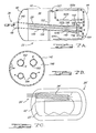
- FIG. 7A is a partially cutaway front plan view of the storage tank of FIG. 1 showing the common-access tube with flared end and the fluid flow lines passing therethrough;
- FIG. 7B is an end plan view along line 7 B- 7 B of FIG. 7A showing the attachment of the pipes within the common-access tube to the end plate on the flared end of the common-access tube;
- FIG. 8 is a perspective view of the corrugated piping used in the storage tank of FIG. 1 ;
- FIG. 9 is an end plan view of the tank of FIG. 1 showing the fluid piping that passes into the central tube;
- FIGS. 10A and 10B are simplified representations of the corrugations that can be utilized for the piping used in the storage tank of FIG. 1 ;
- FIG. 12 is a perspective view of one of the sectional stiffening members of FIG. 11 ;
- FIGS. 13A-F are cross-sectional views of various configurations for the annular stiffening members used in the storage tank of FIG. 1 ;
- FIGS. 14-17 are flowcharts of the various assembly steps for forming the storage tank of FIG. 1 .
- a plurality of insulation layers 30 are wrapped around the exterior of inner vessel 22 in the space between the inner and outer vessels 22 , 24 .
- a vacuum exists between inner and outer vessels 22 , 24 and within common-access tube 28 .
- the insulation layers 30 and the vacuum reduce heat influx into the interior of inner vessel 22 .
- Storage tank 20 can be used on mobile platforms, such as vehicles, or in stationary applications.
- inner vessel 22 includes a central segment 40 and a pair of end segments or end caps 42 , 44 .
- End caps 42 , 44 are welded to central segment 40 to define an interior space or volume 46 of inner vessel 22 .
- Common-access-tube 28 is attached, such as by welding to an opening in end cap 42 and extends from end cap 42 into interior 46 of inner vessel 22 .
- Common-access tube 28 is attached to end cap 42 prior to end cap 42 being welded to central segment 40 .
- fluid flow lines 26 are also positioned through and secured within common-access tube 28 prior to end cap 42 being welded to central segment 40 , as described below.
- a bracket 48 is attached, such as by welding, to an exterior of end cap 42 .
- a tensioning mechanism 50 is attached to end cap 44 . Bracket 48 and tensioning mechanism 50 provide attachment points for suspending inner vessel 22 within outer vessel 24 , as described below.
- Outer vessel 24 includes a central segment 60 and two end segments or end caps 62 , 64 that are welded to opposing ends of central segment 60 .
- Central segment 60 has a generally uniform wall thickness.
- a pair of annular stiffening members/rings 68 is welded to opposing end portions 70 of central segment 60 .
- Stiffening members 68 extend across the juncture of central segment 60 with end caps 62 , 64 , as shown in FIGS. 1 and 4 .
- Stiffening members 68 provide support for central segment 60 and limit deformation thereof due to the suspending of inner vessel 22 within outer vessel 24 , as described below.
- Stiffening members 68 due to the overlapping of the juncture of central segment 60 with end caps 62 , 64 , also serve to prevent sparks and other welding debris and gases from entering into the space between inner and outer vessels 22 , 24 and from contacting insulation layers 30 therein when welding end cap 62 , 64 to central segment 60 .
- stiffening members 68 can be attached to the exterior of central segment 60 , although all the benefits of the present invention may not be realized. The attachment of end caps 62 , 64 to central segment 60 provides additional support for central segment 60 and limits deformation thereof due to the suspending of inner vessel 22 within outer vessel 24 .
- Inner vessel 22 is suspended within outer vessel 24 with a plurality of suspension members 80 .
- a first group 82 of suspension members 80 is coupled to one end portion 70 of central segment 60 of outer vessel 24 and to end cap 42 of inner vessel 22 .
- a second group 84 of suspension members 80 is coupled to the other end portion 70 of central segment 60 of outer vessel 24 and to end cap 44 of inner vessel 22 .
- suspension members 80 are preferably in the form of closed-loop cords, individual strips or sections of cords that are not looped can also be utilized. Such cords would be secured to the appropriate attachment mechanisms coupled to the central segment 60 of outer vessel 24 and to end caps 42 , 44 of inner vessel 22 . It should also be appreciated that while three suspension members 80 are shown as being used to support each end of inner vessel 22 , a single continuous suspension member (not shown) could be utilized to support each end of inner vessel 22 by routing or wrapping each suspension member through the various attachment mechanisms associated with each side of storage tank 20 and providing three distinct tensile segments that extend between each end of inner vessel 22 and outer vessel 24 .
- each suspension member 80 of first and second groups 82 , 84 is wrapped around an associated roller 88 which is coupled to one of the stiffening members 68 on each end portion 70 of central segment 60 of outer vessel 24 by an associated bracket 90 and bolt 92 .
- Each suspension member 80 of first group 82 is also wrapped around an associated roller 94 coupled via a bolt 96 to bracket 48 attached to the axial center portion of end cap 42 of inner vessel 22 .
- a portion of common-access tube 28 could extend (not shown) outwardly beyond end cap 42 and provide an attachment point for rollers 94 in lieu of bracket 48 .
- Each suspension member 80 of second group 84 is also wrapped around an associated roller 100 which is coupled to tensioning mechanism 50 attached to end cap 44 of inner vessel 22 .
- bracket 48 and tensioning mechanism 50 are attached to axially center portions of each end cap 42 , 44 of inner vessel 22 to provide centralized support of inner vessel 22 within outer vessel 24 .
- a base plate 110 is attached to end cap 44 of inner vessel 22 , such as by welding.
- a movable plate 112 is axially movable relative to base plate 110 along fixed guides 114 .
- Bracket members 115 are fixedly attached to movable plate 112 .
- Rollers. 100 are bolted to bracket members 115 .
- a threaded adjusting member 116 extends through a threaded opening in movable plate 112 and contacts base plate 110 .
- the threaded engagement between adjusting member 116 and movable plate 112 translates rotation of adjusting member 116 into axial movement of movable plate 112 relative to base plate 110 along guides 114 .
- the tension in suspension members 80 will vary.
- an inner vessel assembly is positioned within central segment 60 of outer vessel 24 .
- the inner vessel assembly includes inner vessel 22 with insulation layers 30 wrapped thereon and fluid flow lines 26 extending outwardly from common-access tube 28 .
- the portions of fluid flow lines 26 that are exterior to inner vessel 22 can be configured into a desired shape or orientation prior to the positioning of the inner vessel assembly within central segment 60 . Alternately, the fluid flow lines 26 can remain straight or out of way and be bent into a desired configuration after suspending inner vessel 22 within outer vessel 24 .
- the suspension of the inner vessel assembly within outer vessel 24 is described in more detail below.
- suspension members 80 are intended to be under tensile loading at all times. While suspension members 80 may have a stiffness associated with their specific materials of construction, it should be appreciated that suspension members 80 are not intended to be subjected to any appreciable compressive loading. Suspension members 80 are sized to provide the required support of inner vessel 22 within outer vessel 24 and for the fluids to be stored within inner vessel 22 . Additionally, suspension members 80 are designed to be operable to withstand sudden accelerations/decelerations when storage tank 20 is located on a movable platform, such as a vehicle. Furthermore, the dimensions of suspension members 80 are designed to minimize the heat path into inner vessel 22 .
- the angle ⁇ at which suspension members 80 extend from their associated brackets on inner vessel 22 toward end portions 70 of central segment 60 of outer vessel 24 relative to the axial axis of inner vessel 22 provides differing amounts of axial support.
- the larger intrusion decreases the volume of storage tank 20 for a given size tank.
- the angle ⁇ is chosen based on one or more of these design considerations.
- Stiffening members 68 serve to reinforce central segment 60 of outer vessel 24 and limit the deformation of central segment 60 due to the suspension of inner vessel 22 within outer vessel 24 . Limiting the deformation facilitates the aligning and attachment of end caps 62 , 64 to central segment 60 . To accomplish this, brackets 90 are attached, such as by welding, directly to stiffening members 68 so that suspension members 80 directly impart their tensile loading on stiffening members 68 . The tensile load on stiffening members 68 is transmitted to central segment 60 and distributed along end portions 70 . Stiffening members 68 can take a variety of cross-sectional shapes. For example, as shown in FIGS.
- stiffening members 68 can be rectangular in cross-section with the longer side extending either axially or radially, respectively.
- the cross-section of stiffening member 68 can be L-shaped, as shown in FIG. 13C , T-shaped, as shown in FIG. 13D , I-shaped, as shown in FIG. 13E , and inverted U-shaped, as shown in FIG. 13F .
- Each of these different cross-sectional configurations will provide support for suspending inner vessel 22 within outer vessel 24 and limit the deformation of outer vessel 24 .
- the cross-sectional shapes shown for stiffening members 68 are merely exemplary and that other cross-sectional shapes or combinations thereof can be utilized. The particular cross-sectional shape chosen will vary depending upon the design needs of the particular storage tank 20 being built.
- FIGS. 11 and 12 an alternate configuration for the stiffening of outer vessel 24 is shown.
- three sectional stiffeners 120 are utilized on each end portion 70 of central segment 60 of outer vessel 24 .
- Sectional stiffeners 120 are disposed between the attachment points for suspension members 80 .
- Sectional stiffeners 120 serve to provide additional stiffening to the end portions 70 between suspension members 80 .
- Sectional stiffeners 120 are partially circular shaped in plan view and have a side edge 122 shaped to correspond to the interior of annular stiffening members 68 .
- Sectional stiffeners 120 are welded to stiffening members 68 to provide additional support thereto. It may be possible to use sectional stiffeners 120 in lieu of annular stiffening members 68 .
- central segment 60 of outer vessel 24 can be reinforced with annular stiffening members 68 , sectional stiffeners 120 or a combination of both.
- These stiffening features of the present invention provide localized support for specific portions of central segment 60 of outer vessel 24 during assembly. These stiffening features also provide localized support to both central segment 60 and end cap 62 , 64 during operation of storage tank 20 .
- end caps 62 , 64 to central segment 60 will also provide additional support for central segment 60 and support a portion of the load imparted by the suspension of inner vessel 22 therein.
- the use of such stiffening members advantageously provides the localized support and rigidity where necessary without increasing the wall thickness or structural rigidity of central segment 60 solely to allow the suspension of inner vessel 22 therein prior to the attachment of end caps 62 , 64 .
- the use of stiffening members enables the use of a central segment 60 having a thickness that is substantially uniform throughout its axial length.
- a first end 140 of common-access tube 28 is attached to end cap 42 of inner vessel 22 .
- a second end 142 of common-access tube 28 is cantilevered into interior 46 of inner vessel 22 .
- Common-access tube 28 has an axial length between first and second ends 140 , 142 .
- Common-access tube 28 has a first portion 144 with a substantially uniform diameter and a second (flared) portion 146 having a changing diameter. First and second portions 144 , 146 share a common axial axis.
- An end plate 148 is welded to second end 142 of common-access tube 28 and forms a fluid-tight seal therewith, as shown in FIG. 7B and indicated as W.
- a perforated end plate 150 (shown in FIG. 2 ) is disposed in first end 140 .
- Fluid flow lines 26 run through common-access tube 28 and into interior 46 of inner vessel 22 through end plates 148 , 150 .
- all fluid flow lines 26 enter interior 46 of inner vessel 22 through common-access tube 28 .
- all communication/data/power/etc. lines, such as wires, connectors and cables, such as those connecting to a level sensor 152 are also routed through common-access tube 28 within one or more of the fluid flow lines 26 .
- Level sensor 152 is attached to an exterior of common-access tube 28 and is within interior volume 46 of inner vessel 22 .
- Level sensor 152 is operable to provide a signal indicative of the liquid level within inner vessel 22 .
- the communication line 153 for level sensor 152 exits inner vessel 22 through one of the fluid flow lines 26 .
- the use of common-access tube 28 to route all the piping and communication/data/power/etc. lines into interior 46 of inner vessel 22 advantageously reduces the number of obstructions on the exterior of inner vessel 22 around which insulation layers 30 must be routed. Additionally, the number of heat flow shortcuts are reduced along with facilitating the automated application of insulation layers 30 .
- First end 140 is preferably attached to an axial center portion of end cap 42 of inner vessel 22 .
- This attachment location centralizes the obstruction caused by fluid flow lines 26 leaving inner vessel 22 and aligns with the bracket 48 used to attach first group 82 of suspension members 80 to end cap 42 of inner vessel 22 .
- the centralized aligning of these various features facilitates the wrapping of the insulation layers 30 , either manually or automated, which are generally wrapped in a tangential direction and folded over on the end caps 42 , 44 .
- Fluid flow lines 26 are spaced apart from the interior wall 154 of common-access tube 28 . Fluid flow lines 26 may touch one another or be spaced apart from one another within common-access tube 28 . Preferably, fluid flow lines 26 are spaced apart from one another. Fluid flow lines 26 diverge from one another in flared portion 146 to pass through end plate 148 in a spaced relation, as shown in FIG. 7B . Preferably, fluid flow lines 26 are evenly spaced apart when passing through end plate 148 . The spacing facilitates the fluid-tight welding of each fluid flow line 26 to end plate 148 . That is, the increased diameter of second portion 146 allows fluid flow lines 26 to be spaced apart a distance sufficient to manipulate a welding device around the perimeter of each fluid flow line 26 with limited interference caused by the adjacent fluid flow lines.
- the volume of interior 46 of inner vessel 22 occupied by common-access tube 28 is advantageously reduced with first portion 144 of common-access tube 28 having a smaller diameter than flared portion 146 . That is, if the entire length of common-access tube 28 were of a diameter sufficient to facilitate the welding of fluid flow lines 26 to end plate 148 with limited interference from each other, the overall volume of common-access tube 28 within interior 46 of inner vessel 22 would be increased. Increasing the volume of common-access tube 28 decreases the fluid-holding capacity of inner vessel 22 .
- Common-access tube 28 is angled such that second end 142 is nominally lower than first end 140 . This angling provides an advantageous temperature profile along the fluid flow lines 26 and common-access tube 28 wherein the colder fluid is at the lower elevation than the warmer fluid. This helps minimize parasitic heat leaks from natural convection inside fluid flow lines 26 .
- common-access tube 28 extends substantially the entire axial length of inner vessel 22 . By having common-access tube 28 extending as far as possible within inner vessel 22 , a maximization of the heat-resisting effective length can be realized.
- common-access tube 28 can extend within interior 46 of inner vessel 22 by the necessity of fluid flow lines 26 exiting end plate 148 and the space required to route fluid flow lines 26 to their appropriate locations within interior 46 of inner vessel 22 .
- common-access tube 28 ′ has a substantially uniform diameter and extends from a non-central portion of end cap 42 ′ of inner vessel 22 ′.
- This configuration advantageously routes all the fluid flow lines 26 ′ into interior volume 46 ′ of inner vessel 22 ′ through a single access location thereby minimizing the obstructions on the exterior of inner vessel 22 ′ that must be accommodated by the insulation layers 30 ′.
- the uniform diameter of common-access tube 28 ′ encompasses a greater volume of inner vessel 22 ′ than that of common-access tube 28 described above and shown in FIG. 7A .
- a common-access tube advantageously minimizes the interference with applying insulation layers 30 to inner vessel 22 . Additionally, use of a common-access tube also facilitates modular construction of cryogenic storage tank 20 , as described in more detail below. Moreover, the use of a common-access tube can advantageously provide a desired temperature profile and reduce heat paths into the inner vessel.
- Fluid flow lines 26 extend from the exterior of cryogenic storage tank 20 and outer vessel 24 into interior 46 of inner vessel 22 . Fluid flow lines 26 pass through openings in outer vessel 24 , through the space between inner and outer vessels 22 , 24 and into interior 46 of inner vessel 22 through common-access tube 28 . Fluid flow lines 26 include a variety of different flow lines that each performs a different purpose or function.
- a liquid fill line 160 is used to fill inner vessel 22 with the desired fluid, such as hydrogen, in liquid form.
- a gas extraction line 162 is used to extract the fluid from inner vessel 22 in a gaseous form.
- a heat exchange loop 164 can be used to facilitate the extraction of the fluid in gaseous form from inner vessel 22 .
- Heat exchange loop 164 is used to selectively route a heating fluid through interior 46 of inner vessel 22 . The routing of the heating fluid increases the temperature within inner vessel 22 , thereby increasing the gaseous portion of the fluid stored therein. Additionally, the use of heat exchange loop 164 can also facilitate the maintaining of a desired operational pressure within inner vessel 22 , thereby also facilitating the extraction of the fluid therefrom.
- a liquid extraction line (not shown) could be employed.
- the liquid extraction line would have an end terminating in the lower portion of central segment 40 of inner vessel 22 and be used to extract liquid from inner vessel 22 .
- an external heater can be used to convert the extracted liquid into gaseous form when it is desired to provide the fluid in gaseous form to a downstream component, such as a fuel cell stack or internal combustion engine.
- Each fluid flow line 26 can be comprised of a plurality of discrete, unitary and uninterrupted sections or segments that are attached together, such as by welding, to form the entire fluid flow line.
- each fluid flow line 160 , 162 , 164 can include respective interior segments 160 a , 162 a , 164 a that are within interior 46 of inner vessel 22 .
- Middle segments 160 b , 162 b , 164 b extend from their respective interior segments through common-access tube 28 and into the space between inner and outer vessels 22 , 24 .
- Exterior segments 160 c , 162 c , 164 c shown in FIGS.
- each segment a, b, c can be combined into a large single unitary uninterrupted segment that includes the interior, middle and exterior segments.
- unitary uninterrupted segment or fluid flow line means that that segment or fluid flow line is formed in a continuous manner and not by the attaching of discrete segments to one another.
- fluid flow lines 26 between inner and outer vessels 22 , 24 extend upwardly upon exiting common-access tube 28 , as shown in FIG. 9 , to avoid a siphoning effect and to provide an advantageous thermal profile.
- gas extraction line 162 or a liquid extraction line, if so equipped, can be wrapped around the exterior of inner vessel 22 in the space between inner and outer vessels 22 , 24 to help with the maintaining of the low temperature in inner vessel 22 during the extraction of the fluid from inner vessel 22 .
- each fluid flow line segment can include both corrugated portions and non-corrugated portions.
- one segment of piping such as that shown in FIG. 10A
- a different segment of fluid flow line can include multiple non-corrugated portions 172 disposed around a corrugated portion 170 .
- the number and location of corrugated portions 170 and non-corrugated portions 172 will vary depending upon the desired orientation of the particular fluid line segment when storage tank 20 is fully assembled.
- the corrugated portions can have varying gaps, heights and widths, as can be seen by comparing the corrugated portions 170 in FIG. 10A with the corrugated portions 170 in FIG. 10B . Additionally, the wall thickness of the particular fluid flow line can also vary. These various characteristics of corrugated portions 170 affect its stiffness and how easily it can be bent into a desired orientation. These characteristics also affect the maximum bend angle that can be imparted on that particular corrugated portion 170 .
- corrugated and non-corrugated portions 170 , 172 vary for particular segments of fluid flow lines
- type of corrugation can also vary to provide a fluid flow line segment that can be readily and easily bent into a desired orientation for assembly of storage tank 20 .
- each segment a, b, c of each fluid flow line 160 , 162 , 164 can have multiple corrugated and non-corrugated portions 170 , 172 .
- the corrugated portions 170 correspond to the locations where the various fluid flow lines are bent, such as at the end of the middle segment where the fluid lines flare away from each other to pass through end plate 148 of common-access tube 28 .
- the opposite ends of the middle segments can also have corrugated portions that facilitate the upward bending of these fluid flow lines in the space between the inner and outer vessels 22 , 24 .
- the interior segments 160 a , 162 a , 164 a of these various fluid flow lines can also have corrugated portions 170 and non-corrugated portions 172 that correspond to the various portions of the fluid flow lines that are bent or remain straight.
- non-corrugated portions 172 in each of the fluid flow line segments provides a level of stiffness or rigidity that is not available when only corrugated portions are used. These non-corrugated portions 172 thereby help to stiffen the fluid flow line segments and maintain the fluid flow line segments in their desired orientation during operation of storage tank 20 .
- the non-corrugated portions 172 also minimize and/or eliminate the need for additional bracing or framing to retain the fluid flow lines in their desired orientation during operation of storage tank 20 .
- by limiting the use of corrugated portions 170 to those areas that are required to be bent the potential for elongation of the various fluid flow lines due to pressure differentials during the operation of storage tank 20 is reduced.
- the use of fluid flow line segments having both corrugated and non-corrugated portions is advantageous over the use of an entirely corrugated segment.
- corrugated and non-corrugated portions 170 , 172 for the various segments of the fluid flow lines 26 also facilitates the assembly of storage tank 20 and, particularly, facilitates the construction of modular assemblies that can be used to form storage tank 20 .
- the various fluid flow lines 26 can be formed in straight and unbent segments with corrugated and non-corrugated portions 170 , 172 dispersed throughout its length. These various segments can then be attached to one or more components, such as common-access tube 28 at end plates 148 , 150 therein, or other fluid flow line segments to form a modular assembly.
- the modular assemblies can then be inserted into or attached to other components of storage tank 20 in a piecemeal fashion to form storage tank 20 , as described below.
- Storage tank 20 is formed by assembling inner vessel 22 and fluid flow lines 26 that extend into interior 46 of inner vessel 22 , as indicated in block 190 .
- the assembling of inner vessel 22 is shown in FIG. 15 .
- a modular assembly of common-access tube 28 , fluid flow lines 26 , sensor(s) and, optionally, end cap 42 is formed, as indicated in block 192 .
- There are two main ways to form this modular assembly as shown in blocks 194 and 196 . Either method shown in block 194 or 196 can be utilized.
- the spacing between the fluid flow lines 26 on end plate 148 prevents the fluid flow lines from interfering with each other during the welding process. If the fluid flow lines have not been pre-bent into a desired orientation, the fluid flow lines can then be bent into the proper orientation for subsequent running of the fluid flow lines through common-access tube 28 . To accomplish this, the corrugated portions 170 of the fluid flow lines can be bent so that the fluid flow lines will match the flared portion 146 and uniform diameter portion 144 of common-access tube 28 . With the fluid flow lines attached to end plate 148 and arranged into the desired orientation, the fluid flow lines are inserted through common-access tube 28 from the second end 142 , as indicated in block 194 b .
- fluid flow lines 26 are inserted through the opening(s) in end plate 150 on first end 140 of common-access tube 28 , if so equipped.
- End plate 148 is aligned with second end 142 and attached to common-access tube 28 by welding, as shown in FIG. 7B and as indicated in block 194 c .
- the fluid flow lines 26 can also be secured to end plate 150 , if so equipped.
- one way to attach fluid flow lines 26 to common-access tube 28 can be done by following the procedures indicated in block 194 .
- End plate 150 can then be positioned in the first end 140 of common-access tube 28 and attached thereto.
- the fluid flow lines 26 can also be secured to end plate 150 .
- a second way of assembling common-access tube 28 with fluid flow lines 26 can be achieved.
- first end 140 of common-access tube 28 is aligned with a central axial opening in end cap 42 with portions of fluid flow lines 26 extending through the opening in end cap 42 and through bracket 48 (if already attached). First end 140 is then welded to end cap 42 with common-access tube 28 at a desired angle relative to the axial axis of inner vessel 22 .
- each fluid flow line With the interior and middle segments of each fluid flow line secured to common-access tube 28 , the communication or signal lines for the various sensors that are to be disposed within interior 46 of inner vessel 22 can be routed through one of the fluid flow lines. It should be appreciated that the manufacturing steps performed in blocks 200 and 202 can be reversed in sequence, depending upon the desired order of construction. Regardless of the sequence in which the manufacturing of the modular assembly is conducted, a modular assembly that includes both the interior and middle segments of fluid flow lines 26 , common-access tube 28 , the internal sensors and end cap 42 are assembled together into a modular assembly and can be used to form inner vessel 22 . Specifically, the modular assembly is aligned with central segment 40 of inner vessel 22 and then attached thereto, such as by welding, as indicated in block 206 .
- Alignment of the modular assembly with central segment 40 can be performed by the use of jigs or other suspension mechanisms (not shown) to support and position the modular assembly in alignment with central segment 40 so that the welding of end cap 42 to central segment 40 is facilitated. If not already done, end cap 44 is aligned with central segment 40 and attached thereto, such as by welding, as indicated in block 208 . With these procedures complete, the assembly of inner vessel 22 is completed.
- inner vessel 22 can be positioned on a jig or other support structure (not shown).
- the insulation layers 30 are then wrapped, preferably in a tangential direction, around central segment 40 and end caps 42 , 44 .
- the application of the insulation layers can be manual or automated.
- the insulation layers are folded over end caps 42 , 44 and around the obstructions formed by bracket 48 and tensioning mechanism 50 .
- FIG. 16 a procedure to suspend inner vessel 22 within central segment 60 of outer vessel 24 is shown.
- Inner vessel 22 is positioned within central segment 60 of outer vessel 24 , as indicated in block 214 .
- a jig or other support structure (not shown) can be used to support inner vessel 22 when it is within central segment 60 prior to being suspended by suspension members 80 .
- first group 82 of suspension members 80 are attached to rollers 88 coupled to an associated stiffening member 68 and to rollers 94 on bracket 48 on end cap 42 , as indicated in block 216 .
- each roller 88 is inserted into the loop formed by a suspension member 80 and attached to its associated bracket 90 or stiffening member 68 .
- second group 84 of suspension members 80 are attached to the rollers 88 coupled to the associated stiffening member 68 and to also to rollers 100 on tensioning mechanism 50 , as indicated in block 218 . Again, this is accomplished by disposing each roller 88 within one of the suspension member loops 80 and attaching it to its associated bracket 90 on stiffening member 68 . Similarly, each roller 100 is also disposed within one of the suspension member loops 80 and attached to bracket member 115 . The fixed length of each suspension member loop 80 allows end 44 of inner vessel 22 to be suspended within the other end portion 70 of central segment 60 of outer vessel 24 .
- the jig or mechanism holding inner vessel 22 within outer vessel 24 can then be removed and inner vessel 22 suspended within central segment 60 by first and second groups 82 , 84 of suspension members 80 . It should be appreciated that the procedures indicated in blocks 216 and 218 can be done in the opposite order, if desired.
- tensioning mechanism 50 is then adjusted to apply a desired preloading or predetermined tension in suspension members 80 , as indicated in block 220 .
- adjusting member 116 is rotated to cause movable plate 112 to move relative to base plate 110 . Movement of movable plate 112 relative to base plate 110 should cause the tension in each suspension member of both first and second groups 82 , 84 to change. That is, because the suspension members extend both axially and radially relative to their associated connection to the ends 42 , 44 of inner vessel 22 , each suspension member imparts an axial and radial suspending force on the associated end of inner vessel 22 .
- FIG. 17 Another stage of manufacturing storage tanks 20 is the assembly of outer vessel 24 , as indicated in block 224 .
- the assembly procedure of outer vessel 24 is shown in FIG. 17 .
- the exterior segments of fluid flow lines 26 can be attached to the portion of the middle segments that extend out of common-access tube 28 with welds W, as indicated in block 230 .
- the middle segments extend beyond inner vessel 22 a distance sufficient to allow the welding of the exterior segments onto the middle segments without damaging or endangering insulation layers 30 .
- each exterior segment is welded to its associated middle segment, the portion of the middle segment extending out of common-access tube 28 and the exterior segments attached thereto can be bent into a predetermined orientation, as indicated in block 232 .
- the bending is facilitated by the existence of a variety of corrugated portions 170 and non-corrugated portions 172 in each of the segments of the fluid flow lines.
- the middle segments 160 b , 162 b , 164 b would extend outwardly beyond the common-access tube 28 and can be bent upwardly to provide a desired rise in elevation of these associated fluid flow lines 26 .
- the exterior segments 160 c , 162 c , 164 c could also be bent at their various corrugated portions 170 to provide a desired orientation, such as that shown in FIGS. 8 and 9 .
- the exterior segments 160 c , 162 c , 164 c can be routed through openings (not shown) in central segment 60 of outer vessel 24 and subsequently attached thereto, such as by welding. If desired, the various fluid flow lines can be mixed or matched between the two possibilities disclosed in blocks 234 and 236 . Due to the use of non-corrugated portions 172 between corrugated portions 170 , the stiffness of exterior segments 160 c , 162 c , 164 c should be sufficient to provide support for the fluid flow lines without requiring additional support or connection points/brackets.
- each fluid flow line could include discrete segments having both corrugated and non-corrugated portions and discrete segments that are free of corrugated portions.
- the various segments may include pre-bent segments and segments having corrugated and non-corrugated portions. Additionally, some segments could be pre-bent in some areas and have corrugated portions for subsequent bending during the assembly of storage tank 20 .
- the length of the various segments can vary and, in some cases, one or more of the fluid flow lines can be a single unitary uninterrupted flow line.
- the orientation of the fluid flow lines 26 is shown for one particular construction of a storage tank 20 . It should be appreciated that other final orientations for the fluid flow lines 26 can be employed, as necessitated by the design of storage tank 20 , without departing from the scope of the present invention. Moreover, it should be appreciated that common-access tube 28 could extend through a non-axial centered portion of an end-cap of inner vessel 22 , if desired, although all the benefits of the present invention may not be realized. Additionally, while the modular assembly is discussed as including specific components, it should be appreciated that additional components or less components can be assembled into a modular pre-assembly and then used to form various portions of storage tank 20 .
- the construction of the present invention facilitates the preparation of various modular components that can be made in one location and, if desired, moved to a second location for assembly into the remaining components to form storage tank 20 .
- the above description of the invention is merely exemplary in nature, and variations that do not depart from the gist of the invention are intended to within the scope of the invention. As such, such variations are not to be regarded as a departure from the spirit and scope of the invention.
Abstract
Description
Claims (11)
Priority Applications (2)
| Application Number | Priority Date | Filing Date | Title |
|---|---|---|---|
| US11/235,029 US8087534B2 (en) | 2005-09-26 | 2005-09-26 | Liquid hydrogen storage tank with partially-corrugated piping and method of manufacturing same |
| DE102006045119A DE102006045119B4 (en) | 2005-09-26 | 2006-09-25 | Liquid hydrogen storage tank with partially corrugated casing and method of manufacture |
Applications Claiming Priority (1)
| Application Number | Priority Date | Filing Date | Title |
|---|---|---|---|
| US11/235,029 US8087534B2 (en) | 2005-09-26 | 2005-09-26 | Liquid hydrogen storage tank with partially-corrugated piping and method of manufacturing same |
Publications (2)
| Publication Number | Publication Date |
|---|---|
| US20080000915A1 US20080000915A1 (en) | 2008-01-03 |
| US8087534B2 true US8087534B2 (en) | 2012-01-03 |
Family
ID=37905493
Family Applications (1)
| Application Number | Title | Priority Date | Filing Date |
|---|---|---|---|
| US11/235,029 Expired - Fee Related US8087534B2 (en) | 2005-09-26 | 2005-09-26 | Liquid hydrogen storage tank with partially-corrugated piping and method of manufacturing same |
Country Status (2)
| Country | Link |
|---|---|
| US (1) | US8087534B2 (en) |
| DE (1) | DE102006045119B4 (en) |
Families Citing this family (4)
| Publication number | Priority date | Publication date | Assignee | Title |
|---|---|---|---|---|
| US20070068951A1 (en) * | 2005-09-26 | 2007-03-29 | Manngmbh | Reservoir with a channel |
| FR2919912B1 (en) * | 2007-08-06 | 2009-11-27 | Air Liquide | CRYOGENIC FLUID RESERVOIR AND VEHICLE COMPRISING SUCH A RESERVOIR |
| WO2009023891A1 (en) * | 2007-08-22 | 2009-02-26 | Werner Hermeling | Device for storing and transporting cryogenic liquefied gases |
| FR3094069B1 (en) * | 2019-03-22 | 2021-10-29 | Ifp Energies Now | pressure tank with circumferential reinforcing elements |
Citations (24)
| Publication number | Priority date | Publication date | Assignee | Title |
|---|---|---|---|---|
| US2592974A (en) * | 1949-07-01 | 1952-04-15 | Gerard F Sulfrian | Suspension liquid gas container |
| US2777295A (en) | 1952-09-12 | 1957-01-15 | Union Carbide & Carbon Corp | Concrete reservoir for liquefied gases |
| US3134237A (en) * | 1960-12-21 | 1964-05-26 | Union Carbide Corp | Container for low-boiling liquefied gases |
| US3155265A (en) | 1964-11-03 | Thermal stress equalizing support system | ||
| FR1386918A (en) | 1963-04-24 | 1965-01-22 | Union Carbide Corp | Cryogenic apparatus |
| US3199715A (en) * | 1962-07-20 | 1965-08-10 | Union Carbide Corp | Insulation construction |
| US3201947A (en) | 1963-09-06 | 1965-08-24 | Little Inc A | Cryogenic transport tube incorporating liquefaction apparatus |
| US3319433A (en) | 1966-05-24 | 1967-05-16 | Ryan Ind Inc | Rectangular dewar |
| US3441164A (en) * | 1966-08-24 | 1969-04-29 | Union Carbide Corp | Cryogenic storage tanks |
| US4184609A (en) * | 1978-08-22 | 1980-01-22 | The United States Of America As Represented By The Administrator Of The National Aeronautics And Space Administration | Cryogenic container compound suspension strap |
| EP0178337A1 (en) | 1983-06-22 | 1986-04-23 | Union Carbide Corporation | Shipping container for storing materials at cryogenic temperatures |
| WO1989009860A1 (en) | 1988-04-15 | 1989-10-19 | Midwest Research Institute | Compact vacuum insulation |
| US4918627A (en) * | 1986-08-04 | 1990-04-17 | Fmc Corporation | Computer integrated gaging system |
| US5012948A (en) | 1989-06-21 | 1991-05-07 | General Dynamics Corporation, Convair Division | Support arrangement for a space based cryogenic vessel |
| US5130193A (en) | 1988-11-10 | 1992-07-14 | Nippon Oil Co., Ltd. | Fiber-reinforced composite cable |
| US5651473A (en) | 1992-11-12 | 1997-07-29 | Mve, Inc. | Support system for cryogenic vessels |
| EP0872684A2 (en) | 1997-04-14 | 1998-10-21 | General Electric Company | Passive conductor heater for zero boiloff superconducting magnet pressure control |
| US6509693B2 (en) * | 2000-09-06 | 2003-01-21 | Futaba Corporation | Filament for fluorescent display device |
| US20030150177A1 (en) * | 2000-11-08 | 2003-08-14 | Baratuci James Lynn | Ribbed tube continuous flexible spacer assembly |
| US6634519B2 (en) * | 2000-05-26 | 2003-10-21 | L'air Liquide - Societe Anonyme A Directoire Et Conseil De Surveillance Pour L'etude Et L'exploitation Des Procedes Georges Claude | Method for manufacturing a tank for a cryogenic fluid and tank thus produced |
| WO2004003441A1 (en) | 2002-06-26 | 2004-01-08 | Duksung Co., Ltd. | Cryovessel with gifford-mcmahon cryocooler and control method therefor |
| US20040195246A1 (en) | 2003-04-03 | 2004-10-07 | Rainer Immel | Construction for multi-layered vacuum super insulated cryogenic tank |
| US7293418B2 (en) * | 2001-11-30 | 2007-11-13 | Westport Power Inc. | Method and apparatus for delivering a high pressure gas from a cryogenic storage tank |
| US7344045B2 (en) * | 2003-09-23 | 2008-03-18 | Westport Power Inc. | Container for holding a cryogenic fluid |
-
2005
- 2005-09-26 US US11/235,029 patent/US8087534B2/en not_active Expired - Fee Related
-
2006
- 2006-09-25 DE DE102006045119A patent/DE102006045119B4/en not_active Expired - Fee Related
Patent Citations (27)
| Publication number | Priority date | Publication date | Assignee | Title |
|---|---|---|---|---|
| US3155265A (en) | 1964-11-03 | Thermal stress equalizing support system | ||
| US2592974A (en) * | 1949-07-01 | 1952-04-15 | Gerard F Sulfrian | Suspension liquid gas container |
| US2777295A (en) | 1952-09-12 | 1957-01-15 | Union Carbide & Carbon Corp | Concrete reservoir for liquefied gases |
| US3134237A (en) * | 1960-12-21 | 1964-05-26 | Union Carbide Corp | Container for low-boiling liquefied gases |
| US3199715A (en) * | 1962-07-20 | 1965-08-10 | Union Carbide Corp | Insulation construction |
| FR1386918A (en) | 1963-04-24 | 1965-01-22 | Union Carbide Corp | Cryogenic apparatus |
| US3178897A (en) | 1963-04-24 | 1965-04-20 | Union Carbide Corp | Cryogenic apparatus |
| US3201947A (en) | 1963-09-06 | 1965-08-24 | Little Inc A | Cryogenic transport tube incorporating liquefaction apparatus |
| DE1245998B (en) | 1963-09-06 | 1967-08-03 | Arthur D. Little, Inc., Cambridge, Mass. (V. St. A.) | Device for liquefying gases such as helium |
| US3319433A (en) | 1966-05-24 | 1967-05-16 | Ryan Ind Inc | Rectangular dewar |
| US3441164A (en) * | 1966-08-24 | 1969-04-29 | Union Carbide Corp | Cryogenic storage tanks |
| US4184609A (en) * | 1978-08-22 | 1980-01-22 | The United States Of America As Represented By The Administrator Of The National Aeronautics And Space Administration | Cryogenic container compound suspension strap |
| EP0178337A1 (en) | 1983-06-22 | 1986-04-23 | Union Carbide Corporation | Shipping container for storing materials at cryogenic temperatures |
| US4918627A (en) * | 1986-08-04 | 1990-04-17 | Fmc Corporation | Computer integrated gaging system |
| WO1989009860A1 (en) | 1988-04-15 | 1989-10-19 | Midwest Research Institute | Compact vacuum insulation |
| DE68928547T2 (en) | 1988-04-15 | 1998-04-23 | David Benson | COMPACT VACUUM ISOLATION |
| US5130193A (en) | 1988-11-10 | 1992-07-14 | Nippon Oil Co., Ltd. | Fiber-reinforced composite cable |
| US5012948A (en) | 1989-06-21 | 1991-05-07 | General Dynamics Corporation, Convair Division | Support arrangement for a space based cryogenic vessel |
| US5651473A (en) | 1992-11-12 | 1997-07-29 | Mve, Inc. | Support system for cryogenic vessels |
| EP0872684A2 (en) | 1997-04-14 | 1998-10-21 | General Electric Company | Passive conductor heater for zero boiloff superconducting magnet pressure control |
| US6634519B2 (en) * | 2000-05-26 | 2003-10-21 | L'air Liquide - Societe Anonyme A Directoire Et Conseil De Surveillance Pour L'etude Et L'exploitation Des Procedes Georges Claude | Method for manufacturing a tank for a cryogenic fluid and tank thus produced |
| US6509693B2 (en) * | 2000-09-06 | 2003-01-21 | Futaba Corporation | Filament for fluorescent display device |
| US20030150177A1 (en) * | 2000-11-08 | 2003-08-14 | Baratuci James Lynn | Ribbed tube continuous flexible spacer assembly |
| US7293418B2 (en) * | 2001-11-30 | 2007-11-13 | Westport Power Inc. | Method and apparatus for delivering a high pressure gas from a cryogenic storage tank |
| WO2004003441A1 (en) | 2002-06-26 | 2004-01-08 | Duksung Co., Ltd. | Cryovessel with gifford-mcmahon cryocooler and control method therefor |
| US20040195246A1 (en) | 2003-04-03 | 2004-10-07 | Rainer Immel | Construction for multi-layered vacuum super insulated cryogenic tank |
| US7344045B2 (en) * | 2003-09-23 | 2008-03-18 | Westport Power Inc. | Container for holding a cryogenic fluid |
Non-Patent Citations (4)
| Title |
|---|
| U.S. Appl. No. 11/235,030, filed Sep. 2005, Rainer Immel. |
| U.S. Appl. No. 11/235,031, filed Sep. 2005, Immel et al. |
| U.S. Appl. No. 11/235,035, filed Sep. 2005, DaSilva et al. |
| U.S. Appl. No. 11/235,058, filed Sep. 2005, Immel et al. |
Also Published As
| Publication number | Publication date |
|---|---|
| DE102006045119A1 (en) | 2007-04-26 |
| DE102006045119B4 (en) | 2009-04-16 |
| US20080000915A1 (en) | 2008-01-03 |
Similar Documents
| Publication | Publication Date | Title |
|---|---|---|
| US7641068B2 (en) | Liquid hydrogen storage tank with common-access tube as port for pipes into the inner vessel | |
| US7757882B2 (en) | Suspended liquid hydrogen storage tank | |
| US8162167B2 (en) | Modular construction of a liquid hydrogen storage tank with a common-access tube and method of assembling same | |
| US7721513B2 (en) | Construction for multi-layered vacuum super insulated cryogenic tank | |
| US8087534B2 (en) | Liquid hydrogen storage tank with partially-corrugated piping and method of manufacturing same | |
| JP6054359B2 (en) | Hose assembly for low temperature fluid transfer | |
| US7854241B2 (en) | Metal-clad insulating complex for a pipe | |
| JP2006525483A (en) | Light weight and compact heat insulation system | |
| US7717287B2 (en) | Liquid hydrogen storage tank with radial stiffening | |
| KR20200013222A (en) | Leaktight wall with reinforced corrugated membrane | |
| KR20190075657A (en) | connection structure of vacuum line | |
| KR20060037284A (en) | Cryogenic fluid tank and use in a motor vehicle | |
| JP2008196575A (en) | Hydrogen storage tank | |
| CN115552166A (en) | Liquid dome comprising an opening for a liquefied gas storage tank provided with an additional lid | |
| KR101485110B1 (en) | Apparatus of storing container for liquefied natural gas | |
| JP6307289B2 (en) | Heat exchanger and hydrogen storage device | |
| CN116857553B (en) | Cryogenic composite pipeline and application thereof | |
| JP2005003347A (en) | Meandering pipe with fin and air heating-type liquefied gas vaporizer using this pipe | |
| CN218000819U (en) | High-pressure vacuum pipeline | |
| JP2005069304A (en) | Air-temperature type liquified gas vaporizer | |
| JPS5817199Y2 (en) | Tank for cryogenic liquid storage | |
| KR20230062580A (en) | Insulated tanks with integrated or operably linked support systems | |
| KR20220077375A (en) | Expanding joint of liquid hydrogen transfer vacuum insulated pipe | |
| US2755819A (en) | Variable capacity reservoir | |
| KR20120035671A (en) | Anti-sloshing apparatus |
Legal Events
| Date | Code | Title | Description |
|---|---|---|---|
| AS | Assignment |
Owner name: GM GLOBAL TECHNOLOGY OPERATIONS, INC., MICHIGAN Free format text: ASSIGNMENT OF ASSIGNORS INTEREST;ASSIGNORS:DA SILVA, JADER MATOS;IMMEL, RAINER;REEL/FRAME:017044/0625;SIGNING DATES FROM 20050816 TO 20050817 Owner name: GM GLOBAL TECHNOLOGY OPERATIONS, INC., MICHIGAN Free format text: ASSIGNMENT OF ASSIGNORS INTEREST;ASSIGNORS:DA SILVA, JADER MATOS;IMMEL, RAINER;SIGNING DATES FROM 20050816 TO 20050817;REEL/FRAME:017044/0625 |
|
| AS | Assignment |
Owner name: UNITED STATES DEPARTMENT OF THE TREASURY, DISTRICT Free format text: SECURITY AGREEMENT;ASSIGNOR:GM GLOBAL TECHNOLOGY OPERATIONS, INC.;REEL/FRAME:022195/0334 Effective date: 20081231 Owner name: UNITED STATES DEPARTMENT OF THE TREASURY,DISTRICT Free format text: SECURITY AGREEMENT;ASSIGNOR:GM GLOBAL TECHNOLOGY OPERATIONS, INC.;REEL/FRAME:022195/0334 Effective date: 20081231 |
|
| AS | Assignment |
Owner name: CITICORP USA, INC. AS AGENT FOR BANK PRIORITY SECU Free format text: SECURITY AGREEMENT;ASSIGNOR:GM GLOBAL TECHNOLOGY OPERATIONS, INC.;REEL/FRAME:022553/0493 Effective date: 20090409 Owner name: CITICORP USA, INC. AS AGENT FOR HEDGE PRIORITY SEC Free format text: SECURITY AGREEMENT;ASSIGNOR:GM GLOBAL TECHNOLOGY OPERATIONS, INC.;REEL/FRAME:022553/0493 Effective date: 20090409 |
|
| AS | Assignment |
Owner name: GM GLOBAL TECHNOLOGY OPERATIONS, INC., MICHIGAN Free format text: RELEASE BY SECURED PARTY;ASSIGNOR:UNITED STATES DEPARTMENT OF THE TREASURY;REEL/FRAME:023124/0519 Effective date: 20090709 Owner name: GM GLOBAL TECHNOLOGY OPERATIONS, INC.,MICHIGAN Free format text: RELEASE BY SECURED PARTY;ASSIGNOR:UNITED STATES DEPARTMENT OF THE TREASURY;REEL/FRAME:023124/0519 Effective date: 20090709 |
|
| AS | Assignment |
Owner name: GM GLOBAL TECHNOLOGY OPERATIONS, INC., MICHIGAN Free format text: RELEASE BY SECURED PARTY;ASSIGNORS:CITICORP USA, INC. AS AGENT FOR BANK PRIORITY SECURED PARTIES;CITICORP USA, INC. AS AGENT FOR HEDGE PRIORITY SECURED PARTIES;REEL/FRAME:023127/0402 Effective date: 20090814 Owner name: GM GLOBAL TECHNOLOGY OPERATIONS, INC.,MICHIGAN Free format text: RELEASE BY SECURED PARTY;ASSIGNORS:CITICORP USA, INC. AS AGENT FOR BANK PRIORITY SECURED PARTIES;CITICORP USA, INC. AS AGENT FOR HEDGE PRIORITY SECURED PARTIES;REEL/FRAME:023127/0402 Effective date: 20090814 |
|
| AS | Assignment |
Owner name: UNITED STATES DEPARTMENT OF THE TREASURY, DISTRICT Free format text: SECURITY AGREEMENT;ASSIGNOR:GM GLOBAL TECHNOLOGY OPERATIONS, INC.;REEL/FRAME:023156/0142 Effective date: 20090710 Owner name: UNITED STATES DEPARTMENT OF THE TREASURY,DISTRICT Free format text: SECURITY AGREEMENT;ASSIGNOR:GM GLOBAL TECHNOLOGY OPERATIONS, INC.;REEL/FRAME:023156/0142 Effective date: 20090710 |
|
| AS | Assignment |
Owner name: UAW RETIREE MEDICAL BENEFITS TRUST, MICHIGAN Free format text: SECURITY AGREEMENT;ASSIGNOR:GM GLOBAL TECHNOLOGY OPERATIONS, INC.;REEL/FRAME:023162/0093 Effective date: 20090710 Owner name: UAW RETIREE MEDICAL BENEFITS TRUST,MICHIGAN Free format text: SECURITY AGREEMENT;ASSIGNOR:GM GLOBAL TECHNOLOGY OPERATIONS, INC.;REEL/FRAME:023162/0093 Effective date: 20090710 |
|
| FEPP | Fee payment procedure |
Free format text: PAYOR NUMBER ASSIGNED (ORIGINAL EVENT CODE: ASPN); ENTITY STATUS OF PATENT OWNER: LARGE ENTITY |
|
| AS | Assignment |
Owner name: GM GLOBAL TECHNOLOGY OPERATIONS, INC., MICHIGAN Free format text: RELEASE BY SECURED PARTY;ASSIGNOR:UNITED STATES DEPARTMENT OF THE TREASURY;REEL/FRAME:025245/0587 Effective date: 20100420 |
|
| AS | Assignment |
Owner name: GM GLOBAL TECHNOLOGY OPERATIONS, INC., MICHIGAN Free format text: RELEASE BY SECURED PARTY;ASSIGNOR:UAW RETIREE MEDICAL BENEFITS TRUST;REEL/FRAME:025314/0901 Effective date: 20101026 |
|
| AS | Assignment |
Owner name: WILMINGTON TRUST COMPANY, DELAWARE Free format text: SECURITY AGREEMENT;ASSIGNOR:GM GLOBAL TECHNOLOGY OPERATIONS, INC.;REEL/FRAME:025327/0041 Effective date: 20101027 |
|
| AS | Assignment |
Owner name: GM GLOBAL TECHNOLOGY OPERATIONS LLC, MICHIGAN Free format text: CHANGE OF NAME;ASSIGNOR:GM GLOBAL TECHNOLOGY OPERATIONS, INC.;REEL/FRAME:025780/0936 Effective date: 20101202 |
|
| ZAAA | Notice of allowance and fees due |
Free format text: ORIGINAL CODE: NOA |
|
| ZAAB | Notice of allowance mailed |
Free format text: ORIGINAL CODE: MN/=. |
|
| STCF | Information on status: patent grant |
Free format text: PATENTED CASE |
|
| AS | Assignment |
Owner name: GM GLOBAL TECHNOLOGY OPERATIONS LLC, MICHIGAN Free format text: RELEASE BY SECURED PARTY;ASSIGNOR:WILMINGTON TRUST COMPANY;REEL/FRAME:034184/0001 Effective date: 20141017 |
|
| FPAY | Fee payment |
Year of fee payment: 4 |
|
| MAFP | Maintenance fee payment |
Free format text: PAYMENT OF MAINTENANCE FEE, 8TH YEAR, LARGE ENTITY (ORIGINAL EVENT CODE: M1552); ENTITY STATUS OF PATENT OWNER: LARGE ENTITY Year of fee payment: 8 |
|
| FEPP | Fee payment procedure |
Free format text: MAINTENANCE FEE REMINDER MAILED (ORIGINAL EVENT CODE: REM.); ENTITY STATUS OF PATENT OWNER: LARGE ENTITY |
|
| LAPS | Lapse for failure to pay maintenance fees |
Free format text: PATENT EXPIRED FOR FAILURE TO PAY MAINTENANCE FEES (ORIGINAL EVENT CODE: EXP.); ENTITY STATUS OF PATENT OWNER: LARGE ENTITY |
|
| STCH | Information on status: patent discontinuation |
Free format text: PATENT EXPIRED DUE TO NONPAYMENT OF MAINTENANCE FEES UNDER 37 CFR 1.362 |
|
| FP | Lapsed due to failure to pay maintenance fee |
Effective date: 20240103 |