US8089248B2 - Battery monitoring and control system and method of use including redundant secondary communication interface - Google Patents
Battery monitoring and control system and method of use including redundant secondary communication interface Download PDFInfo
- Publication number
- US8089248B2 US8089248B2 US12/421,572 US42157209A US8089248B2 US 8089248 B2 US8089248 B2 US 8089248B2 US 42157209 A US42157209 A US 42157209A US 8089248 B2 US8089248 B2 US 8089248B2
- Authority
- US
- United States
- Prior art keywords
- battery
- interface
- node
- primary
- battery monitor
- Prior art date
- Legal status (The legal status is an assumption and is not a legal conclusion. Google has not performed a legal analysis and makes no representation as to the accuracy of the status listed.)
- Active, expires
Links
Images


Classifications
-
- H—ELECTRICITY
- H02—GENERATION; CONVERSION OR DISTRIBUTION OF ELECTRIC POWER
- H02J—CIRCUIT ARRANGEMENTS OR SYSTEMS FOR SUPPLYING OR DISTRIBUTING ELECTRIC POWER; SYSTEMS FOR STORING ELECTRIC ENERGY
- H02J7/00—Circuit arrangements for charging or depolarising batteries or for supplying loads from batteries
- H02J7/0013—Circuit arrangements for charging or depolarising batteries or for supplying loads from batteries acting upon several batteries simultaneously or sequentially
- H02J7/0014—Circuits for equalisation of charge between batteries
-
- B—PERFORMING OPERATIONS; TRANSPORTING
- B60—VEHICLES IN GENERAL
- B60L—PROPULSION OF ELECTRICALLY-PROPELLED VEHICLES; SUPPLYING ELECTRIC POWER FOR AUXILIARY EQUIPMENT OF ELECTRICALLY-PROPELLED VEHICLES; ELECTRODYNAMIC BRAKE SYSTEMS FOR VEHICLES IN GENERAL; MAGNETIC SUSPENSION OR LEVITATION FOR VEHICLES; MONITORING OPERATING VARIABLES OF ELECTRICALLY-PROPELLED VEHICLES; ELECTRIC SAFETY DEVICES FOR ELECTRICALLY-PROPELLED VEHICLES
- B60L3/00—Electric devices on electrically-propelled vehicles for safety purposes; Monitoring operating variables, e.g. speed, deceleration or energy consumption
- B60L3/0023—Detecting, eliminating, remedying or compensating for drive train abnormalities, e.g. failures within the drive train
- B60L3/0046—Detecting, eliminating, remedying or compensating for drive train abnormalities, e.g. failures within the drive train relating to electric energy storage systems, e.g. batteries or capacitors
-
- B—PERFORMING OPERATIONS; TRANSPORTING
- B60—VEHICLES IN GENERAL
- B60L—PROPULSION OF ELECTRICALLY-PROPELLED VEHICLES; SUPPLYING ELECTRIC POWER FOR AUXILIARY EQUIPMENT OF ELECTRICALLY-PROPELLED VEHICLES; ELECTRODYNAMIC BRAKE SYSTEMS FOR VEHICLES IN GENERAL; MAGNETIC SUSPENSION OR LEVITATION FOR VEHICLES; MONITORING OPERATING VARIABLES OF ELECTRICALLY-PROPELLED VEHICLES; ELECTRIC SAFETY DEVICES FOR ELECTRICALLY-PROPELLED VEHICLES
- B60L58/00—Methods or circuit arrangements for monitoring or controlling batteries or fuel cells, specially adapted for electric vehicles
- B60L58/10—Methods or circuit arrangements for monitoring or controlling batteries or fuel cells, specially adapted for electric vehicles for monitoring or controlling batteries
- B60L58/12—Methods or circuit arrangements for monitoring or controlling batteries or fuel cells, specially adapted for electric vehicles for monitoring or controlling batteries responding to state of charge [SoC]
-
- B—PERFORMING OPERATIONS; TRANSPORTING
- B60—VEHICLES IN GENERAL
- B60L—PROPULSION OF ELECTRICALLY-PROPELLED VEHICLES; SUPPLYING ELECTRIC POWER FOR AUXILIARY EQUIPMENT OF ELECTRICALLY-PROPELLED VEHICLES; ELECTRODYNAMIC BRAKE SYSTEMS FOR VEHICLES IN GENERAL; MAGNETIC SUSPENSION OR LEVITATION FOR VEHICLES; MONITORING OPERATING VARIABLES OF ELECTRICALLY-PROPELLED VEHICLES; ELECTRIC SAFETY DEVICES FOR ELECTRICALLY-PROPELLED VEHICLES
- B60L58/00—Methods or circuit arrangements for monitoring or controlling batteries or fuel cells, specially adapted for electric vehicles
- B60L58/10—Methods or circuit arrangements for monitoring or controlling batteries or fuel cells, specially adapted for electric vehicles for monitoring or controlling batteries
- B60L58/18—Methods or circuit arrangements for monitoring or controlling batteries or fuel cells, specially adapted for electric vehicles for monitoring or controlling batteries of two or more battery modules
- B60L58/21—Methods or circuit arrangements for monitoring or controlling batteries or fuel cells, specially adapted for electric vehicles for monitoring or controlling batteries of two or more battery modules having the same nominal voltage
-
- B—PERFORMING OPERATIONS; TRANSPORTING
- B60—VEHICLES IN GENERAL
- B60L—PROPULSION OF ELECTRICALLY-PROPELLED VEHICLES; SUPPLYING ELECTRIC POWER FOR AUXILIARY EQUIPMENT OF ELECTRICALLY-PROPELLED VEHICLES; ELECTRODYNAMIC BRAKE SYSTEMS FOR VEHICLES IN GENERAL; MAGNETIC SUSPENSION OR LEVITATION FOR VEHICLES; MONITORING OPERATING VARIABLES OF ELECTRICALLY-PROPELLED VEHICLES; ELECTRIC SAFETY DEVICES FOR ELECTRICALLY-PROPELLED VEHICLES
- B60L58/00—Methods or circuit arrangements for monitoring or controlling batteries or fuel cells, specially adapted for electric vehicles
- B60L58/10—Methods or circuit arrangements for monitoring or controlling batteries or fuel cells, specially adapted for electric vehicles for monitoring or controlling batteries
- B60L58/18—Methods or circuit arrangements for monitoring or controlling batteries or fuel cells, specially adapted for electric vehicles for monitoring or controlling batteries of two or more battery modules
- B60L58/22—Balancing the charge of battery modules
-
- H—ELECTRICITY
- H01—ELECTRIC ELEMENTS
- H01M—PROCESSES OR MEANS, e.g. BATTERIES, FOR THE DIRECT CONVERSION OF CHEMICAL ENERGY INTO ELECTRICAL ENERGY
- H01M10/00—Secondary cells; Manufacture thereof
- H01M10/42—Methods or arrangements for servicing or maintenance of secondary cells or secondary half-cells
- H01M10/4207—Methods or arrangements for servicing or maintenance of secondary cells or secondary half-cells for several batteries or cells simultaneously or sequentially
-
- H—ELECTRICITY
- H01—ELECTRIC ELEMENTS
- H01M—PROCESSES OR MEANS, e.g. BATTERIES, FOR THE DIRECT CONVERSION OF CHEMICAL ENERGY INTO ELECTRICAL ENERGY
- H01M10/00—Secondary cells; Manufacture thereof
- H01M10/42—Methods or arrangements for servicing or maintenance of secondary cells or secondary half-cells
- H01M10/44—Methods for charging or discharging
- H01M10/441—Methods for charging or discharging for several batteries or cells simultaneously or sequentially
-
- H—ELECTRICITY
- H02—GENERATION; CONVERSION OR DISTRIBUTION OF ELECTRIC POWER
- H02J—CIRCUIT ARRANGEMENTS OR SYSTEMS FOR SUPPLYING OR DISTRIBUTING ELECTRIC POWER; SYSTEMS FOR STORING ELECTRIC ENERGY
- H02J7/00—Circuit arrangements for charging or depolarising batteries or for supplying loads from batteries
- H02J7/0047—Circuit arrangements for charging or depolarising batteries or for supplying loads from batteries with monitoring or indicating devices or circuits
-
- H—ELECTRICITY
- H04—ELECTRIC COMMUNICATION TECHNIQUE
- H04Q—SELECTING
- H04Q9/00—Arrangements in telecontrol or telemetry systems for selectively calling a substation from a main station, in which substation desired apparatus is selected for applying a control signal thereto or for obtaining measured values therefrom
-
- B—PERFORMING OPERATIONS; TRANSPORTING
- B60—VEHICLES IN GENERAL
- B60L—PROPULSION OF ELECTRICALLY-PROPELLED VEHICLES; SUPPLYING ELECTRIC POWER FOR AUXILIARY EQUIPMENT OF ELECTRICALLY-PROPELLED VEHICLES; ELECTRODYNAMIC BRAKE SYSTEMS FOR VEHICLES IN GENERAL; MAGNETIC SUSPENSION OR LEVITATION FOR VEHICLES; MONITORING OPERATING VARIABLES OF ELECTRICALLY-PROPELLED VEHICLES; ELECTRIC SAFETY DEVICES FOR ELECTRICALLY-PROPELLED VEHICLES
- B60L2240/00—Control parameters of input or output; Target parameters
- B60L2240/40—Drive Train control parameters
- B60L2240/54—Drive Train control parameters related to batteries
- B60L2240/547—Voltage
-
- B—PERFORMING OPERATIONS; TRANSPORTING
- B60—VEHICLES IN GENERAL
- B60L—PROPULSION OF ELECTRICALLY-PROPELLED VEHICLES; SUPPLYING ELECTRIC POWER FOR AUXILIARY EQUIPMENT OF ELECTRICALLY-PROPELLED VEHICLES; ELECTRODYNAMIC BRAKE SYSTEMS FOR VEHICLES IN GENERAL; MAGNETIC SUSPENSION OR LEVITATION FOR VEHICLES; MONITORING OPERATING VARIABLES OF ELECTRICALLY-PROPELLED VEHICLES; ELECTRIC SAFETY DEVICES FOR ELECTRICALLY-PROPELLED VEHICLES
- B60L2240/00—Control parameters of input or output; Target parameters
- B60L2240/40—Drive Train control parameters
- B60L2240/54—Drive Train control parameters related to batteries
- B60L2240/549—Current
-
- H—ELECTRICITY
- H04—ELECTRIC COMMUNICATION TECHNIQUE
- H04Q—SELECTING
- H04Q2209/00—Arrangements in telecontrol or telemetry systems
- H04Q2209/30—Arrangements in telecontrol or telemetry systems using a wired architecture
-
- Y—GENERAL TAGGING OF NEW TECHNOLOGICAL DEVELOPMENTS; GENERAL TAGGING OF CROSS-SECTIONAL TECHNOLOGIES SPANNING OVER SEVERAL SECTIONS OF THE IPC; TECHNICAL SUBJECTS COVERED BY FORMER USPC CROSS-REFERENCE ART COLLECTIONS [XRACs] AND DIGESTS
- Y02—TECHNOLOGIES OR APPLICATIONS FOR MITIGATION OR ADAPTATION AGAINST CLIMATE CHANGE
- Y02E—REDUCTION OF GREENHOUSE GAS [GHG] EMISSIONS, RELATED TO ENERGY GENERATION, TRANSMISSION OR DISTRIBUTION
- Y02E60/00—Enabling technologies; Technologies with a potential or indirect contribution to GHG emissions mitigation
- Y02E60/10—Energy storage using batteries
-
- Y—GENERAL TAGGING OF NEW TECHNOLOGICAL DEVELOPMENTS; GENERAL TAGGING OF CROSS-SECTIONAL TECHNOLOGIES SPANNING OVER SEVERAL SECTIONS OF THE IPC; TECHNICAL SUBJECTS COVERED BY FORMER USPC CROSS-REFERENCE ART COLLECTIONS [XRACs] AND DIGESTS
- Y02—TECHNOLOGIES OR APPLICATIONS FOR MITIGATION OR ADAPTATION AGAINST CLIMATE CHANGE
- Y02T—CLIMATE CHANGE MITIGATION TECHNOLOGIES RELATED TO TRANSPORTATION
- Y02T10/00—Road transport of goods or passengers
- Y02T10/60—Other road transportation technologies with climate change mitigation effect
- Y02T10/70—Energy storage systems for electromobility, e.g. batteries
-
- Y—GENERAL TAGGING OF NEW TECHNOLOGICAL DEVELOPMENTS; GENERAL TAGGING OF CROSS-SECTIONAL TECHNOLOGIES SPANNING OVER SEVERAL SECTIONS OF THE IPC; TECHNICAL SUBJECTS COVERED BY FORMER USPC CROSS-REFERENCE ART COLLECTIONS [XRACs] AND DIGESTS
- Y02—TECHNOLOGIES OR APPLICATIONS FOR MITIGATION OR ADAPTATION AGAINST CLIMATE CHANGE
- Y02T—CLIMATE CHANGE MITIGATION TECHNOLOGIES RELATED TO TRANSPORTATION
- Y02T90/00—Enabling technologies or technologies with a potential or indirect contribution to GHG emissions mitigation
- Y02T90/10—Technologies relating to charging of electric vehicles
- Y02T90/16—Information or communication technologies improving the operation of electric vehicles
Definitions
- the present invention relates generally to monitoring and controlling a battery system and providing a link between a plurality of batteries and more particularly to a method of monitoring a redundant link between batteries and associated integrated circuit (IC) battery modules.
- IC integrated circuit
- Battery electronics for batteries associated with electric or hybrid vehicles present several challenges in managing the connections between batteries, as well as monitoring and managing battery output.
- Existing IC battery monitor chip architecture includes either a serial or a parallel communication link from the battery monitor chip to a system controller, the system controller coordinating all battery monitor chips in a system and gathering data therefrom while also controlling charge balancing of the individual batteries.
- each respective battery monitor chip is in signal communication with the system controller.
- serial daisy chain a circuit in the battery system is created whereby if any of the electrical connections included in the serial link between each respective battery monitor chip of the plurality of battery monitor chips in a “serial daisy chain” form an open-circuit or a short-circuit to an adjacent node, then serial communication fails for each battery monitor chip on the serial chain.
- FIG. 1 illustrates a prior art system of linking a plurality of battery monitor chips.
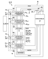
- FIG. 2 illustrates a battery monitoring and control system including plurality of battery monitor modules and chips in serial communication with a system controller and with each other in accordance with one embodiment of the invention.
- FIG. 3 illustrates a detailed view of two battery monitor chips each having a primary and a secondary communication interface each respectively linked to a primary and a secondary battery communication link in accordance with one embodiment of the invention.
- FIG. 4 is a flow chart illustrating a method of using a battery monitoring and control system.
- FIG. 5 is a flow chart illustrating a method of determining functionality of a Serial Peripheral Interface (SPI) in accordance with one embodiment of the invention.
- SPI Serial Peripheral Interface
- FIG. 6 is a flow chart illustrating a method of determining functionality of a Universal Asynchronous Receiver/Transmitter (UART) in accordance with one embodiment of the invention.
- UART Universal Asynchronous Receiver/Transmitter
- FIG. 7 is a flow chart illustrating a method of selecting a communication link in accordance with one embodiment of the invention.
- FIG. 8 is a flow chart illustrating a method of providing notification to a user if system functionality is reduced in accordance with one embodiment of the invention.
- FIG. 9 is a flow chart illustrating a method of implementing a Limited Operational Strategy (LOS) in accordance with one embodiment of the invention.
- LOS Limited Operational Strategy
- a battery monitoring and control system includes at least one battery cell operatively connected with at least one electronic device; at least one battery monitor module, associated with each of the at least one battery cells, and having a primary communication interface and a redundant secondary communication interface; a system controller in operative and in signal communication with each battery monitor module configured to monitor and gather data from the at least one battery chip, and to execute instructions to control charge balancing of the at least one battery cell; primary and secondary communication links configured to independently electrically couple the at least one battery monitoring module to the system controller.
- a method of monitoring and controlling the battery monitor and control system includes performing a self-test of the system to determine system functionality; determining functionality of a primary serial communication link; determining functionality of a redundant secondary serial communication link; selecting a communication link from the primary or the secondary serial communication link to communicate between one or more battery monitor modules and a system controller; providing notification to a user if system functionality is reduced; and implementing a limited operation strategy (LOS) if the system functionality is reduced.
- LOS limited operation strategy
- the battery monitoring and control system and method of use of the invention disclosed herein provides a more robust commutation interface compared to special purpose hardware pins provided to backup a primary communication interface that are known in the art.
- the system and method provides a redundant and independent symmetric secondary serial bus in addition to a primary serial bus. Additionally, no two serial communication pins from an interface in operative communication with an associated one of a primary or a secondary serial bus are directly adjacent thereby allowing for continuous battery operation when a single pin in a series of battery monitoring modules becomes non operational failed. Additionally, the battery system remains operational when an open or short circuit occurs in only one of either the primary or secondary serial bus.
- FIG. 1 illustrates a prior art system of placing a plurality of battery monitor chips and a system controller in electrical and signal communication. As may be seen in FIG. 1 , only a single serial connection maintains communication between each respective battery and the system controller. A non-conforming event in any component of the serial link may cause a vehicle having the system illustrated in FIG. 1 to be rendered non-operational.
- FIG. 2 illustrates a block diagram of a battery monitor system 10 in accordance with one embodiment of the invention.
- the system 10 includes at least one electronic device 12 ; a plurality of battery cells 16 or batteries 16 in operative electrical communication with the at least one electronic device 40 to power the at least one electronic device 40 ; at least one or a plurality of battery monitor modules 42 each associated with a respective one of the plurality of battery cells 14 or batteries 16 ; a system controller 18 in operative and signal communication with each battery monitor module 42 , a primary battery communication link 20 ; and a secondary battery communication link 22 that is symmetrically and redundantly configured independent of the primary battery communication link 20 , wherein each of the primary and secondary battery communication links 20 , 22 are respectively in operative and in serial signal communication with each of the battery monitoring modules 42 and with the system controller 18 .
- each respective battery cell 14 associated with one or more batteries or battery packs 16 may be a lithium-ion battery cell, a fuel cell, or an electrochemical cell. Collectively, the plurality of battery cells 14 in electro-chemical communication with each other may be referred to herein as a battery pack 16 .
- the electronic device 40 may be any electrical component or device powered by a battery cell 14 or battery pack 16 .
- the electronic device 40 may be associated with an electric or hybrid vehicle.
- the vehicle may include, but is not limited to: an automobile, a light duty truck, a heavy truck, a motorcycle, or any other vehicle whether the vehicle is designed and intended to carry passengers, cargo, or any combination thereof.
- the vehicle may be electric, hybrid, hybrid electric or fuel cell vehicles.
- the present invention can be used, however, with any hybrid or non-hybrid system without deviating from the scope of the present invention, including vehicles powered by internal combustion engines, series hybrid electric vehicles (SHEV), parallel hybrid electric vehicles (PHEV), fuel cell vehicles and electric vehicles.
- SHEV series hybrid electric vehicles
- PHEV parallel hybrid electric vehicles
- each of the respective battery monitoring modules 42 may include any combination of hardware or software that cooperate to monitor and communicate battery parameters and conditions to other modules.
- each of the respective battery monitor modules 42 may include a battery diagnostics module 26 , the battery diagnostics module operating to determine battery parameters which may include, but are not limited to: state-of-charge (SOC), open circuit voltage (OCV), and current draw.
- SOC state-of-charge
- OCV open circuit voltage
- current draw current draw
- Each of the primary and a secondary battery communication links 20 , 22 are included between the system controller 18 and the plurality of battery monitoring modules 42 , wherein in an embodiment of the invention, each of the battery monitoring modules 42 further includes a sensor 30 for sensing a desired battery cell parameter, a self-contained power supply 32 and voltage regulator 34 therein having the voltage across the battery cell terminals 37 a , 37 b as an input thereto, and an integrated processor 38 for processing data received from and transmitted to one of the communication links.
- the self-contained power supply 32 may be configured for providing power to the sensor 30 .
- each respective battery monitoring module 42 may include a serial controller in the form of an IC battery monitor chip 24 that communicates with the system controller 18 via one or more serial interfaces.
- a plurality of battery monitor chips 24 are connected in series, one to another.
- exemplary battery monitor chips 24 n are illustrated, wherein n number of battery monitor chips are serially connected together, wherein n is a positive integer.
- Each battery monitor chip 24 is also in electrical and signal communication with at least one battery cell 14 or battery pack 16 .
- Each respective battery monitor chip 24 may be in signal and electrical communication with the associated battery diagnostics module 26 for the associated battery with an adjacent battery monitor chip 24 and with the system controller 18 .
- the at least one battery monitoring module 42 may include plurality of battery monitoring modules, up to an “n” number of modules, wherein n is a positive integer, wherein each battery monitoring module 42 has an associated battery monitor chip 24 .
- Each of the battery monitoring modules 24 has a pair of input leads 36 a , 36 b coupled across the terminals 37 a , 37 b of a corresponding battery cell 14 included within a battery pack 16 .
- each battery monitor chip 24 includes at least one primary and at least one secondary communication interface 44 , 46 , wherein the at least one primary communication interface 44 is referred to herein as a Serial Peripheral Interface (SPI) and wherein the at least one secondary communication interface 46 is referred herein as a Universal Asynchronous Receiver/Transmitter (UART) interface.
- SPI Serial Peripheral Interface
- UART Universal Asynchronous Receiver/Transmitter
- the SPI and the UART interfaces 44 , 46 associated with each respective battery monitor chip 24 are each respectively and independently associated with the SPI communication link 20 and the UART communication link 24 .
- Each of the SPI and UART interfaces 44 , 46 are adapted to provide electrical and signal communication between each of the respective battery monitor chips 24 , as well as placing each respective battery monitor chip 24 in electrical and signal communication with the system controller 18 .
- An output from each battery cell 14 or battery pack 16 is connected to a respective battery monitor chip 24 and further to the system controller 18 by means of a connection enabling digital, serial communication comprising transmission of bytes consisting of a number of bits transmitted via either the primary or the secondary communication link 20 , 24 .
- Each battery monitor chip 24 includes a plurality of pins adapted to provide input or output to the battery monitor chip from one or more serial interfaces, wherein calculations may be performed thereupon by the integrated processor 38 included with each battery monitoring module 42 .
- each respective battery monitor chip 24 includes a plurality of pins that cooperate to form the SPI 44 and a plurality of pins that cooperate to form the UART interface 46 .
- Each of the battery monitor chips 24 are daisy chained together (as shown in more detail in FIG. 3 ).
- Pins associated with a lower voltage potential battery monitor chip connecting to a next higher potential chip in the chain are identified with an “H” suffix
- pins associated with the next higher potential chip in communication with the previous lower voltage potential battery monitor chip are identified with a “L” suffix, wherein each of the “L” suffix pins connect with the “H” suffix pins from the previous lower potential chip in the chain.
- FIG. 3 is a detailed view of the pins and connections between chip 24 n-1 and chip 24 n .
- each of the “H n-1 ” suffix pins of the first battery monitor chip 24 n-1 are placed in communication with the corresponding “L n ” suffix pins of the second battery monitor chip 24 n .
- the “H n ” suffix pins of the second battery monitor chip 24 n are in turn placed in signal communication with a next higher potential chip 24 n-1 (not shown) or the system controller 18 (shown in FIG. 2 ), the system controller 18 including pins 48 a , 48 b , 48 c (shown in FIG. 2 ) adapted to be placed in signal communication with one or more battery monitor chips 24 .
- the primary communication link 20 is a SPI serial communication link or SPI bus, wherein the terms link and bus are used interchangably herein to define a data communication path between one or more electric or electronic devices.
- each battery monitor chip 24 may be a modified Low Profile Quad Flat Package (LQFP) integrated circuit chip.
- LQFP Low Profile Quad Flat Package
- SPI pin names may be changed as follows: MOSI (master Out Slave in) is referred to as SDO (serial Data Out); MISO (Master In slave out) is referred to as SDI (Serial Data In).
- SDO serial Data Out
- MISO Master In slave out
- SDI Serial Data In
- some pin names retain the standard SPI bus naming including CS for Chip Select, and SCLK for Serial Clock.
- Each of the battery monitor chips 24 n-1 , 24 n includes an SPI interface including, but not limited to at least four SPI interface link nodes 44 ( 44 n-1 associated with chip 24 n-1 and 44 n associated with chip 24 n ): two SPI serial clock pins SCLKH n , SCLKL n (SCLK node); at least two serial data in pins SDIH n , SDILn (SDI node); at least two serial data out pins SDOH n , SDOLn (SDO node); at least two chip select pins CSH n , CSL n (CS node), wherein pins associated with each of the SPI interface link nodes, i.e., SCLK node, SDI node, SDO node, CS node are in electrical signal communication with the SPI serial communication link 20 .
- each of the SPI interface pins specified herein may or may not be in operable communication with the SPI communication link 20 depending on the number of battery monitor chips provided within the battery monitoring and
- such a pin configuration provides an operable SPI, allowing for bilateral communication between the plurality of battery monitor chips 24 up to n number of chips in communication with one or more battery cells 14 and the system controller 18 .
- an additional conversion start pin CNVST is used to start the data conversion. Even if the CNVST pin operates in a non-conforming or non-operational mode, conversions may still be initiated up the daisy chain of battery monitor chips 24 via redundant serial communication links, i.e., via the UART interface 46 and the UART serial communication link 22 .
- the battery monitor chips 24 n-1 and 24 n illustrated in FIG. 3 each also include a plurality of pins adapted to form the UART interface 46 .
- the UART serial communication link 22 is intended to act as a redundant communication path between each of the battery monitor chips 24 and the system controller 18 in the event of a non-conforming event in the SPI or SPI communication link. Desirable serial communication between each system component may be achieved using UART interfaces and/or chip components in addition to the SPI.
- a battery monitoring and control system 10 includes a UART interface 46 that cooperates with at least one UART communication link 22 to perform various bi-directional communications between the system controller 18 and each battery monitor chip 24 and between each of the battery chips 24 .
- the UART interface 46 may transmit data at a slower rate (BAUD rate) than the SPI 44 .
- BAUD rate a slower rate
- the vehicle 50 may operate in accordance with a limited operation strategy (LOS) state.
- the system controller 18 and battery monitor chips 24 will coordinate in a way so that the redundant UART communication link 22 will be periodically tested in normal operation by performing a self-test. If the primary communication link 20 is not operation, and the UART communication link is operational, the vehicle may continue operating in a LOS state or mode. But, if neither the UART serial communication link 22 nor the primary communication link 20 is not operational, then the battery system may shut down.
- Operations such as access to on chip registers, starting conversions, reading data off the chip, and the like that are performed via the primary serial interface (SPI) 46 may also be symmetrically performed by the redundant UART interface 44 .
- UART serial interface 46 upon each respective battery monitor chip 24 , with transmit (TX) and receive (RX) pins cross-coupled between adjacent chips 24 for standard UART serial communication.
- the redundant UART communication link 22 is adapted to provide bi-directional communications between the plurality of battery monitor chips 24 and the system controller 18 .
- the UART communication path may be implemented to communicate with each of the plurality of battery monitor chips 24 and the system controller 18 via a plurality of UART secondary interface nodes formed from transmit and receive pins TX, RX, respectively located upon each of the plurality of battery monitor chips 24 (shown in more detail in FIG. 3 ) and the system controller 18 (shown in FIG. 2 ).
- the UART communication link and interface 22 , 46 may also receive time signals from a precision on-chip oscillator included in the system controller 18 and may be adapted to provide a UART clock signal to synchronize operations within the UART communication link.
- each respective battery monitor chip 24 includes a plurality of UART “in” pins and UART “out” pins, referred to herein as pin names ending with “L” and “H” suffixes, respectively.
- the UART interface 46 on each battery monitor chip 24 ensures the voltage levels are correctly handled for a chip 24 at a higher potential level that connects to a previous chip n ⁇ 1 at a lower potential level.
- the chips 24 n-1 and 24 n each having a different voltage potential may be serially connected.
- the additional UART communication link 22 to the chips 24 n-1 , 24 n allows for the correct banding of the voltage levels for each subsequent chip (n) at a higher potential level to the previous chip (n ⁇ 1) at the lower potential level.
- the voltage correction factor may be made for the communications between the lower potential battery monitor chip and the higher potential battery monitor chip in a similar manner as known in the art for SPI communications, such as through use of the voltage regulator 34 associated with each battery monitoring module 42 .
- the current draw across each of the battery monitoring chips 24 is adjusted to be substantially equal within a predefined tolerance.
- the current and voltage measured across a first chip should be substantially similar to the current and voltage measured across a subsequent adjacent chip.
- all of the four primary SPI interface nodes 44 n , 44 n-1 and associated pins namely SDIH n , SDIL n ; CSH n , CSLn; SCLKH n , SCLKL n ; and SDOH n , SDOL n , SDIH n-1 , SDIL n-1 ; CSH n-1 , CSLn -1 ; SCLKH n-1 , SCLKL n-1 ; and SDOH n-1 , SDOL n-1 , are located on the battery monitor chips 24 n , 24 n-1 , respectively in such a way that none of the eight pins associated with the four SPI primary interface nodes 44 n , 44 n-1 are located adjacent to any of the Redundant Serial UART nodes 46 n , 46 n-1 or associated interface pins TXH n , RXL n ; RXH n , TXL n and TXH n-1
- the pin configuration allowing for separation of the SPI nodes and the UART interface nodes is shown in FIG. 3 , denoting at least one pin (not TX or RX) in between each set of SPI or UART interface nodes 44 , 46 as a pin that is neither a TX nor a RX pin.
- the pin may be a CNVST pin.
- a method of using the system 10 is provided and includes performing a self-test of the system to determine system functionality. Generally, the method determines functionality of a primary serial communication link; determines functionality of a redundant secondary serial communication link; selects a communication link from the primary or the secondary serial communication link to communicate between one or more battery monitor chips and the system controller; provides notification to a user if system functionality is reduced; and implements a limited operation strategy (LOS) if the system functionality is reduced.
- LOS limited operation strategy
- a method 100 of using the system 10 includes the system controller performing a self-test ( 102 ) of the system 10 to determine functionality of the components thereof; determining SPI functionality ( 104 ), wherein the system controller determines whether the SPI communication link is operating with reduced functionality; determining UART functionality ( 106 ), wherein the system controller determines whether the UART communication link is operating with reduced functionality; determining appropriate communication link ( 108 ), wherein the system controller determines whether to use the primary SPI communication link or the secondary UART communication link; providing notification to a user if system functionality is reduced ( 110 ), wherein the system controller operates to activate a user notification system that is adapted to provide a vehicle user with a notification that system functionality is reduced; implementing LOS if system functionality is reduced ( 112 ), wherein the system controller determines an appropriate LOS by which to operate the system if system functionality is reduced; communicating between battery monitor chips and system controller ( 114 ), wherein the system controller operates to
- the method of determining SPI functionality includes the system controller initiating an SPI functionality test ( 120 ); verifying that the SPI link between each respective battery monitor chip of the plurality of battery monitor chips, as well as the system controller, is operational ( 122 ); determining whether the SPI communication link is functioning ( 124 ) registering within the system controller to notify the system controller whether the SPI communication link is operational ( 126 ), ( 128 ); and terminating the SPI functionality test ( 130 ) when the SPI communication link is operable ( 126 ) or inoperable ( 128 ).
- the self-test acquires data during an acquisition window defined by a predefined time period over which parameters including voltage are obtained through sampling of one or more battery cells are monitored. If the system includes more than one battery cell, then the sampled parameters are averaged, and a single average parameter value is reported for the multiple readings taken.
- the Acquisition window ranges between and includes 400 ns to 2 ms. Additionally, if an external event occurs, a system 10 check is performed within a predefined time. In an embodiment of the invention, the predefined time is within 100 uS of an external event occurrence.
- the method of determining UART functionality ( 106 ) disclosed in more detail and includes the system controller initiating an UART functionality test ( 140 ); verifying that the UART link between each respective battery monitor chip of the plurality of battery monitor chips, as well as the system controller, is operational ( 142 ); determining whether UART communication link is functioning ( 144 ) registering within the system controller whether the UART communication link is operational ( 126 ), ( 128 ); and terminating the UART functionality test ( 150 ) when the UART communication link is operable ( 146 ) or inoperable ( 148 ).
- the method of determining appropriate communication link ( 108 ) includes the system controller determining whether each of the SPI and UART communication links are functional ( 152 ), ( 154 ). If the system controller determines that the SPI communication link is functional ( 156 ), the system controller initiates communicating using the SPI ( 158 ). If the system controller determines that the SPI is operating with reduced functionality ( 160 ), the system controller then operates to determine the functionality of the UART communication link ( 154 ). If the system controller determines that the SPI is operating with reduced functionality, but the UART is operating with full functionality ( 162 ), the system controller initiates communicating using the UART communication link ( 164 ). If the system controller determines that each of the SPI and UART are operating with reduced functionality ( 166 ), the system controller then terminates communication ( 168 ).
- the method of providing notification to a user if system functionality is reduced is disclosed in further detail and includes the system controller determining if system functionality is reduced ( 170 ); if system functionality is not reduced ( 172 ), the system controller operates to terminate user notification ( 174 ). If the system controller determines that system functionality is reduced ( 176 ), the system controller then determines whether UART functionality is reduced ( 178 ). If the system controller determines that UART functionality is reduced ( 180 ), the system controller then operates to provide a user notification module with a signal prompting the user notification module to provide a user with a “service required” notification ( 182 ).
- system controller determines whether UART functionality is not reduced ( 184 ). If the system controller determines that UART functionality is not reduced ( 184 ), the system controller then operates to determine whether SPI functionality is reduced ( 186 ). If the system controller determines that SPI functionality is not reduced ( 188 ), the system controller then operates to terminate user notification ( 174 ). If the system controller determines that SPI functionality is reduced ( 190 ), the system controller then operates to prompt the user notification module to provide a user with a “LOS” notification.
- the system controller may then operate to determine whether both the SPI and UART communication links are operating with reduced functionality ( 194 ). If the system controller determines that only one of the SPI and UART are operating with reduced functionality ( 196 ), the system controller then operates to terminate user notification ( 174 ). If the system controller determines that both the SPI and UART are operating with reduced functionality ( 198 ), the system controller operates to prompt the user notification module to provide an “inoperability” notice to a user ( 100 ), and then operates to terminate user notification ( 174 ).
- the method of implementing a LOS if system functionality is reduced includes initiating a diagnostic check 202 , the system controller determining if SPI functionality is reduced ( 204 ) and selecting a LOS if SPI or UART functionality is reduced ( 210 ); determining if the UART functionality is reduced ( 208 ) if the SPI functionality is not reduced ( 206 ); selecting a LOS based upon system conditions ( 210 ) if either the SPI functionality is reduced or the UART functionality is reduced; and restarting the diagnostic check ( 202 ) if neither the SPI nor the UART functionality is reduced.
- the system controller may select from a plurality of LOS's an appropriate LOS under which to operate the system based upon system conditions.
- some of the performance parameters may need to be reduced, such as power limits published for the battery to provide allowable margins for power that needs to be reduced depending on knowledge about the battery SOC and sampling frequency used to determine the underlying measurement of cell voltages.
Abstract
Description
Claims (20)
Priority Applications (5)
| Application Number | Priority Date | Filing Date | Title |
|---|---|---|---|
| US12/421,572 US8089248B2 (en) | 2009-04-09 | 2009-04-09 | Battery monitoring and control system and method of use including redundant secondary communication interface |
| DE102010016175A DE102010016175A1 (en) | 2009-04-09 | 2010-03-28 | Battery monitoring and control device and method for its use |
| JP2010088085A JP5520121B2 (en) | 2009-04-09 | 2010-04-06 | Battery monitoring control system and method |
| KR1020100032156A KR101695641B1 (en) | 2009-04-09 | 2010-04-08 | Battery monitoring and control system and method of use |
| CN201010163207.2A CN101860053B (en) | 2009-04-09 | 2010-04-09 | Battery monitoring and control system and method of use |
Applications Claiming Priority (1)
| Application Number | Priority Date | Filing Date | Title |
|---|---|---|---|
| US12/421,572 US8089248B2 (en) | 2009-04-09 | 2009-04-09 | Battery monitoring and control system and method of use including redundant secondary communication interface |
Publications (2)
| Publication Number | Publication Date |
|---|---|
| US20100259221A1 US20100259221A1 (en) | 2010-10-14 |
| US8089248B2 true US8089248B2 (en) | 2012-01-03 |
Family
ID=42933849
Family Applications (1)
| Application Number | Title | Priority Date | Filing Date |
|---|---|---|---|
| US12/421,572 Active 2030-07-10 US8089248B2 (en) | 2009-04-09 | 2009-04-09 | Battery monitoring and control system and method of use including redundant secondary communication interface |
Country Status (5)
| Country | Link |
|---|---|
| US (1) | US8089248B2 (en) |
| JP (1) | JP5520121B2 (en) |
| KR (1) | KR101695641B1 (en) |
| CN (1) | CN101860053B (en) |
| DE (1) | DE102010016175A1 (en) |
Cited By (12)
| Publication number | Priority date | Publication date | Assignee | Title |
|---|---|---|---|---|
| RU2543499C2 (en) * | 2013-06-05 | 2015-03-10 | Открытое акционерное общество "Ракетно-космический центр "Прогресс" (ОАО "РКЦ "Прогресс") | Method of electric parameter equivalence monitoring for accumulators during battery batching and device for method implementation |
| US20150241520A1 (en) * | 2014-02-25 | 2015-08-27 | Lapis Semiconductor Co., Ltd. | Battery monitoring system and battery monitoring chip |
| US9231233B2 (en) | 2012-02-24 | 2016-01-05 | Samsung Sdi Co., Ltd. | Battery control device |
| US20160103183A1 (en) * | 2011-07-28 | 2016-04-14 | Quanta Computer Inc. | Rack server system and control method thereof |
| US9496723B2 (en) * | 2013-03-15 | 2016-11-15 | O2Micro Inc. | Systems and methods for battery balancing |
| RU183731U1 (en) * | 2018-02-20 | 2018-10-02 | Акционерное общество "Научно-производственное предприятие "ЭПРО" (АО "НПП "ЭПРО") | DEVICE FOR HIGH-FREQUENCY VOLTAGE CONVERSION ON BATTERY BATTERIES |
| US10481210B2 (en) | 2014-07-14 | 2019-11-19 | Ford Global Technologies, Llc | Methods to determine battery cell voltage relaxation time based on cell usage history and temperature |
| US10915386B2 (en) | 2018-01-22 | 2021-02-09 | Samsung Sdi Co., Ltd. | Integrated circuit and battery management system including the same |
| TWI718661B (en) * | 2019-09-10 | 2021-02-11 | 立錡科技股份有限公司 | Battery system, battery module and battery control circuit thereof |
| EP3916408A4 (en) * | 2019-02-26 | 2022-03-23 | Contemporary Amperex Technology Co., Limited | Storage battery monitoring system and method |
| WO2023080749A1 (en) * | 2021-11-08 | 2023-05-11 | 주식회사 엘지에너지솔루션 | Battery system |
| US11787306B2 (en) | 2021-01-06 | 2023-10-17 | Ford Global Technologies, Llc | Electrified vehicle control to reduce battery sensor heat generation |
Families Citing this family (80)
| Publication number | Priority date | Publication date | Assignee | Title |
|---|---|---|---|---|
| KR101145591B1 (en) * | 2009-12-15 | 2012-05-15 | 주식회사 효성 | Apparatus for controlling fuel cell system |
| JP5467597B2 (en) * | 2010-03-01 | 2014-04-09 | 株式会社ピューズ | Assembled battery |
| US8598840B2 (en) * | 2010-04-15 | 2013-12-03 | Launchpoint Energy And Power Llc | Fault-tolerant battery management system, circuits and methods |
| CN102255978B (en) | 2010-05-20 | 2014-08-13 | 凹凸电子(武汉)有限公司 | Address configuration device, method and system |
| US8525477B2 (en) * | 2010-07-15 | 2013-09-03 | O2Micro, Inc. | Assigning addresses to multiple cascade battery modules in electric or electric hybrid vehicles |
| US8015452B2 (en) * | 2010-08-31 | 2011-09-06 | O2Micro International, Ltd. | Flexible bus architecture for monitoring and control of battery pack |
| WO2012124238A1 (en) * | 2011-03-14 | 2012-09-20 | 三洋電機株式会社 | Power supply system |
| CN102823107B (en) * | 2011-03-25 | 2014-07-30 | 三洋电机株式会社 | Battery system, electric vehicle, movable body, power storage device, and power supply device |
| JP5008782B1 (en) * | 2011-03-25 | 2012-08-22 | 三洋電機株式会社 | Battery system, electric vehicle, moving object, power storage device, and power supply device |
| WO2012144674A1 (en) * | 2011-04-22 | 2012-10-26 | Sk 이노베이션 주식회사 | Detachable battery module, and method and apparatus for the charge equalization of a battery string using same |
| US9252631B2 (en) * | 2011-06-08 | 2016-02-02 | Andrew V. Latham | Data center battery enhancement method and system |
| GB2494385B (en) * | 2011-08-31 | 2018-06-06 | Metaswitch Networks Ltd | Transmitting and forwarding data |
| KR101360306B1 (en) * | 2011-10-05 | 2014-02-10 | 주식회사 이랜텍 | Communication error attenuation function with distributed battery management system |
| JP2013083514A (en) * | 2011-10-07 | 2013-05-09 | Keihin Corp | Battery monitoring device |
| DE102011084689A1 (en) * | 2011-10-18 | 2013-04-18 | Sb Limotive Company Ltd. | Battery with control unit and additional interface |
| US9774193B2 (en) * | 2011-10-26 | 2017-09-26 | Eetrex, Inc. | Battery cell charge balancing |
| KR101678526B1 (en) * | 2011-11-17 | 2016-11-23 | 삼성에스디아이 주식회사 | Battery system, method for controlling battery system and energy storage system including the same |
| US9142868B2 (en) * | 2011-11-29 | 2015-09-22 | Seiko Instruments Inc. | Charge/discharge control circuit and battery device |
| DE102012000585B4 (en) | 2012-01-13 | 2017-10-19 | Audi Ag | Battery arrangement for a motor vehicle |
| DE102012000583A1 (en) | 2012-01-13 | 2013-07-18 | Audi Ag | Battery arrangement for a motor vehicle |
| US9716520B2 (en) * | 2012-01-16 | 2017-07-25 | Maxim Integrated Products, Inc. | Integrated standard-compliant data acquisition device |
| US10539625B2 (en) | 2012-01-16 | 2020-01-21 | Maxim Integrated Products, Inc. | Integrated standard-compliant data acquisition device |
| JP5910129B2 (en) * | 2012-02-06 | 2016-04-27 | ソニー株式会社 | Power storage device, power system, and electric vehicle |
| CN103308859A (en) * | 2012-03-14 | 2013-09-18 | 曾奕 | Monitoring system and monitoring method for statuses of storage batteries |
| DE102012208454A1 (en) | 2012-05-21 | 2013-11-21 | Robert Bosch Gmbh | A conditioning apparatus and method for conditioning a data channel of a cell of an electrical energy store |
| DE102012208444A1 (en) | 2012-05-21 | 2013-11-21 | Robert Bosch Gmbh | Sensor device for a cell, battery element and sensor system for a multicellular electrical energy storage and method for communication for a sensor device |
| US8738664B2 (en) * | 2012-05-23 | 2014-05-27 | Lg Chem, Ltd. | System and method for generating diagnostic test files associated with a battery pack |
| US9411770B2 (en) * | 2012-07-10 | 2016-08-09 | Lenovo Enterprise Solutions (Singapore) Pte. Ltd. | Controlling a plurality of serial peripheral interface (‘SPI’) peripherals using a single chip select |
| KR101942970B1 (en) | 2012-09-21 | 2019-01-28 | 삼성전자주식회사 | Balancing method and battery system |
| JP5987636B2 (en) * | 2012-10-30 | 2016-09-07 | 三菱自動車エンジニアリング株式会社 | Power management device |
| US10365332B2 (en) * | 2012-11-02 | 2019-07-30 | Analog Devices Global Unlimited Company | System and method to reduce data handling on lithium ion battery monitors |
| CN103107570B (en) * | 2012-12-10 | 2016-12-07 | 惠州市亿能电子有限公司 | The communication structure of battery management system and the extended method of battery management system |
| US9302595B2 (en) * | 2013-01-16 | 2016-04-05 | Ford Global Technologies, Llc | Autonomous charge balancing circuit and method for battery pack |
| JP2014200125A (en) * | 2013-03-29 | 2014-10-23 | 富士通株式会社 | Battery monitoring system, battery cartridge, battery package, and vehicle |
| US9559389B2 (en) * | 2013-07-10 | 2017-01-31 | Datang Nxp Semiconductors Co., Ltd. | Daisy chain communication bus and protocol |
| CN103401747B (en) * | 2013-07-18 | 2016-06-08 | 苏州易美新思新能源科技有限公司 | A kind of distributed floating controller Local network communication system |
| US20150104673A1 (en) * | 2013-10-10 | 2015-04-16 | Datang Nxp Semiconductors Co., Ltd. | Daisy-chain communication bus and protocol |
| DE102013221583A1 (en) | 2013-10-24 | 2015-04-30 | Robert Bosch Gmbh | Battery with a device for the digital transmission of current readings, battery control with a device for receiving a digital transmission of current readings, and methods for the secure digital transmission of current readings. |
| US20150221994A1 (en) * | 2014-02-06 | 2015-08-06 | Derek Ziemian | Calibration Shunt |
| KR102027197B1 (en) * | 2014-04-02 | 2019-10-01 | 테슬라, 인크. | Functional redundancy of communications and data transmission in energy storage system |
| DE102014215730A1 (en) * | 2014-08-08 | 2016-02-11 | Robert Bosch Gmbh | Battery cell module with communication device for data exchange between a plurality of similar battery cell modules connected in series |
| DE102014220033A1 (en) * | 2014-10-02 | 2016-04-07 | Robert Bosch Gmbh | An electrochemical energy storage device for a storage unit of an electrochemical energy storage system, a method for controlling a flow of electrical energy in an electrochemical energy storage system, and an electrochemical energy storage system |
| US10826138B2 (en) | 2014-12-10 | 2020-11-03 | Datang Nxp Semiconductors Co., Ltd. | Method and apparatus for contact detection in battery packs |
| US10620274B2 (en) * | 2014-12-10 | 2020-04-14 | Datang NXP Semiconductor Co., Ltd. | Method and apparatus for contact detection in battery packs |
| JP6501205B2 (en) * | 2015-03-13 | 2019-04-17 | パナソニックIpマネジメント株式会社 | Communication device, receiving device, communication system |
| CN104868546A (en) * | 2015-05-25 | 2015-08-26 | 沈阳中科一唯电子技术有限公司 | Cell management system |
| CN104869040A (en) * | 2015-06-16 | 2015-08-26 | 深圳市龙俐智能科技有限公司 | High-capacity internet of things communication system and realization method of real-time communication between things |
| CN106356909B (en) * | 2015-07-22 | 2019-02-26 | 比亚迪股份有限公司 | Battery management system and method |
| KR102415122B1 (en) * | 2015-08-20 | 2022-06-30 | 삼성에스디아이 주식회사 | Battery system |
| DE102015116508A1 (en) | 2015-09-29 | 2017-03-30 | Metabowerke Gmbh | Power tool with several battery packs |
| US9592738B1 (en) * | 2015-10-30 | 2017-03-14 | Faraday&Future Inc. | Serial communication safety controller |
| KR20170114579A (en) * | 2016-04-05 | 2017-10-16 | 주식회사 만도 | Voltage control method and system thereof |
| CN107437637A (en) * | 2016-05-25 | 2017-12-05 | 天津迪艾信息科技有限公司 | A kind of battery management system |
| US10749194B2 (en) | 2016-11-15 | 2020-08-18 | Ford Global Technologies, Llc | Circuit and method for cell voltage sensing in fuel cell stack |
| CN106443490B (en) * | 2016-11-21 | 2019-03-26 | 上海理工大学 | A kind of fault diagnosis system of battery short circuit |
| US10211486B2 (en) * | 2017-02-03 | 2019-02-19 | QDroid Inc. | Battery with built-in wireless communication |
| JP6922337B2 (en) * | 2017-03-31 | 2021-08-18 | 株式会社豊田中央研究所 | Power supply and SOC estimation method in it |
| WO2019006204A1 (en) | 2017-06-30 | 2019-01-03 | Tesla, Inc. | Multi-channel and bi-directional battery management system |
| CN109435769B (en) * | 2017-08-31 | 2021-05-14 | 比亚迪股份有限公司 | Battery equalization system, vehicle, battery equalization method, and storage medium |
| US10620267B2 (en) | 2017-09-20 | 2020-04-14 | Stmicroelectronics International N.V. | Circuitry for testing non-maskable voltage monitor for power management block |
| CN107809395B (en) * | 2017-10-11 | 2019-12-10 | 大唐恩智浦半导体有限公司 | Communication method of battery management system and battery management system |
| KR102530221B1 (en) | 2017-11-28 | 2023-05-09 | 삼성전자주식회사 | Method and apparatus for managing battery |
| DE102018106162B4 (en) * | 2018-03-16 | 2020-06-18 | Dr. Ing. H.C. F. Porsche Aktiengesellschaft | Double protection of the module memory connection |
| CN108767337A (en) * | 2018-05-04 | 2018-11-06 | 苏州正力蔚来新能源科技有限公司 | The BMS control systems of new-energy automobile power battery pack |
| CN112564238B (en) * | 2018-06-28 | 2023-03-28 | 宁德时代新能源科技股份有限公司 | Battery pack management system and control method thereof |
| CN109308799A (en) * | 2018-11-13 | 2019-02-05 | 延锋伟世通电子科技(上海)有限公司 | The wired and wireless compatible means of communication and device for battery core monitoring device |
| CN110967648A (en) * | 2019-02-26 | 2020-04-07 | 宁德时代新能源科技股份有限公司 | Sampling circuit and control method thereof |
| DE102019115102A1 (en) * | 2019-06-05 | 2020-12-10 | Volkswagen Aktiengesellschaft | Monitoring arrangement for a battery system of a vehicle |
| KR20210035384A (en) * | 2019-09-23 | 2021-04-01 | 주식회사 엘지화학 | Battery management system, battery management method, battery pack and electric vehicle |
| US11341015B2 (en) * | 2019-09-30 | 2022-05-24 | Texas Instruments Incorporated | UART receiver with adaptive sample timing control using a numerically-controlled oscillator |
| CN110829516A (en) * | 2019-10-10 | 2020-02-21 | 威睿电动汽车技术(宁波)有限公司 | Battery management topology framework, battery management method and battery management system |
| WO2022067425A1 (en) * | 2020-09-29 | 2022-04-07 | Neutron Automotive Controls Inc. | Redundant fiber optic network and processing system for electric energy source management and related methods |
| DE102021106233A1 (en) | 2021-03-15 | 2022-09-15 | Bayerische Motoren Werke Aktiengesellschaft | Method for operating an electrical energy store for a motor vehicle, electrical energy store and motor vehicle |
| US11872905B2 (en) * | 2021-04-16 | 2024-01-16 | Texas Instruments Incorporated | Wireless protocol for battery management |
| CN113119737B (en) * | 2021-04-28 | 2023-02-21 | 中国第一汽车股份有限公司 | Power battery thermal runaway monitoring device and method and power battery system |
| KR102579043B1 (en) * | 2021-08-18 | 2023-09-15 | 한국과학기술원 | Architecture for measurement system designed for massive impedance extraction of battery systems |
| CN113866651B (en) * | 2021-09-18 | 2022-08-02 | 珠海格力电器股份有限公司 | Low-power detection method and device for remote controller and remote controller |
| CN115327393A (en) * | 2021-11-04 | 2022-11-11 | 广汽埃安新能源汽车有限公司 | Battery parameter acquisition device and battery management system |
| KR20230071500A (en) * | 2021-11-16 | 2023-05-23 | 주식회사 엘지에너지솔루션 | Battery system |
| US20230388980A1 (en) * | 2022-05-31 | 2023-11-30 | Texas Instruments Incorporated | Efficient unicast super frame communications |
Citations (14)
| Publication number | Priority date | Publication date | Assignee | Title |
|---|---|---|---|---|
| US4819225A (en) * | 1987-03-09 | 1989-04-04 | Hochstein Peter A | Redundant and fault tolerant communication link |
| US5469042A (en) * | 1992-08-04 | 1995-11-21 | Gagen Batterie Ag | Charging monitor for electrical accumulators |
| US5619417A (en) * | 1994-11-23 | 1997-04-08 | Chrysler Corporation | Battery monitoring system for an electric vehicle |
| US5666040A (en) * | 1996-08-27 | 1997-09-09 | Bourbeau; Frank | Networked battery monitor and control system and charging method |
| US6211644B1 (en) | 1999-01-27 | 2001-04-03 | Telefonaktiebolaget Lm Ericsson | Method and apparatus for identifying a battery |
| US6274950B1 (en) * | 1994-03-03 | 2001-08-14 | American Power Conversion | Battery communication system |
| US6687231B1 (en) * | 1999-05-28 | 2004-02-03 | Alcatel | System and method for ensuring operations of redundant signal paths in a communication system |
| US6915220B2 (en) | 2003-04-01 | 2005-07-05 | General Electric Company | Integrated, self-powered battery monitoring device and system |
| US20050164230A1 (en) | 1998-04-14 | 2005-07-28 | Vale Ronald D. | Assays for the detection of microtubule depolymerization inhibitors |
| US20060071643A1 (en) | 2004-10-04 | 2006-04-06 | Carrier David A | Method and device for monitoring battery cells of a battery pack and method and arrangement for balancing battery cell voltages during charge |
| US20060139007A1 (en) | 2004-11-29 | 2006-06-29 | Kim Woo C | Apparatus and method for monitoring battery pack |
| US7091697B2 (en) | 2003-11-04 | 2006-08-15 | Sony Corporation | System and method for efficiently implementing a battery controller for an electronic device |
| US20070279953A1 (en) * | 2006-05-15 | 2007-12-06 | A123 System, Inc. | Multi-configurable, scalable, redundant battery module with multiple fault tolerance |
| US20080180106A1 (en) * | 2007-01-31 | 2008-07-31 | Analog Devices, Inc. | Battery montoring apparatus and daisy chain interface suitable for use in a battery monitoring apparatus |
Family Cites Families (7)
| Publication number | Priority date | Publication date | Assignee | Title |
|---|---|---|---|---|
| JPH04320126A (en) * | 1991-04-19 | 1992-11-10 | Fujitsu Ltd | Duplex transmission system |
| JP4605952B2 (en) * | 2001-08-29 | 2011-01-05 | 株式会社日立製作所 | Power storage device and control method thereof |
| JP4019376B2 (en) * | 2004-03-23 | 2007-12-12 | 株式会社リコー | Capacitor charging semiconductor device |
| JP4092580B2 (en) * | 2004-04-30 | 2008-05-28 | 新神戸電機株式会社 | Multi-series battery control system |
| JP2007252175A (en) * | 2006-02-16 | 2007-09-27 | Matsushita Electric Ind Co Ltd | Capacitor device |
| GB0624858D0 (en) * | 2006-12-13 | 2007-01-24 | Ami Semiconductor Belgium Bvba | Battery Monitoring |
| JP4722067B2 (en) * | 2007-03-06 | 2011-07-13 | 日立ビークルエナジー株式会社 | Power storage device, storage battery management control device, and motor drive device |
-
2009
- 2009-04-09 US US12/421,572 patent/US8089248B2/en active Active
-
2010
- 2010-03-28 DE DE102010016175A patent/DE102010016175A1/en active Pending
- 2010-04-06 JP JP2010088085A patent/JP5520121B2/en active Active
- 2010-04-08 KR KR1020100032156A patent/KR101695641B1/en active IP Right Grant
- 2010-04-09 CN CN201010163207.2A patent/CN101860053B/en active Active
Patent Citations (16)
| Publication number | Priority date | Publication date | Assignee | Title |
|---|---|---|---|---|
| US4819225A (en) * | 1987-03-09 | 1989-04-04 | Hochstein Peter A | Redundant and fault tolerant communication link |
| US5469042A (en) * | 1992-08-04 | 1995-11-21 | Gagen Batterie Ag | Charging monitor for electrical accumulators |
| US6274950B1 (en) * | 1994-03-03 | 2001-08-14 | American Power Conversion | Battery communication system |
| US5619417A (en) * | 1994-11-23 | 1997-04-08 | Chrysler Corporation | Battery monitoring system for an electric vehicle |
| US5666040A (en) * | 1996-08-27 | 1997-09-09 | Bourbeau; Frank | Networked battery monitor and control system and charging method |
| US20050164230A1 (en) | 1998-04-14 | 2005-07-28 | Vale Ronald D. | Assays for the detection of microtubule depolymerization inhibitors |
| US6211644B1 (en) | 1999-01-27 | 2001-04-03 | Telefonaktiebolaget Lm Ericsson | Method and apparatus for identifying a battery |
| US6687231B1 (en) * | 1999-05-28 | 2004-02-03 | Alcatel | System and method for ensuring operations of redundant signal paths in a communication system |
| US6915220B2 (en) | 2003-04-01 | 2005-07-05 | General Electric Company | Integrated, self-powered battery monitoring device and system |
| US7091697B2 (en) | 2003-11-04 | 2006-08-15 | Sony Corporation | System and method for efficiently implementing a battery controller for an electronic device |
| US20060071643A1 (en) | 2004-10-04 | 2006-04-06 | Carrier David A | Method and device for monitoring battery cells of a battery pack and method and arrangement for balancing battery cell voltages during charge |
| US20060139007A1 (en) | 2004-11-29 | 2006-06-29 | Kim Woo C | Apparatus and method for monitoring battery pack |
| US20070279953A1 (en) * | 2006-05-15 | 2007-12-06 | A123 System, Inc. | Multi-configurable, scalable, redundant battery module with multiple fault tolerance |
| US7990101B2 (en) * | 2006-05-15 | 2011-08-02 | A123 Systems, Inc. | Multi-configurable, scalable, redundant battery module with multiple fault tolerance |
| US20080180106A1 (en) * | 2007-01-31 | 2008-07-31 | Analog Devices, Inc. | Battery montoring apparatus and daisy chain interface suitable for use in a battery monitoring apparatus |
| US7859223B2 (en) * | 2007-01-31 | 2010-12-28 | Analog Devices, Inc. | Battery montoring apparatus and daisy chain interface suitable for use in a battery monitoring apparatus |
Cited By (16)
| Publication number | Priority date | Publication date | Assignee | Title |
|---|---|---|---|---|
| US20160103183A1 (en) * | 2011-07-28 | 2016-04-14 | Quanta Computer Inc. | Rack server system and control method thereof |
| US10013040B2 (en) * | 2011-07-28 | 2018-07-03 | Quanta Computer Inc. | Rack server system and control method thereof |
| US9231233B2 (en) | 2012-02-24 | 2016-01-05 | Samsung Sdi Co., Ltd. | Battery control device |
| US9496723B2 (en) * | 2013-03-15 | 2016-11-15 | O2Micro Inc. | Systems and methods for battery balancing |
| US9929573B2 (en) | 2013-03-15 | 2018-03-27 | O2Micro Inc | Modules, systems, and methods for battery balancing |
| RU2543499C2 (en) * | 2013-06-05 | 2015-03-10 | Открытое акционерное общество "Ракетно-космический центр "Прогресс" (ОАО "РКЦ "Прогресс") | Method of electric parameter equivalence monitoring for accumulators during battery batching and device for method implementation |
| US20150241520A1 (en) * | 2014-02-25 | 2015-08-27 | Lapis Semiconductor Co., Ltd. | Battery monitoring system and battery monitoring chip |
| US9759781B2 (en) * | 2014-02-25 | 2017-09-12 | Lapis Semiconductor Co., Ltd. | Battery monitoring system and battery monitoring chip |
| US10481210B2 (en) | 2014-07-14 | 2019-11-19 | Ford Global Technologies, Llc | Methods to determine battery cell voltage relaxation time based on cell usage history and temperature |
| US10775438B2 (en) | 2014-07-14 | 2020-09-15 | Ford Global Technologies, Llc | Methods to determine battery cell voltage relaxation time based on cell usage history and temperature |
| US10915386B2 (en) | 2018-01-22 | 2021-02-09 | Samsung Sdi Co., Ltd. | Integrated circuit and battery management system including the same |
| RU183731U1 (en) * | 2018-02-20 | 2018-10-02 | Акционерное общество "Научно-производственное предприятие "ЭПРО" (АО "НПП "ЭПРО") | DEVICE FOR HIGH-FREQUENCY VOLTAGE CONVERSION ON BATTERY BATTERIES |
| EP3916408A4 (en) * | 2019-02-26 | 2022-03-23 | Contemporary Amperex Technology Co., Limited | Storage battery monitoring system and method |
| TWI718661B (en) * | 2019-09-10 | 2021-02-11 | 立錡科技股份有限公司 | Battery system, battery module and battery control circuit thereof |
| US11787306B2 (en) | 2021-01-06 | 2023-10-17 | Ford Global Technologies, Llc | Electrified vehicle control to reduce battery sensor heat generation |
| WO2023080749A1 (en) * | 2021-11-08 | 2023-05-11 | 주식회사 엘지에너지솔루션 | Battery system |
Also Published As
| Publication number | Publication date |
|---|---|
| JP5520121B2 (en) | 2014-06-11 |
| CN101860053A (en) | 2010-10-13 |
| KR101695641B1 (en) | 2017-01-13 |
| CN101860053B (en) | 2015-04-15 |
| KR20100112530A (en) | 2010-10-19 |
| JP2010246372A (en) | 2010-10-28 |
| DE102010016175A1 (en) | 2011-08-04 |
| US20100259221A1 (en) | 2010-10-14 |
Similar Documents
| Publication | Publication Date | Title |
|---|---|---|
| US8089248B2 (en) | Battery monitoring and control system and method of use including redundant secondary communication interface | |
| US10189354B2 (en) | Battery system, and method for operating said battery system | |
| US8552729B2 (en) | State monitoring unit for assembled battery | |
| EP3151360B1 (en) | Battery system | |
| US10024921B2 (en) | Battery management system, battery, motor vehicle having a battery management system, and method for monitoring a battery | |
| US20190356143A1 (en) | Battery management unit and battery pack including same | |
| US8261129B2 (en) | Flexible bus architecture for monitoring and control of battery pack | |
| US9529053B2 (en) | Battery management system and method for determining the charge state battery cells, battery and motor vehicle comprising a battery management system | |
| US20150028879A1 (en) | Battery management system, battery, motor vehicle having a battery management system, and method for monitoring a battery | |
| JP2015173591A (en) | Monitoring of cell in energy storage system | |
| JP5727016B2 (en) | Battery control device | |
| JP2008312391A (en) | Battery control unit | |
| US11031640B2 (en) | Battery pack, battery monitoring device, and vehicle | |
| KR20190125906A (en) | Apparatus for diagnosis of battery | |
| KR20200006026A (en) | Apparatus for diagnosis of battery | |
| KR20210039267A (en) | Battery system and method for controlling battery system | |
| Ismail et al. | Understanding and overcoming the challenges of building high voltage automotive battery management systems | |
| KR20210029598A (en) | Apparatus and method for diagnosing isolation resistance measurement circuit | |
| CN110622019A (en) | Battery system and vehicle | |
| CN220137251U (en) | Battery module detection device | |
| EP3923008B1 (en) | Method and apparatus for measuring the electric current of a battery system | |
| CN205753458U (en) | Electronic cell Sensors & Application are in the electric energy management system of vehicle | |
| CN113777512A (en) | Current measuring device, battery system comprising same, method of battery system and electric vehicle | |
| KR20230098500A (en) | Battery management system and power supply equipment | |
| KR20230109916A (en) | Battery state prediction method and battery system providing the same |
Legal Events
| Date | Code | Title | Description |
|---|---|---|---|
| AS | Assignment |
Owner name: FORD GLOBAL TECHNOLOGIES, LLC, MICHIGAN Free format text: ASSIGNMENT OF ASSIGNORS INTEREST;ASSIGNOR:TABATOWSKI-BUSH, BEN A.;REEL/FRAME:022530/0401 Effective date: 20080724 |
|
| STCF | Information on status: patent grant |
Free format text: PATENTED CASE |
|
| FPAY | Fee payment |
Year of fee payment: 4 |
|
| MAFP | Maintenance fee payment |
Free format text: PAYMENT OF MAINTENANCE FEE, 8TH YEAR, LARGE ENTITY (ORIGINAL EVENT CODE: M1552); ENTITY STATUS OF PATENT OWNER: LARGE ENTITY Year of fee payment: 8 |
|
| MAFP | Maintenance fee payment |
Free format text: PAYMENT OF MAINTENANCE FEE, 12TH YEAR, LARGE ENTITY (ORIGINAL EVENT CODE: M1553); ENTITY STATUS OF PATENT OWNER: LARGE ENTITY Year of fee payment: 12 |