US8089608B2 - Exposure apparatus, exposure method, and device manufacturing method - Google Patents
Exposure apparatus, exposure method, and device manufacturing method Download PDFInfo
- Publication number
- US8089608B2 US8089608B2 US11/887,584 US88758406A US8089608B2 US 8089608 B2 US8089608 B2 US 8089608B2 US 88758406 A US88758406 A US 88758406A US 8089608 B2 US8089608 B2 US 8089608B2
- Authority
- US
- United States
- Prior art keywords
- liquid
- temperature
- optical path
- substrate
- exposure apparatus
- Prior art date
- Legal status (The legal status is an assumption and is not a legal conclusion. Google has not performed a legal analysis and makes no representation as to the accuracy of the status listed.)
- Expired - Fee Related, expires
Links
- 238000000034 method Methods 0.000 title claims description 34
- 238000004519 manufacturing process Methods 0.000 title claims description 20
- 239000007788 liquid Substances 0.000 claims abstract description 500
- 230000003287 optical effect Effects 0.000 claims abstract description 300
- 238000007654 immersion Methods 0.000 claims abstract description 105
- 230000001105 regulatory effect Effects 0.000 claims abstract description 96
- 230000008859 change Effects 0.000 claims abstract description 40
- 230000015572 biosynthetic process Effects 0.000 claims abstract description 11
- 239000000758 substrate Substances 0.000 claims description 212
- 238000011084 recovery Methods 0.000 claims description 191
- 238000001704 evaporation Methods 0.000 claims description 19
- 230000008020 evaporation Effects 0.000 claims description 19
- XLYOFNOQVPJJNP-UHFFFAOYSA-N water Chemical compound O XLYOFNOQVPJJNP-UHFFFAOYSA-N 0.000 claims description 17
- 239000012530 fluid Substances 0.000 claims description 15
- 239000000126 substance Substances 0.000 claims description 3
- 239000008213 purified water Substances 0.000 claims 1
- 230000007246 mechanism Effects 0.000 abstract description 66
- 230000009849 deactivation Effects 0.000 abstract description 4
- 238000005259 measurement Methods 0.000 description 51
- 230000008569 process Effects 0.000 description 12
- 230000033228 biological regulation Effects 0.000 description 9
- 239000004065 semiconductor Substances 0.000 description 9
- 230000006866 deterioration Effects 0.000 description 6
- 238000010586 diagram Methods 0.000 description 5
- 230000004075 alteration Effects 0.000 description 4
- 239000000919 ceramic Substances 0.000 description 4
- 239000006059 cover glass Substances 0.000 description 4
- 238000005286 illumination Methods 0.000 description 4
- 239000000463 material Substances 0.000 description 4
- 230000009467 reduction Effects 0.000 description 4
- 239000010409 thin film Substances 0.000 description 4
- RTAQQCXQSZGOHL-UHFFFAOYSA-N Titanium Chemical compound [Ti] RTAQQCXQSZGOHL-UHFFFAOYSA-N 0.000 description 3
- 238000010521 absorption reaction Methods 0.000 description 3
- 230000001276 controlling effect Effects 0.000 description 3
- 238000001514 detection method Methods 0.000 description 3
- 239000010408 film Substances 0.000 description 3
- 239000004973 liquid crystal related substance Substances 0.000 description 3
- 238000005498 polishing Methods 0.000 description 3
- 238000012545 processing Methods 0.000 description 3
- 239000010453 quartz Substances 0.000 description 3
- VYPSYNLAJGMNEJ-UHFFFAOYSA-N silicon dioxide Inorganic materials O=[Si]=O VYPSYNLAJGMNEJ-UHFFFAOYSA-N 0.000 description 3
- 229910052719 titanium Inorganic materials 0.000 description 3
- 239000010936 titanium Substances 0.000 description 3
- 238000000018 DNA microarray Methods 0.000 description 2
- 206010067482 No adverse event Diseases 0.000 description 2
- 238000007599 discharging Methods 0.000 description 2
- 239000012535 impurity Substances 0.000 description 2
- 238000012423 maintenance Methods 0.000 description 2
- QSHDDOUJBYECFT-UHFFFAOYSA-N mercury Chemical compound [Hg] QSHDDOUJBYECFT-UHFFFAOYSA-N 0.000 description 2
- 229910052753 mercury Inorganic materials 0.000 description 2
- 239000010702 perfluoropolyether Substances 0.000 description 2
- 229920002120 photoresistant polymer Polymers 0.000 description 2
- 229910001220 stainless steel Inorganic materials 0.000 description 2
- 239000010935 stainless steel Substances 0.000 description 2
- 238000004381 surface treatment Methods 0.000 description 2
- 238000013519 translation Methods 0.000 description 2
- 238000002834 transmittance Methods 0.000 description 2
- 238000010792 warming Methods 0.000 description 2
- 206010010071 Coma Diseases 0.000 description 1
- PXGOKWXKJXAPGV-UHFFFAOYSA-N Fluorine Chemical compound FF PXGOKWXKJXAPGV-UHFFFAOYSA-N 0.000 description 1
- XUIMIQQOPSSXEZ-UHFFFAOYSA-N Silicon Chemical compound [Si] XUIMIQQOPSSXEZ-UHFFFAOYSA-N 0.000 description 1
- 238000013459 approach Methods 0.000 description 1
- 230000005540 biological transmission Effects 0.000 description 1
- 238000001444 catalytic combustion detection Methods 0.000 description 1
- 239000010627 cedar oil Substances 0.000 description 1
- 230000003749 cleanliness Effects 0.000 description 1
- 239000011248 coating agent Substances 0.000 description 1
- 238000000576 coating method Methods 0.000 description 1
- 238000010276 construction Methods 0.000 description 1
- 230000007423 decrease Effects 0.000 description 1
- 230000002542 deteriorative effect Effects 0.000 description 1
- QDOXWKRWXJOMAK-UHFFFAOYSA-N dichromium trioxide Chemical compound O=[Cr]O[Cr]=O QDOXWKRWXJOMAK-UHFFFAOYSA-N 0.000 description 1
- 238000009826 distribution Methods 0.000 description 1
- 230000000694 effects Effects 0.000 description 1
- 238000010828 elution Methods 0.000 description 1
- 238000005530 etching Methods 0.000 description 1
- 238000002474 experimental method Methods 0.000 description 1
- 229910052731 fluorine Inorganic materials 0.000 description 1
- 239000011737 fluorine Substances 0.000 description 1
- 230000004907 flux Effects 0.000 description 1
- 239000011521 glass Substances 0.000 description 1
- 238000010438 heat treatment Methods 0.000 description 1
- 230000002706 hydrostatic effect Effects 0.000 description 1
- 238000003384 imaging method Methods 0.000 description 1
- 238000007689 inspection Methods 0.000 description 1
- 238000001459 lithography Methods 0.000 description 1
- 239000003921 oil Substances 0.000 description 1
- 238000004806 packaging method and process Methods 0.000 description 1
- 230000002093 peripheral effect Effects 0.000 description 1
- 238000000206 photolithography Methods 0.000 description 1
- 230000002265 prevention Effects 0.000 description 1
- 230000001681 protective effect Effects 0.000 description 1
- 238000004904 shortening Methods 0.000 description 1
- 239000010703 silicon Substances 0.000 description 1
- 229910052710 silicon Inorganic materials 0.000 description 1
- 230000001360 synchronised effect Effects 0.000 description 1
- 229910021642 ultra pure water Inorganic materials 0.000 description 1
- 239000012498 ultrapure water Substances 0.000 description 1
Images


Classifications
-
- G—PHYSICS
- G03—PHOTOGRAPHY; CINEMATOGRAPHY; ANALOGOUS TECHNIQUES USING WAVES OTHER THAN OPTICAL WAVES; ELECTROGRAPHY; HOLOGRAPHY
- G03F—PHOTOMECHANICAL PRODUCTION OF TEXTURED OR PATTERNED SURFACES, e.g. FOR PRINTING, FOR PROCESSING OF SEMICONDUCTOR DEVICES; MATERIALS THEREFOR; ORIGINALS THEREFOR; APPARATUS SPECIALLY ADAPTED THEREFOR
- G03F7/00—Photomechanical, e.g. photolithographic, production of textured or patterned surfaces, e.g. printing surfaces; Materials therefor, e.g. comprising photoresists; Apparatus specially adapted therefor
- G03F7/70—Microphotolithographic exposure; Apparatus therefor
- G03F7/70216—Mask projection systems
- G03F7/70341—Details of immersion lithography aspects, e.g. exposure media or control of immersion liquid supply
-
- G—PHYSICS
- G03—PHOTOGRAPHY; CINEMATOGRAPHY; ANALOGOUS TECHNIQUES USING WAVES OTHER THAN OPTICAL WAVES; ELECTROGRAPHY; HOLOGRAPHY
- G03F—PHOTOMECHANICAL PRODUCTION OF TEXTURED OR PATTERNED SURFACES, e.g. FOR PRINTING, FOR PROCESSING OF SEMICONDUCTOR DEVICES; MATERIALS THEREFOR; ORIGINALS THEREFOR; APPARATUS SPECIALLY ADAPTED THEREFOR
- G03F7/00—Photomechanical, e.g. photolithographic, production of textured or patterned surfaces, e.g. printing surfaces; Materials therefor, e.g. comprising photoresists; Apparatus specially adapted therefor
- G03F7/70—Microphotolithographic exposure; Apparatus therefor
- G03F7/708—Construction of apparatus, e.g. environment aspects, hygiene aspects or materials
- G03F7/70858—Environment aspects, e.g. pressure of beam-path gas, temperature
- G03F7/70883—Environment aspects, e.g. pressure of beam-path gas, temperature of optical system
- G03F7/70891—Temperature
Definitions
- the present invention relates to an exposure apparatus, an exposure method, and a device manufacturing method which expose a substrate via a liquid.
- an exposure apparatus which projects and exposes a pattern formed on a mask onto a photosensitive substrate.
- This exposure apparatus has a mask stage capable of holding and moving a mask, and a substrate stage capable of holding and moving a substrate, and projects and exposes a pattern of a mask onto a substrate via a projection optical system while sequentially moving the mask stage and the substrate stage.
- a mask stage capable of holding and moving a mask
- a substrate stage capable of holding and moving a substrate
- an immersion exposure apparatus as disclosed in the following Patent Document 1, in which liquid is filled in an optical path space for the exposure light, and exposure light is shone onto the substrate via the liquid, to thereby expose the substrate.
- the immersion exposure apparatus if the temperature of a member, for example, a nozzle member, which fills the optical path space with the liquid to form an immersion space changes, there is a possibility that the temperature of the liquid supplied to the optical path space may change, and thus the optical path space cannot be filled with a desired temperature of liquid. Furthermore, there is possibility that, with a change in the temperature of the nozzle member, various members arranged in the vicinity of the nozzle member may be deformed thermally, and consequently exposure precision may deteriorate.
- a purpose of some aspects of the invention is to provide an exposure apparatus and an exposure method capable of preventing deterioration of performance resulting from a change in the temperature of an immersion space forming member (including a nozzle member, for example), and a device manufacturing method using the exposure apparatus and the exposure method.
- an exposure apparatus which exposes a substrate via a first liquid filled into an optical path space for the exposure light.
- the exposure apparatus includes an immersion space forming member which fills the optical path space for exposure light with the first liquid to form an immersion space, and a temperature regulating mechanism which suppresses a change in the temperature of the immersion space forming member accompanying deactivation of formation of the immersion space.
- the temperature regulating mechanism for suppressing a change in the temperature of the immersion space forming member since the temperature regulating mechanism for suppressing a change in the temperature of the immersion space forming member is provided, deterioration of exposure precision resulting from a change in the temperature of the immersion space forming member can be prevented.
- a device can be manufactured using an exposure apparatus whose exposure precision is prevented from deteriorating.
- an exposure method of exposing a substrate with exposure light via a liquid includes exposing the substrate using an immersion space forming member which fills an optical path space for the exposure light with the liquid to form an immersion space, and suppressing a change in the temperature of the immersion space forming member accompanying deactivation of formation of the immersion space.
- deterioration of the exposure precision can be prevented by suppressing a change in the temperature of the immersion space forming member.
- a device manufacturing method using the exposure method of the above aspect there is a provided a device manufacturing method using the exposure method of the above aspect.
- a device can be manufactured using an exposure apparatus capable of preventing deterioration of exposure precision.
- FIG. 1 is a schematic block diagram showing an exposure apparatus according to a first embodiment.
- FIG. 2 is a view for explaining an immersion mechanism and a temperature regulating mechanism.
- FIG. 3A is a view for explaining the principle of a liquid recovery operation by the immersion mechanism.
- FIG. 3B is a view for explaining the principle of the liquid recovery operation by the immersion mechanism.
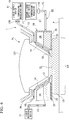
- FIG. 4 is a view for explaining the immersion mechanism and the temperature regulating mechanism.
- FIG. 5A is a view for explaining the operation of the temperature regulating mechanism.
- FIG. 5B is a view for explaining the operation of the temperature regulating mechanism.
- FIG. 6 is an enlarged view showing principal parts of an exposure apparatus according to a second embodiment.
- FIG. 7 is an enlarged view showing principal parts of an exposure apparatus according to a third embodiment.
- FIG. 8 is an enlarged view showing principal parts of an exposure apparatus according to a fourth embodiment.
- FIG. 9 is an enlarged view showing principal parts of an exposure apparatus according to a fifth embodiment.
- FIG. 10 is a view showing an exposure apparatus according to a sixth embodiment.
- FIG. 11 is a flow chart showing an example of manufacturing steps for a micro device.
- FIG. 1 is a schematic block diagram showing an exposure apparatus EX according to a first embodiment.
- the exposure apparatus EX includes a mask stage MST capable of holding and moving a mask M, a substrate stage ST 1 having a substrate holder PH holding a substrate P and capable of moving the substrate P held by the substrate holder PH, a measurement stage ST 2 capable of mounting and moving at least some of measuring devices which measure exposure treatment, an illumination optical system IL for illuminating the mask M held by the mask stage MST with exposure light EL, a projection optical system PL for projecting a pattern image of the mask M illuminated with the exposure light EL onto the substrate P held on the substrate stage ST 1 , and a control unit CONT for controlling operation of the whole exposure apparatus EX.
- the substrate stage ST 1 and the measurement stage ST 2 are adapted to be movable independently from each other on a base member BP, at adjacent a image plane side of the projection optical system PL.
- the exposure apparatus EX of the present embodiment is an immersion exposure apparatus, to which an immersion method is applied, for substantially shortening the exposure wavelength to improve the resolution, and also substantially expanding the depth of focus.
- This exposure apparatus includes an immersion mechanism 1 which fills an optical path space K 1 of exposure light EL on the image plane side of the projection optical system PL with a liquid LQ to form an immersion space.
- the immersion mechanism 1 includes a nozzle member 70 which is provided in the vicinity of the image plane of the projection optical system PL, and has a supply port 12 which supplies the liquid LQ to the optical path space K 1 and a recovery port 22 which recovers the liquid LQ in the optical path space K 1 , a liquid supply device 11 which supplies the liquid LQ to adjacent the image plane side of the projection optical system PL via a first supply pipe 13 and the supply port 12 provided in the nozzle member 70 , and a liquid recovery device 21 which recovers the liquid LQ at the image plane side of the projection optical system PL via the recovery port 22 provided in the nozzle member 70 , and a recovery pipe 23 .
- a passage (supply passage) 14 which connects the supply port 12 with the first supply pipe 13 , and a passage (recovery passage) 24 which connects the recovery port 22 with the recovery pipe 23 are provided inside the nozzle member 70 .
- the supply port, the recovery port, the supply passage, and the recovery passage are not shown in FIG. 1 .
- the nozzle member 70 is formed annularly so as to surround the front optical element LS 1 nearest to the image plane of the projection optical system PL, among a plurality of optical elements constituting the projection optical system PL.
- the exposure apparatus EX of the present embodiment adopts a local liquid immersion method in which an immersion region LR which is greater than the projection region AR and is smaller than the substrate P is locally formed with a liquid LQ on a portion area including a projection region AR of the projection optical system PL on the substrate P.
- the exposure apparatus EX fills the liquid LQ into the optical path space K 1 for the exposure light EL between the front optical element LS 1 nearest to the image plane of the projection optical system PL and the substrate P arranged at adjacent the image plane side of the projection optical system PL by using the immersion mechanism 1 , and irradiates the substrate P with the exposure light EL which has passed through the mask M via the projection optical system PL and the liquid LQ filled in the optical path space K 1 , thereby projecting and exposing the pattern image of the mask M onto the substrate P.
- the control unit CONT supplies a predetermined amount of the liquid LQ by using the liquid supply device 11 of the immersion mechanism 1 and recovers a predetermined amount of the liquid LQ by using the liquid recovery device 21 , thereby filling the optical path space K 1 with the liquid LQ, and locally forms the immersion region LR of the liquid LQ on the substrate P.
- the optical path space K 1 is filled with the liquid LQ in a state where the projection optical system PL and the substrate P face each other.
- the same is true in the case where the optical path space K 1 is filled with the liquid LQ in a state where an object (for example, at least a portion of the substrate stage ST 1 and the measurement stage ST 2 ) other than the substrate P faces the projection optical system PL.
- a scan type exposure apparatus which exposes a pattern formed on the mask M to the substrate P while the mask M and the substrate P are synchronously moved in a scanning direction is used as the exposure apparatus EX will be described as an example.
- a synchronous moving direction (scanning direction) of the mask M and the substrate P within a horizontal plane is defined as the X-axis direction
- a direction (a non-scanning direction) orthogonal to the X-axis direction in the horizontal plane is defined as the Y-axis direction
- a direction (in this example, a direction parallel to an optical axis AX of the projection optical system PL) orthogonal to both the X-axis direction and the Y-axis direction is defined as the Z axis direction.
- directions of rotation (inclination) about the X axis, the Y axis, and the Z axis are defined as the ⁇ X, the ⁇ Y, and the ⁇ Z directions, respectively.
- substrate includes a substrate which is obtained by coating a film, such as a resist and a protective film, on a semiconductor wafer.
- the “mask” includes a reticle in which a device pattern to be reduction-projected onto a substrate is formed.
- the exposure apparatus EX is equipped with a temperature regulating mechanism 60 for suppressing a change in the temperature of an immersion space forming member (the nozzle member 70 in the present embodiment) after the liquid LQ in the optical path space K 1 has been removed (namely, after formation of the immersion space has been deactivated).
- the temperature regulating mechanism 60 connects the liquid supply device 11 with the recovery passage 24 provided in the nozzle member 70 , and is equipped with a second supply pipe 15 which supplies the liquid LQ delivered from the liquid supply device 11 to the recovery passage 24 .
- the illumination optical system IL has a light source for exposure, an optical integrator which uniformizes the illuminance of a flux of light emitted from the light source for exposure, a condenser lens which condenses the exposure light EL from the optical integrator, a relay lens system, and a field stop which sets an illuminated region on the mask M of the exposure light EL.
- a predetermined illuminated region on the mask M is illuminated with the exposure light EL having uniform illuminance distribution by the illumination optical system IL.
- emission lines g-ray, h-ray, i-ray
- emission lines g-ray, h-ray, i-ray
- DUV beams deep ultraviolet beams
- ArF excimer laser beams wavelength: 193 nm
- F 2 laser beams wavelength: 157 nm
- the ArF excimer laser beams are used.
- pure water is used as the liquid LQ.
- emission lines g-ray, h-ray, i-ray
- KrF excimer laser beams wavelength: 248 nm
- the mask stage MST is capable of holding and moving the mask M.
- the mask stage MST holds the mask M, for example, by vacuum absorption, etc.
- the mask stage MST is movable two-dimensionally within a plane vertical to the optical axis AX of the projection optical system PL, i.e., within an XY plane, and is rotatable minutely in the ⁇ Z direction, in a state where it holds the mask M by driving of a mask stage drive MD including a linear motor controlled by the control unit CONT.
- a moving mirror 51 is provided on the mask stage MST.
- a laser interferometer 52 is provided in a position which faces the moving mirror 51 .
- the position in the two-dimensional directions and the rotation angle (in some cases, the rotation angles in the ⁇ X and ⁇ Y directions are also included) in the ⁇ Z direction are measured in real time by the laser interferometer 52 .
- the measurement results of the laser interferometer 52 are output to the control unit CONT.
- the control unit CONT controls the mask stage drive MD and controls the position of the mask M held by the mask stage MST, on the basis of the measurement results of the laser interferometer 52 .
- the laser interferometer 52 may be provided such that a portion (for example, optical system) thereof faces the moving mirror 51 .
- the moving mirror 51 may include not only a plane mirror, but also a corner cube (retroreflector). Otherwise, instead of securing the moving mirror 51 , for example, a reflecting surface which is formed by mirror-polishing the end surface (side surface) of the mask stage MST may be used.
- the mask stage MST may be of a construction capable of coarse/fine movement as disclosed for example in Japanese Unexamined Patent Application, First Publication No. H8-130179 (corresponding U.S. Pat. No. 6,721,034).
- the projection optical system PL is a system which projects a pattern of the mask M onto the substrate P at a predetermined projection magnification ⁇ , and is composed of a plurality of optical elements, and these optical elements are held by a lens barrel PK.
- the projection optical system PL is a reduction system with a projection magnification of for example 1 ⁇ 4, 1 ⁇ 5, or 1 ⁇ 8, and forms a reduced image of the mask pattern on the projection region AR conjugate with the aforementioned illuminated region.
- the projection optical system PL may be a reduction system, an equal system or a magnification system.
- the projection optical system PL may include any one of a refractive system which does not include a reflection optical element, a reflection system which does not include a refractive optical element, or a cata-dioptric system which includes a reflection optical element and a refractive optical element.
- the front optical element LS 1 is a lens element having refractive power, it may be a plane-parallel plate having no refractive power.
- the substrate stage ST 1 has a substrate holder PH for holding the substrate P, and is capable of moving the substrate P held on the substrate holder PH.
- the substrate holder PH holds the mask M, for example, by vacuum absorption, etc.
- a recess 58 is provided on the substrate stage ST 1 , and the substrate holder PH for holding the substrate P is arranged in the recess 58 .
- a top face 57 of the substrate stage ST 1 other than the recess 58 is formed as a flat face such that it has substantially the same height (flush with) as the surface of the substrate P held by the substrate holder PH.
- a portion of the aforementioned immersion region LR which runs out from the surface of the substrate P is formed on the top face 57 at the time of the exposure operation of the substrate P.
- Only a portion of the top face 57 of the substrate stage ST 1 for example, a predetermined region surrounding the substrate P (including the region where the immersion region LR runs out), may be approximately the same height as the surface of the substrate P.
- the optical path space K 1 on the image plane side of the projection optical system PL is continuously filled with the liquid LQ (that is, if the immersion region LR can be favorably maintained)
- the substrate holder PH may be formed integrally with a portion of the substrate stage 1 .
- the substrate holder PH and the substrate stage 1 are made separate, and the substrate holder PH is secured in the recess 58 , for example, by vacuum absorption.
- the substrate stage ST 1 is movable two-dimensionally within the XY plane on the base member BP, and is rotatable minutely in the ⁇ Z direction, in a state where it holds the substrate P with the substrate holder PH by driving of a substrate stage drive MD 1 including a linear motor controlled by the control unit CONT. Furthermore, the substrate stage ST 1 is also movable in the Z-axis direction, ⁇ X direction, and ⁇ Y direction. Accordingly, the surface of the substrate P held on the substrate stage ST 1 is movable in directions of six degrees of freedom, i.e., in the X-axis, Y-axis, Z-axis, ⁇ X, ⁇ Y, and ⁇ Z directions.
- a moving mirror 53 is provided on a side face of the substrate stage ST 1 . Furthermore, a laser interferometer 54 is provided in a position which faces the moving mirror 53 . As for the substrate P on the substrate stage ST 1 , the position in the two-dimensional directions and the rotation angle are measured in real time by the laser interferometer 54 . Furthermore, although not shown, the exposure apparatus EX is equipped with a focus leveling detecting system which detects surface positional information on the surface of the substrate P held on the substrate stage ST 1 .
- the laser interferometer 54 may be provided such that only a portion (for example, optical system) thereof faces the moving mirror 53 , and may measure the position in the Z-axis direction, and rotational information in the ⁇ X and ⁇ Y directions, of the substrate stage ST 1 .
- Details of an exposure apparatus having a laser interferometer which is capable of measuring the position in the Z axis direction of the substrate stage ST 1 are disclosed in, for example, Japanese Unexamined Patent Application, First Publication No. 2001-510577 (corresponding PCT International Publication No. WO 1999/28790).
- a reflecting surface which is formed by mirror-polishing a portion (the side face, etc.) of the substrate stage ST 1 may be used.
- the focus leveling detecting system is a system which measures the positional information in the Z-axis direction of the substrate P at a plurality of measuring points, respectively, thereby detecting the inclination information (rotation angle) in the ⁇ X and ⁇ Y directions of the substrate P.
- At least some of the plurality of measuring points may be set within the immersion region LR (or projection region AR), or all the measuring points may be set outside the immersion region LR.
- the laser interferometer 54 when the laser interferometer 54 is capable of measuring the positional information in the Z-axis, ⁇ X, and ⁇ Y directions of the substrate P, then it is possible to measure the positional information in the Z-axis direction during the exposure operation of the substrate P, and hence the focus leveling detection system may not be provided, and position control of the substrate P in the Z-axis, ⁇ X, and ⁇ Y directions may be performed using the measurement results of the laser interferometer 54 , at least during the exposure operation.
- the measurement results of the laser interferometer 54 are output to the control unit CONT.
- the detection results of the focus leveling detecting system are also output to the control unit CONT.
- the control unit CONT drives the substrate stage drive SD 1 , and controls the focusing position (Z position) and inclination angle ( ⁇ X, ⁇ Y) of the substrate P.
- the surface of the substrate P is matched with an image plane formed via the projection optical system PL and liquid LQ, and position control in the X-axis direction, Y-axis direction, and ⁇ Z direction of the substrate P is performed on the basis of the measurement results of the laser interferometer 54 .
- the measurement stage ST 2 is mounted with various measuring devices (including a measuring member) which measure exposure treatment, and is provided so as to be movable on the base member BP on the side of the image plane of the projection optical system PL.
- the measurement stage ST 2 is driven by a measurement stage drive SD 2 .
- the measurement stage drive SD 2 is controlled by the control unit CONT.
- the control unit CONT is capable of independently moving the substrate stage ST 1 and the measurement stage ST 2 on the base member BP, using the stage drives SD 1 and SD 2 , respectively.
- the measurement stage drive SD 2 has a configuration equivalent to the substrate stage drive SD 1 , and the measurement stage ST 2 is movable in the X-axis, Y-axis, and Z-axis directions and in the ⁇ X, ⁇ Y, and ⁇ Z directions by the measurement stage drive SD 2 , similarly to the substrate stage ST 1 . Furthermore, a moving mirror 55 is provided on the side face of the measurement stage ST 2 , and a laser interferometer 56 is provided in the position which faces the moving mirror 55 . The position in the two-dimensional directions and rotation angle of the measurement stage ST 2 are measured in real time by the laser interferometer 56 , and the control unit CONT controls the position of the measurement stage ST 2 on the basis of the measurement results of the laser interferometer 56 .
- the laser interferometer 56 may be provided such that only a portion (for example, an optical system) thereof faces the moving mirror 55 , and may measure the position in the Z-axis direction, and rotation angle in the ⁇ X and ⁇ Y directions, of the measurement stage ST 2 . Furthermore, instead of securing the moving mirror 55 to the measurement stage ST 2 , for example, a reflecting surface which is formed by mirror-polishing a portion (the side face, etc.) of the measurement stage ST 2 may be used.
- a spatial image measuring sensor as disclosed in Japanese Unexamined Patent Application, First Publication Nos. 2002-14005 and 2002-198303 (corresponding to U.S. Patent Publication No. 2002/0041377A1)
- a radiant exposure sensor as disclosed in Japanese Unexamined Patent Application, First Publication No. H11-16816 (corresponding to U.S. Patent Publication No. 2002/0061469A1)
- a wave aberration measuring device as disclosed in, for example, PCT International Patent Publication No. WO 99/60361 (corresponding to U.S. Pat. No.
- the measurement stage ST 2 is a dedicated stage for measuring exposure treatment, and has a configuration which does not hold the substrate P, and the substrate stage ST 1 has a configuration which is not mounted with a measuring device which measures exposure treatment.
- an exposure apparatus equipped with such a measurement stage is disclosed in detail in, for example, Japanese Unexamined Patent Application, First Publication No. H11-135400 (corresponding PCT International Publication No. WO 1999/23692), Japanese Unexamined Patent Application, First Publication No. 2000-164504 (corresponding U.S. Pat. No. 6,897,963), etc. At least some of the above-mentioned measuring devices may be mounted to the substrate stage ST 1 .
- control unit CONT can control (adjust) the driving of at least one of the stages ST 1 and ST 2 in the Z-axis direction (and/or ⁇ X and ⁇ Y directions) so that the top face 57 of the substrate stage ST 1 and the top face 59 of the measurement stage ST 2 may be located in substantially the same position (height) in the Z-axis direction.
- the control unit CONT can move the substrate stage ST 1 and the measurement stage ST 2 together, for example, in the X-axis direction below the projection optical system PL, thereby moving the immersion region LR formed at the image plane side of the projection optical system PL between the top face 57 of the substrate stage ST 1 and the top face 59 of the measurement stage ST 2 .
- the top faces 57 and 59 of the substrate stage ST 1 and the measurement stage ST 2 are set to substantially the same height (Z position), and so driving of the stages is performed concurrently.
- FIG. 2 is a sectional view in the vicinity of the nozzle member 70 .
- the liquid supply device 11 of the immersion mechanism 1 is a device which supplies the liquid LQ for filling the optical path space K 1 on the light emission side of the front optical element LS 1 with the liquid LQ, and has a tank containing the liquid LQ, a booster pump, a temperature regulating unit which regulates the temperature of the liquid LQ to be supplied, a filter unit which removes foreign matters in the liquid LQ, etc.
- a temperature regulating unit 18 is shown as an example in the drawing.
- One end of the first supply pipe 13 is connected to the liquid supply device 11 , and the other end of the first supply pipe 13 is connected to the nozzle member 70 .
- the liquid supply operation of the liquid supply device 11 is controlled by the control unit CONT. Not all of the tank, booster pump, temperature regulating unit, filter unit, etc. of the liquid supply device 11 need to be provided in the exposure apparatus EX, and they may be substituted with facilities in a factory in which the exposure apparatus EX is installed.
- the liquid recovery device 21 of the immersion mechanism 1 is a device which recovers the liquid LQ filled in the optical path space K 1 on the light emission side of the front optical element LS 1 , and has a vacuum system, such as a vacuum pump, a gas-liquid separator which separates the liquid LQ to be recovered and gas, and a tank which contains the recovered liquid LQ.
- a vacuum system such as a vacuum pump, a gas-liquid separator which separates the liquid LQ to be recovered and gas
- a tank which contains the recovered liquid LQ.
- One end of the recovery pipe 23 is connected to the liquid recovery device 21 , and the other end of the recovery pipe 23 is connected to the nozzle member 70 .
- the liquid recovery operation of the liquid recovery device 21 is controlled by the control unit CONT. Not all of the vacuum system, gas-liquid separator, tank, etc. of the liquid recovery device 21 need to be provided in the exposure apparatus EX, and they may be substituted with facilities in a factory in which the exposure apparatus EX is installed.
- the nozzle member 70 is an annular member which is provided so as to surround at least one optical element (front optical element LS 1 in the present embodiment) which is arranged on the image plane side of the projection optical system PL, and has a hole 70 H in the center of which the front optical element LS 1 can be disposed.
- the nozzle member 70 has a bottom plate 71 which faces the surface of the substrate P held on the substrate stage ST 1 , an inclined plate 72 which faces a side face LT of the front optical element LS 1 , a side plate 73 , and a top plate 75 .
- the inclined plate 72 is formed in the shape of a pot, and the front optical element LS 1 is arranged inside the hole 70 H formed by the inclined plate 72 .
- the side face LT of the front optical element LS 1 and an internal surface 70 T of the hole 70 H of the nozzle member 70 face each other with a predetermined gap.
- the bottom plate 71 is arranged between the bottom face of the front optical element LS 1 , and the substrate P.
- An opening 74 for allowing the exposure light EL to pass therethrough is provided in the bottom plate 71 .
- a top face 71 A of the bottom plate 71 faces the bottom face of the front optical element LS 1 with a predetermined gap
- a bottom face 71 B of the bottom plate 71 faces the surface of the substrate P with a predetermined gap.
- the top face 71 A of the bottom plate 71 is connected with a bottom end of the internal surface 70 T.
- a bottom face 71 B of the bottom plate 71 is a flat face.
- the nozzle member 70 is equipped with the supply port 12 , which supplies the liquid LQ to the optical path space K 1 for the exposure light EL, and the recovery port 22 , which recovers the liquid LQ in the optical path space K 1 for the exposure light EL. Furthermore, the nozzle member 70 is equipped with the supply passage 14 connected to the supply port 12 , and the recovery passage 24 connected to the recovery port 22 .
- the supply port 12 is a port for supplying the liquid LQ to the optical path space K 1 , and is provided in the vicinity of the top face 71 A of the bottom plate 71 in the internal surface 70 T of the nozzle member 70 .
- the supply port 12 is provided outside the optical path space K 1 .
- a pair of the supply ports 12 is provided on both sides of the optical path space K 1 , respectively, in the X-axis direction.
- a pair of the supply ports 12 may be provided on both sides of the optical path space K 1 , respectively, in the Y-axis direction, and a plurality of the supply ports may be provided so as to surround the optical path space K 1 .
- the supply passage 14 is formed by a through hole in the shape of a slit which penetrates the inclined plate 72 of the nozzle member 70 in a direction of inclination.
- the supply port 12 and the first supply pipe 13 are connected together via the supply passage 14 .
- the other end of the first supply pipe 13 is connected with a top end of the supply passage 14
- the supply port 12 is connected with a bottom end of the supply passage 14 . Accordingly, the liquid supply device 11 and the supply port 12 are connected together via the first supply pipe 13 and the supply passage 14 , and the liquid LQ is supplied to the supply port 12 from the liquid supply device 11 .
- the liquid LQ supplied from the supply port 12 is filled into a predetermined space K 2 between the bottom faces of the projection optical system PL and nozzle member 70 and the surface of the substrate P (immersion space), including the optical path space K 1 .
- the liquid LQ is held between the projection optical system PL and the nozzle member 70 , and the substrate P.
- the liquid LQ filled into the predetermined space K 2 contacts at least a portion of the nozzle member 70 .
- valve mechanism 13 B which can open and close the passage of the first supply pipe 13 is provided in the middle of the passage of the first supply pipe 13 .
- the operation of the valve mechanism 13 B is controlled by the control unit CONT.
- the control unit CONT can operate the valve mechanism 13 B so as to close the passage of the first supply pipe 13 , thereby stopping supply of the liquid LQ to the supply port 12 from the liquid supply device 11 .
- the recovery port 22 is a port for recovering the liquid LQ in the optical path space K 1 , and is provided in the bottom face of the nozzle member 70 facing the substrate P.
- the recovery port 22 is provided annularly so as to surround the optical path space K 1 further outside the supply port 12 and the bottom plate 71 with respect to the optical path space K 1 .
- the recovery passage 24 is provided inside the nozzle member 70 .
- a space which is open downward between the inclined plate 72 and the side plate 73 is formed in the nozzle member 70 , and the recovery passage 24 is constituted by this space.
- the recovery port 22 is arranged in a lower end (opening) of the space, and is connected to the recovery passage 24 .
- the other end of the recovery pipe 23 is connected to a portion of the recovery passage 24 . Accordingly, the liquid recovery device 21 and the recovery port 22 are connected together via the recovery passage 24 and the recovery pipe 23 .
- the liquid recovery device 21 including a vacuum system can form a negative pressure in the recovery passage 24 , thereby recovering the liquid LQ which exists in the predetermined space K 2 between the substrate P and the nozzle member 70 and projection optical system PL via the recovery port 22 , including the optical path space K 1 .
- the liquid LQ filled into the optical path space K 1 (predetermined space K 2 ) flows into the recovery passage 24 via the recovery port 22 of the nozzle member 70 , and the liquid LQ which has flowed into the recovery passage 24 is recovered by the liquid recovery device 21 .
- the liquid recovery device 21 can form a negative pressure in the recovery passage 24 , thereby recovering the liquid LQ in the optical path space K 1 (predetermined space K 2 ) via the recovery port 22 and recovering the liquid LQ of the recovery passage 24 .
- the nozzle member 70 is equipped with a porous member 25 , which has a plurality of holes provided so as to cover the recovery port 22 .
- the porous member 25 is formed annularly in plan view.
- the porous member 25 could be a porous body, etc. made from ceramic, it can be constituted by, for example, a mesh member with a plurality of holes.
- titanium, stainless steel (for example, SUS316), ceramics, etc. can be exemplified.
- the porous member 25 is formed from titanium and has lyophilicity (hydrophilic properties) to the liquid LQ.
- the porous member 25 may be formed from lyophilic materials other than titanium.
- the porous member 25 may be formed from stainless steel (for example, SUS316), and may be subjected to lyophilic treatment (surface treatment) so that the surface thereof may be made lyophilic.
- lyophilic treatment treatment which causes chrome oxide to adhere to the porous member 25 can be exemplified.
- “GOLDEP” treatment or “GOLDEP WHITE” treatment with Kobelco Eco-Solutions Co., Ltd. can be exemplified.
- elution of impurities from the porous member 25 to the liquid LQ is suppressed by performing such surface treatment.
- the porous member 25 has a bottom face 26 which faces the substrate P held on the substrate stage ST 1 .
- the bottom face 26 of the porous member 25 is substantially flat.
- the porous member 25 is provided in the recovery port 22 so that the bottom face 26 thereof may be substantially parallel to the surface (namely, XY plane) of the substrate P held on the substrate stage ST 1 .
- the bottom face 26 of the porous member 25 provided in the recovery port 22 and the bottom face 71 B of the bottom plate 71 are provided in substantially the same position (height) from the surface of the substrate P.
- FIG. 3A is a partially enlarged sectional view of the porous member 25 , and is a schematic diagram for explaining the liquid recovery operation performed via the porous member 25 .
- the immersion mechanism 1 is provided so as to recover only the liquid LQ via the recovery port 22 . Accordingly, the immersion mechanism 1 can recover the liquid LQ well, without causing gas to substantially flow into the recovery passage 24 via the recovery port 22 .
- the porous member 25 is provided in the recovery port 22 . Furthermore, the substrate P is arranged below the porous member 25 . Furthermore, in FIGS. 3A and 3B , a gas space and a liquid space are formed between the porous member 25 and the substrate P. More specifically, a gas space is formed between a first hole 25 Ha of the porous member 25 and the substrate P, and a liquid space is formed between a second hole 25 Hb of the porous member 25 and the substrate P. Furthermore, the recovery passage (passage space) 24 is formed above in the porous member 25 .
- the pressure (pressure on the bottom face of the porous member 25 H) between the first hole 25 Ha of the porous member 25 and the substrate P is defined as “Pa”
- the pressure (pressure on the top face the porous member 25 ) of the passage space 24 above the porous member 25 is defined as “Pc”
- the hole diameter (diameter) of each of the holes 25 Ha and 25 Hb is defined as “d”
- the angle of contact of the porous member 25 (internal surface of the hole 25 H) with respect to the liquid LQ is defined as “ ⁇ ”
- the surface tension of the liquid LQ is defined as “ ⁇ ”
- the immersion mechanism 1 of the present embodiment is set to satisfy the following condition: (4 ⁇ cos ⁇ )/ d ⁇ ( Pa ⁇ Pc ) (1)
- the hydrostatic pressure of the liquid LQ above the porous member 25 is not taken into consideration.
- an interface between the liquid LQ and the gas can be maintained inside the first hole 25 Ha of the porous member 25 , and thus the gas can be prevented from entering the passage space 24 from the gas space under the porous member 25 via the first hole 25 Ha, by optimizing the hole diameter “d” of the porous member 25 , the contact angle (affinity) ⁇ of the porous member 25 with respect to the liquid LQ, the surface tension “ ⁇ ” of the liquid LQ, and the pressures Pa and Pc so as to satisfy the above conditions. Meanwhile, since the liquid space is formed below the second hole 25 Hb of the porous member 25 (on the side of the substrate P), only the liquid LQ can be recovered via the second hole 25 Hb of the porous member 25 .
- the immersion mechanism 1 controls the suction power of the liquid recovery device 21 to regulate the pressure Pc of the passage space 24 above the porous member 25 so as to satisfy the above conditions.
- the hole diameter d be made as small as possible, and the contact angle ⁇ of the porous member 25 with respect to the liquid LQ be made as small as possible.
- the porous member 25 has lyophilicity to the liquid LQ, and has a sufficiently small contact angle ⁇ .
- each hole formed in the porous member 25 is formed so that the aperture diameter on the side of the top face and the aperture diameter on the side of the bottom face in the porous member 25 may become substantially the same.
- the aperture diameter on the side of the top face of each hole of the porous member 25 may be made different from the aperture diameter on the side of the bottom face.
- experiments show that, if the aperture diameter on the side of the top face of each hole of the porous member 25 is made smaller than the aperture diameter on the side of the bottom face as shown in FIG. 3B , the absolute value of the above-mentioned (Pa ⁇ Pc) can be made greater.
- the liquid LQ in the passage space 24 moves into the space below the porous member 25 by performing control so as to satisfy the above conditions. That is, if the above conditions are satisfied, the liquid LQ in the passage space (recovery passage) 24 , that is, a space above the porous member 25 , will not drip into the space below the porous member 25 via the porous member 25 .
- the gas space is formed in a portion of the passage space 24 , it is more desirable to fill the whole passage space 24 with the liquid LQ.
- the temperature regulating mechanism 60 is a mechanism for suppressing a change in the temperature of the nozzle member 70 after the liquid LQ in the optical path space K 1 has been removed.
- the liquid LQ is held between the projection optical system PL and nozzle member 70 , and the substrate P, and thereby the liquid LQ is filled into the predetermined space K 2 including the optical path space K 1 .
- the liquid LQ in the predetermined space K 2 including the optical path space K 1 has been removed (after formation of an immersion space has been deactivated)
- at least a portion of the liquid LQ in contact with the nozzle member 70 may evaporate.
- the nozzle member 70 may change (drop) in temperature due to the heat of evaporation generated by evaporation of the liquid LQ.
- the temperature regulating mechanism 60 suppresses a drop in the temperature of the nozzle member 70 caused by the heat of evaporation generated by evaporation of at least a portion of the liquid LQ in contact with the nozzle member 70 after the liquid LQ in the predetermined space K 2 including the optical path space K 1 has been removed.
- the temperature regulating mechanism 60 is connected to the liquid supply device 11 and the recovery passage 24 provided in the nozzle member 70 , and is equipped with the second supply pipe 15 which supplies the liquid LQ delivered from the liquid supply device 11 to the recovery passage 24 . That is, the liquid supply device 11 can supply the liquid LQ to the recovery passage 24 via the second supply pipe 15 .
- the temperature regulating mechanism 60 supplies the liquid LQ for regulating the temperature of the nozzle member 70 to the recovery passage 24 via the second supply pipe 15 from the liquid supply device 11 .
- liquid LQ which is delivered from the liquid supply device 11 and supplied to the optical path space K 1 from the supply port 12 and the liquid LQ which is delivered from the liquid supply device 11 and supplied to the recovery passage 24 from the second supply pipe 15 for regulating the temperature of the nozzle member 70 are the same liquids (pure water).
- the temperature regulating mechanism 60 is equipped with a flow rate controller 16 called a mass flow controller, which is provided in the middle of the second supply pipe 15 to control the amount per unit time of liquid LQ supplied to the recovery passage 24 from the liquid supply device 11 .
- the operation of the flow rate controller 16 is controlled by the control unit CONT.
- the temperature regulating mechanism 60 is equipped with a temperature regulator 17 which is provided in the middle of the second supply pipe 15 , and is capable of regulating the temperature of the liquid LQ supplied to the recovery passage 24 from the liquid supply device 11 .
- the operation of the temperature regulator 17 is controlled by the control unit CONT.
- the temperature regulator 17 is a temperature regulator which is separate from the temperature regulating unit 18 provided in the liquid supply device 11 , and the control unit CONT can independently control the operation of the temperature regulator 17 and the operation of the temperature regulating unit 18 .
- the temperature regulator 17 is arranged between the liquid supply device 11 including the temperature regulating unit 18 and the nozzle member 70 , and can further regulate the temperature of the liquid LQ supplied via the temperature regulating unit 18 from the liquid supply device 11 .
- the control unit CONT drives the liquid supply device 11 to supply a predetermined amount of liquid LQ per unit time to the predetermined space K 2 including the optical path space K 1 from the supply port 12 , and drives the liquid recovery device 21 of the immersion mechanism 1 to recover a predetermined amount of liquid LQ per unit time via the recovery port 22 from the predetermined space K 2 including the optical path space K 1 , thereby filling the predetermined space K 2 including the optical path space K 1 with the liquid LQ to locally form the immersion region LR of the liquid LQ.
- the liquid LQ delivered from the liquid supply device 11 under the control of the control unit CONT flows through the first supply pipe 13 , the liquid is supplied to the space between the front optical element LS 1 of the projection optical system PL, and the bottom plate 71 via the supply passage 14 of the nozzle member 70 from the supply port 12 .
- the liquid LQ supplied from the supply port 12 reaches the opening 74 after it flows on the top face 71 A of the bottom plate 71 .
- the liquid LQ flows into the predetermined space K 2 between the nozzle member 70 and the substrate P via the opening 74 , and then the liquid LQ is filled into the predetermined space K 2 including the optical path space K 1 for the exposure light EL.
- the immersion mechanism 1 supplies the liquid LQ to the space between the front optical element LS 1 and the bottom plate 71 from the supply port 12 , thereby filling the optical path space K 1 for the exposure light EL between the front optical element LS 1 and the substrate P with the liquid LQ.
- the liquid recovery device 21 including a vacuum system driven under the control of the control unit CONT forms a negative pressure in the recovery passage 24 , thereby recovering the liquid LQ which exists in the predetermined space K 2 including the optical path space K 1 via the recovery port 22 in which the porous member 25 is arranged. After the liquid LQ in the predetermined space K 2 flows into the recovery passage 24 via the recovery port 22 of the nozzle member 70 and flows through the recovery pipe 23 , the liquid is recovered by the liquid recovery device 21 .
- the liquid recovery device 21 regulates the pressure (pressure (negative pressure) on the top face of the porous member 25 ) of the passage space 24 by using a pressure regulating mechanism (not shown), thereby recovering only the liquid LQ via the porous member 25 from the recovery port 22 .
- the control unit CONT projects and exposes the pattern image of the mask M onto the substrate P via the projection optical system PL and the liquid LQ in the optical path space K 1 while the projection optical system PL and the substrate P are moved relative to each other, in a state in which the optical path space K 1 for the exposure light EL is filled with the liquid LQ.
- the control unit CONT controls the mask stage MST and the substrate stage ST 1 to irradiate the substrate P with the exposure light EL while moving the mask M and the substrate P in the Y-axis direction, respectively, thereby exposing the substrate P.
- the liquid LQ is held between the nozzle member 70 and the substrate P to fill the optical path space K 1 .
- the immersion region LR of the liquid LQ is formed on the measurement stage ST 2 before or after exposure of the substrate P, and the control unit CONT measures exposure treatment if needed by using a measuring device mounted to the measurement stage ST 2 .
- the immersion region LR is movable between the top face 57 of the substrate stage ST 1 and the top face 59 of the measurement stage ST 2 .
- the measurement stage ST 2 is caused to face the bottom face of the front optical element LS 1 of the projection optical system PL during replacement of the substrate stage ST 1 , so that the optical path space K 1 can continue to be filled with the liquid LQ by using the immersion mechanism 1 .
- the measurement stage ST 2 when the measurement stage ST 2 has faced the front optical element LS 1 , a predetermined measurement operation is performed if needed, using a measuring device and/or a measuring member (for example, a reference mark, etc.), which is mounted to the measurement stage ST 2 . Furthermore, when the substrate stage ST 1 is arranged in the position which faces the front optical element LS 1 , for example, for the exposure operation of the substrate P, the measurement stage ST 2 is moved to a predetermined position (retreating position) away from the front optical element LS 1 .
- a measuring device and/or a measuring member for example, a reference mark, etc.
- At least one of the substrate stage ST 1 and the measurement stage ST 2 is arranged under the projection optical system PL, so that the optical path space K 1 can continue to be filled with the liquid LQ (that is, the immersion space (immersion region LR) can be maintained (held) on the light emission side of the front optical element LS 1 ).
- a predetermined amount F 1 of liquid LQ per unit time is supplied to the predetermined space K 2 including the optical path space K 1 from the supply port 12 .
- the amount of liquid per unit time supplied to the optical path space K 1 (predetermined space K 2 ) from the supply port 12 is appropriately called “first amount F 1 .”
- the immersion mechanism 1 recovers the liquid LQ which exists in the optical path space K 1 (predetermined space K 2 ) via the recovery port 22 at a predetermined amount per unit time.
- the immersion mechanism 1 makes the supply amount (first amount F 1 ) per unit time of liquid supplied to the optical path space K 1 (predetermined space K 2 ) from the supply port 12 substantially equal to the recovery amount of liquid per unit time to be recovered from the optical path space K 1 (predetermined space K 2 ) via the recovery port 22 . That is, the amount of the liquid LQ which flows into the recovery passage 24 via the recovery port 22 from the predetermined space K 2 is substantially equal to the first amount F 1 .
- the optical path space K 1 is filled with the liquid LQ while the supply amount of liquid to the optical path space K 1 and the recovery amount of liquid from the optical path space K 1 are balanced, and occurrence of drawbacks, such as enlargement of the immersion region LR, leakage of the liquid LQ, or depletion (liquid run-out) of the liquid LQ is prevented.
- control unit CONT continues supplying a predetermined amount F 2 of liquid LQ per unit time to the recovery passage 24 via the second supply pipe 15 from the liquid supply device 11 , while the optical path space K 1 of the exposure light EL is filled with the liquid LQ, as shown in FIG. 5A . That is, the control unit CONT continues supplying the liquid LQ to the recovery passage 24 from the liquid supply device 11 via the second supply pipe 15 , which constitutes the temperature regulating mechanism 60 , even while the substrate P is immersion-exposed.
- second amount F 2 the supply amount per unit time of liquid supplied from the second supply pipe 15 (temperature regulating mechanism 60 ) to the recovery passage 24 (nozzle member 70 ) in a state where the optical path space K 1 is filled with the liquid LQ.
- the liquid LQ with the amount of the sum (F 1 +F 2 ) of the first amount F 1 and the second amount F 2 will flow into the recovery passage 24 .
- the liquid recovery device 21 forms a negative pressure in the recovery passage 24 with a suction power W 1 according to the amount (F 1 +F 2 ) of the liquid LQ which flows into the recovery passage 24 , thereby making the liquid LQ in the predetermined space K 2 flow into the recovery passage 24 via the recovery port 22 to recover the liquid, and recovering the liquid LQ which has flowed into the recovery passage 24 from the second supply pipe 15 .
- the temperature of the liquid LQ supplied from the supply port 12 to the optical path space K 1 (predetermined space K 2 ), and the temperature of the liquid LQ supplied to the recovery passage 24 via the second supply pipe 15 may be set to different values. However, in the present embodiment, the above temperatures are regulated to almost the same value.
- the control unit CONT controls the valve mechanism 13 B to close the passage of the first supply pipe 13 , thereby stopping supply of the liquid LQ to the optical path space K 1 from the supply port 12 .
- the control unit CONT continues driving of the liquid recovery device 21 . Since the negative pressure of the recovery passage 24 is maintained by continuing driving of the liquid recovery device 21 , the liquid LQ in the predetermined space K 2 including the optical path space K 1 is recovered via the recovery port 22 , and then the optical path space K 1 (predetermined space K 2 ) will be in a state where the liquid LQ has been recovered fully.
- FIG. 4 is a view showing a state after the liquid LQ in the predetermined space K 2 including the optical path space K 1 has been recovered fully.
- the control unit CONT continues supplying the liquid LQ to the recovery passage 24 (nozzle member 70 ) via the second supply pipe 15 from the liquid supply device 11 even in a state where the liquid LQ in the optical path space K 1 is recovered fully, and thus there is no liquid LQ in the optical path space K 1 (predetermined space K 2 ). That is, in the present embodiment, the liquid LQ always continue to be supplied to the recovery passage 24 (nozzle member 70 ) via the second supply pipe 15 from the liquid supply device 11 .
- the temperature of the nozzle member 70 is regulated by the liquid LQ.
- the temperature of the nozzle member 70 may fall due to the heat of evaporation generated by evaporation of the liquid LQ in contact with the nozzle member 70 . If the bottom face of the nozzle member 70 , the porous member 25 , etc. are lyophilic, there is a high possibility that the liquid LQ will remain on the nozzle member 70 .
- various members for example, the front optical element LS 1 , which are arranged in the vicinity of the nozzle member 70 , may be cooled down, and consequently desired imaging characteristics may not be longer obtained.
- peripheral devices and members may be affected such that the environment (temperature) where the exposure apparatus EX is placed may change, or the measurement precision of an optical measuring device, such as a laser interferometer, may deteriorate, or a supporting member (a body of the exposure apparatus EX) which supports the projection optical system PL may be deformed thermally.
- the control unit CONT continues supplying the liquid LQ to the recovery passage 24 of the nozzle member 70 via the second supply pipe 15 of the temperature regulating mechanism 60 even while there is no liquid LQ in the optical path space K 1 , thereby controlling a temperature change (drop) in the nozzle member 70 .
- the negative pressure of the recovery passage 24 is maintained by the liquid recovery device 21 so as to satisfy the above Expression (1).
- the liquid LQ supplied to the recovery passage 24 via the second supply pipe 15 from the liquid supply device 11 is recovered by the liquid recovery device 21 without dripping from the porous member 25 to the lower predetermined space K 2 .
- the temperature change (temperature drop) of the nozzle member 70 can be suppressed.
- the control unit CONT makes the amount F 3 per unit time of the liquid LQ supplied to the recovery passage 24 from the liquid supply device 11 after the liquid LQ has been removed from the optical path space K 1 greater than the amount F 2 (second amount) per unit time of the liquid LQ supplied to the recovery passage 24 from the liquid supply device 11 during exposure of the substrate P, etc.
- the supply amount per unit time of liquid supplied to the recovery passage 24 (nozzle member 70 ) from the second supply pipe 15 (temperature regulating mechanism 60 ) in a state where there is no liquid LQ in the optical path space K 1 is appropriately called “third amount F 3 .”
- the suction power W 1 of the liquid recovery device 21 is not changed greatly in a state where there exists or is no liquid LQ in the optical path space K 1 , the liquid recovery device 21 can maintain the negative pressure state of the recovery passage 24 so as to satisfy the above Expression (1).
- the control unit CONT drives the valve mechanism 13 B to open the passage of the first supply pipe 13 , thereby starting supply of the liquid LQ to the optical path space K 1 from the supply port 12 .
- the liquid LQ is supplied to the optical path space K 1 from the supply port 12 by the first amount F 1 .
- the control unit CONT controls the flow rate controller 16 to supply the liquid LQ to the recovery passage 24 via the second supply pipe 15 by the second amount F 2 .
- the temperature regulating mechanism 60 for suppressing a change in the temperature of the nozzle member 70 since the temperature regulating mechanism 60 continues supplying the liquid LQ to the recovery passage 24 of the nozzle member 70 in order to regulate the temperature of the nozzle member 70 even in a state where there is no liquid LQ in the optical path space K 1 after the liquid LQ in the optical path space K 1 has been removed, it is possible to suppress a drop in the temperature of the nozzle member 70 caused by the heat of evaporation of the liquid LQ after the liquid LQ in the optical path space K 1 has been removed.
- a great change in the temperature of the nozzle member 70 can be suppressed by making the temperature of the liquid LQ supplied to the recovery passage 24 via the second supply pipe 15 from the liquid supply device 11 in order to regulate the temperature of the nozzle member 70 in a state where there is no liquid LQ in the optical path space K 1 substantially equal to the temperature of the liquid LQ supplied to the optical path space K 1 via the supply port 12 when the substrate P is exposed. Furthermore, the regulated amount (controlled amount) of the temperature regulating unit 18 will be changed when the temperature of the liquid LQ to be supplied is changed.
- the operation rate of the exposure apparatus EX can be improved. That is, there is a possibility that it may be necessary to provide a latency time until the states (temperature, cleanness, etc.) of the liquid LQ to be delivered from the liquid supply device 11 are stabilized when the operation of the liquid supply device 11 is stopped once and then the operation is resumed.
- the liquid supply device 11 it is not necessary to provide the above-described latency time, for example, even when the operation which supplies the liquid LQ to the optical path space K 1 with no liquid LQ is resumed.
- the liquid LQ whose temperature has been regulated by the temperature regulating unit 18 or the temperature regulator 17 will be supplied to the nozzle member 70 in a large amount when there is no liquid LQ in the optical path space K 1 by making the third amount F 3 of the liquid LQ supplied to the recovery passage 24 from the liquid supply device 11 after the liquid LQ is removed from the optical path space K 1 greater than the second amount F 2 of the liquid LQ supplied to the recovery passage 24 from the liquid supply device 11 during exposure of the substrate P, a change in the temperature of the nozzle member 70 can be suppressed effectively.
- the third amount F 3 of the liquid LQ supplied to the recovery passage 24 from the liquid supply device 11 after the liquid LQ is removed from the optical path space K 1 is made substantially equal to the sum of the first amount F 1 of the liquid LQ supplied to the recovery passage 24 from the liquid supply device 11 during exposure of the substrate P, and the second amount F 2 of the liquid LQ supplied to the optical path space K 1 from the supply port 12 , it is not necessary to change the suction power W 1 of the liquid recovery device 21 greatly before and after the liquid LQ in the optical path space K 1 is removed.
- the suction power W 1 of the liquid recovery device 21 is changed, there is a possibility that a drawback may occur in that it is necessary to provide a latency time until the operation of the liquid recovery device 21 is stabilized.
- a decline in the operation rate of the exposure apparatus EX can be suppressed.
- the third amount F 3 is substantially equal to the sum of the first amount F 1 and the second amount FIG. 2 .
- the amount of supply of the liquid LQ is not limited thereto.
- the liquid LQ may be supplied to the optical path space K 1 from the supply port 12 by the first amount F 1 in order to fill the optical path space K 1 with the liquid LQ.
- the second amount F 2 of the liquid LQ supplied to the recovery passage 24 via the second supply pipe 15 from the liquid supply device 11 may be made substantially equal to the first amount F 1 .
- the amount of the liquid LQ which flows into the recovery passage 24 can be made to become the first amount F 1 even in a state where there is no or there exists liquid LQ in the optical path space K 1 .
- the first amount F 1 when the liquid LQ is supplied to the optical path space K 1 from the supply port 12 should be regulated depending on substrate conditions including a movement condition including the traveling speed of the substrate P when the substrate P is exposed, a contact angle condition of a film forming the surface of the substrate P with respect to the liquid LQ, etc. If the first amount F 1 is small, in order not to change the recovery power (suction power) W 1 of the liquid recovery device 21 after the liquid LQ is removed from the optical path space K 1 , it is necessary to reduce the third amount F 3 of the liquid LQ supplied to the recovery passage 24 according to the first amount F 1 for regulating the temperature of the nozzle member 70 .
- the liquid LQ continues to be supplied to the recovery passage 24 from the liquid supply device 11 for regulating the temperature of the nozzle member 70 even when the liquid LQ exists in the optical path space K 1 .
- the third amount F 3 can be made sufficiently large with the recovery power W 1 of the liquid recovery device 21 kept substantially constant by increasing the second amount F 2 .
- the amounts of supply (F 1 to F 3 ) of the liquid LQ are regulated without greatly changing the suction power W 1 of the liquid recovery device 21 so as to satisfy the above-mentioned Expression (1).
- the suction power W 1 of the liquid recovery device 21 may be regulated, or both the suction power W 1 of the liquid recovery device 21 and the amounts of supply (F 1 to F 3 ) of the liquid LQ may be regulated.
- the liquid LQ supplied to the optical path space K 1 from the supply port 12 and the liquid LQ supplied to the recovery passage 24 from the second supply pipe 15 are delivered from the same liquid supply device 11 . Therefore, when the liquid LQ is supplied from the supply port 12 , even if the temperature regulator 17 provided in the second supply pipe 15 is not necessarily driven, the temperature of the liquid LQ supplied to the optical path space K 1 from the supply port 12 and the temperature of the liquid LQ supplied to the recovery passage 24 from the second supply pipe 15 can be made substantially equal to each other by the temperature regulating unit 18 .
- the temperature of the liquid LQ to be delivered from the liquid supply device 11 including the temperature regulating unit 18 and supplied to the recovery passage 24 of the nozzle member 70 may be further regulated by the temperature regulator 17 .
- the temperature regulator 17 may be omitted.
- the temperature regulating mechanism 60 may make the temperature of the liquid LQ supplied to the recovery passage 24 for regulating the temperature of the nozzle member 70 higher than the temperature of the liquid LQ supplied to the optical path space K 1 from the supply port 12 .
- the temperature of the nozzle member 70 falls significantly due to heat of evaporation, a change in the temperature of the nozzle member 70 can be further suppressed by supplying the liquid LQ with comparatively high temperature to the nozzle member 70 (recovery passage 24 ).
- the temperature of the liquid LQ supplied to the nozzle member 70 (recovery passage 24 ) via the second supply pipe 15 can be made high using the temperature regulator 17 without changing the controlled amount of the temperature regulating unit 18 . Also, when supply of the liquid LQ from the supply port 12 is resumed, the liquid LQ whose temperature has been regulated by the temperature regulating unit 18 can be immediately supplied to the optical path space K 1 .
- the liquid LQ supplied to the recovery passage 24 for regulating the temperature of the nozzle member 70 and the liquid LQ supplied to the optical path space K 1 from the supply port 12 may be different kinds of liquids.
- the liquid LQ supplied to the optical path space K 1 from the supply port 12 is pure water.
- a liquid with larger specific heat than pure water may be used as the liquid LQ supplied to the recovery passage 24 for regulating the temperature of the nozzle member 70 .
- the above-described first embodiment is configured such that the liquid supply device 11 supplies the liquid LQ to the optical path space K 1 via the supply port 12 and supplies the liquid LQ to the recovery passage 24 (space on the side of the top face of the porous member 25 ) via the second supply pipe 15 , and such that the immersion mechanism 1 and the temperature regulating mechanism 60 also serve as the liquid supply device 11 .
- a second liquid supply device 11 ′ which supplies the liquid LQ to the nozzle member 70 (recovery passage 24 ) in order to regulate the temperature of the nozzle member 70 may be provided independently from the liquid supply device 11 which supplies the liquid LQ for filling the optical path space K 1 .
- regulation of the temperature of the liquid LQ supplied to the optical path space K 1 from the liquid supply device 11 and regulation of the temperature of the liquid LQ supplied to the recovery passage 24 from the second liquid supply device 11 ′ may be performed independently.
- the second liquid supply device 11 ′ may make the temperature of the liquid LQ for regulating the temperature of the nozzle member 70 equal to the temperature of the liquid LQ supplied to the optical path space K 1 from the supply port 12 , and higher than the temperature of the liquid LQ supplied to the optical path space K 1 .
- the liquid LQ for temperature regulation is allowed to flow to the recovery passage 24 on the side of the top face of the recovery port 22 (porous member 25 ) at the bottom face of the nozzle member 70 that faces the substrate P.
- the nozzle member 70 has an internal passage 61 through which the liquid LQ for adjusting the temperature of the nozzle member 70 flows, separately from the supply passage 14 connected to the supply port 12 for supplying the liquid LQ to the optical path space K 1 and the recovery passage 24 connected to the recovery port 22 for recovering the liquid LQ in the optical path space K 1 .
- the internal passage 61 is provided inside the inclined plate 72 , the side plate 73 , and the top plate 75 of the nozzle member 70 .
- the internal passage 61 may be formed annularly inside the nozzle member 70 and may be formed spirally so as to surround the optical path space K 1 , for example.
- An inlet connected to the second supply pipe 15 is provided in a portion of the internal passage 61 , and the liquid supply device 11 which constitutes the temperature regulating mechanism 60 supplies the liquid LQ to the internal passage 61 via the second supply pipe 15 and the inlet.
- an outlet for discharging the liquid LQ which has flowed through the internal passage 61 is provided at another portion of the internal passage 61 .
- the temperature regulating mechanism 60 can supply the liquid LQ from the inlet to the internal passage 61 and discharge the liquid LQ from the outlet, thereby continuing allowing the liquid LQ for temperature regulation to flow to the internal passage 61 .
- the control unit CONT supplies the liquid LQ to the internal passage 61 after the liquid LQ in the optical path space K 1 is removed. Furthermore, the control unit CONT supplies the liquid LQ to the internal passage 61 even in a state where the liquid LQ exists in the optical path space K 1 . Furthermore, the control unit CONT can regulate the temperature of the liquid LQ supplied to the internal passage 61 , using the temperature regulator 17 provided in the middle of the second supply pipe 15 . The control unit CONT makes the temperature of the liquid LQ supplied to the internal passage 61 substantially equal to the temperature of the liquid LQ supplied to the optical path space K 1 from the supply port 12 , using the temperature regulator 17 . A change in the temperature of the nozzle member 70 can be suppressed even by the configuration as described above.
- control unit CONT may supply the liquid LQ to the internal passage 61 after the liquid LQ in the optical path space K 1 is removed, and may stop supply of the liquid LQ to the internal passage 61 in a state where the liquid LQ exists in the optical path space K 1 .
- control unit CONT makes the temperature of the liquid LQ supplied to the internal passage 61 higher than the temperature of the liquid LQ supplied to the optical path space K 1 from the supply port 12 , using the temperature regulator 17 provided in the middle of the second supply pipe 15 .
- the liquid supply device which supplies the liquid LQ to the supply port 12 and the liquid supply device which supplies the liquid LQ to the internal passage 61 may be provided separately.
- the liquid LQ supplied to the optical path space K 1 from the supply port 12 and the liquid LQ supplied to the internal passage 61 may be different kinds of liquids. Furthermore, in order to regulate the temperature of the nozzle member 70 , gas may be supplied to the internal passage 61 .
- the temperature regulating mechanism 60 has a jacket member 62 which faces a wall surface of the nozzle member 70 , and through which the liquid LQ for regulating the temperature regulation of the nozzle member 70 flows.
- the jacket member 62 is a tubular member which has an internal passage, and is provided so as to be wound around the side plate 73 of the nozzle member 70 , and the jacket member 62 and the nozzle member 70 are in contact with each other.
- An inlet connected to the second supply pipe 15 is provided in a portion of the jacket member 62 , and an outlet for discharging the liquid LQ inside the jacket member 62 is provided in the other portion of the jacket member.
- the liquid supply device 11 supplies the liquid LQ to the jacket member 62 via the second supply pipe 15 and the inlet.
- the control unit CONT supplies the liquid LQ to the jacket member 62 after the liquid LQ in the optical path space K 1 is removed.
- control unit CONT always supplies the liquid LQ to the jacket member 62 even in a state where the liquid LQ exists in the optical path space K 1 . Furthermore, the control unit CONT can regulate the temperature of the liquid LQ supplied to the jacket member 62 , using the temperature regulator 17 provided in the middle of the second supply pipe 15 . The control unit CONT makes the temperature of the liquid LQ supplied to the jacket member 62 substantially equal to the temperature of the liquid LQ supplied to the optical path space K 1 from the supply port 12 , using the temperature regulator 17 . A change in the temperature of the nozzle member 70 can be suppressed even by the configuration as described above.
- control unit CONT may supply the liquid LQ to the jacket member 62 after the liquid LQ in the optical path space K 1 is removed, and may stop supply of the liquid LQ to the jacket member 62 in a state where the liquid LQ exists in the optical path space K 1 .
- control unit CONT makes the temperature of the liquid LQ supplied to the jacket member 62 higher than the temperature of the liquid LQ supplied to the optical path space K 1 from the supply port 12 , using the temperature regulator 17 provided in the middle of the second supply pipe 15 .
- the liquid supply device which supplies the liquid LQ to the supply port 12 and the liquid supply device which supplies the liquid LQ to the jacket member 62 may be provided separately.
- the liquid LQ supplied to the optical path space K 1 from the supply port 12 and the liquid LQ supplied to the jacket member 62 may be different kinds of liquids. Furthermore, in order to regulate the temperature of the nozzle member 70 , gas may be supplied to the jacket member 62 .
- the temperature regulating mechanism 60 has a heater 63 attached to the nozzle member 70 .
- the heater 63 is in contact with the side plate 73 of the nozzle member 70 .
- the control unit CONT suppresses a change in the temperature of the nozzle member 70 using the heater 63 after the liquid LQ in the optical path space K 1 is removed.
- the control unit CONT can suppress a drop in the temperature of the nozzle member 70 by warming the nozzle member 70 using the heater 63 .
- the control unit CONT can regulate the temperature of the nozzle member 70 using the heater 63 even in a state where the liquid LQ exists in the optical path space K 1 . A change in the temperature of the nozzle member 70 can be suppressed even by the configuration as described above.
- control unit CONT may regulate the temperature of the nozzle member 70 using the heater 63 after the liquid LQ in the optical path space K 1 is removed, and may not perform regulation of the temperature of the nozzle member 70 by the heater 63 in a state where the liquid LQ exists in the optical path space K 1 .
- the temperature regulating mechanism 60 has a radiating part 64 which radiates heat toward the nozzle member 70 .
- the radiating part 64 is provided in the measurement stage ST 2 .
- the radiating part 64 is provided on the top face 59 of the measurement stage ST 2 , which can face the nozzle member 70 .
- the radiating part 64 is constituted by, for example, a far-infrared ceramic heater, etc. Since the nozzle member 70 can be warmed by the heat radiated from the radiating part 64 by arranging the radiating part 64 in the position which faces the nozzle member 70 , even in a case where the temperature of the nozzle member 70 falls significantly due to the heat of evaporation generated by evaporation of the liquid LQ, a drop in the temperature of the nozzle member 70 can be suppressed by warming the nozzle member 70 using the radiating part 64 . A change in the temperature of the nozzle member 70 can be suppressed even by the configuration as described above.
- the radiating part 64 may be provided in the substrate stage ST 1 , or may be provided in a predetermined supporting mechanism (including a movable body, etc.) other than the substrate stage ST 1 and measurement stage ST 2 .
- the nozzle member 70 has both the supply port 12 and the recovery port 22 .
- the form of the nozzle member 70 is not limited to the above-described one.
- the temperature regulating mechanism in each of the above-described embodiments can be used when a change in the temperature of a nozzle member which has either a supply port or a recovery port can be suppressed.
- the immersion space forming member which fills the optical path space K 1 with the liquid LQ to form an immersion space (K 2 ) includes a portion of the immersion mechanism 1 , i.e., the nozzle member 70 .
- the immersion space forming member may include members other than the nozzle member 70 , and may have only either a supply port or a recovery port.
- formation of an immersion space is deactivated by removing the whole liquid LQ from the optical path space K 1 (full recovery).
- the present invention is not limited thereto.
- formation of an immersion space may be deactivated even when a portion of the liquid LQ in the optical path space K 1 (or predetermined space K 2 ) is removed so that the immersion region LR may be reduced compared with an immersion region at the time of exposure.
- formation of an immersion space may be deactivated.
- a change in the temperature of the immersion space forming member exceeds a predetermined allowable range by removing at least a portion of the liquid LQ, formation of an immersion space may be deactivated.
- the temperature regulating mechanisms 60 described in the above-described first to sixth embodiments may be used in appropriate combinations.
- the liquid LQ whose temperature has been regulated may be supplied to the recovery passage 24 of the nozzle member 70
- the internal passage 61 may be provided in the nozzle member 70 so that a fluid (liquid or gas) for temperature regulation may be caused to flow to the internal passage.
- the jacket member 62 as described in the fourth embodiment may be attached to the nozzle member 70
- the heater 63 as described in the fifth embodiment may be attached to the nozzle member.
- the nozzle member 70 may be warmed using the heat-radiating part 64 as described in the sixth embodiment.
- a temperature change resulting from evaporation of the liquid LQ which may occur in at least a portion of the nozzle member 70 can be reduced or prevented by temporarily releasing formation of the immersion space as mentioned above and by regulating the temperature of the nozzle member 70 like in the above-described first to sixth embodiments.
- a change in the temperature of the nozzle member 70 is suppressed by regulating the temperature of the nozzle member 70 .
- the temperature of at least the front optical element LS 1 of the projection optical system PL is changed due to the heat of evaporation of the liquid LQ with deactivation of formation of the immersion space.
- the temperature of the front optical element LS 1 may be regulated, for example, by supply of a temperature regulating fluid, irradiation of infrared rays, or temperature regulating elements (Peltier elements, etc.).
- the liquid LQ in each of the above embodiments is constituted by pure water.
- the pure water has advantages in that it can be easily obtained in large quantity in semiconductor manufacturing factories, etc. and in that it has no adverse effects on a photoresist and optical elements (lenses), etc. on the substrate P. Furthermore, since the pure water has no adverse effects on the environment and contains very low impurities, one can also expect effects such that the surface of the substrate P and the surface of an optical element provided at a tip face of the projection optical system PL are cleaned.
- an exposure apparatus may have an ultrapure water manufacturing machine.
- the refractive index n of the pure water (water) with respect to exposure light EL with a wavelength of about 193 nm is about 1.44. Therefore, when an ArF excimer laser beam (with a wavelength of 193 nm) is used as the light source of the exposure light EL, it is possible to shorten the wavelength to 1/n, that is, to about 134 nm on the substrate P, thereby obtaining high resolution. Moreover, the depth of focus is expanded by about n times, that is, about 1.44 times, compared with in air. Therefore, when it would be permissible to ensure the same level of depth of focus as the case where it is used in air, it is possible to further increase the numerical aperture of the projection optical system PL, and the resolution improves as well in terms of this point.
- the optical element LS 1 is attached to the tip of the projection optical system PL, and this lens can be used to adjust the optical properties, for example, aberrations (spherical aberration, coma aberration, etc.), of the projection optical system PL.
- An optical plate used for adjustment of the optical properties of the projection optical system PL may also be used as the optical element attached to the tip of the projection optical system PL.
- a plane parallel plate (cover glass or the like) through which the exposure light EL is able to pass may also be used as the optical element.
- the pressure between the substrate P and the optical element at the tip of the projection optical system PL generated by the flow of the liquid LQ is large, it is permissible to make the optical element not one that is replaceable but one that is firmly secured so that the optical element may not be moved by the pressure.
- the structure of the immersion mechanism 1 including the nozzle member 70 is not limited to the above-described structure.
- structures described in European Patent Publication No. 1420298, PCT International Publication No. WO 2004/055803, PCT International Publication No. WO. 2004/057590, and PCT International Publication No. WO. 2005/029559 can be used.
- the liquid LQ is filled between the projection optical system PL and the surface of the substrate P.
- the liquid LQ may be filled at least between the surface of the substrate and a cover glass composed of a plane parallel plate in a state where the cover glass is attached to the surface of the substrate P.
- the liquid LQ is filled between the projection optical system PL and the surface of the substrate P.
- the liquid LQ may be filled in a state where a cover glass composed of a plane-parallel plate is attached to the surface of the substrate P.
- the projection optical systems of the above-described embodiments are configured such that the optical path space on the side of the image plane of the optical element (LS 1 ) at the tip of each system is filled with the liquid.
- a projection optical system in which an optical path space on the side of an object plane of the optical element at the tip of the system is also filled with liquid can be adopted.
- a nozzle member for filling the optical path space on the side of the object plane with liquid is provided, a change in the temperature of the nozzle member may be suppressed.
- the liquid LQ of the above embodiments is water (pure water), it may be a liquid other than water.
- the light source of the exposure light EL is an F 2 laser
- this F 2 laser beam will not pass through water.
- the liquid LQ may be, for example, a fluorinated fluid, such as perfluoropolyether (PFPE) or fluorinated oil through which an F 2 laser beam is able to pass.
- PFPE perfluoropolyether
- lyophilic treatment is performed on a portion in contact with the liquid LQ, for example, by forming a thin film from a substance having a polar small molecular structure containing fluorine.
- liquids for example, cedar oil which have transmittance with respect to the exposure light EL, whose refractive index are as high as possible, and which are stable with respect to a photoresist coated on the projection optical system PL and the surface of the substrate P.
- the liquid LQ a liquid with a refractive index of about 1.6 to 1.8 may be used.
- the optical element LS 1 may be formed from quartz, or a material having a higher refractive index (for example, 1.6 or more) than quartz.
- various liquids for example, a supercritical liquid, can also be used.
- the immersion region LR may be formed by supplying a liquid LQ having substantially the same temperature as the temperature of the substrate P. As a result, thermal deformation, etc. of the substrate P caused by a temperature difference between the substrate and the liquid LQ can be prevented.
- positional information on each of the mask stage MST, the substrate stage ST 1 , and the measurement stage ST 2 is measured using an interferometer system ( 52 , 54 , 56 ).
- an encoder system which detects scales (diffraction grating) provided in each stage may be used.
- a hybrid system equipped with both the interferometer system and the encoder system is used, and calibration of measurement results of the encoder system is performed using measurement results of the interferometer system.
- positional control of the stage may be performed using the interferometer system and the encoder system interchangeably, or using both.
- the substrate P of the above embodiments not only a semiconductor wafer for manufacturing a semiconductor device, but also a glass substrate for a display device, a ceramic wafer for a thin-film magnetic head, an original plate (synthetic quartz or silicon wafer) of a mask or reticle, which is used for an exposure apparatus, etc., can be used.
- the present invention can be applied to a step-and-repeat type projection exposure apparatus (stepper) in which the pattern of the mask M is one-shot exposed in a state where the mask M and the substrate P are stationary, and the substrate P is sequentially moved stepwise, in addition to a scan-type exposure apparatus (scanning stepper) in which, while the mask M and the substrate P are moved synchronously, a pattern of the mask M is scan-exposed.
- stepper step-and-repeat type projection exposure apparatus in which the pattern of the mask M is one-shot exposed in a state where the mask M and the substrate P are stationary, and the substrate P is sequentially moved stepwise, in addition to a scan-type exposure apparatus (scanning stepper) in which, while the mask M and the substrate P are moved synchronously, a pattern of the mask M is scan-exposed.
- the present invention can also be applied to an exposure apparatus using a method in which a reduced image of a first pattern is one-shot exposed onto the substrate P by using a projection optical system (for example, a refractive projection optical system having a reduction magnification of 1 ⁇ 8, and having no reflecting element), in a state where the first pattern and the substrate P are substantially stationary.
- a projection optical system for example, a refractive projection optical system having a reduction magnification of 1 ⁇ 8, and having no reflecting element
- the present invention can also be applied to a stitch-type one-shot exposure apparatus in which, after the reduced image of the first pattern is one-shot exposed, a reduced image of a second pattern is one-shot exposed onto the substrate P by partially overlapping the first pattern and the second pattern using the projection optical system, in a state where the second pattern and the substrate P are substantially stationary.
- the present invention can also be applied to a step-and-stitch type exposure apparatus in which at least two patterns are transferred onto the substrate P in a partially overlapping manner, and the substrate
- the exposure apparatus equipped with the projection optical system PL is described as an example.
- the present invention can also be applied to an exposure apparatus and an exposure method which do not use such a projection optical system PL.
- exposure light can be radiated onto a substrate via an optical member such as a mask or lens, and an immersion region can be formed in a predetermined space between the optical element and the substrate.
- the present invention can also be applied to a twin-stage type exposure apparatus equipped with a plurality of substrate stages, as disclosed for example in Japanese Unexamined Patent Application, First Publication No. H10-163099, Japanese Unexamined Patent Application, First Publication No. H10-214783 (corresponding to U.S. Pat. No. 6,590,634), Published Japanese Translation No. 2000-505958 of the PCT International Publication (corresponding to U.S. Pat. No. 5,969,411), and U.S. Pat. No. 6,208,407.
- the present invention can also be applied to an exposure apparatus which is not equipped with a measurement stage, as disclosed in PCT International Publication No. WO 99/49504. Furthermore, the present invention can also be applied to an exposure apparatus equipped with a plurality of substrate stages and measurement stages.
- an exposure apparatus in which liquid is locally filled between the projection optical system PL and the substrate P is adopted.
- the present invention can also be applied to an immersion exposure apparatus in which exposure is performed in a state where the whole surface of a target exposure substrate is immersed in a liquid, as disclosed for example in Japanese Unexamined Patent Application, First Publication No. H06-124873, Japanese Unexamined Patent Application, First Publication No. H10-303114, and U.S. Pat. No. 5,825,043.
- the present invention is not limited to an exposure apparatus, for manufacturing semiconductor devices, which exposes a semiconductor device pattern onto a substrate P.
- the present invention can also be widely applied to exposure apparatuses for manufacturing liquid crystal display devices or for manufacturing displays, and exposure apparatuses for manufacturing thin-film magnetic heads, charge-coupled devices (CCD), micro machines, MEMS, DNA chips, reticles, masks, etc.
- CCD charge-coupled devices
- an optical transmission type mask in which a predetermined shielding pattern (or phase pattern or dimming pattern) is formed on a light-transmitting substrate is used.
- an electronic mask also called a variable form mask, and including, for example, a DMD (Digital Micro-mirror Device) as one type of non-light-emitting type image display device (spatial light modulator) for forming a transmitting pattern, reflecting pattern, or a light-emitting pattern, on the basis of electronic data of a pattern to be exposed
- DMD Digital Micro-mirror Device
- the present invention can also be applied to an exposure apparatus (lithography system) which forms interference fringes on a substrate P to expose a run-and-space pattern onto the substrate P, as disclosed for example in PCT International Publication No. WO 2001/035168.
- the present invention can also be applied to an exposure apparatus as disclosed, for example, in Published Japanese Patent Translation No. 2004-519850 (corresponding to U.S. Pat. No. 6,611,316), which synthesizes patterns of two masks on a substrate via a projection optical system, and double-exposes a one-shot region on the substrate at substantially the same time, by a single scan exposure.
- the exposure apparatuses EX of the embodiments of this application are manufactured by assembling various subsystems, including individual components as set forth in the claims of the present application so that predetermined mechanical precision, electrical precision, and optical precision can be maintained.
- adjustment for achieving optical precision with respect to various optical systems adjustment for achieving mechanical precision with respect to various mechanical systems, and adjustment for achieving electrical precision with respect to various electrical systems are performed before and after the above assembly.
- the process of assembly from the various subsystems to the exposure apparatus includes mechanical connection, electrical circuit wiring connection, pneumatic circuit piping connection, etc. among the various subsystems. It is obvious that there are processes of assembly of each of the subsystems before the process of assembly from these various subsystems to the exposure apparatus.
- micro devices such as semiconductor devices are manufactured through a step 201 of designing the function and performance of a micro device, a step 202 of fabricating a mask (reticle) on the basis of the designing step, a step 203 of manufacturing a substrate that is a device base material, a step 204 including substrate processing processes, such as a process of exposing a pattern on the mask onto a substrate by means of the exposure apparatus EX of the aforementioned embodiments, a process of developing the exposed substrate, and a process of heating (curing) and etching the developed substrate, a device assembly step 205 (including processing processes, such as a dicing process, a bonding process, and a packaging processing), and an inspection step 206 .
- substrate processing processes such as a process of exposing a pattern on the mask onto a substrate by means of the exposure apparatus EX of the aforementioned embodiments, a process of developing the exposed substrate, and a process of heating (curing) and etching the developed substrate
- a device assembly step 205 including
- a substrate can be effectively exposed by preventing deterioration of exposure precision resulting from a change in the temperature of an immersion space forming member.
- the present invention is very useful for an exposure apparatus and method for manufacturing a wide range of products, such as semiconductor devices, liquid crystal display devices or displays, thin-film magnetic heads, CCDs, micro machines, MEMS, DNA chips, and reticles (masks).
Abstract
Description
- [Patent Document 1] PCT International Publication No. WO 99/49504
(4×γ×cos θ)/d≧(Pa−Pc) (1)
In the above Expression (1), in order to simplify the description, the hydrostatic pressure of the liquid LQ above the
θ≦90 (2).
Claims (31)
Applications Claiming Priority (3)
| Application Number | Priority Date | Filing Date | Title |
|---|---|---|---|
| JP2005-120185 | 2005-04-18 | ||
| JP2005120185 | 2005-04-18 | ||
| PCT/JP2006/308040 WO2006112436A1 (en) | 2005-04-18 | 2006-04-17 | Exposure device, exposure method, and device manufacturing method |
Related Parent Applications (1)
| Application Number | Title | Priority Date | Filing Date |
|---|---|---|---|
| PCT/JP2006/308040 A-371-Of-International WO2006112436A1 (en) | 2005-04-18 | 2006-04-17 | Exposure device, exposure method, and device manufacturing method |
Related Child Applications (1)
| Application Number | Title | Priority Date | Filing Date |
|---|---|---|---|
| US13/299,891 Continuation US8724077B2 (en) | 2005-04-18 | 2011-11-18 | Exposure apparatus, exposure method, and device manufacturing method |
Publications (2)
| Publication Number | Publication Date |
|---|---|
| US20090115977A1 US20090115977A1 (en) | 2009-05-07 |
| US8089608B2 true US8089608B2 (en) | 2012-01-03 |
Family
ID=37115151
Family Applications (2)
| Application Number | Title | Priority Date | Filing Date |
|---|---|---|---|
| US11/887,584 Expired - Fee Related US8089608B2 (en) | 2005-04-18 | 2006-04-17 | Exposure apparatus, exposure method, and device manufacturing method |
| US13/299,891 Expired - Fee Related US8724077B2 (en) | 2005-04-18 | 2011-11-18 | Exposure apparatus, exposure method, and device manufacturing method |
Family Applications After (1)
| Application Number | Title | Priority Date | Filing Date |
|---|---|---|---|
| US13/299,891 Expired - Fee Related US8724077B2 (en) | 2005-04-18 | 2011-11-18 | Exposure apparatus, exposure method, and device manufacturing method |
Country Status (5)
| Country | Link |
|---|---|
| US (2) | US8089608B2 (en) |
| EP (1) | EP1873816A4 (en) |
| JP (1) | JP4872916B2 (en) |
| KR (1) | KR101555707B1 (en) |
| WO (1) | WO2006112436A1 (en) |
Cited By (1)
| Publication number | Priority date | Publication date | Assignee | Title |
|---|---|---|---|---|
| US20120062861A1 (en) * | 2005-04-18 | 2012-03-15 | Nikon Corporation | Exposure apparatus, exposure method, and device manufacturing method |
Families Citing this family (12)
| Publication number | Priority date | Publication date | Assignee | Title |
|---|---|---|---|---|
| JP4843503B2 (en) * | 2004-01-20 | 2011-12-21 | カール・ツァイス・エスエムティー・ゲーエムベーハー | Microlithographic projection exposure apparatus and measuring apparatus for projection lens |
| DE102006021797A1 (en) | 2006-05-09 | 2007-11-15 | Carl Zeiss Smt Ag | Optical imaging device with thermal damping |
| US20090122282A1 (en) * | 2007-05-21 | 2009-05-14 | Nikon Corporation | Exposure apparatus, liquid immersion system, exposing method, and device fabricating method |
| JP5369443B2 (en) * | 2008-02-05 | 2013-12-18 | 株式会社ニコン | Stage apparatus, exposure apparatus, exposure method, and device manufacturing method |
| JP2010118527A (en) * | 2008-11-13 | 2010-05-27 | Canon Inc | Exposure system and method for manufacturing device |
| US20100220301A1 (en) * | 2009-02-27 | 2010-09-02 | Nikon Corporation | Apparatus and method to control liquid stagnation in immersion liquid recovery |
| NL2005610A (en) * | 2009-12-02 | 2011-06-06 | Asml Netherlands Bv | Lithographic apparatus and surface cleaning method. |
| JP2011192991A (en) | 2010-03-12 | 2011-09-29 | Asml Netherlands Bv | Lithographic apparatus and method |
| US20120019802A1 (en) * | 2010-07-23 | 2012-01-26 | Nikon Corporation | Cleaning method, immersion exposure apparatus, device fabricating method, program, and storage medium |
| JP6122252B2 (en) | 2012-05-01 | 2017-04-26 | キヤノン株式会社 | Exposure apparatus and device manufacturing method |
| JP6006406B2 (en) * | 2012-05-29 | 2016-10-12 | エーエスエムエル ネザーランズ ビー.ブイ. | Object holder and lithographic apparatus |
| JP5598524B2 (en) * | 2012-10-26 | 2014-10-01 | 株式会社ニコン | Exposure apparatus, exposure method, and device manufacturing method |
Citations (93)
| Publication number | Priority date | Publication date | Assignee | Title |
|---|---|---|---|---|
| JPS57117238A (en) | 1981-01-14 | 1982-07-21 | Nippon Kogaku Kk <Nikon> | Exposing and baking device for manufacturing integrated circuit with illuminometer |
| US4346164A (en) | 1980-10-06 | 1982-08-24 | Werner Tabarelli | Photolithographic method for the manufacture of integrated circuits |
| JPS58202448A (en) | 1982-05-21 | 1983-11-25 | Hitachi Ltd | Exposing device |
| JPS5919912A (en) | 1982-07-26 | 1984-02-01 | Hitachi Ltd | Immersion distance holding device |
| US4480910A (en) | 1981-03-18 | 1984-11-06 | Hitachi, Ltd. | Pattern forming apparatus |
| US4509852A (en) | 1980-10-06 | 1985-04-09 | Werner Tabarelli | Apparatus for the photolithographic manufacture of integrated circuit elements |
| DD221563A1 (en) | 1983-09-14 | 1985-04-24 | Mikroelektronik Zt Forsch Tech | IMMERSIONS OBJECTIVE FOR THE STEP-BY-STEP PROJECTION IMAGING OF A MASK STRUCTURE |
| DD224448A1 (en) | 1984-03-01 | 1985-07-03 | Zeiss Jena Veb Carl | DEVICE FOR PHOTOLITHOGRAPHIC STRUCTURAL TRANSMISSION |
| JPS6144429A (en) | 1984-08-09 | 1986-03-04 | Nippon Kogaku Kk <Nikon> | Alignment method |
| JPS6265326A (en) | 1985-09-18 | 1987-03-24 | Hitachi Ltd | Exposure device |
| JPS62183522A (en) | 1986-02-07 | 1987-08-11 | Nippon Kogaku Kk <Nikon> | Projection and exposure apparatus |
| JPS63157419A (en) | 1986-12-22 | 1988-06-30 | Toshiba Corp | Fine pattern transfer apparatus |
| US4780617A (en) | 1984-08-09 | 1988-10-25 | Nippon Kogaku K.K. | Method for successive alignment of chip patterns on a substrate |
| US5063582A (en) | 1988-09-02 | 1991-11-05 | Canon Kabushiki Kaisha | Liquid cooled x-ray lithographic exposure apparatus |
| JPH0465603A (en) | 1990-07-05 | 1992-03-02 | Nikon Corp | Aligning method for substrate |
| JPH04305917A (en) | 1991-04-02 | 1992-10-28 | Nikon Corp | Adhesion type exposure device |
| JPH04305915A (en) | 1991-04-02 | 1992-10-28 | Nikon Corp | Adhesion type exposure device |
| JPH0521314A (en) | 1991-07-10 | 1993-01-29 | Nikon Corp | Projection aligner |
| JPH0562877A (en) | 1991-09-02 | 1993-03-12 | Yasuko Shinohara | Optical system for lsi manufacturing contraction projection aligner by light |
| US5243195A (en) | 1991-04-25 | 1993-09-07 | Nikon Corporation | Projection exposure apparatus having an off-axis alignment system and method of alignment therefor |
| JPH0653120A (en) | 1992-07-27 | 1994-02-25 | Nikon Corp | Illuminating optic device |
| JPH06124873A (en) | 1992-10-09 | 1994-05-06 | Canon Inc | Liquid-soaking type projection exposure apparatus |
| JPH06188169A (en) | 1992-08-24 | 1994-07-08 | Canon Inc | Method of image formation, exposure system, and manufacture of device |
| JPH07176468A (en) | 1993-02-26 | 1995-07-14 | Nikon Corp | Projecting exposure method |
| JPH07220990A (en) | 1994-01-28 | 1995-08-18 | Hitachi Ltd | Pattern forming method and exposure apparatus therefor |
| JPH0837149A (en) | 1994-05-18 | 1996-02-06 | Nikon Corp | Projection type aligner |
| JPH08130179A (en) | 1994-11-01 | 1996-05-21 | Nikon Corp | Stage device |
| US5528118A (en) | 1994-04-01 | 1996-06-18 | Nikon Precision, Inc. | Guideless stage with isolated reaction stage |
| JPH08316125A (en) | 1995-05-19 | 1996-11-29 | Hitachi Ltd | Method and apparatus for projection exposing |
| JPH08330224A (en) | 1995-04-04 | 1996-12-13 | Nikon Corp | Stage mechanism and its operating method |
| US5610683A (en) | 1992-11-27 | 1997-03-11 | Canon Kabushiki Kaisha | Immersion type projection exposure apparatus |
| US5623853A (en) | 1994-10-19 | 1997-04-29 | Nikon Precision Inc. | Precision motion stage with single guide beam and follower stage |
| JPH09232213A (en) | 1996-02-26 | 1997-09-05 | Nikon Corp | Projection aligner |
| US5715039A (en) | 1995-05-19 | 1998-02-03 | Hitachi, Ltd. | Projection exposure apparatus and method which uses multiple diffraction gratings in order to produce a solid state device with fine patterns |
| EP0834773A2 (en) | 1996-10-07 | 1998-04-08 | Nikon Corporation | Focusing and tilting adjustment system for lithography aligner, manufacturing apparatus or inspection apparatus |
| US5738165A (en) | 1993-05-07 | 1998-04-14 | Nikon Corporation | Substrate holding apparatus |
| JPH10163099A (en) | 1996-11-28 | 1998-06-19 | Nikon Corp | Light-exposure device and light-exposure method |
| JPH10214783A (en) | 1996-11-28 | 1998-08-11 | Nikon Corp | Device and method for projection alignment |
| JPH10303114A (en) | 1997-04-23 | 1998-11-13 | Nikon Corp | Immersion aligner |
| US5850280A (en) | 1994-06-16 | 1998-12-15 | Nikon Corporation | Stage unit, drive table, and scanning exposure and apparatus using same |
| JPH10340846A (en) | 1997-06-10 | 1998-12-22 | Nikon Corp | Aligner, its manufacture, exposing method and device manufacturing method |
| JPH1116816A (en) | 1997-06-25 | 1999-01-22 | Nikon Corp | Projection aligner, method for exposure with the device, and method for manufacturing circuit device using the device |
| US5864386A (en) | 1996-08-01 | 1999-01-26 | Nikon Corporation | Exposure apparatus |
| JPH11135400A (en) | 1997-10-31 | 1999-05-21 | Nikon Corp | Exposure system |
| WO1999028790A1 (en) | 1997-12-02 | 1999-06-10 | Asm Lithography B.V. | Interferometer system and lithographic apparatus comprising such a system |
| JPH11176727A (en) | 1997-12-11 | 1999-07-02 | Nikon Corp | Projection aligner |
| WO1999049504A1 (en) | 1998-03-26 | 1999-09-30 | Nikon Corporation | Projection exposure method and system |
| US5969441A (en) | 1996-12-24 | 1999-10-19 | Asm Lithography Bv | Two-dimensionally balanced positioning device with two object holders, and lithographic device provided with such a positioning device |
| WO1999060361A1 (en) | 1998-05-19 | 1999-11-25 | Nikon Corporation | Aberration measuring instrument and measuring method, projection exposure apparatus provided with the instrument and device-manufacturing method using the measuring method, and exposure method |
| EP1041357A1 (en) | 1997-12-18 | 2000-10-04 | Nikon Corporation | Stage device and exposure apparatus |
| US6208407B1 (en) | 1997-12-22 | 2001-03-27 | Asm Lithography B.V. | Method and apparatus for repetitively projecting a mask pattern on a substrate, using a time-saving height measurement |
| US6228544B1 (en) | 1996-08-08 | 2001-05-08 | Nikon Corporation | Exposure method utilizing pre-exposure reduction of substrate temperature |
| WO2001035168A1 (en) | 1999-11-10 | 2001-05-17 | Massachusetts Institute Of Technology | Interference lithography utilizing phase-locked scanning beams |
| US6341007B1 (en) | 1996-11-28 | 2002-01-22 | Nikon Corporation | Exposure apparatus and method |
| US20020041377A1 (en) | 2000-04-25 | 2002-04-11 | Nikon Corporation | Aerial image measurement method and unit, optical properties measurement method and unit, adjustment method of projection optical system, exposure method and apparatus, making method of exposure apparatus, and device manufacturing method |
| US20020063856A1 (en) | 2000-11-29 | 2002-05-30 | Nikon Corporation | Stage unit and exposure apparatus |
| US6611316B2 (en) | 2001-02-27 | 2003-08-26 | Asml Holding N.V. | Method and system for dual reticle image exposure |
| WO2003079418A1 (en) | 2002-03-15 | 2003-09-25 | Nikon Corporation | Aligner and device manufacuring method |
| US6650399B2 (en) | 2001-02-13 | 2003-11-18 | Asml Netherlands B.V. | Lithographic projection apparatus, a grating module, a sensor module, a method of measuring wave front aberrations |
| US6674510B1 (en) | 1999-03-08 | 2004-01-06 | Asml Netherlands B.V. | Off-axis levelling in lithographic projection apparatus |
| WO2004019128A2 (en) | 2002-08-23 | 2004-03-04 | Nikon Corporation | Projection optical system and method for photolithography and exposure apparatus and method using same |
| US6721034B1 (en) | 1994-06-16 | 2004-04-13 | Nikon Corporation | Stage unit, drive table, and scanning exposure apparatus using the same |
| US6721039B2 (en) | 2000-01-14 | 2004-04-13 | Nikon Corporation | Exposure method, exposure apparatus and device producing method |
| EP1420298A2 (en) | 2002-11-12 | 2004-05-19 | ASML Netherlands B.V. | Immersion lithographic apparatus and device manufacturing method |
| WO2004055803A1 (en) | 2002-12-13 | 2004-07-01 | Koninklijke Philips Electronics N.V. | Liquid removal in a method and device for irradiating spots on a layer |
| WO2004057590A1 (en) | 2002-12-19 | 2004-07-08 | Koninklijke Philips Electronics N.V. | Method and device for irradiating spots on a layer |
| US6778257B2 (en) | 2001-07-24 | 2004-08-17 | Asml Netherlands B.V. | Imaging apparatus |
| US20040165159A1 (en) | 2002-11-12 | 2004-08-26 | Asml Netherlands B.V. | Lithographic apparatus and device manufacturing method |
| US20040189964A1 (en) | 1999-03-08 | 2004-09-30 | Asml Netherlands B.V. | Lithographic projection apparatus using catoptrics in an optical sensor system, optical arrangement, method of measuring, and device manufacturing method |
| US20040207824A1 (en) | 2002-11-12 | 2004-10-21 | Asml Netherlands B.V. | Lithographic apparatus and device manufacturing method |
| US6819414B1 (en) | 1998-05-19 | 2004-11-16 | Nikon Corporation | Aberration measuring apparatus, aberration measuring method, projection exposure apparatus having the same measuring apparatus, device manufacturing method using the same measuring method, and exposure method |
| US20040263809A1 (en) | 2003-06-27 | 2004-12-30 | Canon Kabushiki Kaisha | Immersion exposure technique |
| EP1498781A2 (en) | 2003-07-16 | 2005-01-19 | ASML Netherlands B.V. | Lithographic apparatus and device manufacturing method |
| US20050046813A1 (en) | 2003-07-16 | 2005-03-03 | Asmil Netherlands B.V. | Lithographic apparatus and device manufacturing method |
| WO2005029559A1 (en) | 2003-09-19 | 2005-03-31 | Nikon Corporation | Exposure apparatus and device producing method |
| WO2005038888A1 (en) | 2003-10-22 | 2005-04-28 | Nikon Corporation | Exposure apparatus, exposure method, and method for manufacturing device |
| US20050088634A1 (en) | 2002-03-15 | 2005-04-28 | Nikon Corporation | Exposure system and device production process |
| US6897963B1 (en) | 1997-12-18 | 2005-05-24 | Nikon Corporation | Stage device and exposure apparatus |
| US20050146694A1 (en) | 2004-01-07 | 2005-07-07 | Toshinobu Tokita | Exposure apparatus and device manufacturing method |
| US20050146695A1 (en) | 2004-01-06 | 2005-07-07 | Eigo Kawakami | Exposure apparatus and device manufacturing method |
| WO2005071491A2 (en) | 2004-01-20 | 2005-08-04 | Carl Zeiss Smt Ag | Exposure apparatus and measuring device for a projection lens |
| US20050264780A1 (en) | 2002-12-10 | 2005-12-01 | Carl Zeiss Smt Ag | Method for improving an optical imaging property of a projection objective of a microlithographic projection exposure apparatus |
| EP1624481A1 (en) | 2003-05-15 | 2006-02-08 | Nikon Corporation | Exposure apparatus and method for manufacturing device |
| US20060033892A1 (en) | 2004-08-13 | 2006-02-16 | Asml Netherlands B.V. | Lithographic apparatus and device manufacturing method |
| US20060038968A1 (en) * | 2004-08-19 | 2006-02-23 | Asml Netherlands B.V. | Lithographic apparatus and device manufacturing method |
| WO2006059636A1 (en) | 2004-12-02 | 2006-06-08 | Nikon Corporation | Exposure device and device manufacturing method |
| EP1672680A1 (en) | 2003-10-09 | 2006-06-21 | Nikon Corporation | Exposure apparatus, exposure method, and device producing method |
| US20070132976A1 (en) * | 2005-03-31 | 2007-06-14 | Nikon Corporation | Exposure apparatus, exposure method, and method for producing device |
| US20070291239A1 (en) * | 2004-06-09 | 2007-12-20 | Kenichi Shiraishi | Exposure Apparatus and Device Manufacturing Method |
| US20080018867A1 (en) * | 2004-12-06 | 2008-01-24 | Nikon Corporation | Maintenance Method, Maintenance Device, Exposure Apparatus, and Device Manufacturing Method |
| US20080068567A1 (en) | 2004-06-10 | 2008-03-20 | Hiroyuki Nagasaka | Exposure Apparatus, Exposure Method, and Method for Producing Device |
| US20080106707A1 (en) | 2004-02-04 | 2008-05-08 | Nikon Corporation | Exposure Apparatus, Exposure Method, and Method for Producing Device |
| US20080266533A1 (en) | 2004-06-10 | 2008-10-30 | Nikon Corporation | Exposure Apparatus, Exposure Method, and Method for Producing Device |
Family Cites Families (10)
| Publication number | Priority date | Publication date | Assignee | Title |
|---|---|---|---|---|
| JP2002005586A (en) * | 2000-06-23 | 2002-01-09 | Canon Inc | Heat exchanger for regulating temperature of object, projection lens manufactured using it, and apparatus comprising optical system using it |
| EP1420300B1 (en) | 2002-11-12 | 2015-07-29 | ASML Netherlands B.V. | Lithographic apparatus and device manufacturing method |
| JP4729661B2 (en) * | 2003-07-11 | 2011-07-20 | 奇美電子股▲ふん▼有限公司 | Aluminum layer free from hillocks and method for forming the same |
| EP3223074A1 (en) * | 2003-09-03 | 2017-09-27 | Nikon Corporation | Apparatus and method for immersion lithography for recovering fluid |
| TW200513809A (en) | 2003-09-29 | 2005-04-16 | Nippon Kogaku Kk | Liquid-soaked lens system and projecting exposure apparatus as well as component manufacturing method |
| EP1524557A1 (en) * | 2003-10-15 | 2005-04-20 | ASML Netherlands B.V. | Lithographic apparatus and device manufacturing method |
| JP5130609B2 (en) * | 2004-06-10 | 2013-01-30 | 株式会社ニコン | Exposure apparatus, exposure method, and device manufacturing method |
| JP4515335B2 (en) * | 2004-06-10 | 2010-07-28 | 株式会社ニコン | Exposure apparatus, nozzle member, and device manufacturing method |
| JP4349236B2 (en) * | 2004-08-19 | 2009-10-21 | ウシオ電機株式会社 | Excimer lamp |
| US8089608B2 (en) * | 2005-04-18 | 2012-01-03 | Nikon Corporation | Exposure apparatus, exposure method, and device manufacturing method |
-
2006
- 2006-04-17 US US11/887,584 patent/US8089608B2/en not_active Expired - Fee Related
- 2006-04-17 WO PCT/JP2006/308040 patent/WO2006112436A1/en active Application Filing
- 2006-04-17 JP JP2007528138A patent/JP4872916B2/en not_active Expired - Fee Related
- 2006-04-17 KR KR1020077003842A patent/KR101555707B1/en active IP Right Grant
- 2006-04-17 EP EP06731969A patent/EP1873816A4/en not_active Withdrawn
-
2011
- 2011-11-18 US US13/299,891 patent/US8724077B2/en not_active Expired - Fee Related
Patent Citations (115)
| Publication number | Priority date | Publication date | Assignee | Title |
|---|---|---|---|---|
| US4346164A (en) | 1980-10-06 | 1982-08-24 | Werner Tabarelli | Photolithographic method for the manufacture of integrated circuits |
| US4509852A (en) | 1980-10-06 | 1985-04-09 | Werner Tabarelli | Apparatus for the photolithographic manufacture of integrated circuit elements |
| USRE32795E (en) | 1981-01-14 | 1988-12-06 | Nikon Corporation | Exposure apparatus for production of integrated circuit |
| US4465368A (en) | 1981-01-14 | 1984-08-14 | Nippon Kogaku K.K. | Exposure apparatus for production of integrated circuit |
| JPS57117238A (en) | 1981-01-14 | 1982-07-21 | Nippon Kogaku Kk <Nikon> | Exposing and baking device for manufacturing integrated circuit with illuminometer |
| US4480910A (en) | 1981-03-18 | 1984-11-06 | Hitachi, Ltd. | Pattern forming apparatus |
| JPS58202448A (en) | 1982-05-21 | 1983-11-25 | Hitachi Ltd | Exposing device |
| JPS5919912A (en) | 1982-07-26 | 1984-02-01 | Hitachi Ltd | Immersion distance holding device |
| DD221563A1 (en) | 1983-09-14 | 1985-04-24 | Mikroelektronik Zt Forsch Tech | IMMERSIONS OBJECTIVE FOR THE STEP-BY-STEP PROJECTION IMAGING OF A MASK STRUCTURE |
| DD224448A1 (en) | 1984-03-01 | 1985-07-03 | Zeiss Jena Veb Carl | DEVICE FOR PHOTOLITHOGRAPHIC STRUCTURAL TRANSMISSION |
| US4780617A (en) | 1984-08-09 | 1988-10-25 | Nippon Kogaku K.K. | Method for successive alignment of chip patterns on a substrate |
| JPS6144429A (en) | 1984-08-09 | 1986-03-04 | Nippon Kogaku Kk <Nikon> | Alignment method |
| JPS6265326A (en) | 1985-09-18 | 1987-03-24 | Hitachi Ltd | Exposure device |
| JPS62183522A (en) | 1986-02-07 | 1987-08-11 | Nippon Kogaku Kk <Nikon> | Projection and exposure apparatus |
| US4780747A (en) | 1986-02-07 | 1988-10-25 | Nippon Kogaku K.K. | Projection exposure apparatus |
| JPS63157419A (en) | 1986-12-22 | 1988-06-30 | Toshiba Corp | Fine pattern transfer apparatus |
| US5063582A (en) | 1988-09-02 | 1991-11-05 | Canon Kabushiki Kaisha | Liquid cooled x-ray lithographic exposure apparatus |
| JPH0465603A (en) | 1990-07-05 | 1992-03-02 | Nikon Corp | Aligning method for substrate |
| US5493403A (en) | 1990-07-05 | 1996-02-20 | Nikon Corporation | Method and apparatus for the alignment of a substrate |
| JPH04305917A (en) | 1991-04-02 | 1992-10-28 | Nikon Corp | Adhesion type exposure device |
| JPH04305915A (en) | 1991-04-02 | 1992-10-28 | Nikon Corp | Adhesion type exposure device |
| USRE36730E (en) | 1991-04-25 | 2000-06-13 | Nikon Corporation | Projection exposure apparatus having an off-axis alignment system and method of alignment therefor |
| US5243195A (en) | 1991-04-25 | 1993-09-07 | Nikon Corporation | Projection exposure apparatus having an off-axis alignment system and method of alignment therefor |
| JPH0521314A (en) | 1991-07-10 | 1993-01-29 | Nikon Corp | Projection aligner |
| JPH0562877A (en) | 1991-09-02 | 1993-03-12 | Yasuko Shinohara | Optical system for lsi manufacturing contraction projection aligner by light |
| JPH0653120A (en) | 1992-07-27 | 1994-02-25 | Nikon Corp | Illuminating optic device |
| JPH06188169A (en) | 1992-08-24 | 1994-07-08 | Canon Inc | Method of image formation, exposure system, and manufacture of device |
| JPH06124873A (en) | 1992-10-09 | 1994-05-06 | Canon Inc | Liquid-soaking type projection exposure apparatus |
| US5610683A (en) | 1992-11-27 | 1997-03-11 | Canon Kabushiki Kaisha | Immersion type projection exposure apparatus |
| JPH07176468A (en) | 1993-02-26 | 1995-07-14 | Nikon Corp | Projecting exposure method |
| US5738165A (en) | 1993-05-07 | 1998-04-14 | Nikon Corporation | Substrate holding apparatus |
| JPH07220990A (en) | 1994-01-28 | 1995-08-18 | Hitachi Ltd | Pattern forming method and exposure apparatus therefor |
| US5528118A (en) | 1994-04-01 | 1996-06-18 | Nikon Precision, Inc. | Guideless stage with isolated reaction stage |
| JPH08166475A (en) | 1994-04-01 | 1996-06-25 | Nikon Corp | Positioning device, alignment device and positioning method |
| JPH0837149A (en) | 1994-05-18 | 1996-02-06 | Nikon Corp | Projection type aligner |
| US5850280A (en) | 1994-06-16 | 1998-12-15 | Nikon Corporation | Stage unit, drive table, and scanning exposure and apparatus using same |
| US6721034B1 (en) | 1994-06-16 | 2004-04-13 | Nikon Corporation | Stage unit, drive table, and scanning exposure apparatus using the same |
| US5623853A (en) | 1994-10-19 | 1997-04-29 | Nikon Precision Inc. | Precision motion stage with single guide beam and follower stage |
| JPH08130179A (en) | 1994-11-01 | 1996-05-21 | Nikon Corp | Stage device |
| JPH08330224A (en) | 1995-04-04 | 1996-12-13 | Nikon Corp | Stage mechanism and its operating method |
| US5874820A (en) | 1995-04-04 | 1999-02-23 | Nikon Corporation | Window frame-guided stage mechanism |
| US5715039A (en) | 1995-05-19 | 1998-02-03 | Hitachi, Ltd. | Projection exposure apparatus and method which uses multiple diffraction gratings in order to produce a solid state device with fine patterns |
| JPH08316125A (en) | 1995-05-19 | 1996-11-29 | Hitachi Ltd | Method and apparatus for projection exposing |
| JPH09232213A (en) | 1996-02-26 | 1997-09-05 | Nikon Corp | Projection aligner |
| US5864386A (en) | 1996-08-01 | 1999-01-26 | Nikon Corporation | Exposure apparatus |
| US6228544B1 (en) | 1996-08-08 | 2001-05-08 | Nikon Corporation | Exposure method utilizing pre-exposure reduction of substrate temperature |
| JPH10154659A (en) | 1996-10-07 | 1998-06-09 | Nikon Corp | Focus and tilt adjusting system for lithography aligner, manufacturing device or inspection device |
| US5825043A (en) | 1996-10-07 | 1998-10-20 | Nikon Precision Inc. | Focusing and tilting adjustment system for lithography aligner, manufacturing apparatus or inspection apparatus |
| EP0834773A2 (en) | 1996-10-07 | 1998-04-08 | Nikon Corporation | Focusing and tilting adjustment system for lithography aligner, manufacturing apparatus or inspection apparatus |
| US6341007B1 (en) | 1996-11-28 | 2002-01-22 | Nikon Corporation | Exposure apparatus and method |
| JPH10163099A (en) | 1996-11-28 | 1998-06-19 | Nikon Corp | Light-exposure device and light-exposure method |
| JPH10214783A (en) | 1996-11-28 | 1998-08-11 | Nikon Corp | Device and method for projection alignment |
| US6590634B1 (en) | 1996-11-28 | 2003-07-08 | Nikon Corporation | Exposure apparatus and method |
| US6400441B1 (en) | 1996-11-28 | 2002-06-04 | Nikon Corporation | Projection exposure apparatus and method |
| US5969441A (en) | 1996-12-24 | 1999-10-19 | Asm Lithography Bv | Two-dimensionally balanced positioning device with two object holders, and lithographic device provided with such a positioning device |
| JPH10303114A (en) | 1997-04-23 | 1998-11-13 | Nikon Corp | Immersion aligner |
| JPH10340846A (en) | 1997-06-10 | 1998-12-22 | Nikon Corp | Aligner, its manufacture, exposing method and device manufacturing method |
| US20020061469A1 (en) | 1997-06-25 | 2002-05-23 | Nikon Corporation | Projection apparatus, method of manufacturing the apparatus,method of exposure using the apparatus, and method of manufacturing circuit devices by using the apparatus |
| JPH1116816A (en) | 1997-06-25 | 1999-01-22 | Nikon Corp | Projection aligner, method for exposure with the device, and method for manufacturing circuit device using the device |
| JPH11135400A (en) | 1997-10-31 | 1999-05-21 | Nikon Corp | Exposure system |
| US6020964A (en) | 1997-12-02 | 2000-02-01 | Asm Lithography B.V. | Interferometer system and lithograph apparatus including an interferometer system |
| WO1999028790A1 (en) | 1997-12-02 | 1999-06-10 | Asm Lithography B.V. | Interferometer system and lithographic apparatus comprising such a system |
| JPH11176727A (en) | 1997-12-11 | 1999-07-02 | Nikon Corp | Projection aligner |
| EP1041357A1 (en) | 1997-12-18 | 2000-10-04 | Nikon Corporation | Stage device and exposure apparatus |
| US6897963B1 (en) | 1997-12-18 | 2005-05-24 | Nikon Corporation | Stage device and exposure apparatus |
| US6208407B1 (en) | 1997-12-22 | 2001-03-27 | Asm Lithography B.V. | Method and apparatus for repetitively projecting a mask pattern on a substrate, using a time-saving height measurement |
| WO1999049504A1 (en) | 1998-03-26 | 1999-09-30 | Nikon Corporation | Projection exposure method and system |
| US6819414B1 (en) | 1998-05-19 | 2004-11-16 | Nikon Corporation | Aberration measuring apparatus, aberration measuring method, projection exposure apparatus having the same measuring apparatus, device manufacturing method using the same measuring method, and exposure method |
| WO1999060361A1 (en) | 1998-05-19 | 1999-11-25 | Nikon Corporation | Aberration measuring instrument and measuring method, projection exposure apparatus provided with the instrument and device-manufacturing method using the measuring method, and exposure method |
| US6674510B1 (en) | 1999-03-08 | 2004-01-06 | Asml Netherlands B.V. | Off-axis levelling in lithographic projection apparatus |
| US20040189964A1 (en) | 1999-03-08 | 2004-09-30 | Asml Netherlands B.V. | Lithographic projection apparatus using catoptrics in an optical sensor system, optical arrangement, method of measuring, and device manufacturing method |
| WO2001035168A1 (en) | 1999-11-10 | 2001-05-17 | Massachusetts Institute Of Technology | Interference lithography utilizing phase-locked scanning beams |
| US6721039B2 (en) | 2000-01-14 | 2004-04-13 | Nikon Corporation | Exposure method, exposure apparatus and device producing method |
| US20020041377A1 (en) | 2000-04-25 | 2002-04-11 | Nikon Corporation | Aerial image measurement method and unit, optical properties measurement method and unit, adjustment method of projection optical system, exposure method and apparatus, making method of exposure apparatus, and device manufacturing method |
| US20020063856A1 (en) | 2000-11-29 | 2002-05-30 | Nikon Corporation | Stage unit and exposure apparatus |
| US6650399B2 (en) | 2001-02-13 | 2003-11-18 | Asml Netherlands B.V. | Lithographic projection apparatus, a grating module, a sensor module, a method of measuring wave front aberrations |
| US6611316B2 (en) | 2001-02-27 | 2003-08-26 | Asml Holding N.V. | Method and system for dual reticle image exposure |
| US6778257B2 (en) | 2001-07-24 | 2004-08-17 | Asml Netherlands B.V. | Imaging apparatus |
| US20060007415A1 (en) | 2002-03-15 | 2006-01-12 | Nikon Corporation | Exposure system and device production process |
| WO2003079418A1 (en) | 2002-03-15 | 2003-09-25 | Nikon Corporation | Aligner and device manufacuring method |
| US20050088634A1 (en) | 2002-03-15 | 2005-04-28 | Nikon Corporation | Exposure system and device production process |
| WO2004019128A2 (en) | 2002-08-23 | 2004-03-04 | Nikon Corporation | Projection optical system and method for photolithography and exposure apparatus and method using same |
| US20040165159A1 (en) | 2002-11-12 | 2004-08-26 | Asml Netherlands B.V. | Lithographic apparatus and device manufacturing method |
| EP1420298A2 (en) | 2002-11-12 | 2004-05-19 | ASML Netherlands B.V. | Immersion lithographic apparatus and device manufacturing method |
| US20040207824A1 (en) | 2002-11-12 | 2004-10-21 | Asml Netherlands B.V. | Lithographic apparatus and device manufacturing method |
| US20050264780A1 (en) | 2002-12-10 | 2005-12-01 | Carl Zeiss Smt Ag | Method for improving an optical imaging property of a projection objective of a microlithographic projection exposure apparatus |
| WO2004055803A1 (en) | 2002-12-13 | 2004-07-01 | Koninklijke Philips Electronics N.V. | Liquid removal in a method and device for irradiating spots on a layer |
| WO2004057590A1 (en) | 2002-12-19 | 2004-07-08 | Koninklijke Philips Electronics N.V. | Method and device for irradiating spots on a layer |
| US20060152698A1 (en) | 2003-05-15 | 2006-07-13 | Nikon Corporation | Exposure apparatus and device manufacturing method |
| US20060061747A1 (en) | 2003-05-15 | 2006-03-23 | Nikon Corporation | Exposure apparatus and device manufacturing method |
| EP1624481A1 (en) | 2003-05-15 | 2006-02-08 | Nikon Corporation | Exposure apparatus and method for manufacturing device |
| US20040263809A1 (en) | 2003-06-27 | 2004-12-30 | Canon Kabushiki Kaisha | Immersion exposure technique |
| US20050046813A1 (en) | 2003-07-16 | 2005-03-03 | Asmil Netherlands B.V. | Lithographic apparatus and device manufacturing method |
| EP1498781A2 (en) | 2003-07-16 | 2005-01-19 | ASML Netherlands B.V. | Lithographic apparatus and device manufacturing method |
| WO2005029559A1 (en) | 2003-09-19 | 2005-03-31 | Nikon Corporation | Exposure apparatus and device producing method |
| EP1672680A1 (en) | 2003-10-09 | 2006-06-21 | Nikon Corporation | Exposure apparatus, exposure method, and device producing method |
| US20060187432A1 (en) | 2003-10-09 | 2006-08-24 | Nikon Corporation | Exposure apparatus, exposure method, and method for producing device |
| US20060187433A1 (en) | 2003-10-22 | 2006-08-24 | Nikon Corporation | Exposure apparatus, exposure method, method for manufacturing device |
| WO2005038888A1 (en) | 2003-10-22 | 2005-04-28 | Nikon Corporation | Exposure apparatus, exposure method, and method for manufacturing device |
| EP1677341A1 (en) | 2003-10-22 | 2006-07-05 | Nikon Corporation | Exposure apparatus, exposure method, and method for manufacturing device |
| US20050146695A1 (en) | 2004-01-06 | 2005-07-07 | Eigo Kawakami | Exposure apparatus and device manufacturing method |
| US20050146694A1 (en) | 2004-01-07 | 2005-07-07 | Toshinobu Tokita | Exposure apparatus and device manufacturing method |
| WO2005071491A2 (en) | 2004-01-20 | 2005-08-04 | Carl Zeiss Smt Ag | Exposure apparatus and measuring device for a projection lens |
| US20080106707A1 (en) | 2004-02-04 | 2008-05-08 | Nikon Corporation | Exposure Apparatus, Exposure Method, and Method for Producing Device |
| US20070291239A1 (en) * | 2004-06-09 | 2007-12-20 | Kenichi Shiraishi | Exposure Apparatus and Device Manufacturing Method |
| US20080266533A1 (en) | 2004-06-10 | 2008-10-30 | Nikon Corporation | Exposure Apparatus, Exposure Method, and Method for Producing Device |
| US20080068567A1 (en) | 2004-06-10 | 2008-03-20 | Hiroyuki Nagasaka | Exposure Apparatus, Exposure Method, and Method for Producing Device |
| EP1628161A2 (en) | 2004-08-13 | 2006-02-22 | ASML Netherlands B.V. | Lithographic apparatus and device manufacturing method |
| US20060033892A1 (en) | 2004-08-13 | 2006-02-16 | Asml Netherlands B.V. | Lithographic apparatus and device manufacturing method |
| US20060038968A1 (en) * | 2004-08-19 | 2006-02-23 | Asml Netherlands B.V. | Lithographic apparatus and device manufacturing method |
| EP1843384A1 (en) | 2004-12-02 | 2007-10-10 | Nikon Corporation | Exposure device and device manufacturing method |
| WO2006059636A1 (en) | 2004-12-02 | 2006-06-08 | Nikon Corporation | Exposure device and device manufacturing method |
| US20080106718A1 (en) | 2004-12-02 | 2008-05-08 | Nikon Corporation | Exposure Apparatus and Device Manufacturing Method |
| US20080018867A1 (en) * | 2004-12-06 | 2008-01-24 | Nikon Corporation | Maintenance Method, Maintenance Device, Exposure Apparatus, and Device Manufacturing Method |
| US20070132976A1 (en) * | 2005-03-31 | 2007-06-14 | Nikon Corporation | Exposure apparatus, exposure method, and method for producing device |
Non-Patent Citations (10)
| Title |
|---|
| Feb. 4, 2010 Office Action issued in U.S. Appl. No. 10/588,297. |
| International Search Report issued in Application No. PCT/JP2006/308040; mailed on Jul. 18, 2006. |
| Jul. 18, 2006 Written Opinion of the International Searching Authority issued in International Patent Application No. PCT/JP2006/308040 (with translation). |
| Jun. 30, 2011 Office Action issued in European Patent Application No. 06 731 969.9. |
| May 17, 2005 International Search Report issued in International Patent Application No. PCT/JP2005/001990 (with translation). |
| May 17, 2005 Written Opinion of the International Searching Authority issued in International Patent Application No. PCT/JP2005/001990 (with translation). |
| Oct. 21, 2010 Supplementary European Search Report issued in European Patent Application No. 06731969.9. |
| Oct. 26, 2010 Office Action issued in U.S. Appl. No. 10/588,297. |
| Oct. 9, 2008 Supplemental European Search Report issued in European Patent Application No. 05710042.2. |
| U.S. Appl. No. 10/588,297, filed Aug. 2, 2006. |
Cited By (2)
| Publication number | Priority date | Publication date | Assignee | Title |
|---|---|---|---|---|
| US20120062861A1 (en) * | 2005-04-18 | 2012-03-15 | Nikon Corporation | Exposure apparatus, exposure method, and device manufacturing method |
| US8724077B2 (en) * | 2005-04-18 | 2014-05-13 | Nikon Corporation | Exposure apparatus, exposure method, and device manufacturing method |
Also Published As
| Publication number | Publication date |
|---|---|
| WO2006112436A1 (en) | 2006-10-26 |
| KR101555707B1 (en) | 2015-09-25 |
| US8724077B2 (en) | 2014-05-13 |
| KR20070115861A (en) | 2007-12-06 |
| JPWO2006112436A1 (en) | 2008-12-11 |
| EP1873816A4 (en) | 2010-11-24 |
| JP4872916B2 (en) | 2012-02-08 |
| EP1873816A1 (en) | 2008-01-02 |
| US20120062861A1 (en) | 2012-03-15 |
| US20090115977A1 (en) | 2009-05-07 |
Similar Documents
| Publication | Publication Date | Title |
|---|---|---|
| US8089608B2 (en) | Exposure apparatus, exposure method, and device manufacturing method | |
| US20180348653A1 (en) | Exposure apparatus, exposure method, and method for producing device | |
| US8488099B2 (en) | Exposure apparatus and device manufacturing method | |
| JP5668835B2 (en) | Temperature detection apparatus and temperature detection method | |
| WO2006101120A1 (en) | Exposure apparatus, exposure method and method for manufacturing device | |
| JP2005012201A (en) | Exposure method, aligner and device manufacturing method | |
| JP2005252247A (en) | Exposure device, exposure method, and method of fabricating the device | |
| JP2006024915A (en) | Exposure system, exposing method, and device manufacturing method | |
| JP4605219B2 (en) | Exposure condition determination method, exposure method and exposure apparatus, and device manufacturing method | |
| JP4715505B2 (en) | Exposure apparatus and device manufacturing method | |
| US20090091715A1 (en) | Exposure apparatus, exposure method, and device manufacturing method | |
| JP2007005571A (en) | Exposure device and device manufacturing method |
Legal Events
| Date | Code | Title | Description |
|---|---|---|---|
| AS | Assignment |
Owner name: NIKON CORPORATION, JAPAN Free format text: ASSIGNMENT OF ASSIGNORS INTEREST;ASSIGNORS:NAGASAKA, HIROYUKI;SHIRAISHI, KENICHI;FUJIWARA, TOMOHARU;AND OTHERS;REEL/FRAME:019953/0374;SIGNING DATES FROM 20070906 TO 20070922 Owner name: NIKON CORPORATION, JAPAN Free format text: ASSIGNMENT OF ASSIGNORS INTEREST;ASSIGNORS:NAGASAKA, HIROYUKI;SHIRAISHI, KENICHI;FUJIWARA, TOMOHARU;AND OTHERS;SIGNING DATES FROM 20070906 TO 20070922;REEL/FRAME:019953/0374 |
|
| ZAAA | Notice of allowance and fees due |
Free format text: ORIGINAL CODE: NOA |
|
| ZAAB | Notice of allowance mailed |
Free format text: ORIGINAL CODE: MN/=. |
|
| ZAAA | Notice of allowance and fees due |
Free format text: ORIGINAL CODE: NOA |
|
| ZAAB | Notice of allowance mailed |
Free format text: ORIGINAL CODE: MN/=. |
|
| STCF | Information on status: patent grant |
Free format text: PATENTED CASE |
|
| FEPP | Fee payment procedure |
Free format text: PAYOR NUMBER ASSIGNED (ORIGINAL EVENT CODE: ASPN); ENTITY STATUS OF PATENT OWNER: LARGE ENTITY |
|
| FPAY | Fee payment |
Year of fee payment: 4 |
|
| MAFP | Maintenance fee payment |
Free format text: PAYMENT OF MAINTENANCE FEE, 8TH YEAR, LARGE ENTITY (ORIGINAL EVENT CODE: M1552); ENTITY STATUS OF PATENT OWNER: LARGE ENTITY Year of fee payment: 8 |
|
| FEPP | Fee payment procedure |
Free format text: MAINTENANCE FEE REMINDER MAILED (ORIGINAL EVENT CODE: REM.); ENTITY STATUS OF PATENT OWNER: LARGE ENTITY |
|
| LAPS | Lapse for failure to pay maintenance fees |
Free format text: PATENT EXPIRED FOR FAILURE TO PAY MAINTENANCE FEES (ORIGINAL EVENT CODE: EXP.); ENTITY STATUS OF PATENT OWNER: LARGE ENTITY |
|
| STCH | Information on status: patent discontinuation |
Free format text: PATENT EXPIRED DUE TO NONPAYMENT OF MAINTENANCE FEES UNDER 37 CFR 1.362 |
|
| FP | Lapsed due to failure to pay maintenance fee |
Effective date: 20240103 |