US8089667B2 - Method for determining parameters relevant to the print quality of a printed product - Google Patents
Method for determining parameters relevant to the print quality of a printed product Download PDFInfo
- Publication number
- US8089667B2 US8089667B2 US11/732,554 US73255407A US8089667B2 US 8089667 B2 US8089667 B2 US 8089667B2 US 73255407 A US73255407 A US 73255407A US 8089667 B2 US8089667 B2 US 8089667B2
- Authority
- US
- United States
- Prior art keywords
- measuring field
- halftone
- halftone dot
- value
- macroscopic
- Prior art date
- Legal status (The legal status is an assumption and is not a legal conclusion. Google has not performed a legal analysis and makes no representation as to the accuracy of the status listed.)
- Expired - Fee Related, expires
Links
- 238000000034 method Methods 0.000 title claims abstract description 24
- 238000010586 diagram Methods 0.000 claims description 26
- 230000000740 bleeding effect Effects 0.000 claims description 2
- 238000003672 processing method Methods 0.000 description 6
- GZPBVLUEICLBOA-UHFFFAOYSA-N 4-(dimethylamino)-3,5-dimethylphenol Chemical compound CN(C)C1=C(C)C=C(O)C=C1C GZPBVLUEICLBOA-UHFFFAOYSA-N 0.000 description 5
- 230000000295 complement effect Effects 0.000 description 3
- 230000007704 transition Effects 0.000 description 2
- 230000002950 deficient Effects 0.000 description 1
- 238000011156 evaluation Methods 0.000 description 1
- 238000003908 quality control method Methods 0.000 description 1
Images


Classifications
-
- B—PERFORMING OPERATIONS; TRANSPORTING
- B41—PRINTING; LINING MACHINES; TYPEWRITERS; STAMPS
- B41F—PRINTING MACHINES OR PRESSES
- B41F33/00—Indicating, counting, warning, control or safety devices
- B41F33/0036—Devices for scanning or checking the printed matter for quality control
Definitions
- the present invention relates to a method for determining parameters relevant to the print quality of a printed product.
- measuring devices in the form of densitometers or colorimetric measuring devices are used on printing machines in order to determine parameters relevant to the print quality. These measuring devices are used, in particular, for inspecting the measuring fields of a print control strip of a printed product. Actual values of parameters relevant to the printing process can be determined from the measured values from the densitometer and/or the colorimetric measuring device and compared with predetermined nominal values for quality control purposes. Based on this comparison, the printing machine can be adjusted accordingly, e.g., the ink can be adjusted.
- Densitometers as well as colorimetric measuring devices utilize an integral functional image of a measuring field to be inspected in order to determine an actual value of a parameter relevant to the print quality of this measuring field. However, this does not take into account whether the measuring field as such is neatly printed. If the measuring field is not neatly or homogenously printed due to insufficient contact pressure between the plate cylinder and the blanket cylinder or due to a defective or soiled rubber blanket, the densitometer or the colorimetric measuring device does not deliver an exact actual value such that, for example, an ink control system based on such an actual value can lead to inferior printing results.
- a general object of the present invention is to develop a novel method for determining the parameters relevant to the print quality of a printed product.
- At least one macroscopic photogram of a measuring field is recorded with the aid of a camera that features a macro lens.
- At least one actual value of at least one parameter relevant to the print quality is determined from the macroscopic photogram or each of the macroscopic photograms recorded with the camera using an image processing method so as to determine if the measuring field is printed with adequate quality.
- the present invention involves inspecting measuring fields with the aid of a camera that features a macro lens, particularly a miniature high-resolution camera, and recording corresponding macroscopic photograms during this process.
- Actual values of parameters relevant to the print quality can be determined from the recorded macroscopic photograms using an image processing method in order to verify that the measuring fields themselves are neatly printed.
- This method makes it possible to examine full-tone measuring fields as well as halftone measuring fields with respect to a clean print image.
- the result of this quality check for example, can be used for deciding if the measured values of a measuring field provided by a densitometer and/or a colorimetric measuring device are suitable for use in ink control.
- an advantageous further aspect of the invention can involve determining an actual value for the full-tone measuring field from a gray scale value diagram of the complementary RGB-channel, namely in the form of a uniformity distribution or a noise of the gray scale value over the measuring field.
- the measuring field consists of a halftone measuring field for a printing ink
- another advantageous aspect of the invention can involve determining an actual value for the halftone measuring field in the form of at least one geometric parameter for halftone dots of the halftone measuring field from the macroscopic photogram or a gray scale value diagram of the complementary RGB-channel.
- FIG. 1 is a schematic drawing of an exemplary measuring device for carrying out the method of the present invention.
- FIG. 2 is a schematic flow chart of an exemplary embodiment of the method of the present invention.
- FIG. 3 is an exemplary macroscopic photogram of a full-tone measuring field.
- FIG. 4 is an exemplary gray scale value diagram of the full-tone measuring field or macroscopic photogram of FIG. 3 .
- FIG. 5 is another exemplary macroscopic photogram of a full-tone measuring field.
- FIG. 6 is a gray scale value diagram of the full-tone measuring field or macroscopic photogram of FIG. 5 .
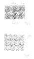
- FIG. 7 is an exemplary macroscopic photogram of a halftone measuring field.
- FIG. 8 is a gray scale value diagram of the halftone measuring field or macroscopic photogram of FIG. 7 .
- FIG. 9 is another exemplary macroscopic photogram of a halftone measuring field.
- FIG. 10 is a gray scale value diagram of the halftone measuring field or macroscopic photogram of FIG. 9 .
- the present invention provides a method for determining parameters relevant to the print quality of a printed product, namely for verifying whether an inspected measuring field of the printed product is printed neatly and with adequate quality.
- inspecting measuring fields of a print control strip 20 namely with the aid of a camera 21 that features a macro lens
- the camera 21 can consist of a miniature high-resolution camera that records at least one measuring photograph of the measuring fields of the print control strip 20 to be inspected, namely a so-called macroscopic photogram.
- the term “macroscopic photogram” refers to a measuring photograph that is recorded with the aid of a camera featuring a macro lens a short distance from the measuring field to be inspected. Details of the inspected measuring field are magnified in the corresponding macroscopic photogram similar to a magnifier.
- the magnification factor of the macro lens of the camera 21 is preferably between 20 and 50.
- a print control strip 20 with a total of twelve measuring fields 22 is shown. Some measuring fields 22 are in the form of a full-tone measuring fields 22 a and other measuring fields are in the form of halftone measuring fields 22 b .
- the camera 21 featuring the macro lens can be mounted on a crossbeam and can be displaced relative to the print control strip 20 as indicated by the double arrow 23 in order to inspect each measuring field 22 thereof.
- the camera 21 can be in the form of a separate component that can be displaced relative to the print control strip 20 independently of other components in order to inspect the measuring fields 22 .
- the camera 21 can be integrated into a measuring head that contains a densitometer and/or a colorimetric measuring device and in which the camera can be displaced relative to the print control strip 20 together with the densitometer and/or the colorimetric measuring device in order to inspect the measuring fields 22 .
- the inventive method for determining the print quality of a measuring field 22 with the aid of a camera 21 at least one macroscopic photogram of the measuring field 22 is recorded in a first step 24 .
- the macroscopic photogram or each macroscopic photogram is evaluated in a step 25 with the aid of an image processing method in order to determine at least one actual value of at least one parameter of the inspected measuring field 22 that is relevant to the print quality.
- each determined actual value is compared with a corresponding nominal value in order to verify that the measuring field is printed or printed out with high or adequate quality. If it is determined that the measuring field is not printed out or printed with the required quality, an alarm or error message can be generated at the printing machine in a subsequent step 27 based on the comparison between the actual value and the nominal value carried out in step 26 .
- the camera 21 can be in the form of a multi-bit camera, particularly an 8-bit camera that inspects a measuring field 22 in the so-called RGB-channels and preferably outputs a macroscopic photogram of the measuring field 22 and a gray scale value diagram of the macroscopic photogram or the measuring field 22 for each RGB-channel.
- a total of 256 gray scale values can be illustrated in the gray scale value diagram.
- FIG. 3 A macroscopic photogram of a measuring field in the form of the full-tone measuring field 22 a and printed with a special printing ink is shown in FIG. 3 .
- FIG. 4 is a gray scale value diagram 28 of the macroscopic photogram of FIG. 3 and therefore of the full-tone measuring field 22 a that is made available by the camera 20 in the complementary RGB-channel relative to the printing ink of the full-tone measuring field 22 a .
- the image coordinates of the macroscopic photogram of the full-tone measuring field 22 a are plotted on the X-coordinate and the Y-coordinate of the gray scale value diagram 28 .
- the gray scale values in the respective pixel of the macroscopic photogram of the full-tone measuring field 22 a are plotted on the Z-coordinate.
- the gray scale value diagram 28 of FIG. 4 comprises a so-called inverted gray scale value diagram, in which a gray scale value of zero corresponds to the maximum color value of the full-tone measuring field 22 a such that deviations from this maximum color value appear in the form of peaks in the gray scale value diagram 28 of the macroscopic photogram of the full-tone measuring field 22 a .
- An actual value for the full-tone measuring field 22 a in the form of a uniformity distribution of the gray scale values over the image coordinates of the macroscopic photogram of the full-tone measuring field 22 a or a noise of the gray scale value over the macroscopic photogram or the full-tone measuring field 22 a can be determined from the gray scale value diagram 28 . It can be concluded that a full-tone measuring field 22 a of adequate print quality is examined if the uniformity distribution or the noise is respectively lower than the corresponding nominal value or limiting value as shown in the embodiment according to FIGS. 3 and 4 .
- FIG. 6 is a gray scale value diagram 29 in the macroscopic photogram of a full-tone measuring field 22 a according to FIG. 5 , in which substantially larger deviations of the gray scale values are concluded over the image coordinates of the macroscopic photogram of the full-tone measuring field 22 a .
- the uniformity distribution and the noise of the gray scale values are higher than the corresponding nominal value or limiting value in numerous pixels from which it can be determined that a full-tone measuring field 22 a of inferior print quality is examined in this case.
- the uniformity distribution or the noise of the gray scale values is determined relative to a nominal value or a limiting value based on the image coordinates of the full-tone measuring field 22 a or the image coordinates of the macroscopic photogram of the full-tone measuring field in order to carry out a qualitative evaluation of the full-tone measuring field 22 a .
- FIG. 7 is a macroscopic photogram of a halftone measuring field 22 b in the region of six halftone dots.
- the halftone dots are in the form of round halftone dots in the illustrated embodiment. Any other shape of halftone dots may also be chosen in a halftone measuring field 22 b instead of all round halftone dots.
- at least one macroscopic photogram of the halftone measuring field 22 b is recorded, according to the invention, with the aid of a camera that features a macro lens.
- An actual value of at least one parameter relevant to the print quality is determined from each macroscopic photogram using an image processing method.
- each actual value consists of a geometric parameter of the halftone dots of the halftone measuring field 22 b . It can be concluded that a halftone measuring field of adequate print quality is examined if each geometric parameter is lower than the corresponding nominal value or limiting value, and that a halftone measuring field 22 b of inferior print quality is examined if each geometric parameter is higher than the corresponding nominal limiting value.
- the most frequent gray scale values are determined with the aid of a gray scale value diagram 30 of the halftone measuring field 22 b using an image processing method so as to define a geometric parameter for round halftone dots of a halftone measuring field 22 b .
- all image information that lies outside the most frequent gray scale values is filtered out of the macroscopic photogram.
- a minimum halftone dot diameter D MIN and a maximum halftone dot diameter D MAX are determined for each halftone dot by utilizing the correspondingly filtered macroscopic photogram of the halftone measuring field 22 b .
- a first halftone dot deformation value is determined for each halftone dot from the minimum halftone dot diameters D MIN and the maximum halftone dot diameters D MAX by utilizing the following formula:
- RPDW 1 D MAX - D MIN D MAX * 100 ⁇ % wherein RPDW 1 is the first halftone dot deformation value of a halftone dot, D MAX is the maximum halftone dot diameter of a halftone dot and D MIN is the minimum halftone dot diameter of a halftone dot.
- the halftone dot deformation value RPDW 1 of the halftone dots is consequently relatively small as shown in the example of the filtered macroscopic photogram of the halftone measuring field 22 b in FIGS. 7 and 8 , it can be concluded that the halftone dots of the halftone measuring field 22 b are round and printed with adequate quality.
- the minimum halftone dot diameter D MIN and the maximum halftone dot diameter D MAX deviate significantly and the first halftone dot deformation value RPDW 1 is consequently relatively large as shown in the example of the filtered macroscopic photogram of the halftone measuring field 22 b in FIGS. 9 and 10 , it can be concluded that the halftone dots have an inferior print quality and that doubling of the halftone dots has occurred. This means that the print quality of the halftone dots increases proportionally to the decrease in the difference between the minimum and the maximum halftone dot diameter.
- the difference between a halftone measuring field 22 b of adequate print quality according to FIG. 7 and a halftone measuring field 22 b of inferior print quality according to FIG. 9 can also be determined based on a comparison between the corresponding gray scale value diagrams 30 and 31 according to FIGS. 8 and 9 , which again consist of inverted gray scale value diagrams.
- the gray scale value diagram 30 according to FIG. 8 of a halftone measuring field 22 b of adequate print quality is characterized by round and defined transitions between adjacent halftone dots.
- the gray scale value diagram 31 of a halftone measuring field 22 b of inferior print quality shows undefined and unround transitions.
- another geometric parameter in the form of a second halftone dot deformation value can be determined for each round halftone dot of a halftone measuring field in addition to the above-mentioned first halftone dot deformation value, namely from a minimum surface of a halftone dot that is determined for a first defined gray scale value range and from a maximum surface of a halftone dot that is determined for a second defined gray scale value range.
- all pixels of the macroscopic photogram of the halftone measuring field that lie outside the first gray scale value range are filtered out with the aid of an image processing method after the first gray scale value range is defined.
- the minimum surface of the halftone dots of the halftone measuring field can then be calculated within this first gray scale value range.
- the gray scale value range is increased and the maximum surface of the halftone dots is determined within this gray scale value range.
- the second halftone dot deformation value is then calculated for each halftone dot from the minimum halftone dot surfaces and the maximum halftone dot surfaces by utilizing the following formula:
- RPDW 2 A MAX - A MIN A MIN * 100 ⁇ ⁇ % wherein RPDW 2 is the second halftone dot deformation value of a halftone dot, A MAX is the maximum surface of a halftone dot and A MIN is the minimum surface of a halftone dot.
- the inventive method also makes it possible to detect smearing at the beginning of the printing process by analyzing the edges of a print control strip that was printed transverse to the transport direction of the material to be printed in the above-described fashion at the beginning of the printing process.
- the inventive method for determining whether measuring fields of a printed product have an adequate print quality can be advantageously combined with a color control method in such a way that the actual values determined in the measuring fields with the aid of a densitometer and/or a colorimetric measuring device are only used for control purposes if it was determined beforehand that the measuring field has an adequate quality with the aid of the inventive method.
Abstract
Description
wherein RPDW1 is the first halftone dot deformation value of a halftone dot, DMAX is the maximum halftone dot diameter of a halftone dot and DMIN is the minimum halftone dot diameter of a halftone dot.
wherein RPDW2 is the second halftone dot deformation value of a halftone dot, AMAX is the maximum surface of a halftone dot and AMIN is the minimum surface of a halftone dot.
- 20 Print control strip
- 21 Camera
- 22 Measuring field
- 22 a Full-tone measuring field
- 22 b Halftone measuring field
- 23 Double arrow
- 24 Step
- 25 Step
- 26 Step
- 27 Step
- 28 Gray scale value diagram
- 29 Gray scale value diagram
- 30 Gray scale value diagram
- 31 Gray scale value diagram
Claims (6)
Priority Applications (1)
| Application Number | Priority Date | Filing Date | Title |
|---|---|---|---|
| US11/732,554 US8089667B2 (en) | 2007-04-04 | 2007-04-04 | Method for determining parameters relevant to the print quality of a printed product |
Applications Claiming Priority (1)
| Application Number | Priority Date | Filing Date | Title |
|---|---|---|---|
| US11/732,554 US8089667B2 (en) | 2007-04-04 | 2007-04-04 | Method for determining parameters relevant to the print quality of a printed product |
Publications (2)
| Publication Number | Publication Date |
|---|---|
| US20080246979A1 US20080246979A1 (en) | 2008-10-09 |
| US8089667B2 true US8089667B2 (en) | 2012-01-03 |
Family
ID=39826616
Family Applications (1)
| Application Number | Title | Priority Date | Filing Date |
|---|---|---|---|
| US11/732,554 Expired - Fee Related US8089667B2 (en) | 2007-04-04 | 2007-04-04 | Method for determining parameters relevant to the print quality of a printed product |
Country Status (1)
| Country | Link |
|---|---|
| US (1) | US8089667B2 (en) |
Cited By (1)
| Publication number | Priority date | Publication date | Assignee | Title |
|---|---|---|---|---|
| US20120180561A1 (en) * | 2011-01-13 | 2012-07-19 | Heidelberger Druckmaschinen Aktiengesellschaft | Method and apparatus for determining a curing level of printing inks and print process control strip |
Citations (4)
| Publication number | Priority date | Publication date | Assignee | Title |
|---|---|---|---|---|
| US4200932A (en) * | 1977-06-25 | 1980-04-29 | Roland Offsetmaschinenfabrik Faber & Schleicher Ag. | Means for the control and regulation of the printing process on printing presses |
| US5372921A (en) * | 1993-11-02 | 1994-12-13 | Eastman Kodak Company | High-contrast photographic elements with enhanced safelight performance |
| US20050105111A1 (en) * | 2003-10-23 | 2005-05-19 | Hans Ott | Color quality assessment and color control during color reproduction |
| US20060152706A1 (en) * | 2004-03-19 | 2006-07-13 | Butland Charles L | Multi-modal authentication, anti-diversion and asset management and method |
-
2007
- 2007-04-04 US US11/732,554 patent/US8089667B2/en not_active Expired - Fee Related
Patent Citations (5)
| Publication number | Priority date | Publication date | Assignee | Title |
|---|---|---|---|---|
| US4200932A (en) * | 1977-06-25 | 1980-04-29 | Roland Offsetmaschinenfabrik Faber & Schleicher Ag. | Means for the control and regulation of the printing process on printing presses |
| US4200932B1 (en) * | 1977-06-25 | 1983-04-26 | ||
| US5372921A (en) * | 1993-11-02 | 1994-12-13 | Eastman Kodak Company | High-contrast photographic elements with enhanced safelight performance |
| US20050105111A1 (en) * | 2003-10-23 | 2005-05-19 | Hans Ott | Color quality assessment and color control during color reproduction |
| US20060152706A1 (en) * | 2004-03-19 | 2006-07-13 | Butland Charles L | Multi-modal authentication, anti-diversion and asset management and method |
Cited By (2)
| Publication number | Priority date | Publication date | Assignee | Title |
|---|---|---|---|---|
| US20120180561A1 (en) * | 2011-01-13 | 2012-07-19 | Heidelberger Druckmaschinen Aktiengesellschaft | Method and apparatus for determining a curing level of printing inks and print process control strip |
| US9170195B2 (en) * | 2011-01-13 | 2015-10-27 | Heidelberger Druckmaschinen Ag | Method and apparatus for determining a curing level of printing inks and print process control strip |
Also Published As
| Publication number | Publication date |
|---|---|
| US20080246979A1 (en) | 2008-10-09 |
Similar Documents
| Publication | Publication Date | Title |
|---|---|---|
| JP6738269B2 (en) | Method for checking image inspection system | |
| US7260244B2 (en) | Print inspection method and print inspection apparatus | |
| US10623605B2 (en) | Method for image inspection of printed products using adaptive image smoothing | |
| EP0636475A1 (en) | Automatic inspection of printing plates or cylinders | |
| US11254119B2 (en) | Image inspection method with local image rectification | |
| CN109507207A (en) | The image detection of maculature management and the printed matter with defect type | |
| EP3428625A1 (en) | Printing result inspection device and method | |
| US10564110B2 (en) | Printing result inspection apparatus and method | |
| US20100039510A1 (en) | Method and DEVICE for PRINT INSPECTION | |
| KR100827906B1 (en) | Substrate inspection device | |
| JP2011209105A (en) | Image inspection apparatus and printing equipment, and method of inspecting image | |
| US8089667B2 (en) | Method for determining parameters relevant to the print quality of a printed product | |
| JP2005182143A (en) | Inspection method for cap top surface | |
| JP2013257197A (en) | Performance evaluation sheet for printed matter inspection device | |
| CN101947880A (en) | Determine the method for the quality degree of the product handled by processor | |
| JP2004251855A (en) | Method for inspecting external surface of can | |
| US11908126B2 (en) | Method of controlling the quality of printed products by image inspection filtering | |
| CN115760856B (en) | Image recognition-based part spacing measurement method, system and storage medium | |
| CN113256554B (en) | Deterministic image inspection | |
| JPH08207258A (en) | Method and device for detecting periodical continuous defect of printed matter | |
| JP2017116487A (en) | Web defect inspection apparatus | |
| JP3110594B2 (en) | Inspection method of stamped characters | |
| JP4275582B2 (en) | Board inspection equipment | |
| JP2015064303A (en) | Unevenness detection device of peripheral part, and unevenness detection method of peripheral part | |
| JP2010266309A (en) | Appearance inspection device for color filter and appearance inspection method |
Legal Events
| Date | Code | Title | Description |
|---|---|---|---|
| AS | Assignment |
Owner name: MAN ROLAND DRUCKMASCHINEN AG, GERMANY Free format text: ASSIGNMENT OF ASSIGNORS INTEREST;ASSIGNORS:GUGLER, CHRISTIAN;HAUCK, SHAHRAM;REEL/FRAME:019325/0327;SIGNING DATES FROM 20070424 TO 20070426 Owner name: MAN ROLAND DRUCKMASCHINEN AG, GERMANY Free format text: ASSIGNMENT OF ASSIGNORS INTEREST;ASSIGNORS:GUGLER, CHRISTIAN;HAUCK, SHAHRAM;SIGNING DATES FROM 20070424 TO 20070426;REEL/FRAME:019325/0327 |
|
| AS | Assignment |
Owner name: MANROLAND AG, GERMANY Free format text: CHANGE OF NAME;ASSIGNOR:MAN ROLAND DRUCKMASCHINEN AG;REEL/FRAME:022024/0567 Effective date: 20080115 Owner name: MANROLAND AG,GERMANY Free format text: CHANGE OF NAME;ASSIGNOR:MAN ROLAND DRUCKMASCHINEN AG;REEL/FRAME:022024/0567 Effective date: 20080115 |
|
| ZAAA | Notice of allowance and fees due |
Free format text: ORIGINAL CODE: NOA |
|
| ZAAB | Notice of allowance mailed |
Free format text: ORIGINAL CODE: MN/=. |
|
| ZAAA | Notice of allowance and fees due |
Free format text: ORIGINAL CODE: NOA |
|
| FEPP | Fee payment procedure |
Free format text: PAYOR NUMBER ASSIGNED (ORIGINAL EVENT CODE: ASPN); ENTITY STATUS OF PATENT OWNER: LARGE ENTITY |
|
| STCF | Information on status: patent grant |
Free format text: PATENTED CASE |
|
| AS | Assignment |
Owner name: MANROLAND SHEETFED GMBH, GERMANY Free format text: ASSIGNMENT OF ASSIGNORS INTEREST;ASSIGNOR:MANROLAND AG;REEL/FRAME:029757/0165 Effective date: 20121220 |
|
| FPAY | Fee payment |
Year of fee payment: 4 |
|
| AS | Assignment |
Owner name: GRAPHO METRONIC MESS- UND REGELTECHNIK GMBH, GERMA Free format text: ASSIGNMENT OF ASSIGNORS INTEREST;ASSIGNOR:MANROLAND SHEETFED GMBH;REEL/FRAME:043343/0320 Effective date: 20170728 |
|
| MAFP | Maintenance fee payment |
Free format text: PAYMENT OF MAINTENANCE FEE, 8TH YEAR, LARGE ENTITY (ORIGINAL EVENT CODE: M1552); ENTITY STATUS OF PATENT OWNER: LARGE ENTITY Year of fee payment: 8 |
|
| FEPP | Fee payment procedure |
Free format text: MAINTENANCE FEE REMINDER MAILED (ORIGINAL EVENT CODE: REM.); ENTITY STATUS OF PATENT OWNER: LARGE ENTITY |
|
| LAPS | Lapse for failure to pay maintenance fees |
Free format text: PATENT EXPIRED FOR FAILURE TO PAY MAINTENANCE FEES (ORIGINAL EVENT CODE: EXP.); ENTITY STATUS OF PATENT OWNER: LARGE ENTITY |
|
| STCH | Information on status: patent discontinuation |
Free format text: PATENT EXPIRED DUE TO NONPAYMENT OF MAINTENANCE FEES UNDER 37 CFR 1.362 |
|
| FP | Lapsed due to failure to pay maintenance fee |
Effective date: 20240103 |