US8091546B2 - Method and apparatus for humidification and warming of air - Google Patents
Method and apparatus for humidification and warming of air Download PDFInfo
- Publication number
- US8091546B2 US8091546B2 US12/627,454 US62745409A US8091546B2 US 8091546 B2 US8091546 B2 US 8091546B2 US 62745409 A US62745409 A US 62745409A US 8091546 B2 US8091546 B2 US 8091546B2
- Authority
- US
- United States
- Prior art keywords
- gas
- humidification
- heater
- temperature
- fluid communication
- Prior art date
- Legal status (The legal status is an assumption and is not a legal conclusion. Google has not performed a legal analysis and makes no representation as to the accuracy of the status listed.)
- Expired - Fee Related, expires
Links
- 238000000034 method Methods 0.000 title claims abstract description 12
- 238000010792 warming Methods 0.000 title claims description 5
- 239000000463 material Substances 0.000 claims abstract description 67
- 239000012530 fluid Substances 0.000 claims description 26
- 238000004891 communication Methods 0.000 claims description 14
- 239000003814 drug Substances 0.000 claims description 9
- 239000000443 aerosol Substances 0.000 claims description 2
- 238000003780 insertion Methods 0.000 claims description 2
- 230000037431 insertion Effects 0.000 claims description 2
- 238000012544 monitoring process Methods 0.000 claims description 2
- CURLTUGMZLYLDI-UHFFFAOYSA-N Carbon dioxide Chemical compound O=C=O CURLTUGMZLYLDI-UHFFFAOYSA-N 0.000 claims 2
- 229910002092 carbon dioxide Inorganic materials 0.000 claims 1
- 239000001569 carbon dioxide Substances 0.000 claims 1
- 239000007789 gas Substances 0.000 description 120
- 239000004033 plastic Substances 0.000 description 9
- 229920003023 plastic Polymers 0.000 description 9
- 229940079593 drug Drugs 0.000 description 7
- 239000002184 metal Substances 0.000 description 6
- 229910052751 metal Inorganic materials 0.000 description 6
- 238000011144 upstream manufacturing Methods 0.000 description 4
- 230000002745 absorbent Effects 0.000 description 3
- 239000002250 absorbent Substances 0.000 description 3
- 239000003990 capacitor Substances 0.000 description 3
- 230000002950 deficient Effects 0.000 description 3
- 238000010438 heat treatment Methods 0.000 description 3
- 230000005484 gravity Effects 0.000 description 2
- 238000001802 infusion Methods 0.000 description 2
- 239000000203 mixture Substances 0.000 description 2
- 125000006850 spacer group Chemical group 0.000 description 2
- 239000008223 sterile water Substances 0.000 description 2
- XLYOFNOQVPJJNP-UHFFFAOYSA-N water Chemical compound O XLYOFNOQVPJJNP-UHFFFAOYSA-N 0.000 description 2
- 238000004804 winding Methods 0.000 description 2
- 229920000742 Cotton Polymers 0.000 description 1
- 239000004677 Nylon Substances 0.000 description 1
- 239000000654 additive Substances 0.000 description 1
- 229910052782 aluminium Inorganic materials 0.000 description 1
- XAGFODPZIPBFFR-UHFFFAOYSA-N aluminium Chemical compound [Al] XAGFODPZIPBFFR-UHFFFAOYSA-N 0.000 description 1
- 230000004888 barrier function Effects 0.000 description 1
- 238000010586 diagram Methods 0.000 description 1
- 230000003028 elevating effect Effects 0.000 description 1
- 230000008020 evaporation Effects 0.000 description 1
- 238000001704 evaporation Methods 0.000 description 1
- 239000000835 fiber Substances 0.000 description 1
- -1 for example Substances 0.000 description 1
- 238000009413 insulation Methods 0.000 description 1
- 239000012774 insulation material Substances 0.000 description 1
- 230000001788 irregular Effects 0.000 description 1
- 239000007788 liquid Substances 0.000 description 1
- 238000004519 manufacturing process Methods 0.000 description 1
- 238000002483 medication Methods 0.000 description 1
- 238000012986 modification Methods 0.000 description 1
- 230000004048 modification Effects 0.000 description 1
- 239000012811 non-conductive material Substances 0.000 description 1
- 229920001778 nylon Polymers 0.000 description 1
- 239000004417 polycarbonate Substances 0.000 description 1
- 229920000515 polycarbonate Polymers 0.000 description 1
- 230000001953 sensory effect Effects 0.000 description 1
- 238000001179 sorption measurement Methods 0.000 description 1
- 239000012899 standard injection Substances 0.000 description 1
- 239000000126 substance Substances 0.000 description 1
- 238000001356 surgical procedure Methods 0.000 description 1
Images


Classifications
-
- A—HUMAN NECESSITIES
- A61—MEDICAL OR VETERINARY SCIENCE; HYGIENE
- A61M—DEVICES FOR INTRODUCING MEDIA INTO, OR ONTO, THE BODY; DEVICES FOR TRANSDUCING BODY MEDIA OR FOR TAKING MEDIA FROM THE BODY; DEVICES FOR PRODUCING OR ENDING SLEEP OR STUPOR
- A61M13/00—Insufflators for therapeutic or disinfectant purposes, i.e. devices for blowing a gas, powder or vapour into the body
- A61M13/003—Blowing gases other than for carrying powders, e.g. for inflating, dilating or rinsing
-
- A—HUMAN NECESSITIES
- A61—MEDICAL OR VETERINARY SCIENCE; HYGIENE
- A61M—DEVICES FOR INTRODUCING MEDIA INTO, OR ONTO, THE BODY; DEVICES FOR TRANSDUCING BODY MEDIA OR FOR TAKING MEDIA FROM THE BODY; DEVICES FOR PRODUCING OR ENDING SLEEP OR STUPOR
- A61M16/00—Devices for influencing the respiratory system of patients by gas treatment, e.g. mouth-to-mouth respiration; Tracheal tubes
- A61M16/10—Preparation of respiratory gases or vapours
- A61M16/14—Preparation of respiratory gases or vapours by mixing different fluids, one of them being in a liquid phase
- A61M16/16—Devices to humidify the respiration air
-
- A—HUMAN NECESSITIES
- A61—MEDICAL OR VETERINARY SCIENCE; HYGIENE
- A61M—DEVICES FOR INTRODUCING MEDIA INTO, OR ONTO, THE BODY; DEVICES FOR TRANSDUCING BODY MEDIA OR FOR TAKING MEDIA FROM THE BODY; DEVICES FOR PRODUCING OR ENDING SLEEP OR STUPOR
- A61M2205/00—General characteristics of the apparatus
- A61M2205/33—Controlling, regulating or measuring
- A61M2205/3368—Temperature
-
- A—HUMAN NECESSITIES
- A61—MEDICAL OR VETERINARY SCIENCE; HYGIENE
- A61M—DEVICES FOR INTRODUCING MEDIA INTO, OR ONTO, THE BODY; DEVICES FOR TRANSDUCING BODY MEDIA OR FOR TAKING MEDIA FROM THE BODY; DEVICES FOR PRODUCING OR ENDING SLEEP OR STUPOR
- A61M2205/00—General characteristics of the apparatus
- A61M2205/36—General characteristics of the apparatus related to heating or cooling
- A61M2205/362—General characteristics of the apparatus related to heating or cooling by gas flow
-
- A—HUMAN NECESSITIES
- A61—MEDICAL OR VETERINARY SCIENCE; HYGIENE
- A61M—DEVICES FOR INTRODUCING MEDIA INTO, OR ONTO, THE BODY; DEVICES FOR TRANSDUCING BODY MEDIA OR FOR TAKING MEDIA FROM THE BODY; DEVICES FOR PRODUCING OR ENDING SLEEP OR STUPOR
- A61M2206/00—Characteristics of a physical parameter; associated device therefor
- A61M2206/10—Flow characteristics
- A61M2206/14—Static flow deviators in tubes disturbing laminar flow in tubes, e.g. archimedes screws
-
- Y—GENERAL TAGGING OF NEW TECHNOLOGICAL DEVELOPMENTS; GENERAL TAGGING OF CROSS-SECTIONAL TECHNOLOGIES SPANNING OVER SEVERAL SECTIONS OF THE IPC; TECHNICAL SUBJECTS COVERED BY FORMER USPC CROSS-REFERENCE ART COLLECTIONS [XRACs] AND DIGESTS
- Y10—TECHNICAL SUBJECTS COVERED BY FORMER USPC
- Y10S—TECHNICAL SUBJECTS COVERED BY FORMER USPC CROSS-REFERENCE ART COLLECTIONS [XRACs] AND DIGESTS
- Y10S261/00—Gas and liquid contact apparatus
- Y10S261/65—Vaporizers
Definitions
- the present invention relates to an apparatus and method used to humidify and/or warm a gas prior to its use in a surgical or other medical procedure.
- the flow rate should be approximately 20 liters per minute, the relative humidity should be approximately 80 to 100 percent, and the temperature approximately 90 to 105 degrees Fahrenheit. Most prior art devices cannot meet or exceed these ideal characteristics.
- the flow rate of many prior devices is well below 20 liters per minute. Commonly, the flow rate of prior devices has been generally 12 to 14 liters per minute. Most of these devices generally operate by forcing the gas through the humidification material, thereby requiring a high degree of pressure. This increased pressure reduces the flow rate of the gas even further.
- One aspect of the present invention regards a gas humidification apparatus that includes an inlet, a humidification device in fluid communication with the inlet, the humidification device having a humidification material that readily absorbs moisture and readily releases moisture when exposed to a dry environment, wherein the humidification material has a configuration that generates turbulence in a gas as it passes over a surface of the humidification material and an outlet in fluid communication with the humidification device.
- a second aspect of the present invention regards a gas humidification apparatus that includes an inlet, a humidification device in fluid communication with the inlet, the humidification device having a humidification material that readily absorbs moisture and readily releases moisture when exposed to a dry environment, wherein the humidification material is placed within a shell that has a configuration that generates turbulence in a gas as it passes over a surface of the shell and an outlet in fluid communication with the humidification device.
- a third aspect of the present invention regards a gas humidification apparatus that includes an inlet, a humidification device in fluid communication with the inlet, the humidification device having a heater housing that includes a heater and a plurality of openings.
- a humidification material that readily absorbs moisture and readily releases moisture when exposed to a dry environment and an outlet in fluid communication with the humidification device.
- a fourth aspect of the present invention regards a gas humidification apparatus that includes inlet means for supplying a gas, turbulence means for generating turbulence in the gas and outlet means for expelling the turbulent gas from the gas humidification apparatus.
- a fifth aspect of the present invention regards a method of humidifying a gas that includes supplying a gas to a surface of a humidification material that readily absorbs moisture and readily releases moisture when exposed to a dry environment and generating turbulence in gas as it passes over the surface of the humidification material.
- a sixth aspect of the present invention regards a method of humidifying a gas that includes warming a gas, humidifying the gas and placing a catheter in fluid communication with the gas during the humidifying.
- a seventh aspect of the present invention regards a gas apparatus that includes an inlet, a heater in fluid communication with the inlet and a temperature sensor for measuring a temperature of a gas that flows within the gas apparatus in an indirect manner.
- An eighth aspect of the present invention regards a method of humidifying a gas that includes warming a gas, humidifying the gas and flowing the gas over a surface of a humidifier.
- Each of the above aspects provides the advantage of supplying a patient with warmed and/or humidified gas at or near preferred rates, humidity and/or temperature.
- FIG. 1 shows a first embodiment of a gas warmer and/or humidifier apparatus according to the present invention
- FIG. 2 shows a second embodiment of a gas warmer and/or humidifier apparatus according to the present invention having a plurality of baffles in the shell;
- FIG. 3 shows a third embodiment of a gas warmer and/or humidifier apparatus according to the present invention having an external temperature or humidity sensor;
- FIG. 4 shows a cross section perspective view of a gas warmer and/or humidifier apparatus
- FIG. 5 shows a perspective exploded view of a fourth embodiment of gas humidification apparatus according to the present invention.
- FIG. 6 shows a right top side perspective view of the gas humidification apparatus of FIG. 5 ;
- FIG. 7 shows a right bottom side perspective view of the gas humidification apparatus of FIG. 5 ;
- FIG. 8 shows a top view of the gas humidification apparatus of FIG. 5 ;
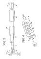
- FIG. 9 shows a right side view of the gas humidification apparatus of FIG. 5 ;
- FIG. 10 shows a front view of the gas humidification apparatus of FIG. 5 ;
- FIG. 11 shows a rear side perspective view of the gas humidification apparatus of FIG. 5 ;
- FIG. 12 shows a top view of an embodiment of a humidification material to be used with the gas humidification apparatus of FIG. 5 ;
- FIG. 13 shows a perspective view of a fifth embodiment of gas humidification apparatus according to the present invention.
- FIG. 14 shows a side view of the gas humidification apparatus of FIG. 13 ;
- FIG. 15 shows a partially exposed side view of the gas humidification apparatus of FIG. 13 ;
- FIG. 16 shows a right front side and partially exposed perspective view of the gas humidification apparatus of FIG. 13 ;
- FIG. 17 shows a right rear side and partially exposed perspective view of the gas humidification apparatus of FIG. 13 ;
- FIG. 18 shows a circuit diagram of heating circuit that can be used with the gas humidification apparatus/gas warmer and/or heater apparatus of FIGS. 1-17 .
- FIG. 1 shows one embodiment of the gas warmer and humidification apparatus.
- FIG. 1 shows the apparatus used in conjunction with an insufflation device.
- FIGS. 1-3 show the apparatus 1 associated with the insufflation tubing 10 .
- the apparatus is located downstream from the gas source for the insufflation device where downstream refers to a location closer to output of the insufflation tubing 10 or a patient.
- the apparatus 1 has an upstream end located nearer to the gas source and a downstream end located closer to the patient.
- the gas warmer and humidifier apparatus 1 may be constructed as a re-useable or disposable product.
- a gas inlet port 12 is located at an upstream end of the apparatus 1 and associable with the insulation tubing 10 .
- a plurality of plugs 14 may also be located at the upstream end of the apparatus 1 .
- the plugs 14 may be male leads for association with the heater 18 and/or a thermocouple and/or other suitable sensing devices. It is to be understood that the location at the upstream end is variable and other locations consistent with the characteristics of the plugs 14 are envisioned.
- the apparatus 1 includes a heater 18 . Surrounding the heater 18 is a core 20 . The core 20 maintains the heater 18 in a significantly watertight environment. About the core 20 is a humidification material 24 . The humidification material 24 generally envelops the entire core 20 . The humidification material 24 may only partially envelop the core 20 as well. A shell 26 , acting as a housing, surrounds humidification material 24 . At the downstream end of the apparatus 1 may be a gas outlet 28 associable with a downstream portion of the insufflation tube 10 .
- the heater 18 of the above embodiment may include a conventional cartridge heater, a heat generating wire, a light bulb, or other heat generating device capable of creating an elevated temperature that can radiate from the surface of the heater. As shown in FIG. 1 , the heater 18 is insertable within a core 20 of non-conductive material. In further embodiments, as shown in FIG. 2 , the heater 18 and plugs 14 are molded into a single assembly that is then molded with the core 20 to make a single unit.
- the heater 18 can be a metal structure with integral sensing elements or external sensing elements. It can also be molded of a high temperature resistant plastic. Either the metal or the plastic heater 18 is disposable, although the lower cost of the plastic heater 18 may better suit it as a disposable heater 18 . Further, the disposability or re-usability of the apparatus 1 aids in maintaining the apparatus 1 sterile for any purposes that may require a sterile apparatus 1 .
- the heater 18 has approximately 36 watts of power although heaters 18 with other wattage, such as between 10 watts and 50 watts, can also be used.
- the heater 18 typically is approximately 1 to 5 inches long, preferably approximately 11 ⁇ 2 to 3 inches long, but other sizes can be used depending on the physical size of the other components, and the amount of humidity to be generated.
- the heater 18 may be connected to control circuitry 100 controls the amount of heat and rate of heat generated by the heater 18 . As shown in FIG.
- the control circuitry 100 includes one or more temperature sensors 102 and a control system 104 to regulate the degree of energy supplied to the heater 18 by modulating the current supplied to the heater via turning on/off the current and raising or lowering the current.
- the temperature sensors 102 each independently measure the temperature of the core 20 .
- the temperature signals from temperature sensors 102 are continuously fed to amplifiers 105 .
- the two signals are compared with each other and if it is determined that the difference between the signals reaches or exceeds a predetermined level, such as 5° C., then the control system 104 turns off the current drivers 106 and the current supplied to the heater 18 .
- the current drivers 106 are turned off because reaching or exceeding the predetermined level denotes that one or both of the sensors 102 are defective and need to be replaced.
- the control system 104 includes four identical current drivers 106 that are in parallel with one another as shown in FIG. 18 .
- Each driver 106 provides an output that is identical with the outputs of the other three drivers 106 .
- the control system 104 will drive each of the outputs of the current drivers 106 with approximately a 25% duty cycle wave shape.
- the four drivers combined will provide approximately 100% drive to the heater 18 .
- Each driver 106 includes a capacitor 108 of 1000 ⁇ F in parallel with a fuse 110 .
- the capacitors 108 direct the current during its respective 25% duty cycle away from its corresponding fuse 110 .
- the corresponding capacitor 108 will charge up and allow current to flow through the corresponding fuse 110 . In less than approximately 2 seconds, the fuse 110 in the driver circuit 106 will create an open circuit, thus preventing uncontrolled current to flow to the heater 18 .
- the apparatus 1 can have wiring to the heater 18 permanently attached.
- the apparatus 1 can have wiring to the heater 18 constructed with an integral connector that can be molded into the apparatus 1 or connected/disconnected via a one time use tab connection system.
- the apparatus 1 can have wiring to the heater 18 with the terminations molded into a natural connector, so that the cabling can be plugged into it, reducing its cost.
- the electronic wiring used to provide power and to measure the temperature or humidity can be wired directly to the active elements and over molded.
- the output wires will be molded or inserted into the shell 26 in order to make the cord detachable from the apparatus 1 .
- the heater 18 may be controlled by conventional heater controllers as are available on the market, such as those made by Watlow. Controllers typically are designed to work with temperature sensing devices such as thermocouples resistance temperature detectors (RTD's) and or thermistors.
- RTD's resistance temperature detectors
- the apparatus 1 can be provided with additional circuitry to measure humidity using a humidity sensor.
- Humidity sensors are available through Omega Engineering located in Atlanta, Ga., which can supply both the sensor and circuitry for reading and display.
- the temperature of the gas and the humidity of the gas could be displayed with additional circuitry.
- a remote power unit, part of the insufflator, or part of any other device used in the Operating Room associated with endoscopic procedures could provide the additional circuitry to display this information. Based on the readings, adjustments could be made on the amount of moisture fed to the humidification material 24 , or how much heat should be applied, or both.
- control could also be tied to the insufflator to supply the circuitry mentioned above.
- control could dynamically control the variables to maintain optimum conditions.
- the core 20 may be made of, but not limited to, plastic or a sheet metal. Some of the plastics that may be used for the core 20 include polycarbonate, RytonTM, VespelTM, or any of the high temperature plastics. A sheet metal such as aluminum coated with a non-conductive substance may also be used for the core 20 .
- the apparatus 1 includes a humidification material 24 .
- the humidification material 24 both readily absorbs moisture and readily releases it when exposed to a dry environment. Materials such as nylon and cotton are just a few of the many commercially available fibers that can meet these requirements.
- the humidification material 24 can have a tubular inside and outside surface. Tubular refers to a smooth surface. Yet, it is envisioned in further embodiments that the humidification material 24 may have a patterned or varying 15 degrees of a non-smooth surface.
- the humidification material 24 used in the preferred embodiment has a smooth inner surface and a serrated or star-like shaped outer surface to maximize surface area in the shortest possible linear space.
- FIG. 4 shows the preferred embodiment including a first and a second section of the humidification material 24 .
- Each section of the humidification material 24 is approximately an inch long with an inner channel in intimate contact with the heater 18 .
- Each of these serrated sections is slid over the core 20 that contains the heater 18 .
- a 1 ⁇ 4 inch gap should be between the serrated sections.
- a plastic spacer may be inserted between the serrated sections to provide the gap.
- the first and second serrated sections should be set out of phase with each other to force turbulence of the gas and increase the surface area of the material as it passes over the sections.
- the first and second serrated sections can be formed from a single serrated material by cutting the single serrated material so that the two serrated sections are formed. After cutting, the two serrated sections are rotated relative to one another until the desired phase difference between the two sections is achieved.
- the flow of CO 2 gas over the absorbent material is affected by the shape of the absorbent material and/or the channel within the shell 26 .
- the absorbent humidification material 24 may be cylindrically shaped and surrounded by a coil used to direct the flow of CO 2 gas. As the CO 2 gas travels through the windings of the coil, warmth and humidity are transferred to the CO 2 gas. The external surfaces of the coil rest against the inside of the shell 26 forming a seal that forces the CO 2 gas to travel through or within the coil windings.
- the encased heater 18 elevates the temperature of the humidification material 24 thereby elevating the temperature of the moisture it contains.
- the elevated temperature of the moisture leads to the creation of a vapor absorbed into the gas as it flows over the humidification material 24 .
- the humidification material 24 has a configuration that presents a high surface area to the direction of gas flow to allow increased opportunity for the moisture to evaporate into the gas thereby humidifying the gas.
- turbulence of the gas is created by the interior of the shell 26 covering the humidification material 24 and heater 18 having a surface area that is of an irregular pattern or texture.
- This turbulence may be created using a variety of structures. These structures may be located, for example, on or as part of the shell 26 or humidification material 24 . Further example of a structure for creating turbulence may be a spiral barrier. In additional embodiments, other structures may be incorporated, for example, by being either attached to the humidification material 24 or interior of the shell 26 of the apparatus 1 .
- the moisture applied to the humidification material 24 can contain medications or additives that will evaporate and be carried along in the humidified gas to the patient.
- Levels of medication and/or fluid in the gas can be controlled by timed evaporation and adsorption rates. Fluid could be infused by syringe, gravity feed through tubing, or by any number of pumps, to retain proper saturation levels.
- the apparatus 1 will have a port 16 for the infusion of fluid for the production of moisture.
- Moisture may include sterile water, medication, or a mixture of fluids required for merely humidification or dispensing of medication.
- the port 16 can be of the standard injection port used typically in the medical industry, a valve, or any other device, which can open or close allowing for the entrance of the fluid.
- the apparatus 1 includes one or more temperature sensing devices (not shown) to regulate the heater 18 .
- Each temperature-sensing device can be a resistive temperature device (RTD), a thermister, or a thermocouple.
- a K type thermocouple is embedded inside the heater 18 to measure its temperature. Any number of heater controller manufacturers such as Watlow or Hot Watt can provide the temperature sensing and control device.
- the shell 26 is an oblong tube having an internal channel, but any shape that will accommodate the internal elements of the device is acceptable.
- the internal channel of the shell 26 will be smooth.
- any form of surface irregularity to promote turbulence without flow restriction is acceptable for the 15 internal channel of the shell 26 .
- the shell 26 has an output opening 28 and an input opening 12 for the gas.
- the shell 26 additionally has a fluid fill port 16 for the infusion of fluid.
- Overall length of the preferred embodiment will be between 31 ⁇ 2 and 4 inches.
- the apparatus 1 will weigh approximately four ounces.
- the shell 26 can be made of any suitable material, for example, metal or plastic.
- a humidity sensor 34 may be included in the apparatus 1 .
- Appropriate humidity sensors 34 can be obtained from Omega Corporation located in Atlanta, Ga.
- an external temperature sensing device 32 can be inserted in the insufflation tubing 10 just outside of the gas outlet 28 .
- This device 32 measures the downstream temperature of the gas.
- the temperature of the gas is related to the temperature of the heater 18 .
- the temperature sensing device located within the heater 18 measures the temperature of the heater 18 .
- the temperature of the gas is not directly measured. Rather, the resulting temperature of the gas correlates to the temperature of the heater.
- the warmed and humidified gas leaves the apparatus 1 through a gas outlet 28 .
- the gas outlet may be a series of holes.
- the gas then enters the insufflation tubing 10 for possible delivery to a patient.
- FIGS. 5-12 Another embodiment of a gas humidification apparatus is shown in FIGS. 5-12 .
- the gas humidification apparatus 201 can be used in conjunction with an insufflation device.
- the gas humidification apparatus 201 is located downstream from a gas source for the insufflation device.
- the gas humidification apparatus 201 may be constructed as a re-useable or disposable product.
- a gas inlet port 212 is attached through a side portion of a front cap 213 of the gas humidification apparatus 201 .
- an inlet port 215 is attached through a central portion of the front cap 213 .
- the inlet port 215 allows for electrical components and wiring to be inserted into the gas humidification apparatus 201 .
- the gas humidification apparatus 201 can be modified so that the ports 212 and 215 are interchanged with one another.
- the cap 213 includes an annular metallic heater housing 217 that is attached thereto.
- the heater housing 217 is in fluid communication with the gas inlet port 212 .
- the heater housing 217 contains a heater cartridge that is well known in the art. When activated the heater cartridge heats up the interior and body of the heater housing 217 so that gases within and outside the heater housing 217 are heated.
- the heater housing 217 also includes a plurality of circular holes 219 having a diameter of approximately 0.1′′ (0.254 cm). Other shapes and sizes for the holes 219 are possible, such as triangular and square shaped openings.
- the gas flows into the gas humidification apparatus 201 via the gas inlet port 212 , the gas flows into the heater housing 217 , where it is heated if necessary, and then flows out of the holes 219 .
- the holes 219 there are approximately sixteen holes 219 that are arranged equidistantly from one another along an annular ring. The holes 219 of the heater housing 217 improve the rate of heating of the gas within the gas humidification apparatus 201 and create turbulence for the gas flowing within the gas humidification apparatus 201 .
- Two of the holes 219 preferably have their own RTD sensor. These sensors operate in the same manner as the temperature sensors for the embodiments of FIGS. 1-4 . In particular, the temperature measured by the two sensors are compared with one another to determine if one or both of the sensory is defective.
- a rear cylindrical portion 223 of the heater housing 217 is snugly inserted into a cylindrical central opening of a humidification material 224 that is preferably made of the same material as the humidification materials 24 described previously with respect to FIGS. 1-4 .
- a washer 221 is fitted over the rear portion 223 and abuts against the rear face of the humidification material 224 and acts as a stop in that it prevents the humidification material 224 from slipping off of the rear portion 223 and being wedged into an outlet 228 .
- the gas humidification apparatus 201 can further include a plate 225 positioned between the front or proximal end of the humidification material 224 and the heater housing 217 . Since the holes 219 face the front end of the humidification material 224 , the plate 225 allows the gas to flow along the exposed side of the humidification material. Note that the gas will flow along the side of the humidification material with or without the presence of the plate 225 .
- the humidification material 224 has a star-like pattern with ten to twelve points that aid in generating turbulence in the gas within the gas humidification apparatus 201 in a similar manner that the humidification material 24 of FIGS. 1 and 4 do.
- a second humidification material 224 may be spaced from the first humidification material by a spacer and out of phase with the first humidification material in the same manner as described previously with respect to the embodiment of FIGS. 1 and 4 .
- the assembled humidification material 224 and washer 221 and the inlet port 215 and the heater housing 217 are inserted into a housing or shell 226 .
- the front cap 213 is screwed on or snap fit onto the heater housing 217 .
- the housing 226 is made of a suitable material, such as plastic or metal, and has a downstream outlet 228 that allows the gas to flow outside of the housing 226 .
- the housing 226 includes a port 216 that allows fluid to be infused by syringe, gravity feed through tubing, or by any number of pumps, to the humidification material 224 .
- the fluids infused may include sterile water, medication, or a mixture of fluids required for merely humidification or dispensing of medication.
- the interior end of the port 216 is positioned so that infused fluids drip into the housing 226 and are soaked up by the entire humidification material 224 by capillary action.
- the port 216 is similar to the port 16 described previously with respect to the embodiments of FIGS. 1-4 .
- the housing 226 is inserted into a sleeve or shroud 230 so that the port 216 is slid along a slit 232 formed in the sleeve 230 and the outlet 228 extends through a rear opening 234 of the sleeve 230 .
- the sleeve 230 is snap fit to the housing 226 .
- the sleeve 230 is made of a thermal insulation material that retains the heat within the housing 226 so that a person can handle the sleeve 230 without fear of being exposed to excessive heat and without significantly heating up the ambient atmosphere.
- the sleeve 230 , the housing 226 and the humidification material 224 may be disposable while the cap 213 and its attached heater housing 217 may be reusable.
- the gas humidification apparatus 201 may include the temperature sensors, humidity sensors and control circuitry previously described with respect to the embodiments of FIGS. 14 and 18 so that the temperature and humidity of the gas flowing within the apparatus and delivered to a patient via outlet 228 is controlled.
- FIGS. 13-17 Another embodiment of a gas humidification apparatus is shown in FIGS. 13-17 .
- the gas humidification apparatus 301 essentially has the same structure as the gas humidification apparatus 201 of FIGS. 5-12 and so like components will be designated with like numerals.
- One difference is that a second port 302 is added to the housing 226 .
- the second port 302 is positioned between the humidification material 224 and the outlet 228 so as to allow a distal end of a catheter 304 to be inserted into the port 302 .
- the distal end of the catheter 304 may be positioned within the port 302 , within the interior of the gas humidification apparatus 301 or within a tube attached to the outlet 228 and in fluid communication with a section of a patient, or within the section of the patient.
- a catheter that can be inserted into the gas humidification apparatus 201 is the catheter described in U.S. Pat. No. 5,964,223, the entire contents of which are incorporated herein by reference.
- Other devices can be inserted into the port 302 in a similar manner as described above with respect to catheter 304 , such as a lumen and an endoscope.
- gases, liquids, aerosols and medicines may be conveyed to a patient by a tube or other know dispensing devices inserted through the port 302 and exiting out of the outlet 228 into the patient.
- the materials dispensed into the port 302 by the above-mentioned dispensing devices may have properties that raise the humidity of the gas within the interior of the gas humidification apparatus 301 .
- the gas humidification apparatus 301 may include the temperature sensors, humidity sensors and control circuitry previously described with respect to the embodiments of FIGS. 1-4 and 18 so that the temperature and humidity of the gas flowing within the apparatus and delivered to a patient is controlled.
- the flowing gas achieves a humidity that ranges from approximately 80 to 100 percent humidity and achieves a temperature that ranges from approximately 90 to 105 degrees Fahrenheit at a constant flow rate of approximately 20 liters per minute.
Abstract
Description
Claims (12)
Priority Applications (3)
| Application Number | Priority Date | Filing Date | Title |
|---|---|---|---|
| US12/627,454 US8091546B2 (en) | 2000-06-30 | 2009-11-30 | Method and apparatus for humidification and warming of air |
| US13/216,602 US8955511B2 (en) | 2000-06-30 | 2011-08-24 | Method and apparatus for humidification and warming of air |
| US14/595,844 US10052444B2 (en) | 2000-06-30 | 2015-01-13 | Method and apparatus for humidification and warming of air |
Applications Claiming Priority (4)
| Application Number | Priority Date | Filing Date | Title |
|---|---|---|---|
| US21544200P | 2000-06-30 | 2000-06-30 | |
| US09/896,821 US6976489B2 (en) | 2000-06-30 | 2001-06-29 | Method and apparatus for humidification and warming of air |
| US11/248,412 US7647925B2 (en) | 2000-06-30 | 2005-10-12 | Method and apparatus for humidification and warming of air |
| US12/627,454 US8091546B2 (en) | 2000-06-30 | 2009-11-30 | Method and apparatus for humidification and warming of air |
Related Parent Applications (1)
| Application Number | Title | Priority Date | Filing Date |
|---|---|---|---|
| US11/248,412 Continuation US7647925B2 (en) | 2000-06-30 | 2005-10-12 | Method and apparatus for humidification and warming of air |
Related Child Applications (1)
| Application Number | Title | Priority Date | Filing Date |
|---|---|---|---|
| US13/216,602 Continuation US8955511B2 (en) | 2000-06-30 | 2011-08-24 | Method and apparatus for humidification and warming of air |
Publications (2)
| Publication Number | Publication Date |
|---|---|
| US20100163044A1 US20100163044A1 (en) | 2010-07-01 |
| US8091546B2 true US8091546B2 (en) | 2012-01-10 |
Family
ID=46277815
Family Applications (6)
| Application Number | Title | Priority Date | Filing Date |
|---|---|---|---|
| US09/896,821 Expired - Lifetime US6976489B2 (en) | 2000-06-30 | 2001-06-29 | Method and apparatus for humidification and warming of air |
| US11/248,412 Expired - Fee Related US7647925B2 (en) | 2000-06-30 | 2005-10-12 | Method and apparatus for humidification and warming of air |
| US11/649,641 Expired - Lifetime US7762251B2 (en) | 2000-06-30 | 2007-01-04 | Method and apparatus for humidification and warming of air |
| US12/627,454 Expired - Fee Related US8091546B2 (en) | 2000-06-30 | 2009-11-30 | Method and apparatus for humidification and warming of air |
| US13/216,602 Expired - Fee Related US8955511B2 (en) | 2000-06-30 | 2011-08-24 | Method and apparatus for humidification and warming of air |
| US14/595,844 Expired - Fee Related US10052444B2 (en) | 2000-06-30 | 2015-01-13 | Method and apparatus for humidification and warming of air |
Family Applications Before (3)
| Application Number | Title | Priority Date | Filing Date |
|---|---|---|---|
| US09/896,821 Expired - Lifetime US6976489B2 (en) | 2000-06-30 | 2001-06-29 | Method and apparatus for humidification and warming of air |
| US11/248,412 Expired - Fee Related US7647925B2 (en) | 2000-06-30 | 2005-10-12 | Method and apparatus for humidification and warming of air |
| US11/649,641 Expired - Lifetime US7762251B2 (en) | 2000-06-30 | 2007-01-04 | Method and apparatus for humidification and warming of air |
Family Applications After (2)
| Application Number | Title | Priority Date | Filing Date |
|---|---|---|---|
| US13/216,602 Expired - Fee Related US8955511B2 (en) | 2000-06-30 | 2011-08-24 | Method and apparatus for humidification and warming of air |
| US14/595,844 Expired - Fee Related US10052444B2 (en) | 2000-06-30 | 2015-01-13 | Method and apparatus for humidification and warming of air |
Country Status (1)
| Country | Link |
|---|---|
| US (6) | US6976489B2 (en) |
Cited By (5)
| Publication number | Priority date | Publication date | Assignee | Title |
|---|---|---|---|---|
| US20090184832A1 (en) * | 2008-01-23 | 2009-07-23 | Duane Lloyd | Hydration alert |
| US10894141B2 (en) * | 2007-10-05 | 2021-01-19 | Vapotherm, Inc. | Hyperthermic humidification system |
| US10918822B2 (en) | 2007-07-18 | 2021-02-16 | Vapotherm, Inc. | Humidifier for breathing gas heating and humidification system |
| US11393251B2 (en) | 2018-02-09 | 2022-07-19 | Pupil Labs Gmbh | Devices, systems and methods for predicting gaze-related parameters |
| US11730897B2 (en) | 2016-03-16 | 2023-08-22 | W.O.M. World Of Medicine Gmbh | Insufflation device with heating element, humidifying medium, and device for determining the moisture content |
Families Citing this family (38)
| Publication number | Priority date | Publication date | Assignee | Title |
|---|---|---|---|---|
| US9028437B2 (en) * | 1998-05-19 | 2015-05-12 | Lexion Medical, Llc | Method for delivering an agent to the abdomen |
| US20050107767A1 (en) * | 1998-05-19 | 2005-05-19 | Ott Douglas E. | Method and apparatus for delivering an agent to the abdomen |
| US7731704B2 (en) * | 1998-05-19 | 2010-06-08 | Lexion Medical, Llc | Method and apparatus for delivering an agent to the abdomen |
| US7744557B2 (en) * | 1998-05-19 | 2010-06-29 | Lexion Medical, Llc | Method and apparatus for delivering an agent to the abdomen |
| US7918816B2 (en) * | 1998-05-19 | 2011-04-05 | Lexion Medical, Llc | Method and apparatus for delivering an agent to the abdomen |
| US6068609A (en) | 1998-05-19 | 2000-05-30 | Douglas E. Ott | Method and apparatus for conditioning gas for medical procedures having humidity monitoring and recharge alert |
| US7250035B1 (en) | 1998-05-19 | 2007-07-31 | Lexion Medical, Llc | Method and apparatus for treating gas for delivery to an animal |
| US7314046B2 (en) * | 1999-12-10 | 2008-01-01 | Vapotherm, Inc. | Apparatus and method for respiratory tract therapy |
| US7708013B2 (en) * | 2000-12-08 | 2010-05-04 | Vapotherm, Inc. | Apparatus and method for delivering water vapor to a gas |
| US20030181857A1 (en) * | 2002-03-22 | 2003-09-25 | James Blake | Insufflation device with integral heater control |
| US7827981B2 (en) * | 2003-01-29 | 2010-11-09 | Vapotherm, Inc. | Method for reducing the work of breathing |
| US7476212B2 (en) * | 2003-06-12 | 2009-01-13 | Michael Spearman | Medical gas humidification system |
| GB2436947B (en) * | 2003-11-11 | 2009-03-25 | Richard John Fiedorowicz | Anaesthetic vaporiser |
| US7350519B2 (en) * | 2003-12-29 | 2008-04-01 | Timothy Alan Duncan | Method and apparatus for delivering an additive with a CPAP machine |
| US7811253B2 (en) * | 2004-12-09 | 2010-10-12 | Applied Medical Resources Corporation | Insufflation gas warmer and humidifier |
| US7428902B2 (en) * | 2004-12-15 | 2008-09-30 | Newport Medical Instruments, Inc. | Humidifier system for artificial respiration |
| JP4771711B2 (en) * | 2005-02-15 | 2011-09-14 | 株式会社メトラン | Humidifier for breathing circuit |
| US7814901B2 (en) * | 2005-03-09 | 2010-10-19 | Ric Investments, Llc | Nebulizing drug delivery device with increased flow rate |
| EP2010260A1 (en) | 2006-04-10 | 2009-01-07 | AEIOMed, Inc. | Apparatus and methods for providing humidity in respiratory therapy |
| BRPI0709500A2 (en) * | 2006-04-10 | 2011-07-26 | Aeiomed Inc | apparatus for providing positive airway pressure for the treatment of sleep apnea, chronic pulmonary obstruction and snoring, and method for providing positive air pressure for the treatment of sleep apnea, chronic pulmonary obstruction and snoring |
| US8211052B1 (en) | 2006-07-13 | 2012-07-03 | Lexion Medical Llc | Charged hydrator |
| US8056558B2 (en) * | 2006-07-20 | 2011-11-15 | C.R. Bard, Inc. | Patient delivery tube for humidified oxygen |
| JP4814717B2 (en) * | 2006-07-28 | 2011-11-16 | Hoya株式会社 | Electronic endoscope and electronic endoscope system |
| US20090241948A1 (en) * | 2007-03-28 | 2009-10-01 | Dermot Joseph Clancy | Humidification in breathing circuits |
| WO2008117265A1 (en) * | 2007-03-28 | 2008-10-02 | Stamford Devices Limited | Humidification in breathing circuits |
| NZ581899A (en) * | 2007-07-31 | 2012-03-30 | Resmed Ltd | An apparatus for delivering breathable gas to a patient comprising a heating element extending through the flow paths and the humidifier chamber |
| US8049143B2 (en) * | 2007-10-29 | 2011-11-01 | Smiths Medical Asd, Inc. | Hot plate heater for a respiratory system |
| US8444591B2 (en) | 2009-10-09 | 2013-05-21 | John Temple | Insufflation gas heater system and tubing for use therewith |
| US20120004499A1 (en) * | 2010-07-01 | 2012-01-05 | Lexion Medical, Llc | Surgical Method for Performing a Coronary Blood Vessel Bypass |
| CN103328028B (en) | 2010-08-24 | 2016-10-26 | 特鲁德尔医学国际公司 | aerosol delivery device |
| ES2869399T3 (en) * | 2011-04-08 | 2021-10-25 | Sentire Medical Systems Inc | Devices to detect intestinal perforation |
| WO2013038264A2 (en) | 2011-09-16 | 2013-03-21 | Northgate Technologies Inc. | Carboxy therapy applicator |
| US20150083126A1 (en) * | 2012-04-27 | 2015-03-26 | Draeger Medical Systems, Inc. | Breathing Circuit Humidification System |
| US20150165146A1 (en) | 2013-12-17 | 2015-06-18 | Bruce Bowman | Humidification system and positive airway pressure apparatus incorporating same |
| EP3771476B1 (en) * | 2014-12-03 | 2024-01-24 | Fisher & Paykel Healthcare Limited | Respiratory gas therapy |
| US10398871B2 (en) | 2015-03-31 | 2019-09-03 | Vapotherm, Inc. | Systems and methods for patient-proximate vapor transfer for respiratory therapy |
| EP3532139A4 (en) * | 2016-10-26 | 2020-09-23 | Teleflex Medical Incorporated | System and method for on-demand near-patient humidification |
| WO2019142381A1 (en) * | 2018-01-17 | 2019-07-25 | オリンパス株式会社 | Air supply device |
Citations (124)
| Publication number | Priority date | Publication date | Assignee | Title |
|---|---|---|---|---|
| US1682344A (en) | 1928-08-28 | lesieur | ||
| US2408136A (en) | 1942-12-07 | 1946-09-24 | E & J Mfg Company | Resuscitator insufflator aspirator |
| US2579113A (en) | 1948-06-18 | 1951-12-18 | Herman L Gardner | Insufflator |
| GB729352A (en) | 1953-01-14 | 1955-05-04 | Drager Otto H | Apparatus for the insufflation of gases or gaseous medicaments |
| US2830580A (en) | 1952-10-21 | 1958-04-15 | Saklad Meyer | Electronically controlled respiratory apparatus |
| US3481323A (en) | 1967-03-23 | 1969-12-02 | Cook Inc | Gas injection syringe |
| US3532270A (en) | 1969-02-03 | 1970-10-06 | Us Navy | Partial pressure low level humidity generator |
| US3563381A (en) | 1968-12-18 | 1971-02-16 | Andrew Charles Edelson | Dialysis apparatus |
| US3582717A (en) | 1968-07-29 | 1971-06-01 | Hygrodynamics Inc | Humidity-responsive circuit |
| US3659604A (en) | 1970-03-30 | 1972-05-02 | Fisher & Paykel | Humidifying means |
| US3674010A (en) | 1970-07-15 | 1972-07-04 | Diversified Medical Corp | Apparatus for automatic inflation of cavities of the body |
| US3712298A (en) | 1970-08-25 | 1973-01-23 | Nat Res Dev | Medical treatment apparatus |
| US3735559A (en) | 1972-02-02 | 1973-05-29 | Gen Electric | Sulfonated polyxylylene oxide as a permselective membrane for water vapor transport |
| US3747598A (en) | 1970-05-04 | 1973-07-24 | K Cowans | Flow conditioner |
| US3782363A (en) | 1971-07-15 | 1974-01-01 | G Davis | Pneumo-infufflator apparatus |
| US3809374A (en) | 1969-06-11 | 1974-05-07 | G Schossow | Vaporizer-humidifier |
| US3870072A (en) | 1973-05-10 | 1975-03-11 | Lindemann Hans Joachim | Insufflation apparatus for introducing limited quantities of carbon dioxide into the human body for operative purposes |
| US3871371A (en) | 1972-12-11 | 1975-03-18 | Puritan Bennett Corp | Respiration supply and control |
| US3885590A (en) | 1974-05-10 | 1975-05-27 | Serefor Ind Inc | Gas transmission and monitoring device |
| US3897682A (en) | 1973-11-15 | 1975-08-05 | Heyer Schulte Corp | Cystometer system and pressure transducer |
| US3904849A (en) | 1973-01-02 | 1975-09-09 | Meloy Lab | Temperature controlled electric fluid heating apparatus |
| US3912795A (en) | 1972-10-30 | 1975-10-14 | Richard R Jackson | Humidifying gas |
| US3952609A (en) | 1974-08-05 | 1976-04-27 | Food Warming Equipment Company | Food warming cabinet humidifier |
| US3954920A (en) | 1973-09-04 | 1976-05-04 | Parkland International Inc. | Gas humidification system |
| US3961626A (en) | 1975-04-18 | 1976-06-08 | Houchen John R | Hyperbaric and underwater extrathorasic assisted breathing method and apparatus |
| US3982095A (en) | 1973-10-04 | 1976-09-21 | Searle Cardio-Pulmonary Systems Inc. | Respiratory humidifier |
| US3982533A (en) | 1975-03-14 | 1976-09-28 | F. M. Wiest Kg | Insufflation apparatus |
| US4010748A (en) | 1974-06-27 | 1977-03-08 | Dragerwerk Aktiengesellschaft | Breathing air humidifier for respiration devices |
| US4048992A (en) | 1974-10-26 | 1977-09-20 | Lindemann Hans Joachim | Insufflator |
| US4054622A (en) | 1970-11-03 | 1977-10-18 | Lester Victor E | Combination nebulizer and humidifier |
| US4063548A (en) | 1975-04-07 | 1977-12-20 | American Medical Systems, Inc. | Method and apparatus for micturition analysis |
| US4086305A (en) | 1976-06-10 | 1978-04-25 | Dragerwerk Aktiengesellschaft | Humidifier for respirators having a sealed container water supply to a water storage tank |
| US4092635A (en) | 1976-09-20 | 1978-05-30 | Baxter Travenol Laboratories, Inc. | Humidity sensor alarm unit |
| US4101294A (en) | 1977-08-15 | 1978-07-18 | General Electric Company | Production of hot, saturated fuel gas |
| US4101611A (en) | 1977-02-07 | 1978-07-18 | Amark Industries, Inc. | Nebulizer |
| US4110419A (en) | 1975-04-18 | 1978-08-29 | Respiratory Care, Inc. | High-volume disposable and semi-disposable cartridge humidifier with self-contained cartridge sterilizing means, and related method |
| US4121583A (en) | 1976-07-13 | 1978-10-24 | Wen Yuan Chen | Method and apparatus for alleviating asthma attacks |
| DE2810325A1 (en) | 1978-03-10 | 1979-09-20 | Hirtz & Co | Medical face mask for hot air - has liq. reservoir and hygrometer at nosepiece for humidity control, and has stop valve |
| US4201737A (en) | 1977-07-15 | 1980-05-06 | Airco, Inc. | Nebulizing apparatus |
| US4207887A (en) | 1975-10-04 | 1980-06-17 | Richard Wolf Gmbh | Gas insufflation apparatus |
| US4215681A (en) | 1975-08-07 | 1980-08-05 | Assistance Technique Medicale Serdahl, S.A. | Respirator for the treatment of persons suffering from respiratory insufficiencies |
| US4225542A (en) | 1978-12-12 | 1980-09-30 | Minnesota Mining And Manufacturing Company | Evaporative humidifier |
| US4256100A (en) | 1979-02-12 | 1981-03-17 | Rule Medical Instruments, Inc. | Flow control equipment |
| US4276128A (en) | 1978-02-20 | 1981-06-30 | Matsushita Electric Industrial Co., Ltd. | Humidity sensing element of electric capacitance change type and method of producing same |
| US4285245A (en) | 1979-12-06 | 1981-08-25 | Precision Machine Products, Inc. | Method and apparatus for measuring and controlling volumetric flow rate of gases in a line |
| US4288396A (en) | 1978-11-17 | 1981-09-08 | Ottestad Nils T | Method and device for conditioning of breathing air for divers |
| US4303601A (en) | 1980-03-31 | 1981-12-01 | Baxter Travenol Laboratories, Inc. | Ventilator humidifier |
| US4355636A (en) | 1979-07-21 | 1982-10-26 | Dragerwerk Ag | Humdifier and heater for air to be inhaled for connection to an inhalation conduit of a respirator |
| US4360017A (en) | 1981-03-18 | 1982-11-23 | Harry Barlett | Mouthpiece for resuscitation |
| US4369777A (en) | 1981-04-03 | 1983-01-25 | Yeda Research & Dev., Co., Ltd. | Apparatus for treatment of the common cold and allergic rhinitis |
| US4381267A (en) | 1978-07-12 | 1983-04-26 | Jackson Richard R | Airway humidifier for the respiratory tract |
| US4401114A (en) | 1977-08-09 | 1983-08-30 | Yeda Research & Development Co., Ltd. | Apparatus for heating of the nasal passages |
| US4430994A (en) | 1981-05-11 | 1984-02-14 | Clawson Burrell E | Respiratory gas heating and humidifying methods and apparatus |
| US4441027A (en) | 1981-08-03 | 1984-04-03 | Baxter Travenol Laboratories, Inc. | Liquid level controller for a respiratory gas humidifier device |
| US4464169A (en) | 1981-10-15 | 1984-08-07 | Kurt Semm | Apparatus and method for insufflating fluid media into a cavity |
| US4519587A (en) | 1982-10-27 | 1985-05-28 | Arbed S.A. | Apparatus for regulating the delivery of solid materials by a blowing lance |
| DE3430541A1 (en) | 1983-12-23 | 1985-07-04 | Veb Kombinat Medizin- Und Labortechnik Leipzig, Ddr 7033 Leipzig | Circuit arrangement for the electronic control and monitoring of a breathing gas humidifier |
| US4532088A (en) | 1983-05-19 | 1985-07-30 | Inspiron Corporation | Heated respiratory therapy humidifier |
| US4589409A (en) | 1983-10-28 | 1986-05-20 | Chatburn Robert L | Heat and humidification system for high frequency jet ventilation |
| US4612434A (en) | 1984-11-13 | 1986-09-16 | Pingree Ianitelli | Closed loop humidifier for institutions |
| GB2173108A (en) | 1985-04-04 | 1986-10-08 | Boc Group Plc | Inhalation apparatus |
| US4621632A (en) | 1984-11-01 | 1986-11-11 | Bear Medical Systems, Inc. | Humidifier system |
| US4621633A (en) | 1984-09-10 | 1986-11-11 | Bowles Dale D | Heated oxygen system and portable equipment case for hypothermia victims |
| WO1987001443A1 (en) | 1985-08-26 | 1987-03-12 | Aard Jacob Ketel | Portable measuring device provided with an instant gas flow rate reading |
| US4657713A (en) | 1983-05-19 | 1987-04-14 | Intertech Resources Inc. | Heated respiratory therapy humidifier |
| US4670006A (en) | 1984-10-16 | 1987-06-02 | Sinnett Kevin B | Fluid and air infusion device |
| US4674494A (en) | 1985-05-10 | 1987-06-23 | The Kendall Company | Humidifying device |
| US4676774A (en) | 1984-04-11 | 1987-06-30 | Kurt Semm | Apparatus for the insufflation of gas |
| US4686974A (en) | 1985-10-18 | 1987-08-18 | Tottori University | Breath synchronized gas-insufflation device and method therefor |
| US4708831A (en) | 1985-05-22 | 1987-11-24 | Fisher & Paykel Limited | Methods of and/or apparatus for humidifying gases |
| US4714078A (en) | 1984-12-03 | 1987-12-22 | Paluch Bernard R | Insert for heated humidifier used in respiratory therapy |
| US4715372A (en) | 1985-06-12 | 1987-12-29 | Philippbar Jay E | Gas insufflation apparatus for use with an arthroscopic laser system |
| US4715998A (en) | 1985-04-04 | 1987-12-29 | The Boc Group Plc | Inhalation apparatus |
| US4735603A (en) | 1986-09-10 | 1988-04-05 | James H. Goodson | Laser smoke evacuation system and method |
| US4748314A (en) | 1986-03-03 | 1988-05-31 | A.R.M.I.N.E.S. | Device for the rapid vaporization of a liquid |
| US4747403A (en) | 1986-01-27 | 1988-05-31 | Advanced Pulmonary Technologies, Inc. | Multi-frequency jet ventilation technique and apparatus |
| EP0274868A1 (en) | 1986-12-13 | 1988-07-20 | A.s. Clausen, Kaldager & Co. | Measuring apparatus |
| EP0169151B1 (en) | 1984-05-22 | 1988-07-27 | Centre National De La Recherche Scientifique (Cnrs) | Portable device for inhalation of warm, humidified air |
| US4770168A (en) | 1985-12-16 | 1988-09-13 | Tibor Rusz | Electrically controllable anesthesia vaporizer |
| US4773411A (en) | 1986-05-08 | 1988-09-27 | Downs John B | Method and apparatus for ventilatory therapy |
| EP0311238A1 (en) | 1987-08-12 | 1989-04-12 | Schlumberger Industries Limited | Gas flow correction sensor |
| US4830849A (en) | 1980-04-14 | 1989-05-16 | Thomas Jefferson University | Extravascular circulation of oxygenated synthetic nutrients to treat tissue hypoxic and ischemic disorders |
| WO1989004188A1 (en) | 1987-11-11 | 1989-05-18 | K. U. Leuven Research & Development | Gas insufflation system for use in endoscopy and a surgical endoscope therefor |
| US4874362A (en) | 1986-03-27 | 1989-10-17 | Wiest Peter P | Method and device for insufflating gas |
| FR2636845A1 (en) | 1988-09-29 | 1990-03-30 | Fisher & Paykel | HUMIDIFIER, PARTICULARLY FOR HUMIDIFYING GASES TO BE INSPIRED BY A PATIENT IN A HOSPITAL |
| US4921642A (en) | 1987-12-03 | 1990-05-01 | Puritan-Bennett Corporation | Humidifier module for use in a gas humidification assembly |
| DE3927594A1 (en) | 1988-12-27 | 1990-06-28 | Medizin Labortechnik Veb K | Heating and humidifying device - is used in breathing appts. and has sputum trap formed in internal support plate |
| US4966578A (en) | 1987-06-04 | 1990-10-30 | Richard Wolf Gmbh | Apparatus for the insufflation of gas into a body cavity |
| US5006109A (en) | 1989-09-12 | 1991-04-09 | Donald D. Douglas | Method and device for controlling pressure, volumetric flow rate and temperature during gas insuffication procedures |
| US5013294A (en) | 1987-11-17 | 1991-05-07 | Richard Wolf Gmbh | Insufflation device for endoscopic intervention |
| US5098375A (en) | 1989-07-11 | 1992-03-24 | Richard Wolf Gmbh | Unit for insufflating and cleaning gas |
| US5109471A (en) * | 1989-07-24 | 1992-04-28 | Volker Lang | Device for warming and humidifying gases and more particularly respiratory gases during artificial respiration |
| US5144474A (en) | 1989-03-29 | 1992-09-01 | Delphi Technology, Inc. | Perforated processing apparatus and method |
| US5148801A (en) | 1990-03-23 | 1992-09-22 | University Of Victoria | Electronic heater-humidifier for hypothermia treatment |
| US5179966A (en) | 1990-11-19 | 1993-01-19 | Philip Morris Incorporated | Flavor generating article |
| US5192499A (en) | 1989-07-14 | 1993-03-09 | Terumo Kabushiki Kaisha | Fluid processing apparatus and artificial lung |
| US5195515A (en) | 1991-03-06 | 1993-03-23 | Walter Levine | Heated cartridge humidifier and humidification chamber for use therewith |
| US5195514A (en) | 1992-04-21 | 1993-03-23 | Dongfeng Liu | Portable hand-held medicinal vaporizer |
| US5246419A (en) | 1992-09-04 | 1993-09-21 | Omnivision, Inc. | Intra-abdominal insufflation apparatus |
| EP0567158A2 (en) | 1992-04-24 | 1993-10-27 | FISHER & PAYKEL LIMITED | Humidifier apparatus and/or gas distribution chambers and/or temperature probe |
| US5318731A (en) | 1992-07-29 | 1994-06-07 | Mitsubishi Denki Kabushiki Kaisha | Humidifier |
| US5349946A (en) | 1992-10-07 | 1994-09-27 | Mccomb R Carter | Microprocessor controlled flow regulated molecular humidifier |
| US5411474A (en) | 1993-07-14 | 1995-05-02 | Douglas E. Ott | Method and apparatus for conditioning insufflation gas for laparoscopic surgery |
| US5435298A (en) | 1990-06-18 | 1995-07-25 | Ponnet, Gilman En Anthony | Device for compensating for the moisture and heat losses from an artificial nose |
| US5460172A (en) | 1993-11-01 | 1995-10-24 | Artema Medical Ab | Moisture and heat exchanging unit for a respiration device |
| US5482031A (en) | 1991-09-20 | 1996-01-09 | Gibeck Respiration Ab | Arrangement for connecting a patient to a respirator, and the use of a moisture-heat-exchanger in the arrangement |
| DE19510710A1 (en) | 1995-03-15 | 1996-09-19 | Uwe Dipl Ing Dey | Conditioning device for use with gas insufflator |
| US5769071A (en) | 1995-02-16 | 1998-06-23 | Smiths Industries Plc | Humidifier systems |
| US5906201A (en) | 1994-12-01 | 1999-05-25 | Louis Gibeck AB | Heat and moisture exchanger |
| US5964223A (en) | 1994-06-17 | 1999-10-12 | Trudell Medical Limited | Nebulizing catheter system and methods of use and manufacture |
| DE19923297A1 (en) | 1998-06-09 | 1999-12-16 | Smiths Industries Plc | Fluid treatment device, e.g. for filtering, and humidifying air flowing to or from a patient |
| EP0569241B1 (en) | 1992-05-07 | 1999-12-22 | William A. Cook Australia Pty. Ltd. | Apparatus for insufflation with gas |
| US6010118A (en) | 1996-12-18 | 2000-01-04 | William A. Cook Australia Pty, Ltd. | Medical humidifier |
| US6014890A (en) | 1996-09-25 | 2000-01-18 | Breen; Peter H. | Fast response humidity and temperature sensor device |
| US6039696A (en) | 1997-10-31 | 2000-03-21 | Medcare Medical Group, Inc. | Method and apparatus for sensing humidity in a patient with an artificial airway |
| US6068609A (en) | 1998-05-19 | 2000-05-30 | Douglas E. Ott | Method and apparatus for conditioning gas for medical procedures having humidity monitoring and recharge alert |
| EP1005878A2 (en) | 1998-12-01 | 2000-06-07 | Siemens-Elema AB | System and method for determining changes in body resources during aided breathing |
| US6095505A (en) | 1998-07-15 | 2000-08-01 | Pegasus Research Corporation | Patient-end humidifier |
| US6102037A (en) | 1998-02-28 | 2000-08-15 | Drager Medizintechnik Gmbh | Respiration humidifier |
| EP0387220B2 (en) | 1989-02-13 | 2001-04-11 | Atos Medical Ab | A breathing device including a holder and a regenerative heat-moisture exchanger |
| US6394084B1 (en) | 1996-07-16 | 2002-05-28 | Respironics, Inc. | Humidification unit, method of making same, and ventilatory system using such a humidification unit |
| US6510848B1 (en) | 1998-04-22 | 2003-01-28 | Mallinckrodt, Inc. | Disposable active humidifier for the mechanical ventilation of a patient |
| US6550476B1 (en) | 1998-05-21 | 2003-04-22 | Steven L. Ryder | Heat-moisture exchanger and nebulization device |
| US6814714B1 (en) | 1993-06-15 | 2004-11-09 | Storz Endoskop Gmbh | Instrument that can be inserted into the human body |
Family Cites Families (11)
| Publication number | Priority date | Publication date | Assignee | Title |
|---|---|---|---|---|
| US441027A (en) * | 1890-11-18 | Anti-friction journal-box | ||
| US168344A (en) * | 1875-10-05 | Improvement in metallic packings for stuffing-boxes | ||
| AU483086B2 (en) | 1973-11-12 | 1976-04-29 | Telectronics Pty. Limited | Humidifier |
| US4215682A (en) * | 1978-02-06 | 1980-08-05 | Minnesota Mining And Manufacturing Company | Melt-blown fibrous electrets |
| US4773410A (en) * | 1984-10-09 | 1988-09-27 | Transpirator Technologies, Inc. | Method and apparatus for the treatment of the respiratory track with vapor-phase water |
| JPH02118555A (en) | 1989-08-08 | 1990-05-02 | Minolta Camera Co Ltd | Dummy format camera system |
| IT1255355B (en) | 1992-07-22 | 1995-10-31 | Lucio Gibertoni | HYGROSCOPIC CARTRIDGE PARTICULARLY FOR FILTERS FOR USE IN THE MEDICAL-SURGICAL AREA |
| DE4319630A1 (en) | 1993-06-15 | 1994-12-22 | Storz Endoskop Gmbh | Instrument that can be inserted into the human body |
| JP3536428B2 (en) | 1994-06-03 | 2004-06-07 | セイコーエプソン株式会社 | Needle display of analog measuring instrument and analog measuring instrument |
| AU3508799A (en) | 1998-06-19 | 2000-01-06 | Fisher & Paykel Healthcare Limited | Humidified sleep apnea treatment apparatus |
| US7314046B2 (en) | 1999-12-10 | 2008-01-01 | Vapotherm, Inc. | Apparatus and method for respiratory tract therapy |
-
2001
- 2001-06-29 US US09/896,821 patent/US6976489B2/en not_active Expired - Lifetime
-
2005
- 2005-10-12 US US11/248,412 patent/US7647925B2/en not_active Expired - Fee Related
-
2007
- 2007-01-04 US US11/649,641 patent/US7762251B2/en not_active Expired - Lifetime
-
2009
- 2009-11-30 US US12/627,454 patent/US8091546B2/en not_active Expired - Fee Related
-
2011
- 2011-08-24 US US13/216,602 patent/US8955511B2/en not_active Expired - Fee Related
-
2015
- 2015-01-13 US US14/595,844 patent/US10052444B2/en not_active Expired - Fee Related
Patent Citations (139)
| Publication number | Priority date | Publication date | Assignee | Title |
|---|---|---|---|---|
| US1682344A (en) | 1928-08-28 | lesieur | ||
| US2408136A (en) | 1942-12-07 | 1946-09-24 | E & J Mfg Company | Resuscitator insufflator aspirator |
| US2579113A (en) | 1948-06-18 | 1951-12-18 | Herman L Gardner | Insufflator |
| US2830580A (en) | 1952-10-21 | 1958-04-15 | Saklad Meyer | Electronically controlled respiratory apparatus |
| GB729352A (en) | 1953-01-14 | 1955-05-04 | Drager Otto H | Apparatus for the insufflation of gases or gaseous medicaments |
| US3481323A (en) | 1967-03-23 | 1969-12-02 | Cook Inc | Gas injection syringe |
| US3582717A (en) | 1968-07-29 | 1971-06-01 | Hygrodynamics Inc | Humidity-responsive circuit |
| US3563381A (en) | 1968-12-18 | 1971-02-16 | Andrew Charles Edelson | Dialysis apparatus |
| US3532270A (en) | 1969-02-03 | 1970-10-06 | Us Navy | Partial pressure low level humidity generator |
| US3809374A (en) | 1969-06-11 | 1974-05-07 | G Schossow | Vaporizer-humidifier |
| US3659604A (en) | 1970-03-30 | 1972-05-02 | Fisher & Paykel | Humidifying means |
| US3747598A (en) | 1970-05-04 | 1973-07-24 | K Cowans | Flow conditioner |
| US3674010A (en) | 1970-07-15 | 1972-07-04 | Diversified Medical Corp | Apparatus for automatic inflation of cavities of the body |
| US3712298A (en) | 1970-08-25 | 1973-01-23 | Nat Res Dev | Medical treatment apparatus |
| US4054622A (en) | 1970-11-03 | 1977-10-18 | Lester Victor E | Combination nebulizer and humidifier |
| US3782363A (en) | 1971-07-15 | 1974-01-01 | G Davis | Pneumo-infufflator apparatus |
| US3735559A (en) | 1972-02-02 | 1973-05-29 | Gen Electric | Sulfonated polyxylylene oxide as a permselective membrane for water vapor transport |
| US3912795A (en) | 1972-10-30 | 1975-10-14 | Richard R Jackson | Humidifying gas |
| US3871371A (en) | 1972-12-11 | 1975-03-18 | Puritan Bennett Corp | Respiration supply and control |
| US3904849A (en) | 1973-01-02 | 1975-09-09 | Meloy Lab | Temperature controlled electric fluid heating apparatus |
| US3870072A (en) | 1973-05-10 | 1975-03-11 | Lindemann Hans Joachim | Insufflation apparatus for introducing limited quantities of carbon dioxide into the human body for operative purposes |
| US3954920A (en) | 1973-09-04 | 1976-05-04 | Parkland International Inc. | Gas humidification system |
| US3982095A (en) | 1973-10-04 | 1976-09-21 | Searle Cardio-Pulmonary Systems Inc. | Respiratory humidifier |
| US3897682A (en) | 1973-11-15 | 1975-08-05 | Heyer Schulte Corp | Cystometer system and pressure transducer |
| US3885590A (en) | 1974-05-10 | 1975-05-27 | Serefor Ind Inc | Gas transmission and monitoring device |
| FR2276065B1 (en) | 1974-06-27 | 1981-03-27 | Draegerwerk Ag | |
| US4010748A (en) | 1974-06-27 | 1977-03-08 | Dragerwerk Aktiengesellschaft | Breathing air humidifier for respiration devices |
| US3952609A (en) | 1974-08-05 | 1976-04-27 | Food Warming Equipment Company | Food warming cabinet humidifier |
| US4048992A (en) | 1974-10-26 | 1977-09-20 | Lindemann Hans Joachim | Insufflator |
| US3982533A (en) | 1975-03-14 | 1976-09-28 | F. M. Wiest Kg | Insufflation apparatus |
| US4063548A (en) | 1975-04-07 | 1977-12-20 | American Medical Systems, Inc. | Method and apparatus for micturition analysis |
| US3961626A (en) | 1975-04-18 | 1976-06-08 | Houchen John R | Hyperbaric and underwater extrathorasic assisted breathing method and apparatus |
| US4110419A (en) | 1975-04-18 | 1978-08-29 | Respiratory Care, Inc. | High-volume disposable and semi-disposable cartridge humidifier with self-contained cartridge sterilizing means, and related method |
| US4215681A (en) | 1975-08-07 | 1980-08-05 | Assistance Technique Medicale Serdahl, S.A. | Respirator for the treatment of persons suffering from respiratory insufficiencies |
| US4207887A (en) | 1975-10-04 | 1980-06-17 | Richard Wolf Gmbh | Gas insufflation apparatus |
| US4086305A (en) | 1976-06-10 | 1978-04-25 | Dragerwerk Aktiengesellschaft | Humidifier for respirators having a sealed container water supply to a water storage tank |
| US4121583A (en) | 1976-07-13 | 1978-10-24 | Wen Yuan Chen | Method and apparatus for alleviating asthma attacks |
| US4092635A (en) | 1976-09-20 | 1978-05-30 | Baxter Travenol Laboratories, Inc. | Humidity sensor alarm unit |
| US4101611A (en) | 1977-02-07 | 1978-07-18 | Amark Industries, Inc. | Nebulizer |
| US4201737A (en) | 1977-07-15 | 1980-05-06 | Airco, Inc. | Nebulizing apparatus |
| US4401114A (en) | 1977-08-09 | 1983-08-30 | Yeda Research & Development Co., Ltd. | Apparatus for heating of the nasal passages |
| DE2834622C2 (en) | 1977-08-09 | 1984-04-26 | Yeda Research And Development Co., Ltd., Rehovot | Apparatus for delivering a heated, humidified air stream to a patient |
| US4101294A (en) | 1977-08-15 | 1978-07-18 | General Electric Company | Production of hot, saturated fuel gas |
| US4276128A (en) | 1978-02-20 | 1981-06-30 | Matsushita Electric Industrial Co., Ltd. | Humidity sensing element of electric capacitance change type and method of producing same |
| DE2810325A1 (en) | 1978-03-10 | 1979-09-20 | Hirtz & Co | Medical face mask for hot air - has liq. reservoir and hygrometer at nosepiece for humidity control, and has stop valve |
| US4381267A (en) | 1978-07-12 | 1983-04-26 | Jackson Richard R | Airway humidifier for the respiratory tract |
| US4288396A (en) | 1978-11-17 | 1981-09-08 | Ottestad Nils T | Method and device for conditioning of breathing air for divers |
| US4225542A (en) | 1978-12-12 | 1980-09-30 | Minnesota Mining And Manufacturing Company | Evaporative humidifier |
| US4256100A (en) | 1979-02-12 | 1981-03-17 | Rule Medical Instruments, Inc. | Flow control equipment |
| US4355636A (en) | 1979-07-21 | 1982-10-26 | Dragerwerk Ag | Humdifier and heater for air to be inhaled for connection to an inhalation conduit of a respirator |
| US4285245A (en) | 1979-12-06 | 1981-08-25 | Precision Machine Products, Inc. | Method and apparatus for measuring and controlling volumetric flow rate of gases in a line |
| US4303601A (en) | 1980-03-31 | 1981-12-01 | Baxter Travenol Laboratories, Inc. | Ventilator humidifier |
| US4830849A (en) | 1980-04-14 | 1989-05-16 | Thomas Jefferson University | Extravascular circulation of oxygenated synthetic nutrients to treat tissue hypoxic and ischemic disorders |
| US4360017A (en) | 1981-03-18 | 1982-11-23 | Harry Barlett | Mouthpiece for resuscitation |
| US4369777A (en) | 1981-04-03 | 1983-01-25 | Yeda Research & Dev., Co., Ltd. | Apparatus for treatment of the common cold and allergic rhinitis |
| DE3139135C2 (en) | 1981-04-03 | 1986-09-25 | Yeda Research And Development Co., Ltd., Rehovot | Apparatus for delivering a stream of heated, humidified air to the nasal mucous membranes of a patient |
| US4430994A (en) | 1981-05-11 | 1984-02-14 | Clawson Burrell E | Respiratory gas heating and humidifying methods and apparatus |
| US4441027A (en) | 1981-08-03 | 1984-04-03 | Baxter Travenol Laboratories, Inc. | Liquid level controller for a respiratory gas humidifier device |
| US4464169A (en) | 1981-10-15 | 1984-08-07 | Kurt Semm | Apparatus and method for insufflating fluid media into a cavity |
| US4519587A (en) | 1982-10-27 | 1985-05-28 | Arbed S.A. | Apparatus for regulating the delivery of solid materials by a blowing lance |
| US4532088A (en) | 1983-05-19 | 1985-07-30 | Inspiron Corporation | Heated respiratory therapy humidifier |
| US4657713A (en) | 1983-05-19 | 1987-04-14 | Intertech Resources Inc. | Heated respiratory therapy humidifier |
| US4589409A (en) | 1983-10-28 | 1986-05-20 | Chatburn Robert L | Heat and humidification system for high frequency jet ventilation |
| DE3430541A1 (en) | 1983-12-23 | 1985-07-04 | Veb Kombinat Medizin- Und Labortechnik Leipzig, Ddr 7033 Leipzig | Circuit arrangement for the electronic control and monitoring of a breathing gas humidifier |
| US4676774A (en) | 1984-04-11 | 1987-06-30 | Kurt Semm | Apparatus for the insufflation of gas |
| US4825863A (en) | 1984-05-22 | 1989-05-02 | Centre National De La Recherche Scientifique (C.N.R.S.) | Portable hot, humid air inhalator for combatting hypothermia in humans |
| EP0169151B1 (en) | 1984-05-22 | 1988-07-27 | Centre National De La Recherche Scientifique (Cnrs) | Portable device for inhalation of warm, humidified air |
| US4621633A (en) | 1984-09-10 | 1986-11-11 | Bowles Dale D | Heated oxygen system and portable equipment case for hypothermia victims |
| US4670006A (en) | 1984-10-16 | 1987-06-02 | Sinnett Kevin B | Fluid and air infusion device |
| US4621632A (en) | 1984-11-01 | 1986-11-11 | Bear Medical Systems, Inc. | Humidifier system |
| US4612434A (en) | 1984-11-13 | 1986-09-16 | Pingree Ianitelli | Closed loop humidifier for institutions |
| US4714078A (en) | 1984-12-03 | 1987-12-22 | Paluch Bernard R | Insert for heated humidifier used in respiratory therapy |
| GB2173108A (en) | 1985-04-04 | 1986-10-08 | Boc Group Plc | Inhalation apparatus |
| US4715998A (en) | 1985-04-04 | 1987-12-29 | The Boc Group Plc | Inhalation apparatus |
| US4652408A (en) | 1985-04-04 | 1987-03-24 | The Boc Group Plc | Inhalation apparatus |
| DE3615611C2 (en) | 1985-05-10 | 1996-02-29 | Hudson Respiratory Care Inc | Device for humidifying and heating an inhalable gas, in particular air |
| US4674494A (en) | 1985-05-10 | 1987-06-23 | The Kendall Company | Humidifying device |
| US4708831A (en) | 1985-05-22 | 1987-11-24 | Fisher & Paykel Limited | Methods of and/or apparatus for humidifying gases |
| US4715372A (en) | 1985-06-12 | 1987-12-29 | Philippbar Jay E | Gas insufflation apparatus for use with an arthroscopic laser system |
| WO1987001443A1 (en) | 1985-08-26 | 1987-03-12 | Aard Jacob Ketel | Portable measuring device provided with an instant gas flow rate reading |
| US4686974A (en) | 1985-10-18 | 1987-08-18 | Tottori University | Breath synchronized gas-insufflation device and method therefor |
| US4770168A (en) | 1985-12-16 | 1988-09-13 | Tibor Rusz | Electrically controllable anesthesia vaporizer |
| US4747403A (en) | 1986-01-27 | 1988-05-31 | Advanced Pulmonary Technologies, Inc. | Multi-frequency jet ventilation technique and apparatus |
| US4748314A (en) | 1986-03-03 | 1988-05-31 | A.R.M.I.N.E.S. | Device for the rapid vaporization of a liquid |
| US4874362A (en) | 1986-03-27 | 1989-10-17 | Wiest Peter P | Method and device for insufflating gas |
| US4773411A (en) | 1986-05-08 | 1988-09-27 | Downs John B | Method and apparatus for ventilatory therapy |
| US4735603A (en) | 1986-09-10 | 1988-04-05 | James H. Goodson | Laser smoke evacuation system and method |
| EP0274868A1 (en) | 1986-12-13 | 1988-07-20 | A.s. Clausen, Kaldager & Co. | Measuring apparatus |
| US4966578A (en) | 1987-06-04 | 1990-10-30 | Richard Wolf Gmbh | Apparatus for the insufflation of gas into a body cavity |
| EP0311238A1 (en) | 1987-08-12 | 1989-04-12 | Schlumberger Industries Limited | Gas flow correction sensor |
| WO1989004188A1 (en) | 1987-11-11 | 1989-05-18 | K. U. Leuven Research & Development | Gas insufflation system for use in endoscopy and a surgical endoscope therefor |
| EP0350499B1 (en) | 1987-11-11 | 1993-04-07 | K.U. Leuven Research & Development | Gas insufflation system for use in endoscopy and a surgical endoscope therefor |
| NL8702698A (en) | 1987-11-11 | 1989-06-01 | Leuven Res & Dev Vzw | GAS INSULFATION SYSTEM IN ENDOSCOPY AND A SURGICAL ENDOSCOPE THEREFOR. |
| US5139478A (en) | 1987-11-11 | 1992-08-18 | K.U. Leuven Research & Development | Gas insufflation system for use in endoscopy and a surgical endoscope therefor |
| US5013294A (en) | 1987-11-17 | 1991-05-07 | Richard Wolf Gmbh | Insufflation device for endoscopic intervention |
| US4921642A (en) | 1987-12-03 | 1990-05-01 | Puritan-Bennett Corporation | Humidifier module for use in a gas humidification assembly |
| FR2636845A1 (en) | 1988-09-29 | 1990-03-30 | Fisher & Paykel | HUMIDIFIER, PARTICULARLY FOR HUMIDIFYING GASES TO BE INSPIRED BY A PATIENT IN A HOSPITAL |
| US5062145A (en) | 1988-09-29 | 1991-10-29 | Fisher & Paykel Limited | Humidifying apparatus |
| DE3932766A1 (en) | 1988-09-29 | 1990-04-05 | Fisher & Paykel | HUMIDIFIER FOR GASES |
| DE3927594A1 (en) | 1988-12-27 | 1990-06-28 | Medizin Labortechnik Veb K | Heating and humidifying device - is used in breathing appts. and has sputum trap formed in internal support plate |
| EP0387220B2 (en) | 1989-02-13 | 2001-04-11 | Atos Medical Ab | A breathing device including a holder and a regenerative heat-moisture exchanger |
| US5144474A (en) | 1989-03-29 | 1992-09-01 | Delphi Technology, Inc. | Perforated processing apparatus and method |
| US5098375A (en) | 1989-07-11 | 1992-03-24 | Richard Wolf Gmbh | Unit for insufflating and cleaning gas |
| US5192499A (en) | 1989-07-14 | 1993-03-09 | Terumo Kabushiki Kaisha | Fluid processing apparatus and artificial lung |
| US5109471A (en) * | 1989-07-24 | 1992-04-28 | Volker Lang | Device for warming and humidifying gases and more particularly respiratory gases during artificial respiration |
| US5006109A (en) | 1989-09-12 | 1991-04-09 | Donald D. Douglas | Method and device for controlling pressure, volumetric flow rate and temperature during gas insuffication procedures |
| US5148801A (en) | 1990-03-23 | 1992-09-22 | University Of Victoria | Electronic heater-humidifier for hypothermia treatment |
| US5435298A (en) | 1990-06-18 | 1995-07-25 | Ponnet, Gilman En Anthony | Device for compensating for the moisture and heat losses from an artificial nose |
| US5179966A (en) | 1990-11-19 | 1993-01-19 | Philip Morris Incorporated | Flavor generating article |
| US5195515A (en) | 1991-03-06 | 1993-03-23 | Walter Levine | Heated cartridge humidifier and humidification chamber for use therewith |
| EP0533644B1 (en) | 1991-09-20 | 1996-12-04 | Louis Gibeck Ab | Breathing circuit and heat and moisture exchanger therefor |
| US5482031A (en) | 1991-09-20 | 1996-01-09 | Gibeck Respiration Ab | Arrangement for connecting a patient to a respirator, and the use of a moisture-heat-exchanger in the arrangement |
| US5195514A (en) | 1992-04-21 | 1993-03-23 | Dongfeng Liu | Portable hand-held medicinal vaporizer |
| US5367604A (en) | 1992-04-24 | 1994-11-22 | Fisher & Paykel Limited | Humidifier apparatus and/or gases distribution chambers and/or temperature probe |
| EP0567158A2 (en) | 1992-04-24 | 1993-10-27 | FISHER & PAYKEL LIMITED | Humidifier apparatus and/or gas distribution chambers and/or temperature probe |
| EP0569241B1 (en) | 1992-05-07 | 1999-12-22 | William A. Cook Australia Pty. Ltd. | Apparatus for insufflation with gas |
| US5318731A (en) | 1992-07-29 | 1994-06-07 | Mitsubishi Denki Kabushiki Kaisha | Humidifier |
| US5246419A (en) | 1992-09-04 | 1993-09-21 | Omnivision, Inc. | Intra-abdominal insufflation apparatus |
| US5349946A (en) | 1992-10-07 | 1994-09-27 | Mccomb R Carter | Microprocessor controlled flow regulated molecular humidifier |
| US6814714B1 (en) | 1993-06-15 | 2004-11-09 | Storz Endoskop Gmbh | Instrument that can be inserted into the human body |
| US5411474A (en) | 1993-07-14 | 1995-05-02 | Douglas E. Ott | Method and apparatus for conditioning insufflation gas for laparoscopic surgery |
| US5460172A (en) | 1993-11-01 | 1995-10-24 | Artema Medical Ab | Moisture and heat exchanging unit for a respiration device |
| US5964223A (en) | 1994-06-17 | 1999-10-12 | Trudell Medical Limited | Nebulizing catheter system and methods of use and manufacture |
| US5906201A (en) | 1994-12-01 | 1999-05-25 | Louis Gibeck AB | Heat and moisture exchanger |
| US5769071A (en) | 1995-02-16 | 1998-06-23 | Smiths Industries Plc | Humidifier systems |
| DE19510710A1 (en) | 1995-03-15 | 1996-09-19 | Uwe Dipl Ing Dey | Conditioning device for use with gas insufflator |
| US6394084B1 (en) | 1996-07-16 | 2002-05-28 | Respironics, Inc. | Humidification unit, method of making same, and ventilatory system using such a humidification unit |
| US6014890A (en) | 1996-09-25 | 2000-01-18 | Breen; Peter H. | Fast response humidity and temperature sensor device |
| US6010118A (en) | 1996-12-18 | 2000-01-04 | William A. Cook Australia Pty, Ltd. | Medical humidifier |
| US6039696A (en) | 1997-10-31 | 2000-03-21 | Medcare Medical Group, Inc. | Method and apparatus for sensing humidity in a patient with an artificial airway |
| US6102037A (en) | 1998-02-28 | 2000-08-15 | Drager Medizintechnik Gmbh | Respiration humidifier |
| US6510848B1 (en) | 1998-04-22 | 2003-01-28 | Mallinckrodt, Inc. | Disposable active humidifier for the mechanical ventilation of a patient |
| US6068609A (en) | 1998-05-19 | 2000-05-30 | Douglas E. Ott | Method and apparatus for conditioning gas for medical procedures having humidity monitoring and recharge alert |
| US6550476B1 (en) | 1998-05-21 | 2003-04-22 | Steven L. Ryder | Heat-moisture exchanger and nebulization device |
| US6397842B1 (en) | 1998-06-09 | 2002-06-04 | Smiths Group Public Limited Company | Fluid-treatment devices |
| DE19923297A1 (en) | 1998-06-09 | 1999-12-16 | Smiths Industries Plc | Fluid treatment device, e.g. for filtering, and humidifying air flowing to or from a patient |
| US6095505A (en) | 1998-07-15 | 2000-08-01 | Pegasus Research Corporation | Patient-end humidifier |
| EP1005878A3 (en) | 1998-12-01 | 2001-03-14 | Siemens-Elema AB | System and method for determining changes in body resources during aided breathing |
| EP1005878A2 (en) | 1998-12-01 | 2000-06-07 | Siemens-Elema AB | System and method for determining changes in body resources during aided breathing |
Non-Patent Citations (54)
| Title |
|---|
| "Accessories for Thermoflator Moisturizing System for CO2 Gas," Salesman Leaflet published by Karl Storz-Endoskope, 1994, one page. |
| "Computerized Insufflation-New Levels of performance, Safety and Simplicity, " Salesman Leaflet published by Snowden Pencer USA, 1992, two pages. |
| "Computerized Insufflation—New Levels of performance, Safety and Simplicity, " Salesman Leaflet published by Snowden Pencer USA, 1992, two pages. |
| "Controller Circuit & AC/DC Converter" webpage, made publicly available by Georgia Biomedical at http://www.georgiabiomedical.com/controller,htm as of Sep. 14, 2000, one page. |
| "Insuflow" webpage, made publicly available by Georgia Biomedical at http://www.georgiabiomedical.com/heathydr,htm as of Sep. 14, 2000, one page. |
| "Safety in Laparoscopy," from the World Congress on Genecologisc Endoscopy and the 1st Annual Meeting of the Israel Society of Gynecological Endoscopy, 2000 and made publicly available by OBGYN.net at http://www.obgyn.net/displaytranscript.asp?page=/avtranscripts/israel2k turner as of Apr. 6, 2004, 1999, three pages. |
| "Semm System," Salesman Leaflet published by WISAP, white the date of publication is unknown, it is believed that the leaflet was published prior to Jun. 30, 2000, four pages. |
| "There is a Difference" webpage, made publicly available by Georgia Biomedical at http://www.georgiabiomedical.com/insuflow,htm as of Sep. 14, 2000, one page. |
| "Therme-Pneu Computer-Op-Pneu Computer," Salesman Leaflet published by WISAP, while the date of publication is unknown, it is believed that the leaflet was published prior to Jun. 30, 2000, two pages. |
| "Therme-Pneu Computer—Op-Pneu Computer," Salesman Leaflet published by WISAP, while the date of publication is unknown, it is believed that the leaflet was published prior to Jun. 30, 2000, two pages. |
| A.R. Biegner et al., "Quantification of Insensible Water Loss Associated with Insufflation of Nonhumidified CO2 in Patients Undergoing Laparascopic Surgery," Journal of Laparoendoscopic & Advances Surgical Techniques, vol. 9, No. 4, 1999, pp. 325-329. |
| Abstract of A.R. Biegner et al., "Quantification of Insensible Water Loss Associated with Insufflation of Nonhumidified CO2 in Patients Undergoing Laparasocpic Surgery," Journal of Laparoendoscopic & Advanced Surgical Techniques, vol. 9, No. 4, 1999 pp. 325-329, made publicly available by PubMed at file://C://WINDOWS/Temporary-Internet-Files/OLKB161/Entrez-PubMed.htm as of Apr. 5, 2004, one page. |
| Abstract of A.R. Biegner et al., "Quantification of Insensible Water Loss Associated with Insufflation of Nonhumidified CO2 in Patients Undergoing Laparasocpic Surgery," Journal of Laparoendoscopic & Advanced Surgical Techniques, vol. 9, No. 4, 1999 pp. 325-329, made publicly available by PubMed at file://C://WINDOWS/Temporary—Internet—Files/OLKB161/Entrez-PubMed.htm as of Apr. 5, 2004, one page. |
| Abstract of J.R. Bessell et al., "A Randomized Controlled Trial Assessing the Benefit of Humidified Insufflation Gas During Laparascopic Surgery," Surgical Endoscopy, vol. 13, 1999, pp. 106-108, made publicly available by PubMed at file://C:/WINDOWS/Temporary-Internetfiles/OLKB161/Entrez-PubMed.htm as of Apr. 5, 2004, one page. |
| Abstract of J.R. Bessell et al., "A Randomized Controlled Trial Assessing the Benefit of Humidified Insufflation Gas During Laparascopic Surgery," Surgical Endoscopy, vol. 13, 1999, pp. 106-108, made publicly available by PubMed at file://C:/WINDOWS/Temporary—Internetfiles/OLKB161/Entrez-PubMed.htm as of Apr. 5, 2004, one page. |
| Abstract of J.R. Bessell et al., "Humidified Gas Prevents Hypothermia Induced by Laparascopic Insufflation-a Randomized controlled Study in a Pig Model," Surgical Endoscopy, vol. 13, 1999 pp. 101-104, made publicly available by PubMed at file://C://WINDOWS//Temporary-Internet-Files/OLKb161/Entrez-PubMed.ntm as of Apr. 5, 2004, one page. |
| Abstract of J.R. Bessell et al., "Humidified Gas Prevents Hypothermia Induced by Laparascopic Insufflation—a Randomized controlled Study in a Pig Model," Surgical Endoscopy, vol. 13, 1999 pp. 101-104, made publicly available by PubMed at file://C://WINDOWS//Temporary—Internet—Files/OLKb161/Entrez-PubMed.ntm as of Apr. 5, 2004, one page. |
| Colvin, D., Designing Reusable Interconnectors for Minimally Invasive Surgery, National Library of Medicine, Sep. 10, 1992. |
| D.E. Otto et al., "Reduction of Laparoscopic-Induced Hypothermia, Postoperative Pain and Recovery Room Length of Stay by Pre-Conditioning Gas with the Insuflow Device: A Prospective Randomized Controlled Multi-Center Study," Journal of the Society of Laparoscopic Surgeons, vol. 2, 1998, pp. 321-329. |
| Douglas E. Ott, "Contamination via Gynecologic Endoscopy Insufflation" Journal of Gynecologic Surgery, vol. 5, No. 2, 1989, pp. 205-208. |
| Douglas E. Ott, "Correction of Laparoscopic Insufflation Hypothermia" Journal of Laparoendoscopic Surgery, vol. 1, No. 4, 1991, pp. 183-186. |
| Douglas E. Ott, "Laparoscopic Hypothermia" Journal of Laparoendoscopic Surgery, vol. 1, No. 3, 1991, pp. 127-131. |
| G.C. Grant et al., "A New Humidifier" Anesthesia and Intensive Care, vol. IV, No. 3, Aug. 1976, pp. 205-210. |
| J. Volz et al., "Characteristic Alterations of the Peritoneum after Carbon Dioxide Pneumoperitoneum," Surgical Endoscopy, vol. 13, 1999, pp. 611-614. |
| J.R. Besse!l et al., "Hypothermia Induced by Laparoscopic Insufflation," Surgical Endoscopy, vol. 9, 1995, pp. 791-796. |
| J.R. Bessell et al., "Humidified Gas Prevents Hypothermia Induced by Laparascopic Insufflation-A Randomized Controlled Study in a Pig Model," Surgical Endoscopy, vol. 13, 1999, pp. 101-104. |
| J.R. Bessell et al., "Humidified Gas Prevents Hypothermia Induced by Laparascopic Insufflation—A Randomized Controlled Study in a Pig Model," Surgical Endoscopy, vol. 13, 1999, pp. 101-104. |
| J.R. Bessell et al., "Influence of Gas Temperature During Laparoscopic Procedures," published by Springer in "the Pathophysiology of Pneumoperitoneum" edited by R. Rosenthal et al., 1998, pp. 18-27. |
| Jack Chalon et al., "Humidification in a Modified Circle System" Anesthesia and Analgesia, vol. 56, No. 3, May-Jun., 1979, pp. 216-220. |
| Karrer, W., Pillars of therapy of chronic obstructive bronchitis, Schweiz Rundsch Med Prax. Feb. 7, 1989 78(6): 121-5, Germany. |
| Kimmel, W. and Gerke, D., EMI Regulations and Medical Device Design, National Library of Medicine, Sep. 10, 1992. |
| Koninckx, Philippe R. et al., "The persufflator: an insufflations device for laparoscopy and especially for CO2-laser-endoscopic surgery*", Human Reproduction, vol. 6, No. 9, pp. 128-129, 1991. |
| Koninckx, Philippe R. et al., "The persufflator: an insufflations device for laparoscopy and especially for CO2—laser-endoscopic surgery*", Human Reproduction, vol. 6, No. 9, pp. 128-129, 1991. |
| Leitfaden und Atlas der Laparoskopie, W. Siede and H. Schneider, J.F. Lehmanns Verlag München, 1962 (with partial translation), 6 pages. |
| M. Korell et al., "Pain Intensity Following Laparoscopy," surgical laparoscopy & Endoscopy, vol. 6, No. 5, 1996, pp. 375-379. |
| M. Ogino et al., "Moisture-Conserving Efficiency of Condenser Humidifiers" Anaesthesia, vol. 40, 1985, pp. 990-995. |
| M.A. Raymond et al., "Feasibility of Therapeutic Pneumomperotoneum in a Large Animal Model Using a Microvaporsiator," Surgical Endoscopy: Ultrasound and Interventional Techniques, 2000, five pages. |
| M.L. Texler et al., "Tumour Cell Movement During Heating and Humidification of Insufflating CO2: An in Vitro Model," Aust, N.Z. J. Surg., vol. 68, 1998, pp. 740-741. |
| Notification of Reason for Rejection directed against Japanese Patent Application No. 2002-505064, dated Dec. 21, 2010, (2 pgs.). |
| P. Whitehurst et al., "Temperature Alarm and Cut-Out System for Use with Heated Water Humidifiers" British Journal of Anesthesia, vol. 52, 1980, pp. 557-558. |
| S. Worcester, "Adhesions May Cause Pain in Some Women," Ob. Gyn, News, Jun. 1, 1999, one page. |
| Siede, Dr. Werner et al., "Leitfaden and Atlas der Laparoskopie", J.f. Lehmanns Verlag Munchen (abbreviated translation attached). |
| The persufflator: an insufflations device for laparoscopy and especially for CO2-laser-endoscopic surgery, P. Koninckx and E. Vandermeersh, 1991, 3 pages. |
| The persufflator: an insufflations device for laparoscopy and especially for CO2—laser-endoscopic surgery, P. Koninckx and E. Vandermeersh, 1991, 3 pages. |
| Thomas J. Poulton et al., "Humidification of Rapidly Flowing Gas" Critical Care Medicine, vol. 9, No. 1, Jan., 1981, pp. 59-63. |
| V.N. Dolorico et al., "A Safe Nonbreathing System: Humidity, Sterility, Cost" Anesthesia and Analgesia . . . Current Researches, vol. 53, No. 1, Jan.-Feb., 1974, pp. 75-79. |
| V.R. Jacobs et al., "Measurement of CO2 Hypothermia During Laparoscopy and Pelviscopy: How cold It Gets and How to Prevent It," The Journal of the American Associate of Gynecologic Laparoscopists, vol. 6, No. 3, Aug. 1999, pp. 289-295. |
| Victor Gomel, M.D., Foreward of the book entitled " Peritoneal Surgery," by Gere S. DiZerega, M.D., publisher unknown, while the date of publication is unknown it is believed that the Foreward was published prior to Jun. 30, 2000, pp. vii to xi. |
| W.G. Mouton et al., "A Randomized Controlled Trial Assessing the Benefit of Humidified Insufflation Gas During Laparascopic Surgery," Surgical Endoscopy, vol. 13, 1999, pp. 106-108. |
| W.G. Mouton et al., "A Randomized Controlled Trial to Determine the Effects of Humidified Carbon Dioxide Insufflation During Thoracoscopy," Surgical Endoscopy, vol. 13, 1999, pp. 382-385. |
| W.G. Mouton et al., "Adelaide Trial Demonstrates Significant Reduction of Post-Operative Pain When Using Heated and Humidified CO2," Cook Medical Technology Technological Observer, Jan. 1998, pp. 1-4 and two additional pages. |
| W.G. Mouton et al., "Pain after Laparoscopy," Surgical Endoscopy, vol. 13, 1999, pp. 445-448. |
| Wolf D. Seufert et al., "The Liquid Barrier Filter-A New Concept to Eliminate Particulate Contaminants from Gases" Health Physics, vol. 42, No. 2, Feb. 1982, pp. 209-216. |
| Wolf D. Seufert et al., "The Liquid Barrier Filter—A New Concept to Eliminate Particulate Contaminants from Gases" Health Physics, vol. 42, No. 2, Feb. 1982, pp. 209-216. |
Cited By (12)
| Publication number | Priority date | Publication date | Assignee | Title |
|---|---|---|---|---|
| US10918822B2 (en) | 2007-07-18 | 2021-02-16 | Vapotherm, Inc. | Humidifier for breathing gas heating and humidification system |
| US10974016B1 (en) | 2007-07-18 | 2021-04-13 | Vapotherm, Inc. | Humidifier for breathing gas heating and humidification system |
| US11103670B2 (en) | 2007-07-18 | 2021-08-31 | Vapotherm, Inc. | Humidifier for breathing gas heating and humidification system |
| US10894141B2 (en) * | 2007-10-05 | 2021-01-19 | Vapotherm, Inc. | Hyperthermic humidification system |
| US10933212B2 (en) | 2007-10-05 | 2021-03-02 | Vapotherm, Inc. | Hyperthermic humidification system |
| US10974014B2 (en) | 2007-10-05 | 2021-04-13 | Vapotherm, Inc. | Hyperthermic humidification system |
| US10974013B2 (en) | 2007-10-05 | 2021-04-13 | Vapotherm, Inc. | Hyperthermic humidification system |
| US11648368B2 (en) | 2007-10-05 | 2023-05-16 | Vapotherm, Inc. | Hyperthermic humidification system |
| US20090184832A1 (en) * | 2008-01-23 | 2009-07-23 | Duane Lloyd | Hydration alert |
| US8269638B2 (en) * | 2008-01-23 | 2012-09-18 | Lexion Medical Llc | Hydration alert |
| US11730897B2 (en) | 2016-03-16 | 2023-08-22 | W.O.M. World Of Medicine Gmbh | Insufflation device with heating element, humidifying medium, and device for determining the moisture content |
| US11393251B2 (en) | 2018-02-09 | 2022-07-19 | Pupil Labs Gmbh | Devices, systems and methods for predicting gaze-related parameters |
Also Published As
| Publication number | Publication date |
|---|---|
| US20100163044A1 (en) | 2010-07-01 |
| US20070107726A1 (en) | 2007-05-17 |
| US7647925B2 (en) | 2010-01-19 |
| US20150238711A1 (en) | 2015-08-27 |
| US20060033223A1 (en) | 2006-02-16 |
| US8955511B2 (en) | 2015-02-17 |
| US20020072700A1 (en) | 2002-06-13 |
| US7762251B2 (en) | 2010-07-27 |
| US6976489B2 (en) | 2005-12-20 |
| US20110306925A1 (en) | 2011-12-15 |
| US10052444B2 (en) | 2018-08-21 |
Similar Documents
| Publication | Publication Date | Title |
|---|---|---|
| US10052444B2 (en) | Method and apparatus for humidification and warming of air | |
| US5254094A (en) | Physiological fluid warmer | |
| US7455653B2 (en) | Method and apparatus for treating gas for use in endoscopic surgery | |
| KR102573287B1 (en) | filter assembly | |
| AU780294B2 (en) | Method and apparatus for treating gas for delivery to an animal | |
| CA2743952C (en) | Method and apparatus for humidification and warming of air | |
| JP2005532080A6 (en) | Method and apparatus for humidifying and warming air | |
| JP5540064B2 (en) | Method and apparatus for humidifying and warming air | |
| JP7464659B2 (en) | Filter Assembly |
Legal Events
| Date | Code | Title | Description |
|---|---|---|---|
| ZAAA | Notice of allowance and fees due |
Free format text: ORIGINAL CODE: NOA |
|
| ZAAB | Notice of allowance mailed |
Free format text: ORIGINAL CODE: MN/=. |
|
| STCF | Information on status: patent grant |
Free format text: PATENTED CASE |
|
| FPAY | Fee payment |
Year of fee payment: 4 |
|
| MAFP | Maintenance fee payment |
Free format text: PAYMENT OF MAINTENANCE FEE, 8TH YEAR, LARGE ENTITY (ORIGINAL EVENT CODE: M1552); ENTITY STATUS OF PATENT OWNER: LARGE ENTITY Year of fee payment: 8 |
|
| FEPP | Fee payment procedure |
Free format text: MAINTENANCE FEE REMINDER MAILED (ORIGINAL EVENT CODE: REM.); ENTITY STATUS OF PATENT OWNER: LARGE ENTITY |
|
| LAPS | Lapse for failure to pay maintenance fees |
Free format text: PATENT EXPIRED FOR FAILURE TO PAY MAINTENANCE FEES (ORIGINAL EVENT CODE: EXP.); ENTITY STATUS OF PATENT OWNER: LARGE ENTITY |
|
| STCH | Information on status: patent discontinuation |
Free format text: PATENT EXPIRED DUE TO NONPAYMENT OF MAINTENANCE FEES UNDER 37 CFR 1.362 |
|
| FP | Lapsed due to failure to pay maintenance fee |
Effective date: 20240110 |