US8092082B2 - Detachable probe cover for ear thermometer and manufacturing method thereof - Google Patents
Detachable probe cover for ear thermometer and manufacturing method thereof Download PDFInfo
- Publication number
- US8092082B2 US8092082B2 US12/116,304 US11630408A US8092082B2 US 8092082 B2 US8092082 B2 US 8092082B2 US 11630408 A US11630408 A US 11630408A US 8092082 B2 US8092082 B2 US 8092082B2
- Authority
- US
- United States
- Prior art keywords
- probe cover
- base
- ear thermometer
- detachable
- main body
- Prior art date
- Legal status (The legal status is an assumption and is not a legal conclusion. Google has not performed a legal analysis and makes no representation as to the accuracy of the status listed.)
- Expired - Fee Related, expires
Links
- 239000000523 sample Substances 0.000 title claims abstract description 124
- 238000004519 manufacturing process Methods 0.000 title abstract description 8
- -1 polyethylene Polymers 0.000 claims description 8
- 239000004033 plastic Substances 0.000 claims description 5
- 229920003023 plastic Polymers 0.000 claims description 5
- 239000004698 Polyethylene Substances 0.000 claims description 4
- 239000004743 Polypropylene Substances 0.000 claims description 4
- 229920000573 polyethylene Polymers 0.000 claims description 4
- 229920000139 polyethylene terephthalate Polymers 0.000 claims description 4
- 239000005020 polyethylene terephthalate Substances 0.000 claims description 4
- 229920001155 polypropylene Polymers 0.000 claims description 4
- 239000000463 material Substances 0.000 claims description 3
- 239000004417 polycarbonate Substances 0.000 claims description 2
- 229920000515 polycarbonate Polymers 0.000 claims description 2
- 229920002554 vinyl polymer Polymers 0.000 claims 1
- 238000000034 method Methods 0.000 description 7
- 210000005069 ears Anatomy 0.000 description 2
- 239000000853 adhesive Substances 0.000 description 1
- 230000001070 adhesive effect Effects 0.000 description 1
- 230000003247 decreasing effect Effects 0.000 description 1
- 230000007547 defect Effects 0.000 description 1
- 230000000694 effects Effects 0.000 description 1
- 239000010408 film Substances 0.000 description 1
- 230000014759 maintenance of location Effects 0.000 description 1
- 238000002844 melting Methods 0.000 description 1
- 239000004800 polyvinyl chloride Substances 0.000 description 1
- 230000005855 radiation Effects 0.000 description 1
- 230000002040 relaxant effect Effects 0.000 description 1
- 239000010409 thin film Substances 0.000 description 1
Images


Classifications
-
- G—PHYSICS
- G01—MEASURING; TESTING
- G01J—MEASUREMENT OF INTENSITY, VELOCITY, SPECTRAL CONTENT, POLARISATION, PHASE OR PULSE CHARACTERISTICS OF INFRARED, VISIBLE OR ULTRAVIOLET LIGHT; COLORIMETRY; RADIATION PYROMETRY
- G01J5/00—Radiation pyrometry, e.g. infrared or optical thermometry
- G01J5/02—Constructional details
-
- G—PHYSICS
- G01—MEASURING; TESTING
- G01J—MEASUREMENT OF INTENSITY, VELOCITY, SPECTRAL CONTENT, POLARISATION, PHASE OR PULSE CHARACTERISTICS OF INFRARED, VISIBLE OR ULTRAVIOLET LIGHT; COLORIMETRY; RADIATION PYROMETRY
- G01J5/00—Radiation pyrometry, e.g. infrared or optical thermometry
- G01J5/0003—Radiation pyrometry, e.g. infrared or optical thermometry for sensing the radiant heat transfer of samples, e.g. emittance meter
- G01J5/0011—Ear thermometers
-
- G—PHYSICS
- G01—MEASURING; TESTING
- G01J—MEASUREMENT OF INTENSITY, VELOCITY, SPECTRAL CONTENT, POLARISATION, PHASE OR PULSE CHARACTERISTICS OF INFRARED, VISIBLE OR ULTRAVIOLET LIGHT; COLORIMETRY; RADIATION PYROMETRY
- G01J5/00—Radiation pyrometry, e.g. infrared or optical thermometry
- G01J5/02—Constructional details
- G01J5/021—Probe covers for thermometers, e.g. tympanic thermometers; Containers for probe covers; Disposable probes
Definitions
- the present invention relates to a probe cover for an ear thermometer and, more particularly, to a detachable probe cover for an ear thermometer.
- a cover for sheathing a temperature probe of an ear thermometer may be referred to the disclosure of some patents such as U.S. Pat. No. 5,088,834 and U.S. Pat. No. 6,022,140.
- the prior disclosure relates to a unitary probe cover that is equipped with a rim at a proximal portion thereof to couple a retention ears on the ear thermometer probe so as to fix the probe cover onto the ear thermometer probe.
- a side wall of the probe cover is preferentially deformed in reaction to the ear thermometer probe straightening a surface of the cover.
- the side wall is made of a material having limited elasticity, it can also provide limited effect on relaxing manufacturing tolerances.
- U.S. Pat. No. 5,163,418, U.S. Pat. No. 5,906,437, U.S. Pat. No. 6,371,639 and U.S. Pat. No. 6,647,284 all provide probe covers made of thin film. Such probe covers have some disadvantages, such as complex assembling process, inartistic appearance, wrinkled surfaces, and causing uncomfortableness to ears.
- a detachable probe cover which can be finely adjusted when being mounted onto a probe of an ear thermometer and then has a portion corresponding to a measuring end of the probe smoothened so as to allow infrared rays stably pierce therethrough in order to ensure stableness and accuracy of measuring results of the ear thermometer.
- the present invention provides a detachable probe cover for an ear thermometer that is primarily constructed from a main body of a hollow structure and a base, wherein the main body has an open end and a closed end opposite to the open end, and the hollow structure has a diameter gradually reducing from the open end toward the closed end.
- FIG. 1A is a perspective view of a first embodiment of the present invention, showing a detachable probe cover for an ear thermometer having protrusions.
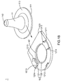
- FIG. 1B is a perspective view of a second embodiment of the present invention, showing a detachable probe cover for an ear thermometer having a protrudent ring.
- FIG. 2A is a perspective view of a measuring probe of the ear thermometer equipped with a combining mechanism of an annular structure according to the first or second embodiment of the present invention.
- FIG. 2B is a perspective view of a measuring probe of the ear thermometer equipped with a combining mechanism formed as protrudent members according to the second embodiment of the present invention.
- FIG. 3A is a sectional view of a detachable probe cover mounted on a measuring probe of an ear thermometer according the first or second embodiment of the present invention.
- FIG. 3B is a partially enlarged view of Part A of FIG. 3A for illustrating the detachable probe cover mounted on the measuring probe of the ear thermometer according the first or second embodiment of the present invention.
- FIG. 4 is an assembled view of the detachable probe cover according the first or second embodiment of the present invention.
- FIG. 1A Please refer to FIG. 1A for a first embodiment of the present invention for a detachable probe cover 1 , provided for an ear thermometer, is provided.
- the detachable probe cover 1 comprises a main body 11 , a base 12 , an open end 111 , a closed end 112 , a flange 113 , a base plate 121 , an opening 122 , and protrusions 41 .
- the detachable probe cover 1 is for being mounted onto a measuring probe 21 of the ear thermometer. Please proceed to FIG.
- a combining mechanism 211 is provided at a bottom of the measuring probe 21 of the ear thermometer that may be formed as an annular structure so that when the detachable probe cover 1 is mounted onto the measuring probe 21 of the ear thermometer, the combining mechanism 211 at the bottom of the measuring probe 21 can be inlaid between the opening 122 formed at the center of the base plate 121 and the protrusions 41 of the base 12 of the detachable probe cover 1 so as to achieve combination between the detachable probe cover 1 and the measuring probe 21 .
- the main body 11 is of a hollow structure and is integrally made of plastic.
- the main body 11 has the open end 111 and the closed end 112 opposite to the open end 111 while the hollow structure has a diameter gradually reducing from the open end 111 toward the closed end 112 so that the hollow structure is shaped as a short truncated cone.
- the main body 11 may be made of polyethylene (PE), polypropylene (PP), polycarbonate (PC), polystyene (PS), poly ethylene terephthalate (PET) or poly vinyl chloride (PVC) where infrared rays can be transmitted through.
- the closed end 112 is a film wherethrough the measuring probe 21 of the ear thermometer receives a radiation wave (i.e. an infrared region) emitted by a human body.
- the main body 11 has a thickness of plastic decreasing from the open end 111 toward the closed end 112 so that the closed end 112 is the thinnest portion of the detachable probe cover 1
- the flange 113 is radially extended outward from the open end 111 .
- the flange 113 may be a seamless integral or a sectioned flange with seams or intervals thereon, wherein the flange 113 formed as the seamless integral is most preferred.
- the base 12 comprises the base plate 121 and the opening 122 formed at a center of the base plate 121 .
- the opening 122 formed at the center of the base plate 121 is positionally corresponding to the open end 111 of the main body 11 .
- the base 12 is further provided with a pair of retaining recesses 1211 and an entrance 1213 is formed at one end of each said retaining recess 1211 .
- the retaining recesses 1211 are symmetrically settled so that the flange 113 is allowed to enter and be inlaid in the base 12 through the entrances 1213 . Furthermore, a distance between the entrances 1213 is smaller than a maximum diameter of the flange 113 of the main body 11 , so that the flange 113 of the main body 11 can be secured after entering the entrances 1213 . In addition, a distance between two rear ends 1214 of the retaining recesses 1211 is smaller than the distance between the entrances 1213 , so as to retain the flange 113 of the inlaid main body 11 from excessively moving.
- the rear ends 1214 of the retaining recesses 1211 may be such extended that the two retaining recesses 1211 are connected mutually (as shown in FIG. 4 ), so that when the flange 113 of the main body 11 is inlaid in the base 12 , the main body 11 is allowed to slightly shift with respect to the opening 122 .
- the detachable probe cover 1 when the detachable probe cover 1 is to be mounted onto the measuring probe 21 of the ear thermometer, since the main body 11 is allowed to slightly shift, the detachable probe cover 1 can be smoothly mounted onto the measuring probe 21 of the ear thermometer.
- the base plate 121 of the base 12 may be further provided with at least one block 1212 for additionally retaining the flange 113 of the main body 11 from excessively moving.
- the base 12 further comprises a guiding edge 123 for directionally guiding the detachable probe cover 1 when the detachable probe cover 1 is to be assembled or stacked.
- the retaining recesses 1211 and the base plate 121 may be integrally formed or be assembled mutually, wherein it is most preferred that the retaining recesses 1211 and the base plate 121 are integrally formed. Furthermore, the retaining recesses 1211 and the base plate 121 of the base 12 may be assembled mutually with a method selected from the group consisting of an adhesive fixing process and a heat-melting fixing process.
- a protrudent device 4 is provided on the base plate 121 of the base 12 and faces the opening 122 .
- the protrudent device 4 is at lest two said protrusions 41 and a diameter of the opening 122 formed at the center of the base plate 121 is smaller than a diameter of the open end 111 of the main body 11 so that when the detachable probe cover 1 is mounted onto the measuring probe 21 of the ear thermometer, the combining mechanism 211 at the measuring probe 21 of the ear thermometer can be further inlaid between the opening 122 and the protrusions 41 of the base 12 so as to achieve combination between the detachable probe cover 1 and the measuring probe 21 .
- the protrusions 41 may be positioned symmetrically on the base 12 or may be deposited on the base 12 with unequal distances therebetween, wherein it is most preferred that the protrusions 41 are positioned symmetrically on the base 12 . Now referring to FIGS.
- a guiding surface 411 is further provided on each said protrusion 41 and facing the base 12 while a retaining surface 412 is further provided on each said protrusion 41 and facing the main body 11 so that when the detachable probe cover 1 is mounted onto the measuring probe 21 of the ear thermometer along an assembling direction 3 , a first included angle ⁇ 1 included between the guiding surface 411 and the assembling direction 3 is smaller than a second angle ⁇ 2 included between the retaining surface 412 and the assembling direction 3 .
- the detachable probe cover 1 can be mounted onto the measuring probe 21 of the ear thermometer with enhanced smoothness and firmness, so as to achieve combination between the detachable probe cover 1 and the measuring probe 21 .
- a distance between the retaining surface 412 and the closed end 112 is smaller than that between the combining mechanism 211 and an end of the measuring probe 21 , after the detachable probe cover 1 is mounted onto the measuring probe 21 and when the combining mechanism 211 at the bottom of the measuring probe 21 of the ear thermometer abuts on the retaining surface 412 , the main body 11 can be expanded and deformed because the distance between the combining mechanism 211 and an end of the measuring probe 21 is greater than that between the retaining surface 412 and the closed end 112 . Consequently, the closed end 112 can present a smooth surface that allows infrared rays stably pierce therethrough in order to ensure that the ear thermometer obtains measuring results with less inaccuracy.
- the present invention further provides a second embodiment.
- a detachable probe cover 1 provided for an ear thermometer, is provided.
- the detachable probe cover 1 comprises a main body 11 , a base 12 , an open end 111 , a closed end 112 , a flange 113 , a base plate 121 , an opening 122 , and a protrudent ring 42 .
- a combining mechanism 211 may be formed as protrudent members or an annular shape, whereby a measuring probe 21 of an ear thermometer can be inlaid between the opening 122 formed at the center of the base plate 121 and the protrudent ring 42 of the base 12 of the detachable probe cover 1 so as to achieve combination between the detachable probe cover 1 and the measuring probe 21 .
- Other characteristics of the detachable probe cover 1 may be as those disclosed in the first embodiment.
- the present invention further provides a third embodiment related to a manufacturing method for the detachable probe cover 1 according to the first embodiment.
- the disclosed method comprises: (1) providing a main body 11 , which is integrally made of plastic and has at least one flange 113 extended radially from an open end 111 of the main body 11 ; and (2) providing a base 12 , which comprises a base plate 121 and an opening 122 formed at the center of the base plate 121 , wherein the opening 122 is positionally corresponding to the open end 111 of the main body 11 and the base 12 is formed with at least one entrance 1213 for allowing the flange 113 of the main body 11 to be inlaid in the base 12 .
- the combining mechanism 211 provided at a bottom of a measuring probe 21 of the ear thermometer is of an annular structure (referring to FIG. 2A ) whereby the combining mechanism 211 can retain the measuring probe 21 of the ear thermometer between the opening 122 formed at the center of the base plate 121 and protrusions 41 of the base 12 of the detachable probe cover 1 so as to achieve combination between the detachable probe cover 1 and the measuring probe 21 of the ear thermometer.
- Other characteristics of the detachable probe cover 1 may be as those disclosed in the first embodiment.
- the present invention further provides a fourth embodiment related to a manufacturing method for the detachable probe cover 1 according to the second embodiment.
- the disclosed method comprises: (1) providing a main body 11 , which is integrally made of plastic and has at least one flange 113 extended radially from an open end 111 of the main body 11 ; and (2) providing a base 12 , which comprises a base plate 121 and an opening 122 formed at the center of the base plate 121 , wherein the opening 122 is positionally corresponding to the open end 111 of the main body 11 and the base 12 is formed with at least one entrance 1213 for allowing the flange 113 of the main body 11 to be inlaid in the base 12 .
- a combining mechanism 211 provided at a bottom of a measuring probe of the ear thermometer is formed as protrudent members (referring to FIG. 2B ) or of an annular structure (referring to FIG. 2A ) whereby the measuring probe 21 of the ear thermometer can be inlaid between the opening 122 formed at the center of the base plate 121 and a protrudent ring 42 of the base 12 of the detachable probe cover 1 so as to achieve combination between the detachable probe cover 1 and the measuring probe 21 of the ear thermometer.
- Other characteristics of the detachable probe cover 1 may be as those disclosed in the first embodiment.
Abstract
This present invention discloses a detachable probe cover for an ear thermometer and a manufacturing method thereof. The detachable probe cover for the ear thermometer is for being mounted onto a measuring probe of the ear thermometer, wherein a combining mechanism is provided at a bottom of the measuring probe and the detachable probe cover comprises a main body of a hollow structure and a base, in which the main body has an open end and a closed end opposite to the open end, and the hollow structure has a diameter gradually reducing from the open end toward the closed end.
Description
1. Technical Field
The present invention relates to a probe cover for an ear thermometer and, more particularly, to a detachable probe cover for an ear thermometer.
2. Description of Related Art
In the known technical field, a cover for sheathing a temperature probe of an ear thermometer may be referred to the disclosure of some patents such as U.S. Pat. No. 5,088,834 and U.S. Pat. No. 6,022,140. The prior disclosure relates to a unitary probe cover that is equipped with a rim at a proximal portion thereof to couple a retention ears on the ear thermometer probe so as to fix the probe cover onto the ear thermometer probe. Further, a side wall of the probe cover is preferentially deformed in reaction to the ear thermometer probe straightening a surface of the cover. However, since the side wall is made of a material having limited elasticity, it can also provide limited effect on relaxing manufacturing tolerances. That is, the surface at a distal end portion of the cover can not be efficiently expanded, resulting in inaccurate measuring results of the ear thermometer. Furthermore, U.S. Pat. No. 5,163,418, U.S. Pat. No. 5,906,437, U.S. Pat. No. 6,371,639 and U.S. Pat. No. 6,647,284 all provide probe covers made of thin film. Such probe covers have some disadvantages, such as complex assembling process, inartistic appearance, wrinkled surfaces, and causing uncomfortableness to ears. To remedy the aforementioned defects of the conventional probe covers for ear thermometers, it is desired to improve the prior arts with a detachable probe cover, which can be finely adjusted when being mounted onto a probe of an ear thermometer and then has a portion corresponding to a measuring end of the probe smoothened so as to allow infrared rays stably pierce therethrough in order to ensure stableness and accuracy of measuring results of the ear thermometer.
In the attempt to remedy the imperfectness of the prior arts, the present invention provides a detachable probe cover for an ear thermometer that is primarily constructed from a main body of a hollow structure and a base, wherein the main body has an open end and a closed end opposite to the open end, and the hollow structure has a diameter gradually reducing from the open end toward the closed end.
Thus, it is one objective of the present invention to provide a detachable probe cover for an ear thermometer, in which the detachable probe cover can be automatically aligned so as to be easily mounted on and not easily take off a measuring probe of the ear thermometer.
It is another objective of the present invention to provide a detachable probe cover for an ear thermometer, in which when the detachable probe cover is mounted onto a measuring probe of the ear thermometer, the detachable probe cover is smoothened so as to facilitate more stable and more accurate measuring results of the ear thermometer.
It is another objective of the present invention to provide a manufacturing method for a detachable probe cover of an ear thermometer, in which the detachable probe cover can be automatically aligned so as to be easily mounted on and not easily take off a measuring probe of the ear thermometer.
It is another objective of the present invention to provide a manufacturing method for a detachable probe cover of an ear thermometer, in which when the detachable probe cover is mounted onto a measuring probe of the ear thermometer, the detachable probe cover is smoothened so as to facilitate more stable and more accurate measuring results of the ear thermometer.
The invention as well as a preferred mode of use, further objectives and advantages thereof, will best be understood by reference to the following detailed description of an illustrative embodiment when read in conjunction with the accompanying drawings, wherein:
While the present invention discloses a detachable probe cover for an ear thermometer, it is to be stated first of all that the detailed manufacturing or processing procedures of the ear thermometer have been familiar to people skilled in the art and need not be discussed at length herein. Meantime, while the accompanying drawings are provided for the purpose of illustration, it is to be understood that the drawings are directed to the characteristics of the present invention and need not to be made in scale.
Please refer to FIG. 1A for a first embodiment of the present invention for a detachable probe cover 1, provided for an ear thermometer, is provided. The detachable probe cover 1 comprises a main body 11, a base 12, an open end 111, a closed end 112, a flange 113, a base plate 121, an opening 122, and protrusions 41. Therein, the detachable probe cover 1 is for being mounted onto a measuring probe 21 of the ear thermometer. Please proceed to FIG. 2A , wherein a combining mechanism 211 is provided at a bottom of the measuring probe 21 of the ear thermometer that may be formed as an annular structure so that when the detachable probe cover 1 is mounted onto the measuring probe 21 of the ear thermometer, the combining mechanism 211 at the bottom of the measuring probe 21 can be inlaid between the opening 122 formed at the center of the base plate 121 and the protrusions 41 of the base 12 of the detachable probe cover 1 so as to achieve combination between the detachable probe cover 1 and the measuring probe 21.
The main body 11 is of a hollow structure and is integrally made of plastic. The main body 11 has the open end 111 and the closed end 112 opposite to the open end 111 while the hollow structure has a diameter gradually reducing from the open end 111 toward the closed end 112 so that the hollow structure is shaped as a short truncated cone. The main body 11 may be made of polyethylene (PE), polypropylene (PP), polycarbonate (PC), polystyene (PS), poly ethylene terephthalate (PET) or poly vinyl chloride (PVC) where infrared rays can be transmitted through. The closed end 112 is a film wherethrough the measuring probe 21 of the ear thermometer receives a radiation wave (i.e. an infrared region) emitted by a human body. The main body 11 has a thickness of plastic decreasing from the open end 111 toward the closed end 112 so that the closed end 112 is the thinnest portion of the detachable probe cover 1.
At least one of said flange 113 is radially extended outward from the open end 111. The flange 113 may be a seamless integral or a sectioned flange with seams or intervals thereon, wherein the flange 113 formed as the seamless integral is most preferred. The base 12 comprises the base plate 121 and the opening 122 formed at a center of the base plate 121. When the main body 11 is inlaid into the base 12, the opening 122 formed at the center of the base plate 121 is positionally corresponding to the open end 111 of the main body 11. Besides, the base 12 is further provided with a pair of retaining recesses 1211 and an entrance 1213 is formed at one end of each said retaining recess 1211. Therein, the retaining recesses 1211 are symmetrically settled so that the flange 113 is allowed to enter and be inlaid in the base 12 through the entrances 1213. Furthermore, a distance between the entrances 1213 is smaller than a maximum diameter of the flange 113 of the main body 11, so that the flange 113 of the main body 11 can be secured after entering the entrances 1213. In addition, a distance between two rear ends 1214 of the retaining recesses 1211 is smaller than the distance between the entrances 1213, so as to retain the flange 113 of the inlaid main body 11 from excessively moving. The rear ends 1214 of the retaining recesses 1211 may be such extended that the two retaining recesses 1211 are connected mutually (as shown in FIG. 4 ), so that when the flange 113 of the main body 11 is inlaid in the base 12, the main body 11 is allowed to slightly shift with respect to the opening 122. Thereby, when the detachable probe cover 1 is to be mounted onto the measuring probe 21 of the ear thermometer, since the main body 11 is allowed to slightly shift, the detachable probe cover 1 can be smoothly mounted onto the measuring probe 21 of the ear thermometer.
The base plate 121 of the base 12 may be further provided with at least one block 1212 for additionally retaining the flange 113 of the main body 11 from excessively moving. On the other hand, the base 12 further comprises a guiding edge 123 for directionally guiding the detachable probe cover 1 when the detachable probe cover 1 is to be assembled or stacked.
The retaining recesses 1211 and the base plate 121 may be integrally formed or be assembled mutually, wherein it is most preferred that the retaining recesses 1211 and the base plate 121 are integrally formed. Furthermore, the retaining recesses 1211 and the base plate 121 of the base 12 may be assembled mutually with a method selected from the group consisting of an adhesive fixing process and a heat-melting fixing process.
A protrudent device 4 is provided on the base plate 121 of the base 12 and faces the opening 122. The protrudent device 4 is at lest two said protrusions 41 and a diameter of the opening 122 formed at the center of the base plate 121 is smaller than a diameter of the open end 111 of the main body 11 so that when the detachable probe cover 1 is mounted onto the measuring probe 21 of the ear thermometer, the combining mechanism 211 at the measuring probe 21 of the ear thermometer can be further inlaid between the opening 122 and the protrusions 41 of the base 12 so as to achieve combination between the detachable probe cover 1 and the measuring probe 21. The protrusions 41 may be positioned symmetrically on the base 12 or may be deposited on the base 12 with unequal distances therebetween, wherein it is most preferred that the protrusions 41 are positioned symmetrically on the base 12. Now referring to FIGS. 3A and 3B , a guiding surface 411 is further provided on each said protrusion 41 and facing the base 12 while a retaining surface 412 is further provided on each said protrusion 41 and facing the main body 11 so that when the detachable probe cover 1 is mounted onto the measuring probe 21 of the ear thermometer along an assembling direction 3, a first included angle θ1 included between the guiding surface 411 and the assembling direction 3 is smaller than a second angle θ2 included between the retaining surface 412 and the assembling direction 3. Thereupon, the detachable probe cover 1 can be mounted onto the measuring probe 21 of the ear thermometer with enhanced smoothness and firmness, so as to achieve combination between the detachable probe cover 1 and the measuring probe 21. As in the detachable probe cover 1, a distance between the retaining surface 412 and the closed end 112 is smaller than that between the combining mechanism 211 and an end of the measuring probe 21, after the detachable probe cover 1 is mounted onto the measuring probe 21 and when the combining mechanism 211 at the bottom of the measuring probe 21 of the ear thermometer abuts on the retaining surface 412, the main body 11 can be expanded and deformed because the distance between the combining mechanism 211 and an end of the measuring probe 21 is greater than that between the retaining surface 412 and the closed end 112. Consequently, the closed end 112 can present a smooth surface that allows infrared rays stably pierce therethrough in order to ensure that the ear thermometer obtains measuring results with less inaccuracy.
The present invention further provides a second embodiment. Please refer to FIG. 1B through FIG. 4 for a detachable probe cover 1, provided for an ear thermometer, is provided. The detachable probe cover 1 comprises a main body 11, a base 12, an open end 111, a closed end 112, a flange 113, a base plate 121, an opening 122, and a protrudent ring 42. In such case, a combining mechanism 211 may be formed as protrudent members or an annular shape, whereby a measuring probe 21 of an ear thermometer can be inlaid between the opening 122 formed at the center of the base plate 121 and the protrudent ring 42 of the base 12 of the detachable probe cover 1 so as to achieve combination between the detachable probe cover 1 and the measuring probe 21. Other characteristics of the detachable probe cover 1 may be as those disclosed in the first embodiment.
The present invention further provides a third embodiment related to a manufacturing method for the detachable probe cover 1 according to the first embodiment. The disclosed method comprises: (1) providing a main body 11, which is integrally made of plastic and has at least one flange 113 extended radially from an open end 111 of the main body 11; and (2) providing a base 12, which comprises a base plate 121 and an opening 122 formed at the center of the base plate 121, wherein the opening 122 is positionally corresponding to the open end 111 of the main body 11 and the base 12 is formed with at least one entrance 1213 for allowing the flange 113 of the main body 11 to be inlaid in the base 12. Therein, the combining mechanism 211 provided at a bottom of a measuring probe 21 of the ear thermometer is of an annular structure (referring to FIG. 2A ) whereby the combining mechanism 211 can retain the measuring probe 21 of the ear thermometer between the opening 122 formed at the center of the base plate 121 and protrusions 41 of the base 12 of the detachable probe cover 1 so as to achieve combination between the detachable probe cover 1 and the measuring probe 21 of the ear thermometer. Other characteristics of the detachable probe cover 1 may be as those disclosed in the first embodiment.
The present invention further provides a fourth embodiment related to a manufacturing method for the detachable probe cover 1 according to the second embodiment. The disclosed method comprises: (1) providing a main body 11, which is integrally made of plastic and has at least one flange 113 extended radially from an open end 111 of the main body 11; and (2) providing a base 12, which comprises a base plate 121 and an opening 122 formed at the center of the base plate 121, wherein the opening 122 is positionally corresponding to the open end 111 of the main body 11 and the base 12 is formed with at least one entrance 1213 for allowing the flange 113 of the main body 11 to be inlaid in the base 12. Therein, a combining mechanism 211 provided at a bottom of a measuring probe of the ear thermometer is formed as protrudent members (referring to FIG. 2B ) or of an annular structure (referring to FIG. 2A ) whereby the measuring probe 21 of the ear thermometer can be inlaid between the opening 122 formed at the center of the base plate 121 and a protrudent ring 42 of the base 12 of the detachable probe cover 1 so as to achieve combination between the detachable probe cover 1 and the measuring probe 21 of the ear thermometer. Other characteristics of the detachable probe cover 1 may be as those disclosed in the first embodiment.
Although the particular embodiments of the invention have been described in detail for purposes of illustration, it will be understood by one of ordinary skill in the art that numerous variations will be possible to the disclosed embodiments without going outside the scope of the invention as disclosed in the claims.
Claims (7)
1. A detachable probe cover for an ear thermometer, which is to be mounted onto a measuring probe of the ear thermometer, wherein a combining mechanism is provided at a bottom of the measuring probe and the detachable probe cover comprises a main body of a hollow structure and a base, in which the main body has an open end and a closed end opposite to the open end, and the hollow structure has a diameter gradually reducing from the open end toward the closed end, which is characterized in:
the main body being integrally made of a plastic material and having at least one flange radially extended outward from the open end;
the base comprising a base plate and an opening formed at a center of the base plate, the opening being corresponding to the open end of the main body and the base plate having at least one entrance for allowing the flange to enter and being inlaid in the base through the entrance; and
a protrudent device being provided on the base plate of the base and faces the opening so that when the detachable probe cover is mounted onto the measuring probe of the ear thermometer, the combining mechanism at the measuring probe of the ear thermometer is further inlaid between the opening and the protrudent device of the base so as to achieve a combination between the detachable probe cover and the measuring probe.
2. The detachable probe cover of claim 1 , wherein the protrudent device is at least two protrusions or at least one protrudent ring.
3. The detachable probe cover of claim 2 , wherein the two protrusions are positioned symmetrically on the base or are deposited on the base with unequal distances threbetween.
4. The detachable probe cover of claim 1 , wherein a guiding surface is provided on the protrudent device and faces the base while a retaining surface is provided on the protrudent device and faces the main body, the combining mechanism of the ear thermometer abuts on the retaining surface, and the closed end is smoothened to allow infrared rays to be stably transmitted therethrough.
5. The detachable probe cover of claim 1 , wherein a diameter of the opening formed at the center of the base is smaller than a diameter of the open end of the main body, so that when the detachable probe cover is mounted onto the measuring probe of the ear thermometer, the combining mechanism of the ear thermometer is inlaid between the opening and the open end of the main body so as to achieve combination between the detachable probe cover and the measuring probe.
6. The detachable probe cover of claim 1 , wherein the base further comprises a guiding edge for directionally guiding the detachable probe cover when the detachable probe cover is to be assembled or stacked.
7. The detachable probe cover of claim 1 , wherein the main body is made of a material selected from the group consisting of polyethylene (PE), polypropylene (PP), polycarbonate (PC), polystyene (PS), poly ethylene terephthalate (PET) and poly vinyl chioride (PVC) that infrared rays is transmitted therethrough.
Priority Applications (1)
| Application Number | Priority Date | Filing Date | Title |
|---|---|---|---|
| US13/307,885 US8657491B2 (en) | 2007-11-09 | 2011-11-30 | Detachable probe cover for ear thermometer and manufacturing method thereof |
Applications Claiming Priority (3)
| Application Number | Priority Date | Filing Date | Title |
|---|---|---|---|
| TW096142339 | 2007-11-09 | ||
| TW096142339A TW200921063A (en) | 2007-11-09 | 2007-11-09 | Probe cover for ear thermometer and manufacturing method thereof |
| TW96142339A | 2007-11-09 |
Related Child Applications (1)
| Application Number | Title | Priority Date | Filing Date |
|---|---|---|---|
| US13/307,885 Continuation-In-Part US8657491B2 (en) | 2007-11-09 | 2011-11-30 | Detachable probe cover for ear thermometer and manufacturing method thereof |
Publications (2)
| Publication Number | Publication Date |
|---|---|
| US20090122835A1 US20090122835A1 (en) | 2009-05-14 |
| US8092082B2 true US8092082B2 (en) | 2012-01-10 |
Family
ID=40279032
Family Applications (1)
| Application Number | Title | Priority Date | Filing Date |
|---|---|---|---|
| US12/116,304 Expired - Fee Related US8092082B2 (en) | 2007-11-09 | 2008-05-07 | Detachable probe cover for ear thermometer and manufacturing method thereof |
Country Status (6)
| Country | Link |
|---|---|
| US (1) | US8092082B2 (en) |
| EP (1) | EP2060889B1 (en) |
| JP (1) | JP4665010B2 (en) |
| AT (1) | ATE540293T1 (en) |
| ES (1) | ES2379953T3 (en) |
| TW (1) | TW200921063A (en) |
Cited By (1)
| Publication number | Priority date | Publication date | Assignee | Title |
|---|---|---|---|---|
| USD787683S1 (en) * | 2009-04-09 | 2017-05-23 | Welch Allyn, Inc. | Cover for a probe |
Families Citing this family (3)
| Publication number | Priority date | Publication date | Assignee | Title |
|---|---|---|---|---|
| US8996096B2 (en) | 2011-07-19 | 2015-03-31 | Welch Allyn, Inc. | Systems and methods for determining patient temperature |
| EP3078951A1 (en) * | 2015-04-10 | 2016-10-12 | Silverlight AG | Device with a pir sensor |
| CN108714025A (en) * | 2018-04-10 | 2018-10-30 | 浙江智柔科技有限公司 | Physiological signal measuring apparatus sheath |
Citations (20)
| Publication number | Priority date | Publication date | Assignee | Title |
|---|---|---|---|---|
| US3987899A (en) * | 1975-04-25 | 1976-10-26 | Edwin L. Spangler, Jr. | Disposable thermometer cap and method of making same |
| US5088834A (en) | 1990-08-24 | 1992-02-18 | Thermoscan Inc. | Unitary probe cover |
| US5163418A (en) * | 1989-09-19 | 1992-11-17 | Thermoscan Inc. | Speculum cover |
| WO1995000067A1 (en) | 1993-06-18 | 1995-01-05 | Infra-Temp, Inc. | Electronic thermometer probe cover |
| US5906437A (en) | 1997-06-10 | 1999-05-25 | Oriental System Technology Inc. | Probe cover for a tympanic thermometer |
| US6022140A (en) | 1996-05-07 | 2000-02-08 | Braun Thermoscan | Enhanced protective lens cover for an infrared thermometer |
| JP2001078967A (en) | 1999-09-09 | 2001-03-27 | Kazuhito Sakano | Probe cover, ear type clinical thermometer probe attaching it, and attachment/detachment device |
| US6224256B1 (en) * | 1998-06-18 | 2001-05-01 | Harry Bala | Cover for medical probe |
| US6332090B1 (en) * | 1990-03-08 | 2001-12-18 | Alaris Medical Systems, Inc. | Thermally isolated probe for biomedical apparatus and method of communicating energy there through |
| US6371639B1 (en) | 2000-10-13 | 2002-04-16 | Radiant Innovation Inc. | Probe cover of a tympanic thermometer and method for manufacturing the same |
| EP1262753A1 (en) | 2001-06-01 | 2002-12-04 | Omron Corporation | Infrared clinical thermometer |
| JP2003190106A (en) | 2001-12-28 | 2003-07-08 | A & D Co Ltd | Probe cover for aural thermometer |
| US6619837B2 (en) * | 2001-05-17 | 2003-09-16 | Sherwood Services Ag | Probe cover with lubrication well |
| US6647284B1 (en) | 2002-09-16 | 2003-11-11 | Oriental System Technology Inc. | Probe cover of a tympanic thermometer and tympanic thermometer assembly |
| WO2004063687A1 (en) | 2003-01-06 | 2004-07-29 | Sherwood Services Ag | Tympanic thermometer with ejection mechanism |
| US20050027168A1 (en) | 2003-07-28 | 2005-02-03 | Welch Allyn, Inc. | Otoscopic tip element and related method of use |
| US20050027169A1 (en) | 2003-07-28 | 2005-02-03 | Welch Allyn, Inc. | Otoscope |
| DE10336436A1 (en) | 2003-08-08 | 2005-03-17 | Braun Gmbh | Disposable protective cap for infrared radiation thermometer's measurement tip has body, window transmissive to infrared radiation, electric circuit whose state can be altered that becomes changed when cap used or removed |
| US20110134962A1 (en) * | 2008-12-29 | 2011-06-09 | Jacob Fraden | Probe cover with matching feature for a medical thermometer |
| US20110160595A1 (en) * | 2009-12-30 | 2011-06-30 | Welch Allyn, Inc. | Medical instrument with probe, probe cover, and methods of using the same |
-
2007
- 2007-11-09 TW TW096142339A patent/TW200921063A/en unknown
-
2008
- 2008-04-01 JP JP2008094778A patent/JP4665010B2/en not_active Expired - Fee Related
- 2008-05-07 US US12/116,304 patent/US8092082B2/en not_active Expired - Fee Related
- 2008-07-03 EP EP08159569A patent/EP2060889B1/en not_active Not-in-force
- 2008-07-03 ES ES08159569T patent/ES2379953T3/en active Active
- 2008-07-03 AT AT08159569T patent/ATE540293T1/en active
Patent Citations (25)
| Publication number | Priority date | Publication date | Assignee | Title |
|---|---|---|---|---|
| US3987899A (en) * | 1975-04-25 | 1976-10-26 | Edwin L. Spangler, Jr. | Disposable thermometer cap and method of making same |
| US5163418A (en) * | 1989-09-19 | 1992-11-17 | Thermoscan Inc. | Speculum cover |
| US6332090B1 (en) * | 1990-03-08 | 2001-12-18 | Alaris Medical Systems, Inc. | Thermally isolated probe for biomedical apparatus and method of communicating energy there through |
| US5088834A (en) | 1990-08-24 | 1992-02-18 | Thermoscan Inc. | Unitary probe cover |
| WO1995000067A1 (en) | 1993-06-18 | 1995-01-05 | Infra-Temp, Inc. | Electronic thermometer probe cover |
| US6022140A (en) | 1996-05-07 | 2000-02-08 | Braun Thermoscan | Enhanced protective lens cover for an infrared thermometer |
| US5906437A (en) | 1997-06-10 | 1999-05-25 | Oriental System Technology Inc. | Probe cover for a tympanic thermometer |
| US6224256B1 (en) * | 1998-06-18 | 2001-05-01 | Harry Bala | Cover for medical probe |
| JP2001078967A (en) | 1999-09-09 | 2001-03-27 | Kazuhito Sakano | Probe cover, ear type clinical thermometer probe attaching it, and attachment/detachment device |
| US6371639B1 (en) | 2000-10-13 | 2002-04-16 | Radiant Innovation Inc. | Probe cover of a tympanic thermometer and method for manufacturing the same |
| US6619837B2 (en) * | 2001-05-17 | 2003-09-16 | Sherwood Services Ag | Probe cover with lubrication well |
| EP1262753A1 (en) | 2001-06-01 | 2002-12-04 | Omron Corporation | Infrared clinical thermometer |
| CN1389712A (en) | 2001-06-01 | 2003-01-08 | 欧姆龙株式会社 | Infrared thermometer |
| JP2003190106A (en) | 2001-12-28 | 2003-07-08 | A & D Co Ltd | Probe cover for aural thermometer |
| US6647284B1 (en) | 2002-09-16 | 2003-11-11 | Oriental System Technology Inc. | Probe cover of a tympanic thermometer and tympanic thermometer assembly |
| WO2004063687A1 (en) | 2003-01-06 | 2004-07-29 | Sherwood Services Ag | Tympanic thermometer with ejection mechanism |
| CN1720430A (en) | 2003-01-06 | 2006-01-11 | 舍伍德服务公开股份有限公司 | Tympanic thermometer with ejection mechanism |
| US20050027168A1 (en) | 2003-07-28 | 2005-02-03 | Welch Allyn, Inc. | Otoscopic tip element and related method of use |
| US20050027169A1 (en) | 2003-07-28 | 2005-02-03 | Welch Allyn, Inc. | Otoscope |
| JP2007500541A (en) | 2003-07-28 | 2007-01-18 | ウェルチ・アリン・インコーポレーテッド | Otoscope |
| CN1984599A (en) | 2003-07-28 | 2007-06-20 | 韦尔奇阿林公司 | Otoscopic tip element and related method of use |
| US20080123717A1 (en) * | 2003-07-28 | 2008-05-29 | Welch Allyn, Inc. | Disposable speculum for medical thermometer |
| DE10336436A1 (en) | 2003-08-08 | 2005-03-17 | Braun Gmbh | Disposable protective cap for infrared radiation thermometer's measurement tip has body, window transmissive to infrared radiation, electric circuit whose state can be altered that becomes changed when cap used or removed |
| US20110134962A1 (en) * | 2008-12-29 | 2011-06-09 | Jacob Fraden | Probe cover with matching feature for a medical thermometer |
| US20110160595A1 (en) * | 2009-12-30 | 2011-06-30 | Welch Allyn, Inc. | Medical instrument with probe, probe cover, and methods of using the same |
Cited By (4)
| Publication number | Priority date | Publication date | Assignee | Title |
|---|---|---|---|---|
| USD787683S1 (en) * | 2009-04-09 | 2017-05-23 | Welch Allyn, Inc. | Cover for a probe |
| USD852964S1 (en) | 2009-04-09 | 2019-07-02 | Welch Allyn, Inc | Cover for a probe or the like |
| USD923800S1 (en) | 2009-04-09 | 2021-06-29 | Welch Allyn, Inc. | Cover for a probe or the like |
| USD1015546S1 (en) | 2009-04-09 | 2024-02-20 | Welch Allyn, Inc. | Cover for a probe or the like |
Also Published As
| Publication number | Publication date |
|---|---|
| JP2009119237A (en) | 2009-06-04 |
| US20090122835A1 (en) | 2009-05-14 |
| ATE540293T1 (en) | 2012-01-15 |
| ES2379953T3 (en) | 2012-05-07 |
| JP4665010B2 (en) | 2011-04-06 |
| TW200921063A (en) | 2009-05-16 |
| EP2060889B1 (en) | 2012-01-04 |
| EP2060889A1 (en) | 2009-05-20 |
Similar Documents
| Publication | Publication Date | Title |
|---|---|---|
| US7585108B2 (en) | Probe cover for ear thermometer and manufacturing method thereof | |
| CN101612037B (en) | Tympanic thermometer probe cover with film support mechanism | |
| US8092082B2 (en) | Detachable probe cover for ear thermometer and manufacturing method thereof | |
| EP0995089B1 (en) | Ear type clinical thermometer | |
| US8657491B2 (en) | Detachable probe cover for ear thermometer and manufacturing method thereof | |
| US20080123717A1 (en) | Disposable speculum for medical thermometer | |
| EP1686636A4 (en) | Film-clad battery and method of producing film-clad battery | |
| US20060153278A1 (en) | Ear thermometer | |
| JP2004105733A (en) | Probe cover and assembly for eardrum thermometer | |
| US20030067957A1 (en) | Temperature detective structure of ear thermometer | |
| US6625288B1 (en) | Collapsing paraboloid dish and method | |
| US6371639B1 (en) | Probe cover of a tympanic thermometer and method for manufacturing the same | |
| JP3943208B2 (en) | Ear thermometer | |
| US7722250B2 (en) | Probe cover for ear thermometer | |
| EP1190668A4 (en) | Ear type clinical thermometer | |
| TWI734321B (en) | Holder and ear thermometer using the holder | |
| JP2004309567A (en) | Small-sized plastic lens | |
| JPH1137853A (en) | Probe cover of clinical thermometer | |
| US20030043884A1 (en) | Probe cover of ear thermometer | |
| JPH0856909A (en) | Clinical thermometer | |
| JP6868439B2 (en) | Concentrator for infrared sensor and its manufacturing method | |
| JP2003057359A (en) | Sensor | |
| JP2000227361A (en) | Infrared clinical thermometer | |
| JP4823094B2 (en) | Teeth body and substrate storage container | |
| JP3065287U (en) | Probe cover for eardrum thermometer |
Legal Events
| Date | Code | Title | Description |
|---|---|---|---|
| AS | Assignment |
Owner name: ACTHERM INC, TAIWAN Free format text: ASSIGNMENT OF ASSIGNORS INTEREST;ASSIGNOR:HSIEH, CHIH-WEI;REEL/FRAME:020911/0631 Effective date: 20080423 |
|
| REMI | Maintenance fee reminder mailed | ||
| LAPS | Lapse for failure to pay maintenance fees | ||
| STCH | Information on status: patent discontinuation |
Free format text: PATENT EXPIRED DUE TO NONPAYMENT OF MAINTENANCE FEES UNDER 37 CFR 1.362 |
|
| FP | Lapsed due to failure to pay maintenance fee |
Effective date: 20160110 |