US8095860B2 - Method for implementing stochastic equality nodes - Google Patents
Method for implementing stochastic equality nodes Download PDFInfo
- Publication number
- US8095860B2 US8095860B2 US12/153,749 US15374908A US8095860B2 US 8095860 B2 US8095860 B2 US 8095860B2 US 15374908 A US15374908 A US 15374908A US 8095860 B2 US8095860 B2 US 8095860B2
- Authority
- US
- United States
- Prior art keywords
- counter
- equality
- nodes
- node
- parity check
- Prior art date
- Legal status (The legal status is an assumption and is not a legal conclusion. Google has not performed a legal analysis and makes no representation as to the accuracy of the status listed.)
- Active, expires
Links
- 238000000034 method Methods 0.000 title claims abstract description 101
- 239000011159 matrix material Substances 0.000 claims abstract description 42
- 230000015654 memory Effects 0.000 claims abstract description 29
- 230000008569 process Effects 0.000 claims description 53
- 230000006870 function Effects 0.000 claims description 15
- 238000004891 communication Methods 0.000 claims description 8
- 230000007246 mechanism Effects 0.000 claims description 5
- 238000010586 diagram Methods 0.000 description 37
- 230000000875 corresponding effect Effects 0.000 description 22
- 238000012545 processing Methods 0.000 description 17
- 230000006978 adaptation Effects 0.000 description 13
- 230000000694 effects Effects 0.000 description 11
- 230000005540 biological transmission Effects 0.000 description 7
- 230000001172 regenerating effect Effects 0.000 description 6
- QERYCTSHXKAMIS-UHFFFAOYSA-M thiophene-2-carboxylate Chemical compound [O-]C(=O)C1=CC=CS1 QERYCTSHXKAMIS-UHFFFAOYSA-M 0.000 description 6
- 230000007704 transition Effects 0.000 description 6
- 238000012937 correction Methods 0.000 description 4
- 230000003044 adaptive effect Effects 0.000 description 3
- 230000008901 benefit Effects 0.000 description 3
- 238000009738 saturating Methods 0.000 description 3
- 238000001228 spectrum Methods 0.000 description 3
- 238000006243 chemical reaction Methods 0.000 description 2
- 230000001419 dependent effect Effects 0.000 description 2
- 238000001514 detection method Methods 0.000 description 2
- 230000035945 sensitivity Effects 0.000 description 2
- 238000004088 simulation Methods 0.000 description 2
- 230000003595 spectral effect Effects 0.000 description 2
- 238000012360 testing method Methods 0.000 description 2
- DSCFFEYYQKSRSV-KLJZZCKASA-N D-pinitol Chemical compound CO[C@@H]1[C@@H](O)[C@@H](O)[C@H](O)[C@H](O)[C@H]1O DSCFFEYYQKSRSV-KLJZZCKASA-N 0.000 description 1
- 230000001154 acute effect Effects 0.000 description 1
- 239000000654 additive Substances 0.000 description 1
- 230000000996 additive effect Effects 0.000 description 1
- 230000002411 adverse Effects 0.000 description 1
- 238000013459 approach Methods 0.000 description 1
- 238000013528 artificial neural network Methods 0.000 description 1
- 230000001174 ascending effect Effects 0.000 description 1
- 238000004422 calculation algorithm Methods 0.000 description 1
- 238000004364 calculation method Methods 0.000 description 1
- 230000008859 change Effects 0.000 description 1
- 230000002596 correlated effect Effects 0.000 description 1
- 238000013016 damping Methods 0.000 description 1
- 230000003247 decreasing effect Effects 0.000 description 1
- 238000013461 design Methods 0.000 description 1
- 238000011161 development Methods 0.000 description 1
- 230000008030 elimination Effects 0.000 description 1
- 238000003379 elimination reaction Methods 0.000 description 1
- 238000005516 engineering process Methods 0.000 description 1
- 238000007667 floating Methods 0.000 description 1
- 230000006872 improvement Effects 0.000 description 1
- 230000001788 irregular Effects 0.000 description 1
- 238000012804 iterative process Methods 0.000 description 1
- 238000012986 modification Methods 0.000 description 1
- 230000004048 modification Effects 0.000 description 1
- 230000010363 phase shift Effects 0.000 description 1
- 238000003672 processing method Methods 0.000 description 1
- 238000000275 quality assurance Methods 0.000 description 1
- 230000009467 reduction Effects 0.000 description 1
- 230000002441 reversible effect Effects 0.000 description 1
- 239000004065 semiconductor Substances 0.000 description 1
- 238000000638 solvent extraction Methods 0.000 description 1
- 238000009827 uniform distribution Methods 0.000 description 1
Images


Classifications
-
- H—ELECTRICITY
- H03—ELECTRONIC CIRCUITRY
- H03M—CODING; DECODING; CODE CONVERSION IN GENERAL
- H03M13/00—Coding, decoding or code conversion, for error detection or error correction; Coding theory basic assumptions; Coding bounds; Error probability evaluation methods; Channel models; Simulation or testing of codes
- H03M13/03—Error detection or forward error correction by redundancy in data representation, i.e. code words containing more digits than the source words
- H03M13/05—Error detection or forward error correction by redundancy in data representation, i.e. code words containing more digits than the source words using block codes, i.e. a predetermined number of check bits joined to a predetermined number of information bits
- H03M13/11—Error detection or forward error correction by redundancy in data representation, i.e. code words containing more digits than the source words using block codes, i.e. a predetermined number of check bits joined to a predetermined number of information bits using multiple parity bits
- H03M13/1102—Codes on graphs and decoding on graphs, e.g. low-density parity check [LDPC] codes
Definitions
- the instant invention relates to decoding of linear codes with parity check matrix and in particular to a decoding method and system for stochastic decoding of linear block codes.
- Data communication systems comprise three components: a transmitter; a transmission channel; and a receiver.
- Transmitted data become altered due to noise corruption and channel distortion.
- redundancy is intentionally introduced, and the receiver uses a decoder to make corrections.
- the use of error correction codes plays a fundamental role in achieving transmission accuracy, as well as in increasing spectrum efficiency.
- the transmitter encodes the data by adding parity check information and sends the encoded data through the transmission channel to the receiver.
- the receiver uses the decoder to decode the received data and to make corrections using the added parity check information.
- LDPC codes were first disclosed by Gallanger in the early 1960's, R. G. Gallager: “ Low Density Parity Check Codes ”, Cambridge, Mass.: MIT Press, 1963. LDPC codes are linear codes which have been found to be capable of error correcting performance close to the Shannon limit, as disclosed in D. J. C. MacKay and R. M. Neal: “ Near Shannon limit performance of low density parity check codes ”, Electron. Lett., vol. 32, no. 18, pp. 1645-1646.
- Reed-Solomon (RS) codes are non-binary linear block codes whose symbols are chosen from a Galois Field (GF). Good minimum distance of RS codes together with their non-binary nature result in good bit and burst error-correcting performance.
- RS codes are employed in a wide spectrum of applications including magnetic recording, media transmission and satellite communication. Methods for RS decoding are generally classified into Hard Decision Decoding (HDD) and Soft Decision Decoding (SDD) methods. In many existing applications algebraic HDD is used for RS decoding. However, algebraic HDD methods are not able to use “soft” information provided by maximum a posteriori or turbo decoders. Iterative decoding based on the SP process has been used in LDPC decoding.
- HDD Hard Decision Decoding
- SDD Soft Decision Decoding
- the SP process is then applied to the adapted parity check matrix. It was shown that this adaptation technique prevents the SP process from becoming locked at pseudo-equilibrium points and improves the convergence of the decoding process. Unfortunately, existing hardware implementations of RS decoders based on this process are highly complex and costly.
- Stochastic computation has been introduced in the 1960's as a method to design low precision digital circuits. Stochastic computation has been used, for example, in neural networks. The main feature of stochastic computation is that probabilities are represented as streams of digital bits which are manipulated using simple circuitry. Its simplicity has made it attractive for the implementation of error correcting decoders in which complexity and routing congestion are major problems, as disclosed, for example, in W. Gross, V. Gaudet, and A. Milner: “ Stochastic implementation of LDPC decoders ”, in the 39 th Asilomar Conf. on Signals, Systems, and Computers, Pacific Grove, Calif., November 2005.
- a major difficulty observed in stochastic decoding is the sensitivity to the level of switching activity—bit transition—for proper decoding operation, i.e. switching events become too rare and a group of nodes become locked into one state.
- a supemode is a special node which tabulates the incoming stochastic messages in histograms, estimates their probabilities and regenerates uncorrelated stochastic messages using random number generators.
- a logic circuitry comprising logic components forming equality nodes and parity check nodes, the equality nodes and the parity check nodes for performing an equality function and a parity check function in a stochastic decoding process, respectively, the equality nodes and the parity check nodes being electrically coupled such that they represent a factor graph of a parity check matrix of a linear code, the logic circuitry comprising a plurality of counter circuitries, each counter circuitry comprising a counter electrically coupled to a respective equality node, each counter circuitry for providing a chosen symbol in dependence upon the respective equality node being in a hold state.
- a method performed using a counter circuitry for each of a plurality of equality nodes of a logic circuitry for stochastic decoding comprising a counter
- the method performed in each counter circuitry comprising:
- a logic circuitry comprising logic components forming equality nodes and parity check nodes, the equality nodes and the parity check nodes for performing an equality function and a parity check function in a stochastic decoding process, respectively, the equality nodes and the parity check nodes being electrically coupled such that they represent a factor graph of a parity check matrix of a linear code, wherein each equality node of at least a subset of the equality nodes comprises:
- the internal memory interposed between the sub nodes such that the internal memory is connected to an output port of a respective sub node and to an input port of a following sub node, the internal memory for providing a chosen symbol if a respective sub node is in a hold state.
- FIG. 1 is a diagram illustrating a factor graph of a parity check matrix
- FIGS. 2 a and 2 b are diagrams illustrating processing of probability message in a SP process
- FIG. 3 is a diagram illustrating multiplication in stochastic computation
- FIG. 4 is a diagram illustrating division in stochastic computation
- FIG. 5 a is a simplified block diagram illustrating a parity check node in stochastic decoding
- FIG. 5 b is a simplified block diagram illustrating an equality node in stochastic decoding
- FIG. 6 is a simplified block diagram illustrating an example of latching in a factor graph
- FIG. 7 a is a simplified block diagram of a stochastic decoder according to an embodiment of the invention.
- FIG. 7 b is a simplified block diagram of a C element
- FIG. 8 is a simplified flow diagram of a method for stochastic decoding according to an embodiment of the invention for execution on the stochastic decoder shown in FIG. 7 a;
- FIGS. 9 a to 9 c are simplified block diagrams of a stochastic decoder according to an embodiment of the invention.
- FIG. 9 d is a simplified block diagram illustrating an edge memory for re-randomizing the stochastic stream according to an embodiment of the invention.
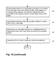
- FIG. 10 is a simplified flow diagram of a method for stochastic decoding according to an embodiment of the invention for execution on the stochastic decoder shown in FIGS. 9 a to 9 c;
- FIG. 11 is a simplified block diagram of a stochastic decoder according to an embodiment of the invention.
- FIG. 12 is a simplified flow diagram of a method for stochastic decoding according to an embodiment of the invention for execution on the stochastic decoder shown in FIG. 11 ;
- FIG. 13 is a diagram illustrating simulation results of the stochastic decoder according to an embodiment of the invention for a (7, 4) Hamming code;
- FIGS. 14 and 15 are diagrams illustrating simulation results of the stochastic decoder according to an embodiment of the invention for a (200, 100) LDPC code and for a (1024, 512) LDPC code, respectively;
- FIG. 16 is a simplified block diagram illustrating conversion of a channel probability into a corresponding probability message
- FIG. 17 is a simplified block diagram illustrating a degree-3 equality node with EM according to an embodiment of the invention.
- FIG. 18 is a simplified block diagram of a stochastic decoder according to an embodiment of the invention.
- FIGS. 19 a and 19 b are simplified block diagrams illustrating degree-7 equality nodes with 1M according to an embodiment of the invention.
- FIG. 19 c is a simplified block diagram illustrating a 2-bit IM according to an embodiment of the invention.
- FIG. 19 d is a simplified block diagram illustrating a degree-4 equality node with 1M according to an embodiment of the invention.
- FIGS. 20 a to 20 e are simplified block diagrams illustrating various counter circuitries for use as EMs or IMs according to embodiments of the invention.
- FIG. 21 is a schematic diagram illustrating an adapted parity-check matrix used in RS decoding.
- FIG. 22 is a simplified flow diagram of a method for stochastic RS decoding according to an embodiment of the invention.
- stochastic decoding method and decoder is described for decoding LDPC and RS codes for simplicity, it will become evident to those skilled in the art that the stochastic decoding method and decoder are not limited thereto but are also applicable for decoding of other linear block codes such as, for example, Bose-Chaudhuri-Hocquenghem (BCH) codes, and Turbo-Product codes, as well as for decoding of Convolutional LDPC codes.
- BCH Bose-Chaudhuri-Hocquenghem
- LDPC codes are a class of binary linear block codes in which a set of code words, x ⁇ C, spans the null space of a sparse parity check matrix H.
- Equation (1) is an example of a parity check matrix for a (12,3) LDPC code:
- FIG. 1 illustrates the factor graph of the parity check matrix H in equation (1).
- Nodes of a factor graph are separated into two distinct sets—equality nodes and check nodes. Each edge in the graph connects a node from the two sets.
- Check node c i is connected to equality node e j if and only if element h ij of the parity check matrix H is one.
- the number of edges connected to a node is called degree of the node.
- the SP process also known as message passing process, is an iterative process used for LDPC decoding.
- the SP process uses message passing over the edges of factor graphs. It has been shown that SP processes are capable of closely approximating the optimal decoding process for Additive White Gaussian Noise (AWGN) channels, i.e. the Maximum A posteriori Probability (MAP) process.
- AWGN Additive White Gaussian Noise
- MAP Maximum A posteriori Probability
- the decoding performance is dependent on the length of cycles in the factor graph, i.e. the longer the cycles the better the decoding performance. Short cycles such as the 4-cycle—indicated by dashed lines in FIG. 1 —correlate the messages and degrade the decoding performance.
- LLR Log-Likelihood Ratio
- BPSK Binary Phase Shift Keying
- the hardware implementation of the above SP process performs at each node of the factor graph complex computational operations on probabilities necessitating provision of a large number of hardware components. Furthermore, in the SP process probability messages are passed between the nodes resulting in routing congestion problems. As is evident, these problems are substantially increased for long LDPC codes.
- the probabilities are encoded using a Bernoulli sequence as a random sequence of ⁇ a i ⁇ digital bits. It is noted, that in stochastic computation used in decoding processes it is possible to encode the probabilities using deterministic or pseudo-random sequences. Each bit in the sequence is equal to logic ‘1’ with the probability to be encoded. A sequence of N bits with m bits equal to ‘1’ represents the probability of m/N. For example, a sequence of 10 bits with 6 bits equal to logic ‘1’ represents the probability of 0.6.
- the encoding scheme is not unique, i.e. different encoded stochastic sequences represent a same probability such as:
- FIG. 4 illustrates a JK flip-flop with input sequences of ⁇ a i ⁇ and ⁇ b i ⁇ representing the probabilities of P c and P b , respectively.
- the output bit c i is equal to logic ‘1’ with the probability of P c and is equal to logic ‘0’ with the probability of 1 ⁇ P c .
- Random output transition from logic ‘1’ to ‘0’ occurs with the probability of 1 ⁇ P c )P a and the reverse transition occurs with the probability of P c P b . From the equality of the expected occurrence of random transition in both directions follows:
- FIGS. 5 a and 5 b illustrate the corresponding hardware structures of the parity check node—equation (6)—and the equality node—equation (7), respectively.
- the stochastic computation also reduces the routing congestion problem, since only one bit—per direction—is used to represent an edge between a parity check node and an equality node. This implies that in a decoding round, the stochastic decoding proceeds by the equality nodes and the parity check nodes exchanging a bit—per direction—along each edge in the code factor graph.
- DCs Decoding Cycles
- a major difficulty observed in stochastic decoding is the sensitivity to the level of switching activity—bit transition—for proper decoding operation.
- the “latching” problem is described for stochastic decoding on graphs with cycles in C. Winstead, V. Gaudet, A. Rapley, and C. Schlegel: “ Stochastic iterative decoders ”, in Proc. of the IEEE Int. Symp. on Information Theory, September 2005, pp. 1116-1120.
- This problem refers to the situation where a cycle in the graph correlates messages in such a way that causes a group of nodes to lock into a state which is solely maintained by the correlated messages.
- the latching problem is particularly acute in LDPC decoders as taught in C.
- FIG. 6 illustrates how the lack of switching activity within a 4-cycle forces the equality nodes into a “hold” state for several DCs.
- the supemodes were used for trellis decoding of a (256,121) product Turbo code with the supernodes replacing all the equality nodes such that they were performing the conventional SP calculation according to equation (4) after a time step to calculate the probabilities of the new outgoing messages and to regenerate new stochastic messages.
- the channel LLRs for each block are scaled to a maximum value to ensure the same level of switching activity for each block.
- the introduction of supernodes diminishes the advantages of the stochastic computation by necessitating a highly complex hardware structure for implementing the supernodes.
- this technique is not applicable for the decoding of numerous LDPC and Hamming codes.
- the various embodiments of the stochastic decoder and their modes of operation are not limited to decoding of LDPC codes but are applicable for decoding numerous other classes of linear codes with parity check matrix such as, for example, Repeat-Accumulate codes, Turbo codes, BCH codes and Hamming codes, as well as for adaptive and non-adaptive decoding based on belief propagation methods.
- the various embodiments of the stochastic decoder and their modes of operation are described using a bitwise representation, but it will be apparent to those skilled in the art that they are also implementable using a symbol-wise representation, for example, symbols comprising two bits.
- symbols comprise a number of outcomes that is other than bit represented—for example decimal numbers. It is further noted, that the various embodiments of the stochastic decoder and their modes of operation, as well as combinations thereof, are not limited to decoding but are also implementable for detection.
- the stochastic decoder 100 comprises an input port 102 , processing circuitry 104 electrically coupled to the input port 102 , source circuitry 106 electrically coupled to the processing circuitry 104 , logic circuitry 108 electrically coupled to the processing circuitry, output circuitry 116 electrically coupled to the logic circuitry, and output port 120 electrically coupled to the output circuitry 116 .
- a set of encoded samples is received at the input port 102 for decoding—at 10 .
- the set of encoded samples is representative of a sequence of information bits and parity bits generated using a linear code with parity check matrix such as a LDPC code.
- the processing circuitry 104 determines a LLR of each of the encoded samples according to equation (2)—at 12 . As is evident, determining of the LLR is employed since it is generally used in decoding but the invention is not limited thereto.
- a scaling factor in dependence upon a noise power spectral density and a maximum value of the set of encoded samples is then determined—at 14 , and using the scaling factor the LLR of each of the encoded samples is scaled—at 16 .
- the scaled LLR, L i ′, for the i-th encoded sample, y, in the received set is calculated as:
- Y is a fixed maximum value of the received encoded samples
- ⁇ is a constant factor with 0 ⁇ .
- BER Bit Error Rate
- the scaled LLRs result in probabilities which introduce more switching activity and/or facilitate the convergence in the stochastic decoder. Because the scaling factor is proportional to the noise level, it ensures a substantially similar level of switching activity over different ranges of SNRs. Of course, one of skill in the art will readily arrive at different methods for implementing the NDS. Typically, scaling refers to downscaling though—contrary to common knowledge—there are situations where more switching activity or better convergence is introduced by upscaling.
- P init i e L i /(e L i +1).
- for each probability is then a corresponding probability message generated by encoding each probability as a sequence of digital bits.
- the sequence is a sequence of N ‘0’ bits and M ‘1’ bits with N and M depending on the probability to be encoded, as shown above for the probability of 0.6.
- the sequence is generated by the processor 104 in communication with the source circuitry 106 , with the source circuitry providing bit sets in one of a deterministic, pseudo-random, and random fashion and the processing circuitry using the bit sets for generating the sequence by concatenating the same and ensuring the correct number of ‘0’bits and ‘1’ bits in dependence upon the probability to be encoded.
- the source circuitry 106 comprises a Linear Feedback Shift Register (LFSR) for providing bit sets in a pseudo-random fashion.
- LFSR Linear Feedback Shift Register
- the logic circuitry 108 comprises logic components forming equality nodes 110 and parity check nodes 112 .
- each equality node 110 comprises two AND gates electrically coupled to respective J and K inputs of a JK flip-flop, as shown in FIG. 5 b , for performing the equality function—equation (7)—and each parity check node 112 comprises an XOR gate, as shown in FIG. 5 a , for performing the parity check function—equation (6).
- the equality nodes 110 and the parity check nodes 112 are electrically coupled such that they represent a factor graph of the parity check matrix, as shown, for example, in FIG. 1 .
- each probability message is received in a bitwise fashion at a respective equality node 110 and then passed—at 24 —in a bitwise fashion through the factor graph while for each received bit the equality function is performed at the equality nodes 110 and the parity check function is performed at the parity check nodes 112 .
- each equality node 110 After passage of a bit of each probability message through the factor graph at the end of a DC, each equality node 110 provides an output bit to, for example, a respective up/down counter 114 of the output circuitry 116 .
- the up/down counter 114 is decremented in case of a ‘0’ output bit and increased in case of a ‘1’ output bit.
- the sign bit of each of the up/down counters 114 indicates the “hard” decision, with a ‘0’ sign bit indicating a decoded ‘+1’ and a ‘1’ sign bit indicating a decoded ‘ ⁇ 1’, thus providing—at 26 —an estimated sequence of information bits in dependence upon the output bits provided by the equality nodes 110 .
- the above steps 20 to 24 are repeated until a stopping criterion is satisfied—at 28 .
- the steps 26 and 28 are performed using output processing circuitry 118 or, alternatively, processing circuitry 104 .
- the output stream provided by the equality nodes 110 is mapped to bits after each DC using, for example, up/down counters.
- a decrease in switching activity of the up/down counters is indicative of convergence of the decoding process, i.e. convergence to a binary “1” or a binary “0”. This enables substantially simpler and faster detection of convergence of the decoding process. Since the power consumption of the up/down counters is proportional to their switching activity convergence is easily detected by simply measuring the power consumption of the up/down counters.
- the JK flip-flop is replaced by a C element, shown in FIG. 7 b .
- Using the C element instead of the JK flip-flop enables operation of the equality nodes 110 and the parity check nodes 112 in an asynchronous fashion, i.e. independent from a clock signal. This provides the potential for substantially increasing the processing speed of the stochastic decoding process.
- an upscaling factor is determined other than in dependence upon a noise level.
- the upscaling factor is determined in an empirical fashion using a test signal.
- the stochastic equality node 110 has two states of operation:
- FIGS. 9 a and 10 a simplified block diagram of a second embodiment of a stochastic decoder 200 according to the invention, and a simplified flow diagram of a second embodiment of a method for stochastic decoding according to the invention for execution on the stochastic decoder 200 are shown, respectively.
- the stochastic decoder 200 comprises same main components as the stochastic decoder 100 illustrated in FIG. 7 a , except for second source circuitry interposed in the logic circuitry 208 at predetermined locations and in communication with the equality nodes 110 .
- the second source circuitry is interposed for providing a chosen bit if a respective equality node 110 —or a group of equality nodes 110 —is in a hold state, as explained above with respect to FIG.
- the second source circuitry comprises a plurality of memories 222 referred to as Edge Memories (EMs) with each EM being electrically coupled to a respective equality node 110 at each connection—or edge—of the factor graph.
- EMs Edge Memories
- each EM 222 comprises a shift register such as an M-bit shift register with M being an integer number between approximately 8 and 100.
- M being an integer number between approximately 8 and 100.
- Each EM 222 stores output bits of the respective equality node 110 when the respective equality node 110 is in a state other than a hold state and provides one of the stored bits when the respective equality node 110 is in a hold state.
- each EM 222 is placed at a connection connecting the respective equality node 110 with a corresponding parity check node 112 according to the factor graph, as shown in FIG. 9 b .
- each EM 222 is integrated into the respective equality node 110 .
- the bits are chosen in a deterministic fashion such as in a predetermined order: 1 st bit, 2 nd bit, . . . 1 st bit, last bit, 2 nd bit, 2 nd last bit; etc.
- the EM 222 is electrically coupled to a respective source 224 of one of a pseudo-random and random sequence of digital bits, for example, a LFSR for choosing a stored bit in a pseudo-random fashion.
- the EMs are grouped in subsets of EMs with each EM 222 of the subset being electrically coupled to a same source 224 of a pseudo-random sequence of digital bits associated therewith, as shown in FIG. 9 c .
- higher degree parity check nodes and equality nodes are easily converted to sub-graphs containing only degree three parity check nodes and equality nodes, respectively.
- the EMs such as, for example, shift-register based EMs and counter-based EMs—are optionally used for re-randomizing/de-correlating of the stochastic streams.
- operation of the EMs is as follows:
- a set of encoded samples is received at the input port 102 for decoding—at 30 .
- the set of encoded samples is representative of a sequence of information bits and parity bits generated using a linear code with parity check matrix such as a LDPC code.
- each of the encoded samples is then—at 32 —converted into a corresponding probability.
- for each probability is then a corresponding probability message generated by encoding each probability as a sequence of digital bits.
- each probability message is received in a bitwise fashion at a respective equality node 110 and then passed—at 38 —in a bitwise fashion through the factor graph while for each received bit the equality function is performed at the equality nodes 110 and the parity check function is performed at the parity check nodes 112 .
- a bit is chosen—at 40 —from previous output bits of the equality node 110 stored in a corresponding memory 222 .
- the previous output bits have been provided by the equality node 110 in a state other than a hold state.
- the memory 222 is updated when the equality node 110 in a state other than a hold state.
- an estimated sequence of information bits in dependence upon the output bits provided by the equality nodes 110 is determined—at 44 —and the steps 34 to 44 are repeated until a stopping criterion is satisfied.
- FIGS. 11 and 12 a simplified block diagram of an embodiment of a stochastic decoder 300 according to the invention, and a simplified flow diagram of an embodiment of a method for stochastic decoding according to the invention for execution on the stochastic decoder 300 are shown, respectively.
- the stochastic decoder 300 comprises same main components as the stochastic decoder 100 illustrated in FIG. 7 a , except for memory 306 replacing the source circuitry 106 .
- the memory 306 has stored a plurality of bit sets with each bit set comprising at least a bit. For example, the bit sets are stored in a form of a lookup table.
- the processing circuitry 104 retrieves selected bit sets from the memory 306 and generates for each probability a corresponding probability message by encoding each probability as a sequence of digital bits with the sequence of digital bits being determined as a sequence of N ‘0’ bits and M ‘1’ bits with N and M being integer numbers in dependence upon the probability.
- source circuitry 308 such as a LFSR, electrically coupled to the processing circuitry 104 is provided for enabling the processing circuitry 104 to select at least a portion of the bit sets in a pseudo-random fashion.
- a set of encoded samples is received at the input port 102 for decoding—at 50 .
- the set of encoded samples is representative of a sequence of information bits and parity bits generated using a binary linear code with parity check matrix such as a LDPC code.
- each of the encoded samples is then—at 52 —converted into a corresponding probability.
- for each probability is then a corresponding probability message generated by encoding each probability as a sequence of digital bits from the bit sets stored in the memory 306 .
- the sequence of digital bits is generated by expanding a bit set selected from the plurality of bit sets by adding bits to the selected bit set or by concatenating the selected bit set with other bit sets selected from the plurality of bit sets stored in the memory.
- the following decoding process is the same as shown in FIG. 8 —steps 22 to 28 .
- bit sets are selected in a deterministic fashion.
- a portion of the bit sets is selected in a pseudo-random fashion and the remaining bit sets are selected in a deterministic fashion to ensure the correct number of ‘0’bits and ‘1’ bits.
- a portion of the bit sets is selected in a pseudo-random fashion and the number of ‘0’bits and ‘1’ bits of the remaining bits is determined and the remaining bits are added accordingly.
- the bit sets are selected in a pseudo-random fashion, a sequence is generated and then examined if it contains the correct number of ‘0’bits and ‘1’ bits. This process is repeated until a sequence with the correct number of ‘0’bits and ‘1’ bits has been generated.
- the sequence is generated from the bit sets such that it comprises at least a predetermined number of bit transitions, with the number of bit transitions varying in dependence upon the probability.
- the generation of the sequence of digital bits using a lookup table enables substantially faster generation of the sequences than use of a pseudo-random or random source, substantially increasing decoding speed. Secondly, it enables deterministic generation of sequences which is used, for example, for testing purposes. Thirdly, it enables generation of sequences having at least a predetermined number of bit transitions, thus reducing the likelihood of equality nodes becoming locked in a fixed state.
- the probability messages are stored in the memory 306 and are provided in dependence upon a received encoded sample.
- a plurality of predetermined probability messages is stored in the memory 306 with each probability message having a respective address corresponding to an encoded sample.
- the probability message stored at the corresponding address is retrieved from the memory 306 .
- Storing the probability messages in the memory 306 obviates the conversion into probabilities—at 52 —and the generation of the probability messages—at 54 —is reduced to retrieving of the same from the memory 306 , thus processing speed is substantially enhanced.
- the predetermination of the probability messages includes the determination of a scaling factor.
- such a process is deterministic in nature and is therefore more easily evaluated for quality assurance purposes.
- the SNR is defined as E b /N 0 in dB, where E b denotes average energy per bit.
- a combination of the first and the second embodiment provides comparable BER performance for the (200,100) LDPC code and near-optimal performance for the (1024, 512) LDPC code.
- the DCs per block are substantially less than the maximum DCs.
- the average DCs for the (200,100) LDPC code is about 200 at the BER of 10 ⁇ 7 and for the (1024, 512) LDPC code it is about 6K at the BER of 10 ⁇ 5 .
- the DCs are not equivalent to the iterations in the SP process and due to the low hardware complexity of the stochastic decoder according to the invention, the clock rate is substantially higher than that in a fixed point SP process decoder.
- results for (i) decoding without NDS and EMs and, (ii) decoding with EMs but without NDS are also depicted in FIGS. 14 and 15 .
- the contribution of EMs is observed by comparing results for case (i) with (ii).
- the contribution of NDS at higher SNRs is easily observed by comparing the results of the combination of the first and second embodiment with case (ii).
- the above embodiments of the stochastic decoder according to embodiments of the invention and combinations thereof provide stochastic decoding on factor graph of state-of-the-art LDPC codes while substantially reducing the “latching” problem.
- the stochastic decoders according to embodiments of the invention achieve high performance at high-speed while enabling implementation using low-complexity hardware.
- the stochastic decoder according to the invention is implementable in one of a partially-parallel and a fully-parallel fashion on a single semiconductor chip or on a Field Programmable Gate Array (FPGA).
- FPGA Field Programmable Gate Array
- a fully-parallel implementation of a (1024, 512) stochastic LDPC decoder on a FPGA according to an embodiment of the invention is described hereinbelow.
- the NDS is applied according to equation (8).
- the (1024, 512) stochastic LDPC decoder is implemented using a 8-bit representation for the received channel probabilities.
- Each probability is encoded as a sequence of digital bits for generating a corresponding probability message, as shown in FIG. 16 .
- a comparator 500 compares the channel probability P with one of a random and pseudo-random sequence of digital bits R—with a uniform distribution—at each DC.
- the channel probability P is fixed during the decoding of a block, while the one of a random and pseudo-random sequence of digital bits R is updated for each DC.
- An output bit of the comparator 500 is equal to 1 if P>R and is equal to 0 otherwise. The output bit of the comparator 500 is then fed to an equality node 110 .
- each bit in the output stochastic stream is equal to 1 with a probability of P/2 8 .
- the decoder comprises one comparator 500 for each equality node 110 .
- R is generated using a randomization engine which is described below.
- the (1024, 512) stochastic LDPC decoder comprises one EM 222 per edge of each equality node 110 .
- the EMs 222 operate as M-bit shift registers with a—single—bit being selectable by address lines in each DC.
- the U signal is 1 and the equality node 110 applies the equality equation for determining the outgoing bit for the edge.
- the equality node updates the EM in a First-In-First-Out (FIFO) fashion.
- FIFO First-In-First-Out
- a bit is one of randomly and pseudo-randomly selected from the EM and used as the outgoing bit.
- the one of random and pseudo-random selection of a bit from an EM is done by generating one of a random and pseudo-random address for each EM in each DC using a randomization engine which is described below.
- a randomization engine which is described below.
- Modern FPGA architectures allow efficient implementation of the EMs by using small Look-Up Tables (LUTs) as Shift Register LUTs (SRLs) and accessing a single bit in the register.
- LUTs Look-Up Tables
- SRLs Shift Register LUTs
- a plurality of SRLs are cascaded to form shift registers of larger size.
- a 64-bit EM is implemented by cascading four 4-input LUTs. Each 4-input LUT forms a 16-bit shift register with a single output accessed by the LUT's address line.
- Such a 64-bit EM occupies only 2 slices of the Xilinx Virtex-4 FPGA.
- each equality node 110 is passed to an up/down counter 114 at the end of each DC, i.e. the (1024, 512) stochastic LDPC decoder comprises one counter 114 for each equality node 110 .
- the (1024, 512) stochastic LDPC decoder comprises one counter 114 for each equality node 110 .
- 6-bit signed saturation up/down counters counting from ⁇ 31 to 31—are used.
- the saturation up/down counters is incremented in case of receiving 1 and decremented in case of 0. It stops decrementing/incrementing when it reaches its minimum/maximum limits.
- the sign of the counter indicates the hard-decision at each DC.
- the randomization engine is used for generating one of random and pseudo-random probabilities for the comparators 500 as well as for generating one of random and pseudo-random addresses for the EMs.
- the random or pseudo-random numbers are shared at two levels without significant loss in decoder BER performance: (i) bits in random or pseudo-random numbers generated for the comparators are used for selecting addresses of the EMs and, (ii) different groups of EMs share the same randomly or pseudo-randomly selected address.
- the randomization engine comprises ten 16-bit Linear Feedback Shift Registers (LFSRs) with each LFSR being associated with a prime polynomial. Each bit in an output random or pseudo-random number is generated by performing an XOR function on a different bit of the ten LFSRs.
- the randomization engine generates 32 8-bit random or pseudo-random numbers in each DC for the entire decoder.
- FIG. 18 a simplified block diagram of an embodiment of a stochastic decoder 400 is shown.
- a set of encoded samples is received at the input port 402 .
- the signal data are then digitally processed.
- the decoder 400 comprises a storage medium 406 having stored therein executable commands for execution on the processor 404 for performing the stochastic decoding corresponding to one of the above processing methods.
- the processor 404 comprises electronic circuitry designed for performing at least a portion of the signal processing in a hardware implemented fashion.
- the decoder 400 comprises a plurality of processors for parallel execution of the stochastic decoding process.
- the system 400 further comprises an output port 408 for providing the estimated sequence ⁇ circumflex over (x) ⁇ .
- the decoder 400 comprises at least a memory 410 for storing at least one of the output bits, bit sets, and probability messages.
- the decoder 400 comprises a source circuitry 412 for providing digital bits in one of a pseudo-random and random fashion.
- the factor graphs of numerous error correcting codes such as, for example, some LDPC codes, RS codes, BCH codes, and Turbo-Product codes comprise high-degree equality nodes.
- a high-degree equality node is likely in a hold state.
- EMs an outgoing bit is selected from the EM when the equality node is in a hold state.
- use of the EM repeats previous output bits and results in less switching activity or poorer convergence.
- a high-degree equality node refers to its previous output bits substantially more often than a low-degree equality node.
- high-degree equality nodes are partitioned into a plurality of lower-degree equality “sub-nodes”—for example, degree-3 or degree-4 sub-nodes—with each lower-degree sub-node having an Internal Memory (IM) placed at its output port when output port is electrically coupled to an input port of a following sub-node.
- IM Internal Memory
- FIGS. 19 a and 19 b simplified block diagrams of a 7-degree equality node 110 according to an embodiment of the invention are shown. There are various possibilities for partitioning a high-degree equality node. For example, the 7-degree equality node is partitioned into 5 degree-3 sub-nodes 110 A to 1110 E, shown in FIG.
- IMs 111 A to 111 D are placed at a respective output port of the first four degree-3 sub-nodes 110 A to 110 D in FIG. 19 a
- 2 IMs 111 A and 111 B are placed at a respective output port of the first two degree-4 sub-nodes 110 A and 110 B in FIG. 19 a .
- the operation of the IMs is similar to the one of the EMs.
- the EM is placed at the output edge electrically coupled to an equality node and is used to provide an output bit for the entire equality node, while the IM is used to provide an output bit for only a sub-node within the equality node.
- the operation of a sub-node is then as follows:
- FIG. 19 c An example of an IM is shown in FIG. 19 c illustrating in a simplified block diagram a 2-bit IM based on a 2-bit shift register.
- the control signal C When the sub-node is in the regular state the control signal C is 1. In the regular state the bit i is calculated by the equality sub-node and provided as output bit y.
- a sub-node structure is determined based on an optimized BER performance of the decoder for a given code and size.
- a bit is selected from the IM using other methods such as, for example, round-robin.
- the IMs are employed for use in lower-degree equality nodes in order to improve the BER performance.
- a degree-4 equality node is partitioned into two degree-3 equality sub-nodes 110 A and 110 B having one IM 111 A placed at the output port of the first equality sub-node 110 A, as shown in FIG. 19 d.
- counter circuitries are employed to perform the function of the EMs and IMs, i.e. re-randomization and de-correlation of the probability messages within the factor graph.
- the counter is incremented by a step-size SI when the output bit of the corresponding equality node or equality sub-node is 1, and is decremented by a step-size SD when the output bit is 0, or vice versa.
- the counter is, for example, implemented as a saturation up/down counter which stops incrementing when it reaches a maximum limit C_MAX and stops decrementing when it reaches a minimum limit C_MIN.
- the output bit of the counter circuitry is determined according to the content of the counter at a DC.
- the counter circuitry 700 shown in FIG. 20 a comprises a counter 702 electrically coupled to a comparator 704 and a feedback line to the counter electrically coupled to node 706 , which is interposed between the counter 702 and the comparator 704 , and comprises a mixer 708 .
- the operation of the counter circuitry is then as follows:
- the counter circuitry 720 shown in FIG. 20 b comprises a counter 722 electrically coupled to a comparator 724 and a feedback line to the counter electrically coupled to node 726 at the output port of the comparator 724 .
- the operation of the counter circuitry 720 is the same as the one of the counter circuitry 700 shown in FIG. 20 a.
- the counter circuitry 730 shown in FIG. 20 c is similar to the counter circuitry 700 , shown in FIG. 20 a .
- Each of the two counters 732 A, 732 B comprises a feedback line electrically coupled to nodes 736 A and 736 B, with a mixer 738 A, 738 B, respectively.
- the output ports of the counters 732 A and 732 B are electrically coupled to the K input port of the comparator 734 via sum unit 739 .
- the operation of the counter circuitry 730 is the same as the one of the counter circuitry 700 , shown in FIG. 20 a.
- the counter circuitry 740 shown in FIG. 20 d is similar to the counter circuitry 710 , shown in FIG. 20 b .
- Each of the two counters 742 A, 742 B comprises a feedback line electrically coupled to node 746 at the output port of the comparator 744 .
- the output ports of the counters 742 A and 742 B are electrically coupled to the K input port of the comparator 744 via sum unit 749 .
- the operation of the counter circuitry 740 is the same as the one of the counter circuitry 710 , shown in FIG. 20 b.
- the counter circuitry 750 shown in FIG. 20 e is a combination of the counter circuitries 700 and 710 , shown in FIGS. 20 a and 20 b , respectively, comprising two feedback lines.
- the first feedback line to up/down counter 752 is electrically coupled to node 756 , which is interposed between the counter 752 and comparator 744 , and comprises a mixer 758 .
- the second feedback line to the counter 752 is electrically coupled to node 759 at the output port of the comparator 754 .
- step-sizes are changed during the decoding operation, as well as switch feedback lines ON/OFF or to switch feedback lines, for example, from negative feedback—output bit—to positive feedback—content using a switching mechanism disposed, for example, in the nodes 706 , 726 , 756 , and 759 .
- different counter circuitries are used for different nodes in the factor graph, as well as different counter configurations—for example, different size, different C_MAX and C_MIN, different SI and SD.
- Reed-Solomon (RS) codes are non-binary linear block codes whose symbols are chosen from a Galois Field (GF). Good minimum distance of RS codes together with their non-binary nature result in good bit and burst error-correcting performance.
- RS codes are employed in a wide spectrum of applications including magnetic recording, media transmission and satellite communication.
- the stochastic decoding method and decoder disclosed above is extended for decoding RS codes by incorporating the stochastic decoding with its bit-serial nature into a reliability-based parity check matrix adaptation technique used for iterative Soft-Input Soft-Output (SISO) RS decoding.
- SISO Soft-Input Soft-Output
- the stochastic decoding method and decoder disclosed above is extendable to non-adaptive RS decoding techniques such as RS decoding based on redundant factor graphs. While the stochastic decoding method and decoder is described for decoding an RS code for simplicity, it will become evident to those skilled in the art that the stochastic decoding method and decoder is not limited thereto but also applicable for decoding other linear block codes such as, for example, Golay codes and BCH codes.
- the parity check matrix of an (n, k) RS code over GF (2 m ) is represented by:
- the parity check matrix H is expanded to its binary representation, H b , by substituting each codeword in the GF (2 m ) with its equivalent binary representation.
- the binary parity check matrix H b is usually dense, the SP process is not directly applicable to H b . Therefore, at each iteration step of RS decoding two steps are performed:
- LLRs are sorted based on their absolute value in an ascending fashion and ordering indices are stored.
- L i l (l) ⁇ L i l (l) , . . . , L i N (l) ⁇ be the sorted list of LLRs and ⁇ i l , . . . , i N ⁇ be the stored indices.
- the first LLR, L i l (l) corresponds to the least reliable bit—the i l -th bit in the block—and the last LLR, L i N (l) , corresponds to the most reliable bit—i N -th bit in the block.
- the systemization is performed using, for example, the Gaussian elimination method. Since the binary parity check matrix is of full-rank, at least n ⁇ k columns are systemized to be of unity weight.
- FIG. 21 shows the form of an adapted parity check matrix which is decomposed into dense parts and low-density parts.
- the SP process is applied on the sorted LLRs, L (l) , based on the adapted parity check matrix, H b (l) , to generate the extrinsic LLRs, L ext (l) .
- the process returns to the adaptation step unless it has been executed for a fixed maximum number of iterations, l max , or all the parity checks are satisfied.
- an Incorporated Hard-Decision (IHD) step is performed at the end of each iteration by hard decisions on LLRs produced by the SP process. At the end of the decoding process, the most likely codeword is selected. This variance improves the convergence as well as the performance of the iterative RS decoder.
- the stochastic RS decoding method and decoder is designed to provide soft-output information.
- up/down counters are used with each counter being assigned to one equality node.
- a counter is incremented if the corresponding equality node output bit is “1”, unless the counter has reached its maximum limit (+U).
- the equality node output bit is “0” the counter is decremented, unless it has reached its minimum limit ( ⁇ U).
- the contents of the saturating counters are used for the IHD method.
- a hard decision is applied to V, which is similar to the above usage of up/down counters where the sign-bit of the counter determines the hard-decision.
- a “0” sign-bit indicates a negative value or a ⁇ 1 decision
- a “1” sign-bit indicates a positive value or a +1 decision.
- the expansion of the parity check matrix of a RS code to its binary representation results in a dense matrix, H b .
- the corresponding factor graph has equality and parity check nodes with degrees d e and d c substantially higher than the degrees of nodes in LDPC codes.
- the equivalent factor graph for a (63, 55) RS code comprises 378 equality nodes and 48 parity check nodes over GF (2 6 ).
- the maximum degree of the equality nodes and the parity check nodes is 34 and 184, respectively, and approximately 77% of the equality nodes have a degree d e ⁇ 20.
- the high-degree equality nodes are partitioned into a plurality of degree-3 equality sub-nodes.
- a partitioned high-degree equality node is less likely to be in a hold state, because by having stochastic input bits which are either mostly “0”—or “1”—the likelihood for the degree-3 exit sub-node is substantially less. Therefore, the entire node is less likely to be in a hold state.
- Employment of EMs and/or IMs, as described above, in factor graphs of RS codes substantially improves convergence and, therefore, decoding performance.
- a simplified flow diagram of a method for stochastic RS decoding according to an embodiment of the invention is shown.
- a binary parity check matrix, H b , and channel LLRs are received— 70 .
- the reliability based parity check matrix adaptation is performed to obtain H b (l) .
- the LLRs are scaled using NDS according to equation (8)—74—and then transformed into the probability domain— 76 .
- the probabilities are then converted into corresponding sequences of digital bits— 78 .
- Stochastic decoding is then applied to the sequences of digital bits by equality nodes and parity check nodes exchanging bits for a predetermined number of DCs— 80 .
- the extrinsic LLRs, L ext (l) are calculated according to equation (11)—82.
- L ext (l) is then used to update the LLRs according to equation (10)-84.
- IHD is optionally applied to the contents of the up/down counters.
- the decoding process then returns to the adaptation step 72 unless the decoding process has been executed for a predetermined number of iterations, l max , or all the parity checks are satisfied— 86 .
- the method for stochastic RS decoding according to the invention is performed using one of the stochastic decoders disclosed above with respect to the LDPC decoding. It is noted that due to the high-density of the binary parity check matrix H b , the correlation between stochastic messages within the factor graph are substantially higher than the correlation within the factor graph of a LDPC code of similar length. Therefore, in stochastic RS decoding EMs capable of storing a larger number of output bits are employed to alleviate latching. Of course, IMs and counter circuitries are optionally employed.
Abstract
Description
-
- receiving an output symbol from the respective equality node when the same is in a regular state;
- one of incrementing and decrementing content of the counter in dependence upon the received output symbol; and,
providing an output symbol in dependence upon the content when the respective equality node is in a hold state.
LDPC codes are effectively represented using a bipartite graph called a factor graph. Factor graphs provide a complete representation of the code, as well as help to describe the decoding process.
where σ2 is the variance of the AWGN and, xiε{−1,+1} and yiεR denote the i-th sample of the transmitted and received block, respectively. For example, let Pi→jε[0,i] be a probability message from equality node ei to check node cj (j=1, . . . , m), and Qj→lε[0,1] be a probability message from check node cj to equality node ei. Also, let {ei,el,em} be a set of equality nodes connected to a dc=3 check node cj, and {cj,cr,cs} be a set of check nodes connected to a de=3 equality node ei. It is noted, that this is without loss of generality, since it is possible to convert higher degree nodes to sub graphs containing only degree three nodes. Message passing steps in the SP process are then described as follows.
-
- I) For equality node ei, convert Li to an initialization probability as Pint i=eL
i /(eLi +1). - II) The equality node ei sends Pi→j=Pint i to check node cj.
- III) The check node cj determines Qj→i and sends it to the equality node ei, as shown in
FIG. 2 a, with Qj→i being determined as:
Q j→i =P l→j(1−P m→j)+P m→j(1−P l→j). (3) - IV) The equality node ei determines Pi→j and sends it to the check node cj, as shown in
FIG. 2 b, with Pi→j being determined as:
- I) For equality node ei, convert Li to an initialization probability as Pint i=eL
-
- V) Return to step III.
- VI) Stop the iteration once the estimated code word, {circumflex over (x)}, satisfies the criterion H{circumflex over (x)}=0, or after a predetermined number of iterations has been completed.
The stochastic representation of probabilities enables manipulation of the same using hardware of low complexity. Stochastic multiplication and stochastic division are the two operations used for implementing the decoding process.
The operation of equation (5) is an approximation to Pa/Pb, if Pa<<Pb 2.
P c =P a(1−P b)+P b(1−P a) (6)
The equality function in a de=3 equality node for inputs Pa and Pb is determined as
where N0=2σ2 is the double-sided noise power spectral density, Y is a fixed maximum value of the received encoded samples and, α is a constant factor with 0<α. For example, for BPSK transmission of LDPC codes values of Y=6 and α≅3 provided high performance—Bit Error Rate (BER) performance. As shown above, in Noise-Dependent Scaling (NDS), the received channel LLRs are scaled by a scaling factor proportional to the operating SNR. The scaled LLRs result in probabilities which introduce more switching activity and/or facilitate the convergence in the stochastic decoder. Because the scaling factor is proportional to the noise level, it ensures a substantially similar level of switching activity over different ranges of SNRs. Of course, one of skill in the art will readily arrive at different methods for implementing the NDS. Typically, scaling refers to downscaling though—contrary to common knowledge—there are situations where more switching activity or better convergence is introduced by upscaling.
-
- 1) regular state—when input bits of the
equality node 110 are equal; and, - 2) hold state—when input bits of the
equality node 110 are NOT equal.
In the regular state the output bit of theequality node 110 is determined in dependence upon the input bits of theequality node 110. When theequality node 110 is in a hold state, a bit is chosen and provided as output bit of theequality node 110 to de-correlate the stochastic messages, thus reducing the likelihood of theequality nodes 110 getting locked in the hold state. Optionally, memory—such as, for example, registers, shift registers, counters, up/down counters, saturation counters, look-up tables, and combinations thereof—is assigned to theequality node 110 such that one of its previous output bits are chosen as the output bit when in a hold state. The assigned memory is updated only by bits which are produced in the regular state, referred to as “regenerative bits”. Regenerative bits stored in the assigned memory are useful for determining statistics of stochastic streams in the decoder/detector and for producing the output bit in a hold state.
- 1) regular state—when input bits of the
- 1) in every DC the EMs are updated with any bit received from the edge; and,
- 2) In every DC the output bit of an EM is chosen or generated pseudo-randomly or randomly from its content.
In other words, the EMs gather the incoming bits—any incoming bits or only regenerative bits—from the edge and only re-randomize them. The EMs for re-randomizing the stochastic stream are, optionally, placed at any location on the edges of the factor graph. For example, the EMs are electrically coupled to incoming edges of theequality nodes 110 as shown inFIG. 9 d.
- 1) When all input bits of the sub-node are equal, the sub-node is in the regular state, using the equality operation on the input bits to calculate the output bit. The IM is updated with the new output bit, for example, in a FIFO fashion.
- 2) When the input bits are not equal, the equality sub-node is in the hold state. In this case a bit is randomly or pseudo-randomly selected from the previous output bits stored in the IM and provided as the new output bit. The IM is not updated in the hold state.
- 1) When the equality node or sub-node is in the regular state a regenerative bit x is received at the
counter 702 and the content of the counter is updated providing Ci+1 as:
C t+1 =C t +SI+AC t, when x=1; and,
C t+1 =C t −SD+AC t, when x=0; and,
wherein A is an address provided to themixer 708. - 2) When the equality node or sub-node is in the hold state the content Ct is provided to the K input port of the
comparator 704 and compared with a random or pseudo-random sequence of digital bits R. The output bit y is then determined in the comparator as:
y=0, when R≧K; and
y=1, when R<K.
C t+1 =C t +SI+SFI, when x=y=1;
C t+1 =C t +SI−SFD, when x=1,y=0;
C t+l =C t −SD+SFI, when x 0, y=1; and,
C t+1 =C t −SD−SFD, when x=y=0,
wherein SFI is the feedback line step-size to increment the
C t+1 =C t +SI+AC t +SFI, when x=y=1;
C t+1 =C t +SI+AC t −SFD, when x=1,y=0;
C t+1 =C t −SD+AC t +SFI, when x=0,y=1; and,
C t+1 =C t −SD+AC t −SFD, when x=y=0.
In the hold state of the equality node or sub-node the operation of the
where β is the primitive element in GF (2m) and dmin=n−
- 1) reliability-based adaptation of the binary parity check matrix Hb; and,
- 2) generation of extrinsic information using the SP process.
L (l+1) =L (l) +λ×L ext (l), (10)
where 0<λ<1 is a damping coefficient. The process returns to the adaptation step unless it has been executed for a fixed maximum number of iterations, lmax, or all the parity checks are satisfied. Optionally, an Incorporated Hard-Decision (IHD) step is performed at the end of each iteration by hard decisions on LLRs produced by the SP process. At the end of the decoding process, the most likely codeword is selected. This variance improves the convergence as well as the performance of the iterative RS decoder.
where In( . . . ) indicates the natural logarithm operation.
Claims (20)
Priority Applications (1)
| Application Number | Priority Date | Filing Date | Title |
|---|---|---|---|
| US12/153,749 US8095860B2 (en) | 2007-05-23 | 2008-05-23 | Method for implementing stochastic equality nodes |
Applications Claiming Priority (3)
| Application Number | Priority Date | Filing Date | Title |
|---|---|---|---|
| US92463207P | 2007-05-23 | 2007-05-23 | |
| US93584807P | 2007-09-04 | 2007-09-04 | |
| US12/153,749 US8095860B2 (en) | 2007-05-23 | 2008-05-23 | Method for implementing stochastic equality nodes |
Publications (2)
| Publication Number | Publication Date |
|---|---|
| US20080294970A1 US20080294970A1 (en) | 2008-11-27 |
| US8095860B2 true US8095860B2 (en) | 2012-01-10 |
Family
ID=40031364
Family Applications (1)
| Application Number | Title | Priority Date | Filing Date |
|---|---|---|---|
| US12/153,749 Active 2030-10-08 US8095860B2 (en) | 2007-05-23 | 2008-05-23 | Method for implementing stochastic equality nodes |
Country Status (2)
| Country | Link |
|---|---|
| US (1) | US8095860B2 (en) |
| WO (1) | WO2008141453A1 (en) |
Cited By (3)
| Publication number | Priority date | Publication date | Assignee | Title |
|---|---|---|---|---|
| US20100074381A1 (en) * | 2008-09-25 | 2010-03-25 | The Royal Institution For The Advancement Of Learning/ Mcgill University | Methods and systems for improving iterative signal processing |
| US20140250041A1 (en) * | 2010-02-22 | 2014-09-04 | Analog Devices, Inc. | Distributed factor graph system |
| US9100153B2 (en) | 2008-09-25 | 2015-08-04 | The Royal Institution For The Advancement Of Learning/Mcgill University | Methods and systems for improving iterative signal processing |
Families Citing this family (30)
| Publication number | Priority date | Publication date | Assignee | Title |
|---|---|---|---|---|
| US8099645B2 (en) * | 2008-04-11 | 2012-01-17 | Nec Laboratories America, Inc. | LDPC codes and stochastic decoding for optical transmission |
| WO2009156935A1 (en) * | 2008-06-23 | 2009-12-30 | Ramot At Tel Aviv University Ltd. | Using damping factors to overcome ldpc trapping sets |
| WO2010006430A1 (en) * | 2008-07-15 | 2010-01-21 | The Royal Institution For The | Decoding of linear codes with parity check matrix |
| US8190962B1 (en) | 2008-12-30 | 2012-05-29 | Qualcomm Atheros, Inc. | System and method for dynamic maximal iteration |
| US8286048B1 (en) * | 2008-12-30 | 2012-10-09 | Qualcomm Atheros, Inc. | Dynamically scaled LLR for an LDPC decoder |
| US9048830B2 (en) | 2009-03-02 | 2015-06-02 | David Reynolds | Circuits for soft logical functions |
| TW201037529A (en) | 2009-03-02 | 2010-10-16 | David Reynolds | Belief propagation processor |
| US8458114B2 (en) | 2009-03-02 | 2013-06-04 | Analog Devices, Inc. | Analog computation using numerical representations with uncertainty |
| US8633732B2 (en) * | 2009-03-02 | 2014-01-21 | Mitsubishi Electric Research Laboratories, Inc. | Circuits for soft logical functions |
| WO2011085355A1 (en) | 2010-01-11 | 2011-07-14 | David Reynolds | Belief propagation processor |
| US8792602B2 (en) | 2010-02-22 | 2014-07-29 | Analog Devices, Inc. | Mixed signal stochastic belief propagation |
| US9047153B2 (en) | 2010-02-22 | 2015-06-02 | Analog Devices, Inc. | Selective delay of data receipt in stochastic computation |
| WO2012067692A1 (en) * | 2010-09-01 | 2012-05-24 | Analog Devices, Inc. | Current mode analog belief propagation |
| US8645810B2 (en) | 2011-07-31 | 2014-02-04 | Sandisk Technologies Inc. | Fast detection of convergence or divergence in iterative decoding |
| CA2873424A1 (en) | 2012-05-13 | 2013-11-21 | Amir Khandani | Full duplex wireless transmission with channel phase-based encryption |
| US9612903B2 (en) | 2012-10-11 | 2017-04-04 | Micron Technology, Inc. | Updating reliability data with a variable node and check nodes |
| US10177896B2 (en) | 2013-05-13 | 2019-01-08 | Amir Keyvan Khandani | Methods for training of full-duplex wireless systems |
| JP6290057B2 (en) | 2014-09-22 | 2018-03-07 | 株式会社東芝 | Decoding device, decoding method, and memory system |
| US10520975B2 (en) | 2016-03-03 | 2019-12-31 | Regents Of The University Of Minnesota | Polysynchronous stochastic circuits |
| US10778295B2 (en) | 2016-05-02 | 2020-09-15 | Amir Keyvan Khandani | Instantaneous beamforming exploiting user physical signatures |
| US10063255B2 (en) * | 2016-06-09 | 2018-08-28 | Regents Of The University Of Minnesota | Stochastic computation using deterministic bit streams |
| US10740686B2 (en) | 2017-01-13 | 2020-08-11 | Regents Of The University Of Minnesota | Stochastic computation using pulse-width modulated signals |
| US10700766B2 (en) | 2017-04-19 | 2020-06-30 | Amir Keyvan Khandani | Noise cancelling amplify-and-forward (in-band) relay with self-interference cancellation |
| US11620556B2 (en) | 2017-06-30 | 2023-04-04 | The Johns Hopkins University | Hardware architecture and processing units for exact Bayesian inference with on-line learning and methods for same |
| US11057204B2 (en) * | 2017-10-04 | 2021-07-06 | Amir Keyvan Khandani | Methods for encrypted data communications |
| US11012144B2 (en) | 2018-01-16 | 2021-05-18 | Amir Keyvan Khandani | System and methods for in-band relaying |
| US10996929B2 (en) | 2018-03-15 | 2021-05-04 | Regents Of The University Of Minnesota | High quality down-sampling for deterministic bit-stream computing |
| CN109995474A (en) * | 2019-03-29 | 2019-07-09 | 舟山美通信息技术有限责任公司 | A kind of SISO communication equipment implementation based on SDFE and Turbo code iterative equalization and decoding |
| US11777715B2 (en) | 2019-05-15 | 2023-10-03 | Amir Keyvan Khandani | Method and apparatus for generating shared secrets |
| US11436302B2 (en) * | 2019-06-07 | 2022-09-06 | International Business Machines Corporation | Electronic system for computing items of an outer product matrix |
Citations (10)
| Publication number | Priority date | Publication date | Assignee | Title |
|---|---|---|---|---|
| US6633856B2 (en) | 2001-06-15 | 2003-10-14 | Flarion Technologies, Inc. | Methods and apparatus for decoding LDPC codes |
| EP1536568A1 (en) | 2003-11-26 | 2005-06-01 | Matsushita Electric Industrial Co., Ltd. | Belief propagation decoder cancelling the exchange of unreliable messages |
| US7020829B2 (en) | 2002-07-03 | 2006-03-28 | Hughes Electronics Corporation | Method and system for decoding low density parity check (LDPC) codes |
| US20060156181A1 (en) | 2004-10-27 | 2006-07-13 | Samsung Electronics Co., Ltd. | Method for puncturing an LDPC channel code |
| US20070011568A1 (en) | 2002-08-15 | 2007-01-11 | Texas Instruments Incorporated | Hardware-Efficient Low Density Parity Check Code for Digital Communications |
| US7174495B2 (en) | 2003-12-19 | 2007-02-06 | Emmanuel Boutillon | LDPC decoder, corresponding method, system and computer program |
| US7281192B2 (en) | 2004-04-05 | 2007-10-09 | Broadcom Corporation | LDPC (Low Density Parity Check) coded signal decoding using parallel and simultaneous bit node and check node processing |
| WO2008034254A1 (en) | 2006-09-22 | 2008-03-27 | Mcgill University | Stochastic decoding of ldpc codes |
| US7395490B2 (en) | 2004-07-21 | 2008-07-01 | Qualcomm Incorporated | LDPC decoding methods and apparatus |
| US7907784B2 (en) * | 2007-07-09 | 2011-03-15 | The United States Of America As Represented By The Secretary Of The Commerce | Selectively lossy, lossless, and/or error robust data compression method |
-
2008
- 2008-05-23 US US12/153,749 patent/US8095860B2/en active Active
- 2008-05-23 WO PCT/CA2008/000971 patent/WO2008141453A1/en active Application Filing
Patent Citations (10)
| Publication number | Priority date | Publication date | Assignee | Title |
|---|---|---|---|---|
| US6633856B2 (en) | 2001-06-15 | 2003-10-14 | Flarion Technologies, Inc. | Methods and apparatus for decoding LDPC codes |
| US7020829B2 (en) | 2002-07-03 | 2006-03-28 | Hughes Electronics Corporation | Method and system for decoding low density parity check (LDPC) codes |
| US20070011568A1 (en) | 2002-08-15 | 2007-01-11 | Texas Instruments Incorporated | Hardware-Efficient Low Density Parity Check Code for Digital Communications |
| EP1536568A1 (en) | 2003-11-26 | 2005-06-01 | Matsushita Electric Industrial Co., Ltd. | Belief propagation decoder cancelling the exchange of unreliable messages |
| US7174495B2 (en) | 2003-12-19 | 2007-02-06 | Emmanuel Boutillon | LDPC decoder, corresponding method, system and computer program |
| US7281192B2 (en) | 2004-04-05 | 2007-10-09 | Broadcom Corporation | LDPC (Low Density Parity Check) coded signal decoding using parallel and simultaneous bit node and check node processing |
| US7395490B2 (en) | 2004-07-21 | 2008-07-01 | Qualcomm Incorporated | LDPC decoding methods and apparatus |
| US20060156181A1 (en) | 2004-10-27 | 2006-07-13 | Samsung Electronics Co., Ltd. | Method for puncturing an LDPC channel code |
| WO2008034254A1 (en) | 2006-09-22 | 2008-03-27 | Mcgill University | Stochastic decoding of ldpc codes |
| US7907784B2 (en) * | 2007-07-09 | 2011-03-15 | The United States Of America As Represented By The Secretary Of The Commerce | Selectively lossy, lossless, and/or error robust data compression method |
Non-Patent Citations (11)
| Title |
|---|
| C. Winstead, V. Gaudet, A. Rapley, and C. Schlegel: "Stochastic Iterative Decoders", Proc. of the IEEE Int. Symp. on Information Theory, Sep. 2005, pp. 1116-1120. |
| C. Winstead: "Error Control Decoders and Probabilistic Computation", Tohoku Univ. 3rd SOIM-COE Conf., Sendai, Japan, Oct. 2005. |
| Canadian Intellectual Property Office: "International Search Report of PCT/CA2008/000971" mailed Aug. 12, 2008. |
| D.J.C. MacKay and R.M. Neal: "Near Shannon Limit Performance of Low Density Parity Check Codes", Electron. Lett.,vol. 32, No. 18, pp. 1645-1646. |
| F. Kschischang, B. Frey, and H. Loeliger: "Factor Graphs and the Sum Product Algorithm", IEEE Trans. Inform. Theory, vol. 47, No. 2, pp. 498-519, Feb. 2001. |
| J. Jiang and K.R. Narayanan: "Iterative Soft-Input Soft-Output Decoding of Reed-Solomon Codes", IEEE Trans. Inform. Theory, vol. 52, No. 8, pp. 3746-3756, Aug. 2006. |
| R.G. Gallager, "Low Density Parity Check Codes", IRE Trans. On Information Theory, Jan. 1962, pp. 21-28. |
| R.G. Gallager: "Low Density Parity Check Codes", Cambridge, MA: MIT Press, 1963. |
| Tehrani et al., An Area-Efficient FPGA-Based Architecture for Fully-Parallel Stochastic LDPC Decoding, 2007, IEEE, pp. 255-260. * |
| Tehrani et al., Stochastic Decoding of LDPC Codes, Oct. 2006, IEEE, vol. 10, No. 10, pp. 716-718. * |
| W. Gross, V. Gaudet, and A. Milner: "Stochastic Implementation of LDPC Decoders", in the 39th Asilomar Conf. on Signals, Systems, and Computers, Pacific Grove, CA, Nov. 2005. |
Cited By (4)
| Publication number | Priority date | Publication date | Assignee | Title |
|---|---|---|---|---|
| US20100074381A1 (en) * | 2008-09-25 | 2010-03-25 | The Royal Institution For The Advancement Of Learning/ Mcgill University | Methods and systems for improving iterative signal processing |
| US9100153B2 (en) | 2008-09-25 | 2015-08-04 | The Royal Institution For The Advancement Of Learning/Mcgill University | Methods and systems for improving iterative signal processing |
| US20140250041A1 (en) * | 2010-02-22 | 2014-09-04 | Analog Devices, Inc. | Distributed factor graph system |
| US9412068B2 (en) * | 2010-02-22 | 2016-08-09 | Analog Devices, Inc. | Distributed factor graph system |
Also Published As
| Publication number | Publication date |
|---|---|
| US20080294970A1 (en) | 2008-11-27 |
| WO2008141453A1 (en) | 2008-11-27 |
Similar Documents
| Publication | Publication Date | Title |
|---|---|---|
| US8095860B2 (en) | Method for implementing stochastic equality nodes | |
| US8108758B2 (en) | Stochastic decoding of LDPC codes | |
| Ardakani et al. | A more accurate one-dimensional analysis and design of irregular LDPC codes | |
| Tehrani et al. | Stochastic decoding of LDPC codes | |
| US7587659B2 (en) | Efficient front end memory arrangement to support parallel bit node and check node processing in LDPC (Low Density Parity Check) decoders | |
| US8108760B2 (en) | Decoding of linear codes with parity check matrix | |
| US7219288B2 (en) | Running minimum message passing LDPC decoding | |
| US20050204271A1 (en) | Method for decoding a low-density parity check (LDPC) codeword | |
| Zimmermann et al. | Reduced complexity LDPC decoding using forced convergence | |
| Tehrani et al. | An area-efficient FPGA-based architecture for fully-parallel stochastic LDPC decoding | |
| Papaharalabos et al. | Modified sum-product algorithms for decoding low-density parity-check codes | |
| Zhu et al. | Combating error propagation in window decoding of braided convolutional codes | |
| Von Deetzen et al. | On the UEP capabilities of several LDPC construction algorithms | |
| US8019020B1 (en) | Binary decoding for correlated input information | |
| Chen et al. | Low-density parity-check convolutional codes applied to packet based communication systems | |
| Lentmaier et al. | Exact erasure channel density evolution for protograph-based generalized LDPC codes | |
| Kanistras et al. | Impact of LLR saturation and quantization on LDPC min-sum decoders | |
| Palanki et al. | Iterative decoding of multiple-step majority logic decodable codes | |
| Mobini | New interative decoding algorithms for low-density parity-check (LDPC) codes | |
| Ngatched et al. | Efficient decoding of generalized low-density parity-check codes based on long component codes | |
| Bin et al. | Robust moving object detection and shadow removing based on improved Gaussian model and gradient information | |
| Liu et al. | Reduced complexity and improved performance for short regular LDPC codes based on select updating schedule | |
| US20240120949A1 (en) | Decoding fec codewords using ldpc codes defined by a parity check matrix which is defined by rpc and qc constraints | |
| Remmanapudi et al. | An FPGA Implementation of low density Parity-check codes construction & Decoding | |
| Shaghaghi et al. | Combined normalized and offset min-sum decoding over partial response channels |
Legal Events
| Date | Code | Title | Description |
|---|---|---|---|
| AS | Assignment |
Owner name: THE ROYAL INSTITUTION FOR THE ADVANCEMENT OF LEARN Free format text: ASSIGNMENT OF ASSIGNORS INTEREST;ASSIGNORS:GROSS, WARREN J.;MANNOR, SHIE;TEHRANI, SAEED SHARIFI;REEL/FRAME:021416/0016;SIGNING DATES FROM 20080702 TO 20080703 Owner name: THE ROYAL INSTITUTION FOR THE ADVANCEMENT OF LEARN Free format text: ASSIGNMENT OF ASSIGNORS INTEREST;ASSIGNORS:GROSS, WARREN J.;MANNOR, SHIE;TEHRANI, SAEED SHARIFI;SIGNING DATES FROM 20080702 TO 20080703;REEL/FRAME:021416/0016 |
|
| STCF | Information on status: patent grant |
Free format text: PATENTED CASE |
|
| FPAY | Fee payment |
Year of fee payment: 4 |
|
| FEPP | Fee payment procedure |
Free format text: 7.5 YR SURCHARGE - LATE PMT W/IN 6 MO, SMALL ENTITY (ORIGINAL EVENT CODE: M2555); ENTITY STATUS OF PATENT OWNER: SMALL ENTITY |
|
| MAFP | Maintenance fee payment |
Free format text: PAYMENT OF MAINTENANCE FEE, 8TH YR, SMALL ENTITY (ORIGINAL EVENT CODE: M2552); ENTITY STATUS OF PATENT OWNER: SMALL ENTITY Year of fee payment: 8 |
|
| FEPP | Fee payment procedure |
Free format text: MAINTENANCE FEE REMINDER MAILED (ORIGINAL EVENT CODE: REM.); ENTITY STATUS OF PATENT OWNER: SMALL ENTITY |
|
| FEPP | Fee payment procedure |
Free format text: 11.5 YR SURCHARGE- LATE PMT W/IN 6 MO, SMALL ENTITY (ORIGINAL EVENT CODE: M2556); ENTITY STATUS OF PATENT OWNER: SMALL ENTITY |
|
| MAFP | Maintenance fee payment |
Free format text: PAYMENT OF MAINTENANCE FEE, 12TH YR, SMALL ENTITY (ORIGINAL EVENT CODE: M2553); ENTITY STATUS OF PATENT OWNER: SMALL ENTITY Year of fee payment: 12 |